1. Introduction
Nowadays, carbon-based nanomaterials are considered as attractive candidates for the development of next generation photonic devices. Generation of terahertz (THz) radiation by optically excited aligned carbon nanotubes, and single layer graphene was reported in [
1,
2,
3]. These mainly experimental works demonstrate a practical possibility to obtain THz emission from carbon nanostructures. However, theoretical background of physical mechanisms, responsible for the THz emission, is practically absent in these papers. Recently it was shown, that at sufficiently strong optical pumping the real part of dynamic conductivity of graphene becomes negative in the terahertz (THz) range due to the interband population inversion that results in amplification of the THz plasmons [
4]. In order to provide a coupling of THz radiation with graphene it was proposed to use an array of resonant nanocavities in form of a periodic graphene strip line [
5,
6,
7,
8]. The disadvantage of this approach is its resonant nature that results in a narrow-band amplification (this does not relate to lasing). Besides, an amplified THz radiation is distributed between the reflected and transmitted waves. In this paper, we suggest an alternative approach for realization of the THz amplification in graphene-based plasmonic periodic structures, which exhibit properties of hyperbolic metamaterials (HMM) under certain conditions [
9]. Hyperbolic metamaterials [
10] are uniaxial dielectric composites, characterized with two permittivity tensor components: transverse
and axial
, such that Re(
)Re(
, Re(
)
Im(
). Hyperbolic metamaterials are characterized with unclosed (hyperbolic-type) surface of dispersion in space of wave vectors that manifests an ability of HMMs to support propagation of waves with very large wave vector components in certain directions. From a physical point of view it means a very high electromagnetic density of states (DOS) that appears as a high rate of spontaneous emission [
11] and enhancement of all processes of light-matter interaction.
However, high DOS photons in HMMs are not coupled with photons in vacuum due to the total internal reflection. In order to overcome this problem, recently we suggested a new concept of applications of HMMs, referred as
asymmetric hyperbolic metamaterials (AHMMs) [
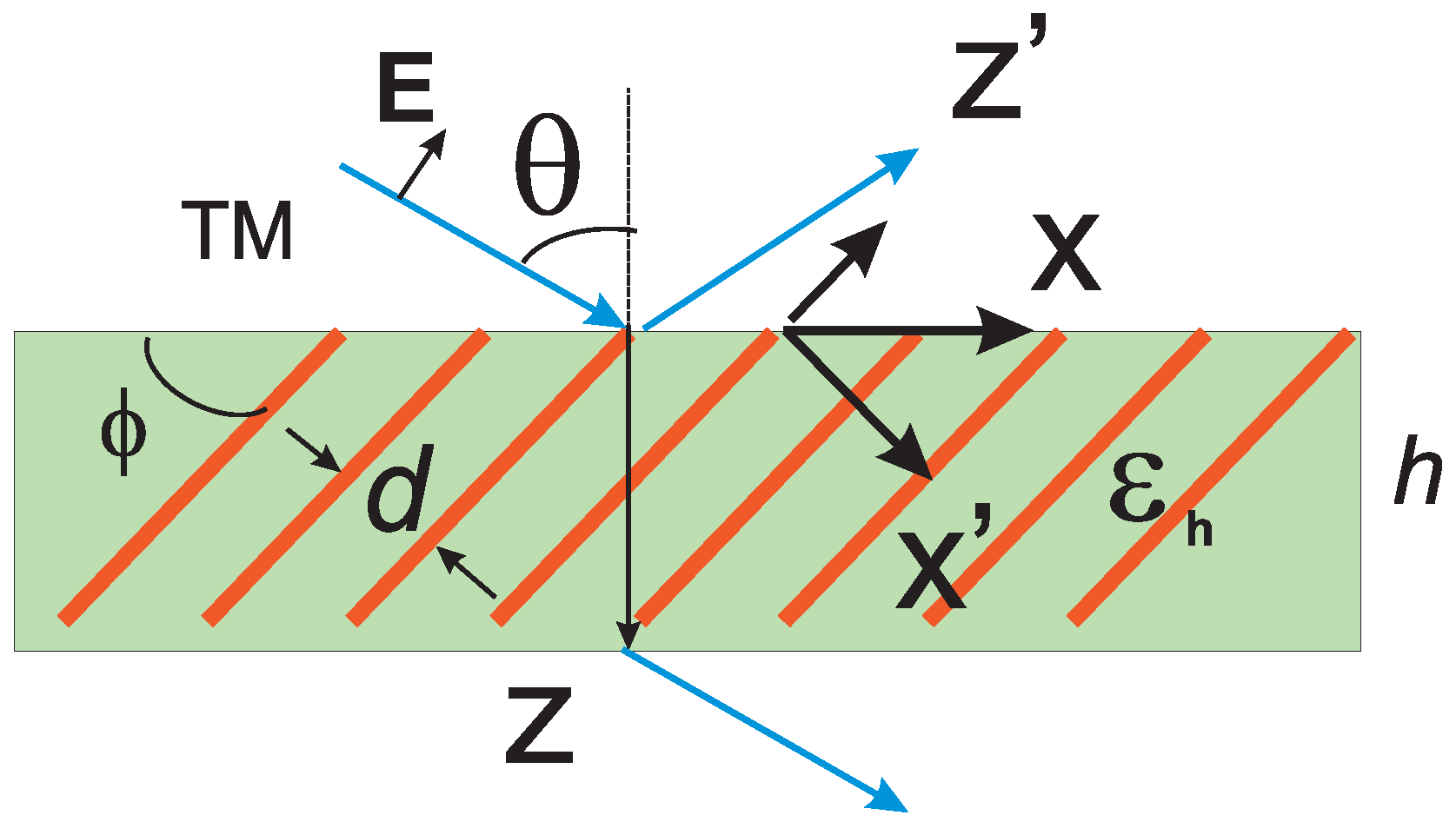
12]. Asymmetric hyperbolic metamaterial is a hyperbolic metamaterial with an optical axis, tilted with respect to a medium interface. Its schematic view is shown in
Figure 1, where the employed Cartesian coordinate systems
and
are defined. Asymmetry appears as a difference in properties of waves, propagating upward and downward with respect to the metamaterial interface under a fixed transverse wave vector component. The most important feature of AHMM is a possibility to excite a very slow wave in AHMM by a plane wave, incoming from free space, while a minimal reflection may be achieved [
13]. By other words, high density of states photons, excited in AHMM, can be perfectly coupled with photons in free space. Particularly, for graphene-based AHMM, this results in a broad-band total absorption of radiation in optically ultrathin layers of AHMM [
14] or in a strong gain in a thin layer of active graphene-based AHMM, as will be demonstrated in this paper. Finally, we note that our consideration relates to the TM-polarized waves, so the p-polarized component of radiation only is amplified.
Figure 1.
A sketch of amplifying graphene-based asymmetric hyperbolic metamaterial. Graphene sheets are orthogonal to the -plane and periodically arranged in the -direction. h denotes the thickness of graphene multilayer.
Figure 1.
A sketch of amplifying graphene-based asymmetric hyperbolic metamaterial. Graphene sheets are orthogonal to the -plane and periodically arranged in the -direction. h denotes the thickness of graphene multilayer.
2. Dynamic Conductivity of Graphene with Inversed Population of Carriers and the Effective Permittivity of the Graphene-Based AHMM
The model of the surface conductivity of graphene under pumping by optical illumination or by injection of electrons and holes was suggested in [
4]. Electron and hole densities in graphene can substantially exceed their equilibrium values and the electron and hole systems can be characterized by the quasi-Fermi energies
, respectively, and the effective temperature
T. The response of pumped graphene can be described by its complex-valued surface conductivity in the local approximation [
4]
Here
ω is the frequency of the incident THz wave,
e is the electron charge,
ℏ is the reduced Planck constant,
is the Boltzmann constant,
T is the temperature,
τ is the phenomenological electron and hole scattering time, and
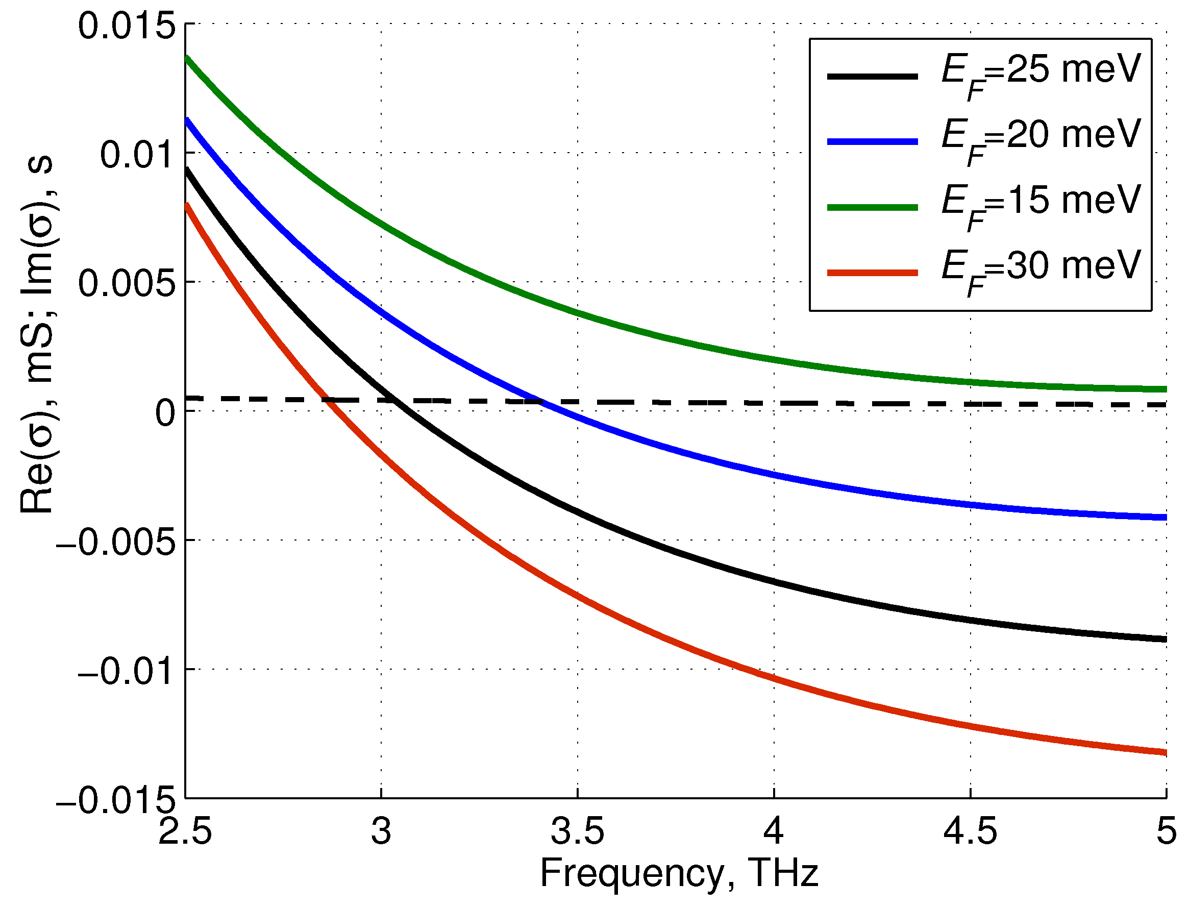
Figure 2.
Real part of the dynamic conductivity, calculated for different Imaginary part of σ calculated at = 25 meV, is shown by the dashed curve.
Figure 2.
Real part of the dynamic conductivity, calculated for different Imaginary part of σ calculated at = 25 meV, is shown by the dashed curve.
Figure 2 shows that the real part of the dynamic graphene conductivity changes sign at terahertz frequencies and graphene becomes an active material. At the same time, the imaginary part of the conductivity is positive, (
mS),
i.e., graphene can be considered as an inductive impedance surface.
Let us consider a graphene multilayer, formed of periodically arranged graphene sheets with period
d, embedded into a host matrix. Dispersive properties of such a graphene metamaterial have been studied in [
9], where the periodicity was taken into account. Here, we use the effective medium model which was verified comparing with the more accurate model (see [
14]). The effective relative permittivity tensor of the graphene multilayer (Maxwell-Garnett homogenization) has form:
Two diagonal components of the relative permittivity tensor in the coordinate system
read as
,
where
is the permittivity of a host matrix,
is the permittivity of vacuum.
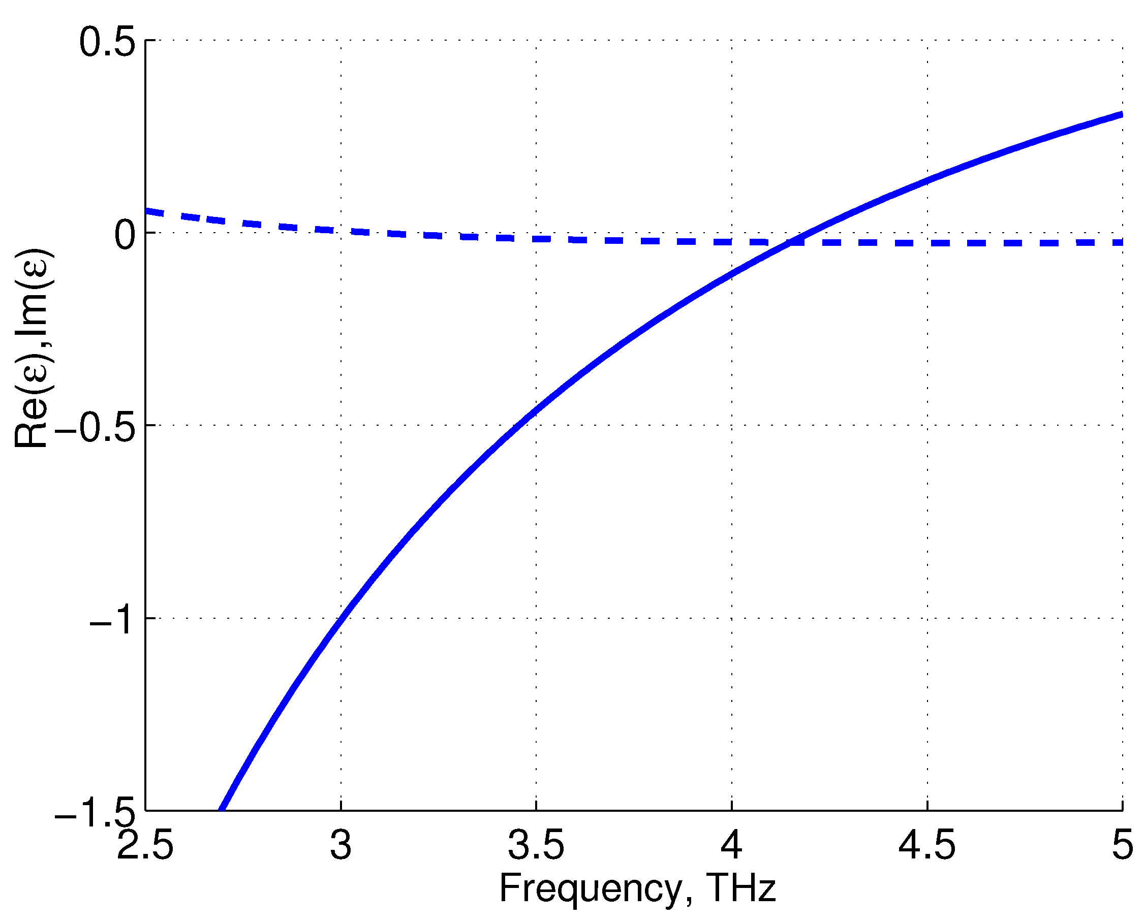
Figure 3 illustrates the frequency dependence of
for the graphene-based AHMM, described in terms of the effective medium theory. One can see that
changes sign at the frequency
THz. At the same time,
is the negative up to
THz.
The host matrix also may be inhomogeneous with period consisting of two or more layers (substrates for graphene sheets). In this case the structure can be considered as a photonic hypercrystal [
15] and we can speak about an effective permittivity of the host matrix. Thus, choosing period
d and the effective anisotropic permittivity
we can engineer an active HMM for a required frequency range.
Figure 3.
of the graphene multilayer, calculated at , m, meV, s, K. Solid and dashed curves correspond to the real and imaginary parts of , respectively.
Figure 3.
of the graphene multilayer, calculated at , m, meV, s, K. Solid and dashed curves correspond to the real and imaginary parts of , respectively.
3. Eigenwaves and Energy Flows in AHMM
To solve the problem of electromagnetic wave transmission through a slab of AHMM we have to find normal wave vector components in coordinate system , associated with slab interfaces. First we transform the permittivity tensor components to the system , where it takes a non-diagonal form.
As stated above, the permittivity tensor of the graphene metamaterial has the Equation (
3) in the primed coordinate system
. The Cartesian components of
in the coordinate system
read:
Thus, the permittivity tensor becomes non-diagonal, but symmetric,
i.e.,
. Substituting the tensor components Equation (
5) into Maxwell equations, we obtain the normal component of the wave vector in AHMM [
13]:
where
and
, is determined by the incidence angle
θ. Here
,
, correspond to signs “+” and “−”, respectively.
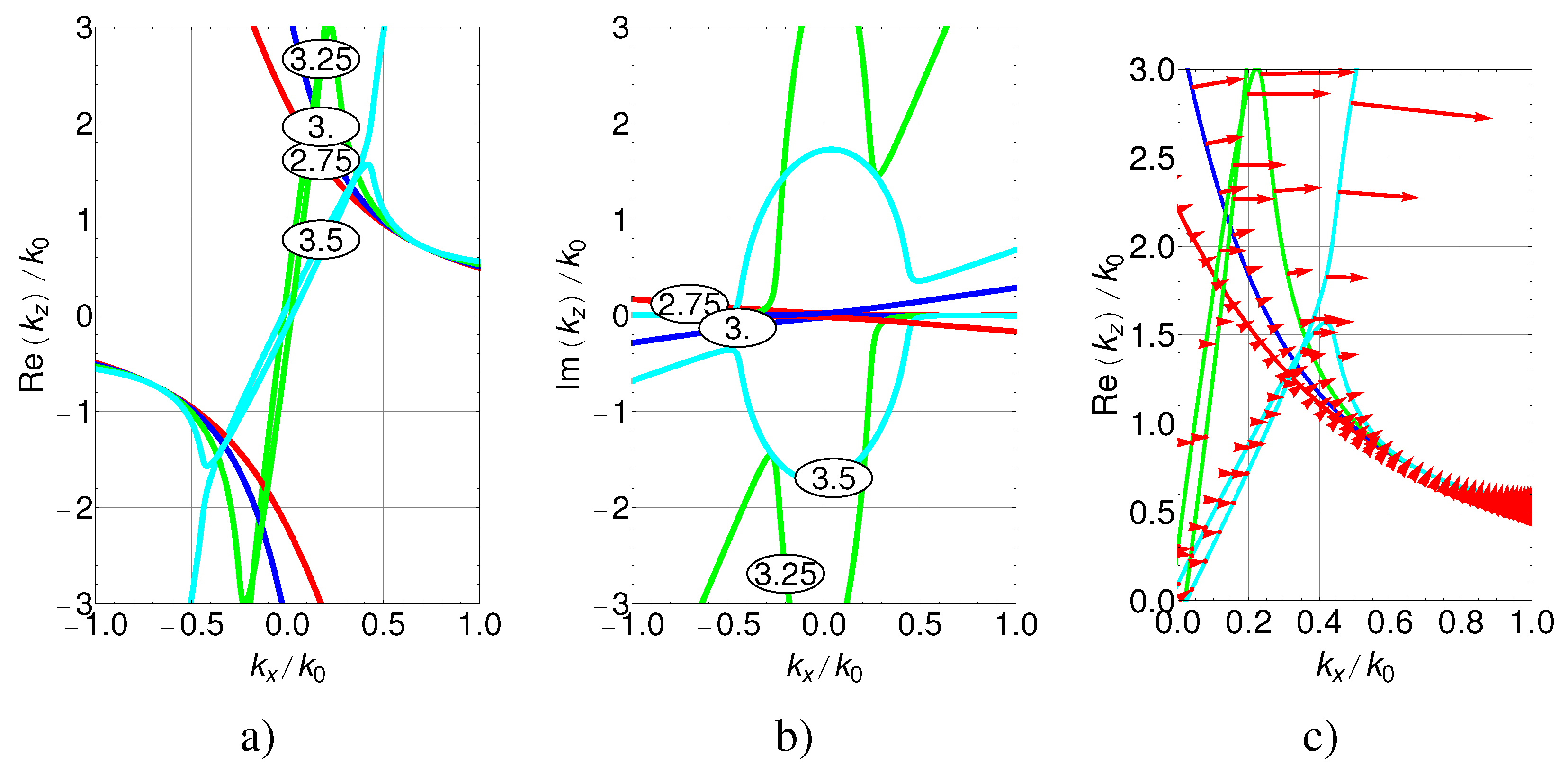
Figure 4.
Isofrequencies of the graphene multilayer medium (real part of
(
a), imaginary part of
(
b)), calculated for frequencies 2.75 (red), 3 (blue), 3.25 (green), and 3.5 (cyan) THz and energy flow directions (c), calculated for the same set of parameters as in
Figure 3 and
.
Figure 4.
Isofrequencies of the graphene multilayer medium (real part of
(
a), imaginary part of
(
b)), calculated for frequencies 2.75 (red), 3 (blue), 3.25 (green), and 3.5 (cyan) THz and energy flow directions (c), calculated for the same set of parameters as in
Figure 3 and
.
In
Figure 4 the isofrequencies
THz are shown
. Since
is complex for gain or loss medium, providing the frequency
ω is real, the isofrequencies at the planes
and
are shown separately, demonstrating hyperbolic dispersion (
Figure 4a), gain for the frequencies 3.0, 3.25, and 3.5 THz and losses for 2.75 THz (
Figure 4b). The directions of energy flow were calculated using the components of Pointing vector:
, where the medium eigenwaves vectors are
,
. In
Figure 4c the red arrows, presenting the
, are plotted along the corresponding isofrequency curves demonstrating the directions of energy flow. Due to different scales along
and
axes the directions of
were changed
to show visually the orthogonality of the directions of energy flow to the isofrequencies in the regions of waves propagating with low losses/gain. These results are useful for choosing the proper branches of the solutions for
, and demonstrate that the energy flows go mostly along the
x-axis of the multilayer.
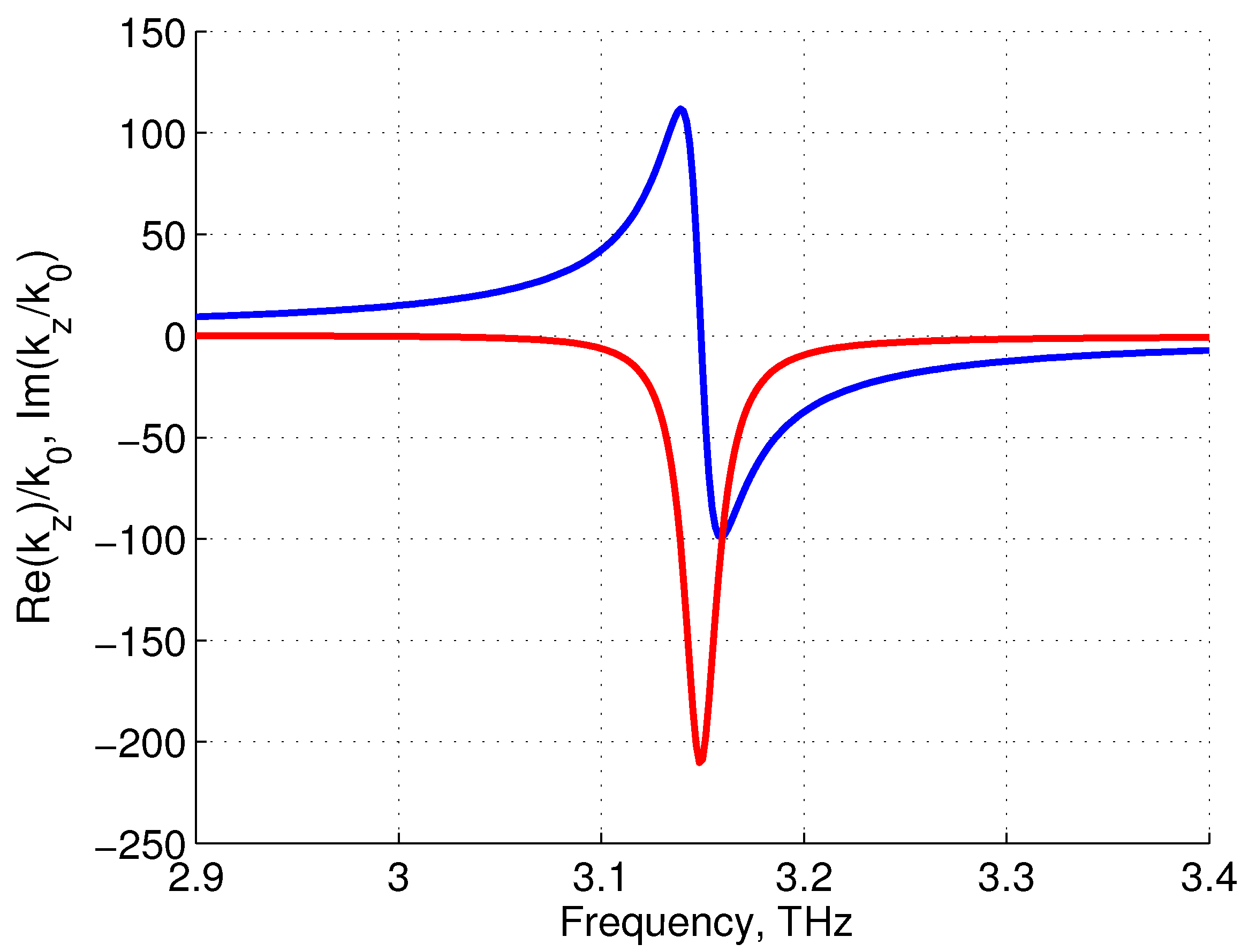
Figure 5.
Real (blue) and imaginary (red) parts of , calculated at meV, , , , m, s, K.
Figure 5.
Real (blue) and imaginary (red) parts of , calculated at meV, , , , m, s, K.
Figure 5 demonstrates the Lorentz resonance-like dependence of
. It shows that in vicinity of the frequency
THz the real part of
changes sign and becomes very large. At the same time,
is very large and negative that demonstrates a gain in AHMM. The value of
is small, approximately the same as in host medium, since it corresponds to the wave whose electric field vector is orthogonal to graphene sheets and does not interact with the graphene plasmonic system. Note that this resonance is not a size resonance since the size does not enter Equation (
6) and the resonant frequency depends only on such a geometrical parameter as the tilt angle
ϕ. We will show below that despite
and
are very large, the perfect matching with free space can be achieved [
13,
14] and the most efficient interaction between an incoming radiation and plasmonic system can be provided.
4. Amplification of Terahertz Radiation
Next, we will consider a plane wave propagation through a finite-thickness slab of the graphene-based AHMM using the
transfer matrix method, modified for the general case
. This transfer matrix reads [
13]:
where
and
are transverse wave impedances for AHMM, corresponding to upward and downward waves, which are expressed as [
13]:
where
Ω. For low-loss HMM with Im(
)=0,
,
, the Brewster angle
, which corresponds to zero reflection, is expressed as [
16]
where
.
The transmission coefficient
t can be calculated using the formula:
where
. The reflection coefficient reads as
Absorption
A is defined as
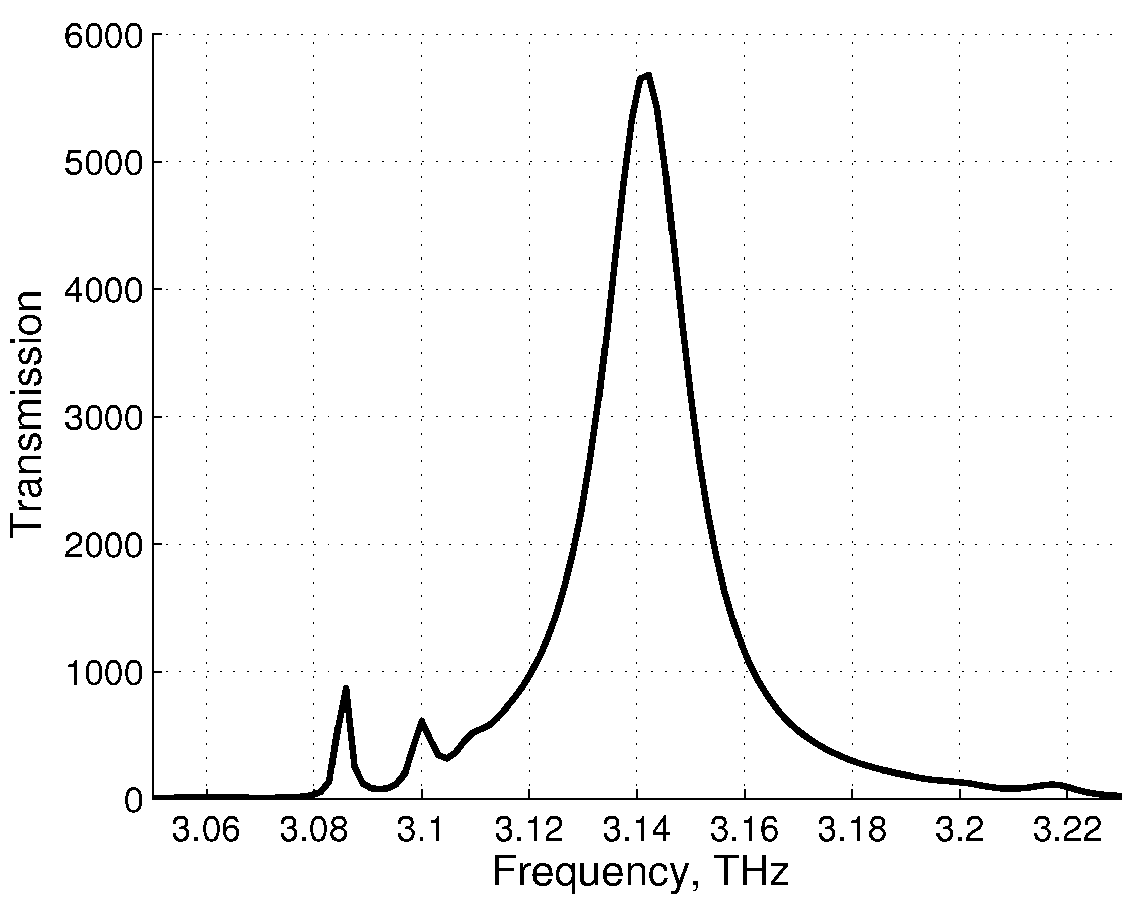
Figure 6.
Amplified transmission, calculated at the same asymmetric hyperbolic metamaterials (AHMM) parameters as above. The thickness of the graphene-based AHMM slab m.
Figure 6.
Amplified transmission, calculated at the same asymmetric hyperbolic metamaterials (AHMM) parameters as above. The thickness of the graphene-based AHMM slab m.
Figure 6 illustrates transmission of the plane THz wave trough the graphene-based amplifying structure. Note, that the reflection is practically absent. Here we observe a wider amplification band, 0.6% instead 0.03%, estimated from [
5] at the same
s. The peak of transmission corresponds to the plasmon lasing regime which correct consideration demands nonlinear theory of graphene conductivity in the field of THz radiation. We expect, that the limitations of our model is similar to claimed in [
5], that is about
.
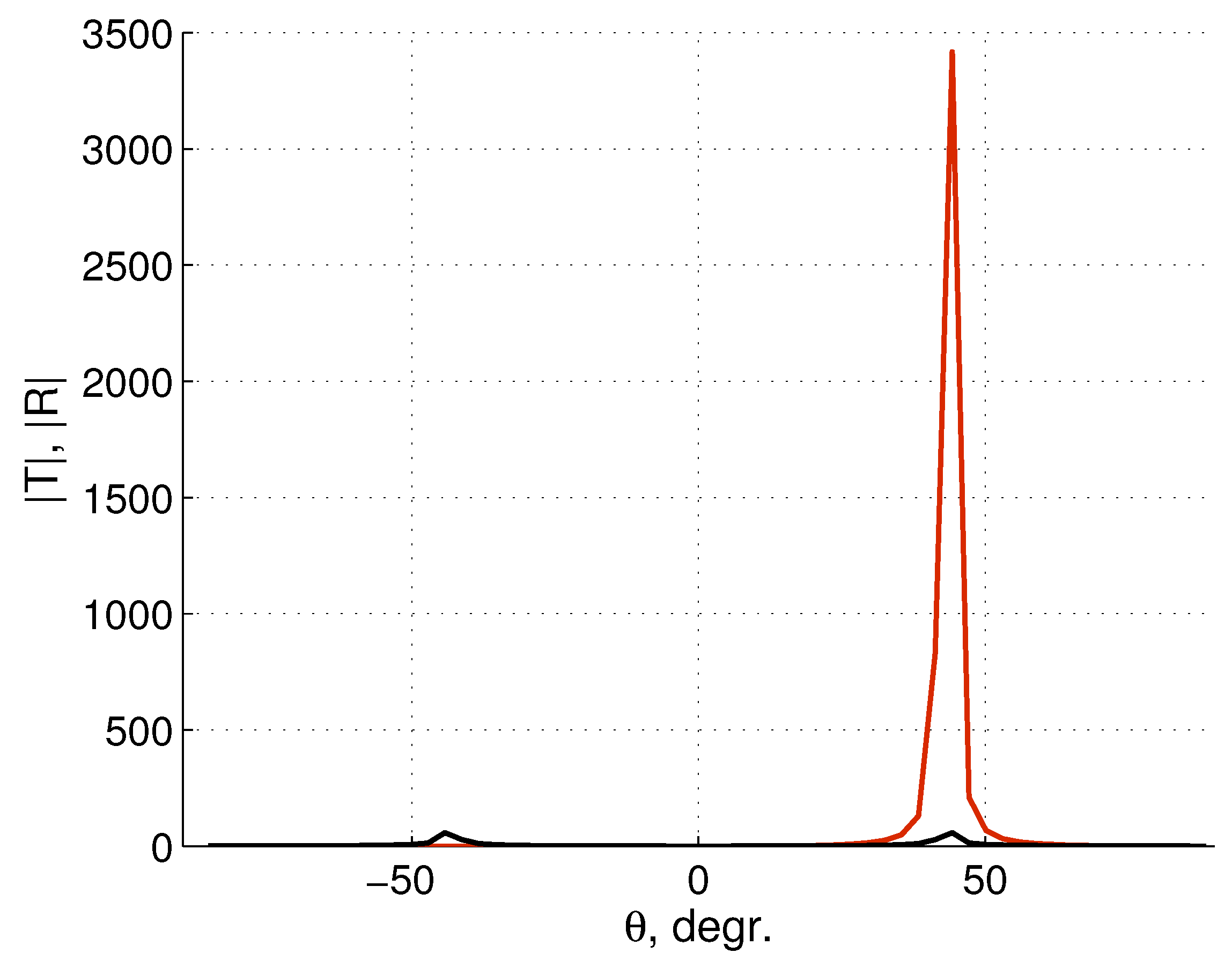
Figure 7.
Transmission (red) and reflection (black) coefficients.
Figure 7.
Transmission (red) and reflection (black) coefficients.
The angle dependence of amplification, calculated at 3.14 THz, and the same as above other parameters, is shown in
Figure 7. Here we observe amplification not only for the transmitted wave, but also for the reflected one. However, the peak of amplified reflected wave is about of 60 that
times less than the height of the transmission peak.
Figure 7 demonstrates a high sensitivity of amplification to the incidence angle
θ. The angle asymmetry appears only for the transmission.
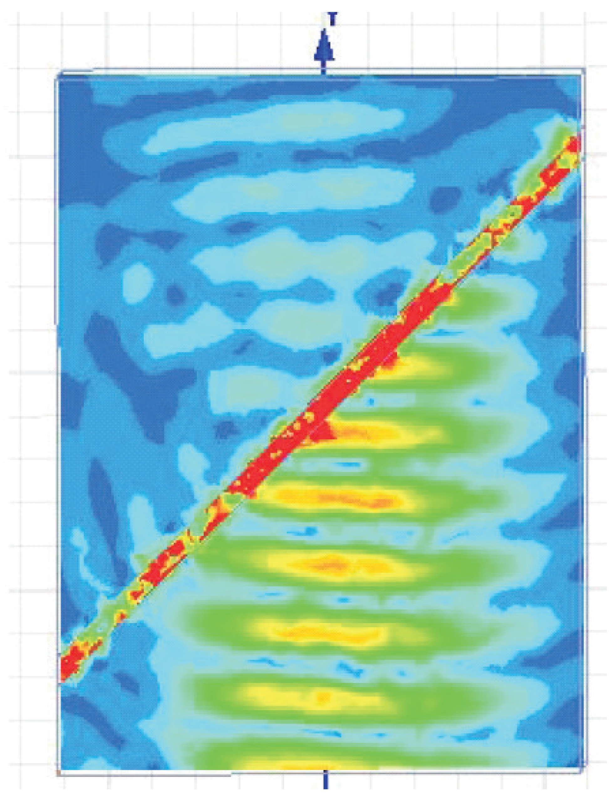
Figure 8.
Amplification of the Gaussian beam, shown in the plane.
Figure 8.
Amplification of the Gaussian beam, shown in the plane.
Figure 8 shows result of ANSOFT HFSS numerical simulation for a Gaussian beam, incident onto graphene-based amplifying AHMM. The optical axis is parallel to the
-axis, as in
Figure 1. Narrow Gaussian beam and absorbing boundary conditions were used due to the absence of the
symmetry plane for this structure. Simulations were implemented at the frequency
THz. The slab thickness equals to
, where
λ is the wavelength of the incident light.
5. Conclusions
In conclusions, we have suggested a structure, potentially realizing extremely strong coupling between photons in free space and high density of states THz plasmons, excited in graphene-based AHMM. A giant amplification of terahertz radiation in this structure can be achieved due to the stimulated generation of plasmons in graphene sheets. Unlike amplification of surface plasmons in an array of graphene resonant nanocavities [
5], plasmons in AHMM can be considered as “volume plasmons” in the metamaterial. Due to the absence of such resonant elements as micro/nanocavities, we obtain a significantly wider-band amplification. Existence of the lasing regime also is observed, however, its investigation cannot be implemented in framework of a linear model. Despite of technological difficulties associated with the manufacture of asymmetric graphene-based HMM, we consider our approach as a promising for creation of plasmonic graphene amplifiers and generators for the THz frequency range. Asymmetric HMMs can be fabricated from any plasmonic materials, such as metallic carbon nanotubes [
13], noble metals [
12,
17] and doped silicon [
12],
etc. Since in this work the considered metamaterial is the periodic structure with a very small period, much smaller than a THz wavelength and considerably smaller, than the wavelength in AHMM, we could exploit the local effective medium model. More accurate nonlocal models, like [
18], which take into account a spatial dispersion, may be used if needed.
