Review

Optical Scattering Cancellation through Arrays of Plasmonic Nanoparticles: A Review

1
Niccolò Cusano University, Via Don Carlo Gnocchi 3, Rome 00166, Italy
2
Department of Electrical and Computer Engineering, The University of Texas at Austin, Austin, TX 78712, USA
3
Department of Engineering, "Roma Tre" University, Via Vito Volterra 62, Rome 00154, Italy
*
Author to whom correspondence should be addressed.
Photonics 2015, 2(2), 540-552; https://doi.org/10.3390/photonics2020540
Submission received: 14 April 2015 / Revised: 12 May 2015 / Accepted: 12 May 2015 / Published: 18 May 2015
(This article belongs to the Special Issue New Frontiers in Plasmonics and Metamaterials)

Abstract

:
In this contribution, we review and discuss our recent results on the design of optical scattering cancellation devices based on an array of plasmonic nanoparticles. Starting from two different analytical models available to describe its electromagnetic behavior, we show that a properly designed array of plasmonic nanoparticles behaves both as an epsilon-near-zero metamaterial and as a reactive metasurface and, therefore, can be successfully used to reduce the optical scattering of a subwavelength object. Three different typologies of nanoparticle arrays are analyzed: spherical, core-shell, and ellipsoidal nanoparticles. We prove, both theoretically and through full-wave simulations, that such nanostructures can be successfully used as a cloaking device at ultraviolet and optical frequencies.

1. Introduction

Electromagnetic cloaking is undoubtedly one of the most interesting and appealing applications of metamaterials and metasurfaces. With the term cloaking we usually refer to the techniques able to reduce the overall scattering and absorption of an object within a desired range of frequencies. Over the last ten years, several techniques, based on different physical principles, have been proposed [1,2,3,4,5,6,7]. Among these techniques, the one known as scattering cancellation is particularly interesting because its operation does not rely on the isolation of the hidden object from the external electromagnetic field. This peculiar property allows the design of conceptually new devices that are having a dramatic impact in both sensor and antenna systems [8,9,10,11,12,13].
The working principle of a scattering cancellation device is very intuitive. Basically, the object to hide is covered by a conformal cloak designed in such way that, when illuminated by an external wave, it scatters a field having the same amplitude but opposite phase with respect to the one due to the object. The destructive interference between the two scattered fields is responsible for a dramatic reduction of the object visibility.
The scattering cancellation effect described above can be achieved using two different kinds of covers, a volumetric cloak exhibiting a negative or near-zero value of its electric permittivity [5] or an ultrathin surface patterned on a subwavelength scale [6]. In the last few years, these two techniques, named plasmonic and mantle cloaking, respectively, have been thoroughly developed at microwave frequencies, due to the possibility to design both epsilon-near-zero (ENZ) metamaterials and purely reactive metasurfaces. In particular, mantle cloaking is characterized by a straightforward design and an easy realization, relying on cheap and light microwave metasurfaces exhibiting a desired value of their intrinsic surface reactance [14,15,16].
In contrast, the design of a scattering cancellation device at optical frequencies is not an easy task. Due to the absence of natural materials whose plasma frequency lies in the visible range, the implementation of the required ENZ materials has been first proposed by using alternating layers of plasmonic and non-plasmonic materials [17]. Though this solution represents the first attempt to implement scattering cancellation cloaks working in the visible, it is far from being ready for a possible practical implementation, due to the use of few-atom thick layers of noble metals. As an alternative route to solve the issue, our, and other, groups have explored the use of a mixture of plasmonic nanoparticles (NPs), leading to working cloaks in UV [18,19,20].
Starting from the mentioned results, we have further explored other possible designs in order to bring the operation frequency of the cloak down to the visible spectrum. The first design is based on proper arrangements of core-shell NPs, resulted in a lower operative frequency of the cloak down to the blue region of the visible [21,22]. More recently [23], instead, we have exploited an innovative metasurface model to design engineered NP arrays capable to meet the mantle cloaking requirements within the whole visible range.
In this paper, we review our latest findings on the characterization and design of NP-based scattering cancellation devices working at optical frequencies. In particular, in Section 2, we present an accurate theoretical model of a NP array using two different theories: a volumetric one, based on the Maxwell-Garnett homogenization of the electric permittivity, and a bi-dimensional one based on the average surface reactance concept. In Section 3, we present the results of the full-wave simulations of the NP arrays used as optical cloaking devices. The numerical results are in excellent agreement with the theoretical ones, confirming the accuracy of the proposed analytical models.

2. Analytical Models

In this section, we describe two different analytical models to describe the electromagnetic behavior of a NP array. The first one is an approximate technique based on the effective medium approach [24], whereas the second one is based on a 2D analytical model that recently appeared in the literature [25,26].

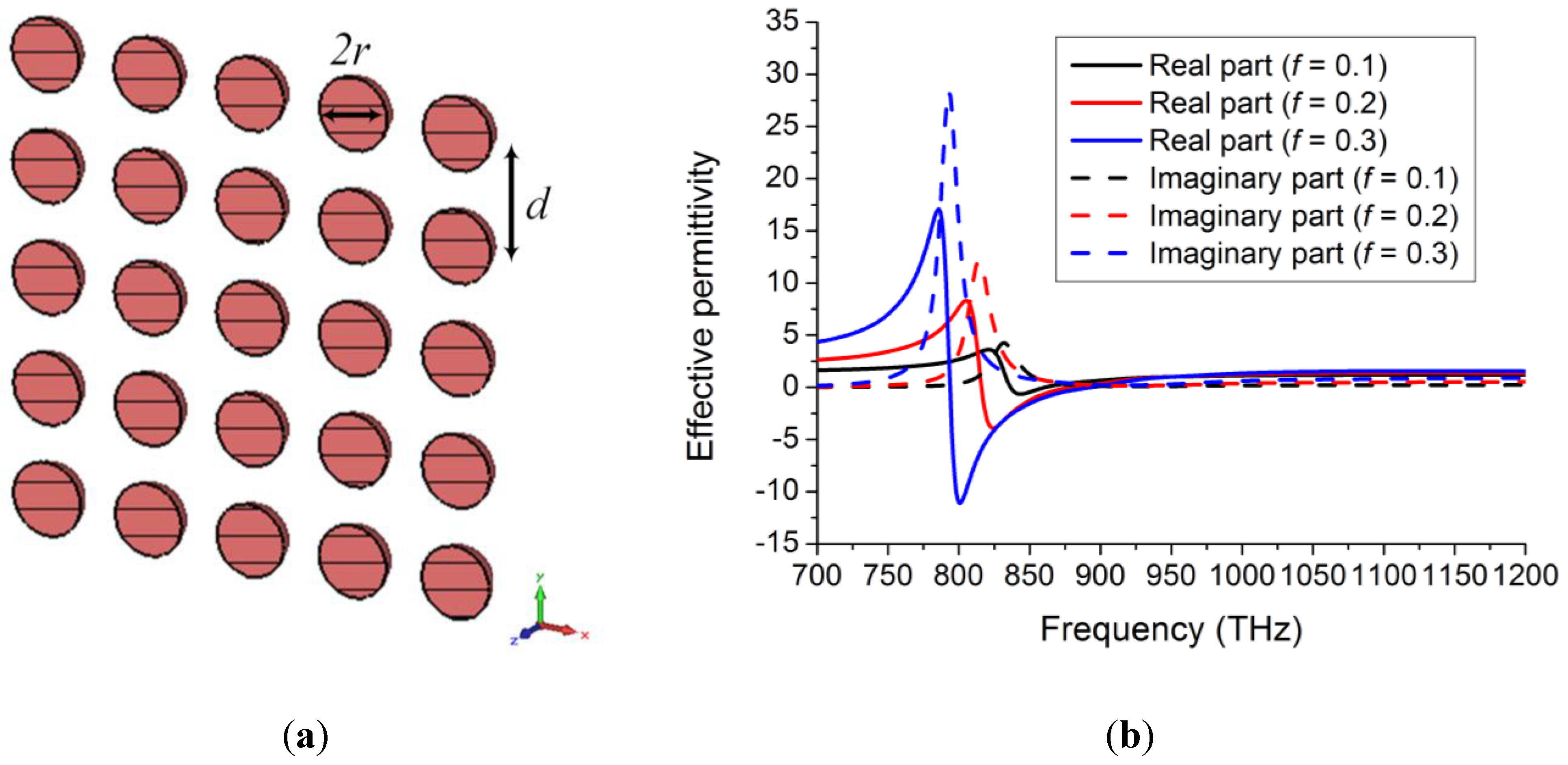
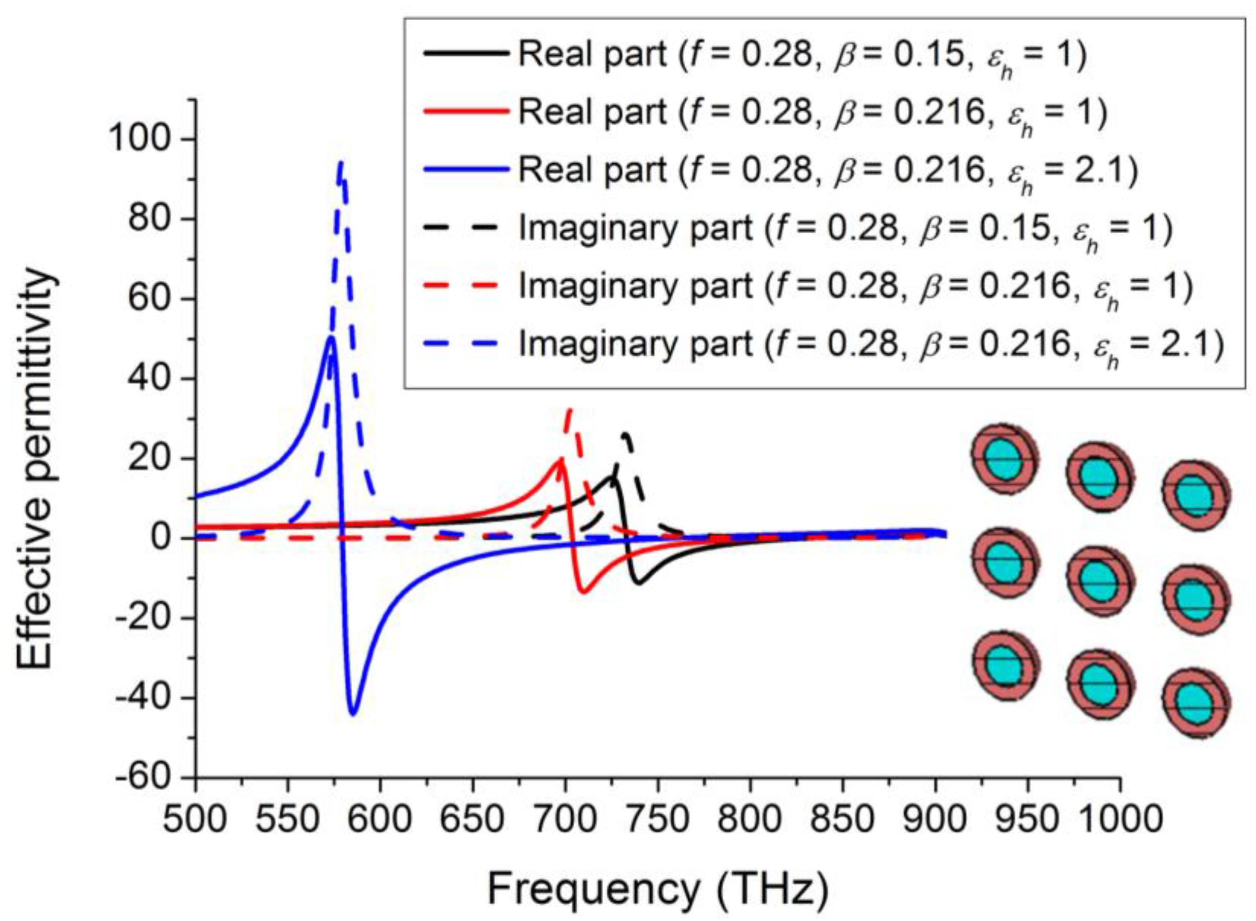
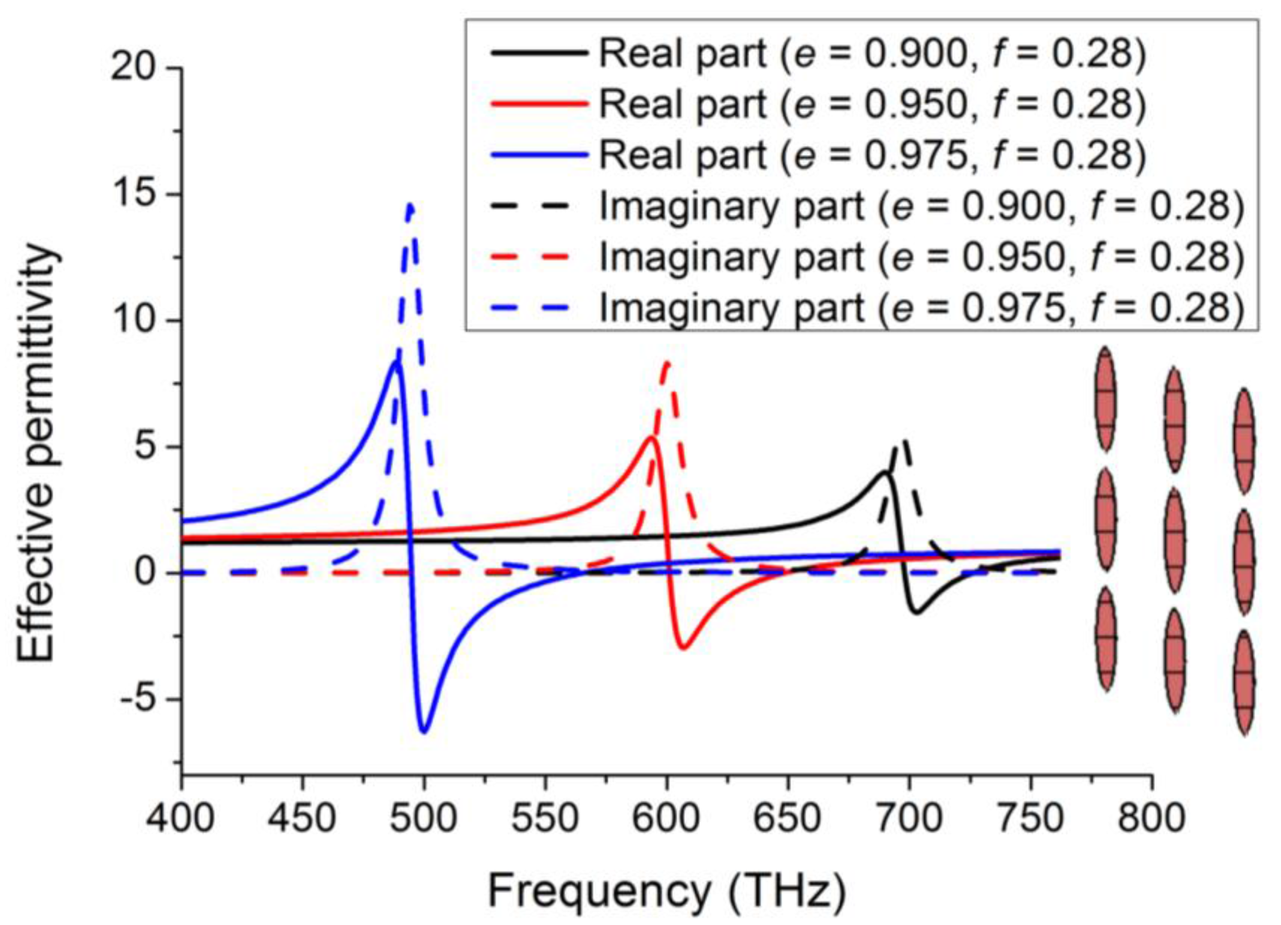
2.1. Volumetric Homogenization

Let us consider the square array shown in Figure 1a, composed by electrically small NPs separated by a distance d and embedded in a dielectric matrix with a lossless permittivity εh. According to the Maxwell-Garnett homogenization [24], for a non-dense array [27], the homogenized permittivity εeff is given by:
ε e f f = ε h + n α 1 n α / ( 3 ε h )
being n the density of the dipole moments in the mixture and α the polarizability of a single NP whose expression is strongly dependent on the NP shape. It is worth remarking that, even though a metal-dielectric mixture composed by a single layer of metallic particles cannot rigorously be treated as a 3D composite, a good agreement between the homogenized Equation (1) and the full-wave simulations has been obtained [18,19,20,21,22]. This means that the 3D volumetric model represents, indeed, a good starting point for the cloak design, which can be further refined with a numerical optimization.
Figure 1. (a) Array of spherical plasmonic NPs. (b) Effective relative permittivity of different arrays of spherical silver NPs embedded in air.
Photonics 02 00540 g001
We first consider the case of spherical bulk NPs, whose polarizability is equal to [24]:
α s p h e r e = 3 ε 0 V ε N P 1 ε N P + 2
being εNP the permittivity of the material composing the NPs and V the volume of the sphere. By replacing Equation (2) in Equation (1) we get a closed-form expression of the effective permittivity of the NP mixture where f = nV is the mixture filling factor.
According to the plasmonic cloaking approach [5], in order to achieve an optical scattering cancellation effect we need to design a cover whose effective relative permittivity is close to zero within the visible range. It is easy to understand that, for this purpose, the choice of the plasmonic materials composing the NPs is of paramount relevance. Natural materials exhibiting the closest plasma frequency to the visible spectrum are the noble metals, such as gold and silver [28,29]. However, due to the inter-band transitions and the related significant losses in the violet/near-UV region that characterize the electric behavior of gold, silver is generally considered as the best choice for the design of a scattering cancellation device.
After the choice of the plasmonic material composing the NPs, it is possible to estimate the array effective permittivity. In Figure 1b, we report the values returned by Equation (1) as a function of frequency for different values of the array filling factor f. Here, the bulk data [29] have been used to characterize silver. As can be appreciated, in all the cases the mixture exhibits a significantly lower plasma frequency compared to the bulk silver (i.e., ωp = 9.17 eV). This is the reason why a similar design has been successfully used in [18,19] to design and realize a plasmonic cover working in the near UV around 900 THz. Please note that the ENZ region exhibited by the effective medium is quite far from the resonance. This is a non-trivial observation, since the model validity around the resonance is doubtful [27] and, moreover, this also ensures a minimum of the imaginary part of the mixture effective permittivity.
The results shown above, however, prove that a mixture of spherical NPs is not able to return an ENZ behavior within the optical spectrum. Therefore, it is important to investigate the behavior of different configurations of NPs to further lower the effective plasma frequency of the NP array. In particular, in [21] and [23], we have explored the electromagnetic behavior of core-shell and ellipsoidal NPs, respectively. As shown in the inset of Figure 2, a core-shell NP consists of a dielectric core, with radius r2 and permittivity ε2, and a plasmonic shell with radius r1 and permittivity ε1. Once δ = r 2 3 / r 1 3 is defined, the polarizability of a core-shell NP can be expressed as [21]:
α s p h e r e c o r e s h e l l = 3 ε h V ( ε 1 ε h ) ( ε 2 + 2 ε 1 ) + β ( 2 ε 1 + ε h ) ( ε 2 ε 1 ) ( ε 1 + 2 ε h ) ( ε 2 + 2 ε 1 ) + 2 β ( ε 1 ε h ) ( ε 2 ε 1 )
If we consider an anisotropic geometry, as the ellipsoidal one shown in the inset of Figure 3, the NP polarizability becomes a tensorial quantity. In order to cloak an electrically small object, we are mainly interested in the polarizability along the major axis of the ellipsoid, whose expression is equal to [30]:
α e l l i p s o i d y = V 4 π ε N P y ε h ε h + L ( ε N P y ε h )
being L the depolarization factor depending on the NP eccentricity. Equations (3) and (4) in combination with Equation (1) allow calculating the effective permittivity of both an array of core-shell and ellipsoidal NPs.
The effective permittivities of these two array configurations are shown in Figure 2 and Figure 3, respectively. As can be appreciated, the core-shell structure is able to lower the effective plasma frequency of the array compared to the bulk spherical NP arrays. Moreover, if the NPs array is embedded in a silica matrix, the ENZ frequency range reaches the violet region of the optical spectrum, as in [21]. The ellipsoidal NPs, instead, allow achieving a plasma frequency ranging within the whole visible range and, therefore, can be considered as one of the first realistic implementations of an ENZ artificial material working at optical frequencies [23]. Please note that, in all the cases reported in Figure 1, Figure 2 and Figure 3, the imaginary part of the effective permittivity exhibits a minimum within the near-zero region, ensuring the proper operation of these structures when used as cloaking devices.
Figure 2. Effective relative permittivity of different arrays of core-shell NPs composed by a silver shell and a silica core embedded in a dielectric matrix with permittivity εh. Please note that the last example refers to an array of core-shell NPs in a silica matrix (εh = 2.137).
Photonics 02 00540 g002
Figure 3. Effective relative permittivity of an array of silver ellipsoidal NPs for different values of the NP eccentricity e.
Photonics 02 00540 g003

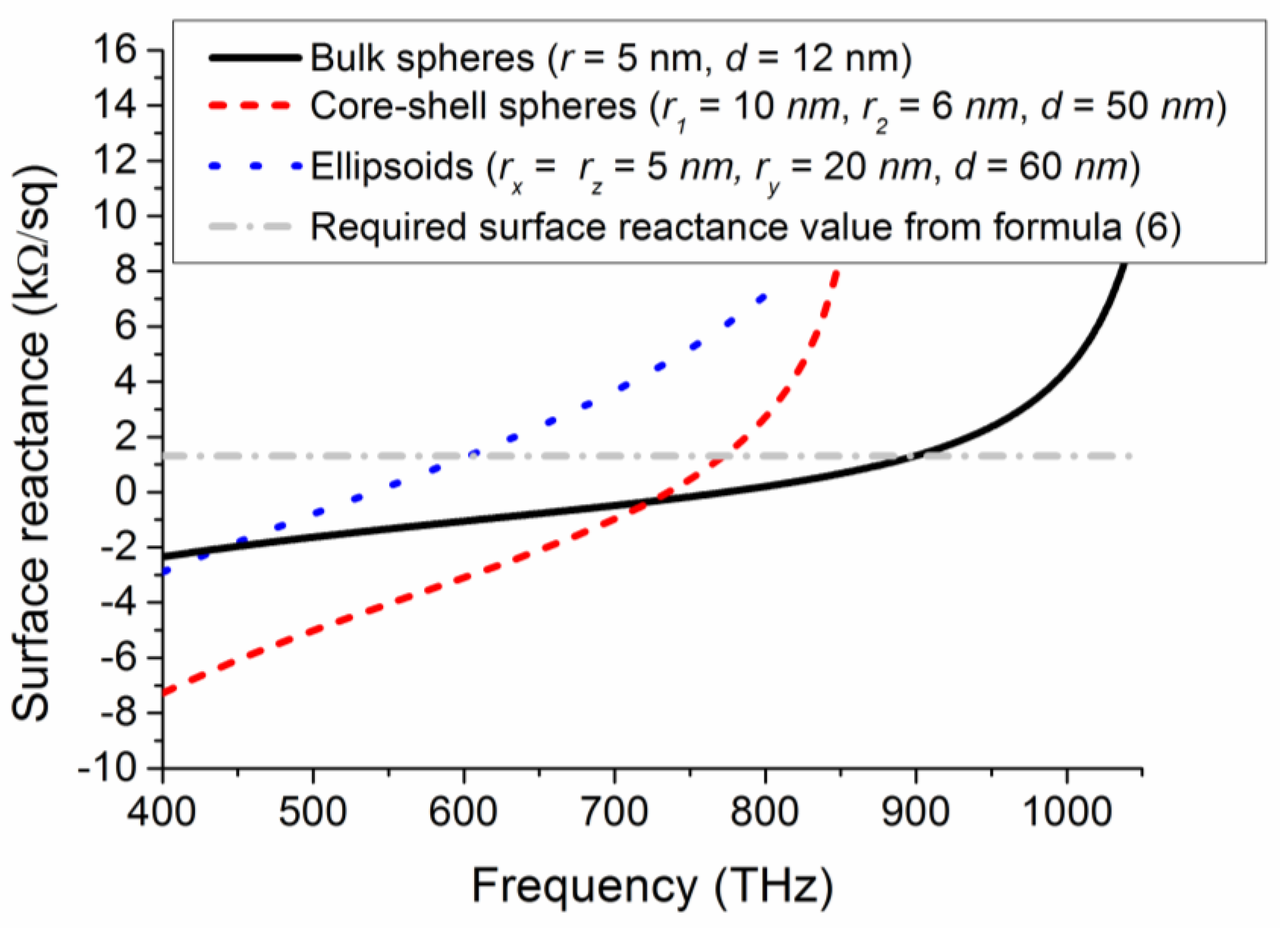
2.2. Metasurface Homogenization

We consider again the square array shown in Figure 1. Due to the electrically small size and separation distance among the NPs, it is possible to characterize the array through a bi-dimensional model describing the electromagnetic behavior of the array in terms of an average surface reactance [25,26]. This model has proven to be more accurate than the volumetric one described in the previous Subsection that does not rigorously meet the conditions of the volumetric homogenization [23].
According to the metasurface model developed in [25], the average surface reactance Xs exhibited by an array of NPs is equal to:
X s = d 2 k ( Re { α 1 } Re { β } )
being β the interaction constant among the NPs and k the wavenumber of the host medium. Using the approximate closed-form expression of β for a normally incident plane-wave [31] and the NP polarizabilities (2–4) it is possible to compute the average surface reactance exhibited by the array of spherical, core-shell, and ellipsoidal NPs, respectively. Please note that, for analytical reasons, we use here a lossless Drude model to Equation (5), as in [23]. This choice does not affect the validity of the achieved results since a rigorous lossy model will be anyway used in the full-wave simulations described in the next section.
Figure 4. Average surface reactance exhibited by an array of spherical NPs (continuous line), core-shell NPs (dashed line), and ellipsoidal NPs (dash-dotted line).
Photonics 02 00540 g004
In Figure 4, we show the average surface reactance analytical values Equation (5) exhibited by the three different typologies of NP arrays described above within the visible spectrum. These values are compared to the ideal surface reactance values required by the mantle cloaking approach for a dielectric cylinder [6], for example:
X s i d e a l = 2 ω a γ ε 0 ( ε r 1 )
being εr the relative permittivity of the cylinder and γ the ratio between the radius of the cylinder a and the one of the cover ac. Due to the small value of the relative permittivity of dielectrics at optical frequencies, the required cloak needs exhibiting a strong inductive reactance, as shown in Figure 4 (dot-dashed line), where we have fixed γ = 0.83 and a = λ0/10. As can be appreciated in the same plot, the three different NP arrays described in the previous Subsection are able to meet the mantle cloaking requirements in different frequency ranges. In particular, spherical bulk, core-shell, and ellipsoidal NPs are strongly inductive in the near-UV, higher optical, and optical region, respectively. These results confirm the ones of the previous Subsection, obtained through a different homogenization model, and the ones recently appeared in literature [18,19,20,21,22,23].

3. Full-Wave Simulations

In the previous section, we have proven that an optical scattering cancellation effect can be achieved using an array of both core-shell and ellipsoidal NPs. However, while the core-shell array operation is limited to the higher optical spectrum, the ellipsoidal ones allow the design of covers operating within the entire optical range. Moreover, as it will be clear soon, the ellipsoidal NP array also exhibits significantly better cloaking performances compared to the core-shell ones.
In fact, before implementing the designed structures in a full-wave simulator, it is important to make some observations about the electromagnetic model used to describe the plasmonic materials composing the NPs. In the 3D homogenization model described in the previous Section, we have used the measured data taken from [29]. Since the characteristic dimensions of a NP are generally smaller than the silver free mean path, the measured bulk permittivity may underestimate the material losses that have an important influence on the cover cloaking performance. An accurate modeling of the electromagnetic behavior of silver, therefore, is highly required. For this purpose, we use here a size-corrected Lorentz-Drude dielectric function that takes into account the additional losses provided by the surface dispersion effects. Silver permittivity, thus, can be expressed as follows [32]:
ε N P ( ω , r ) = 1 ω p 2 ω [ ω j γ ( r ) ] + f ω L 2 ω L 2 ω 2 + j Γ L ω
with γ ( r ) = γ m + γ s ( r ) (the description of the other parameters can be found in [32]). The term γ is the damping constant of the material and consists of two terms, γm that is the term describing the dispersion of electrons by the ions and γs(r) takes into account the surface dispersion effects. For a spherical NP, it is easy to prove that [32,33,34]:
γ s ( r ) = A v F r
being vf the Fermi velocity of the plasmonic material, r the radius of the NP, and A a correction term needed to interpolate the experimental data [35].
It is now easy to understand why the ellipsoidal NPs are the best candidate to realize an optical cloak. Since the additional losses due to the surface dispersion effects are inversely proportional to the NP dimensions, as evident in Equation (8), to achieve high performances it is important to design a cloak composed by NPs with non-critical size. As an example, in Figure 5 we show the comparison between the bulk silver permittivity (taken from [29]) and the value returned by Equations (7) and (8) for a NP with radius r = 5 nm. A significant increase of losses can be observed. In particular, the imaginary part of the NP silver permittivity ranges from five times bigger (400 THz) to two times bigger (750 THz) than in the bulk case. As can be inferred from the legend of Figure 4, a very small shell of silver would be required to reach an inductive surface reactance in the optical spectrum (r2r1 = 4 nm). Conversely, the ellipsoidal NP arrays are composed by NPs elongated in the direction of the applied electric field and, therefore, the additional losses in the maximum scattering direction are kept very small with a consequent improvement in the overall cloaking performance.
Figure 5. Comparison between the silver bulk permittivity and the one obtained with the size-corrected model Equations (7) and (8) for NPs with radius r = 5 nm.
Photonics 02 00540 g005
To verify these theoretical observations, we have implemented Equation (7) into a 3D full-wave simulator. Since ellipsoidal NPs are considered, an anisotropic effective permittivity taking into account the different mean free paths of the silver electrons along the three coordinate axes have been used. By exploiting the metasurface model developed in the previous section, we have designed three different ellipsoidal NP cloaks able to return a scattering cancellation effect for an infinitely long silica cylinder with permittivity εr = 2.137 within the red, green, and violet regions, respectively. The geometrical dimensions of the three cloaks, shown in the insets of Figure 6, Figure 7 and Figure 8, are: (i) rx = ry = 4 nm, rz = 28 nm, d = 60 nm, Ncolumn = 14; (ii) rx = ry = 5 nm, rz = 24 nm, d = 55 nm, Ncolumn = 12; (iii) rx = ry = 6 nm, rz = 20 nm, d = 45 nm, Ncolumn = 8, respectively. The radius of each cylinder to hide is r = λ0/10, being λ0 the cloaking design wavelength. Please note that, as expected, the eccentricity of the NPs reduces as the cloaking frequency increases. As a limit case, if a scattering cancellation in the UV range were desired, spherical NPs with eccentricity e = 0 would be required.
The results of the full-wave simulations are shown in Figure 6, Figure 7 and Figure 8, respectively, for both the total scattering cross section (SCS) and the extinction cross section (ECS). Since the dominant scattering contribution of a subwavelength cylinder is the one due to the TM polarization [6], an external plane wave with the electric field parallel to the axis of the cylinder has been used to excite the structure. In excellent agreement with the theoretical modeling, the designed cloaks result in a dramatic SCS reduction, quantifiable in about 12 dB, around 450, 600, and 750 THz, respectively. Please note that the SCS reduction shown in the plot is the most significant indication of the object total scattering since it is formally defined as the integral of the radar cross section (RCS) of the object all around the object itself [36]. Moreover, it is interesting to note that the total ECS, defined as the sum of the scattering and the absorption cross sections, is not increased in none of the three cases. This means that the SCS reduction returned by the cloaks is able to compensate the unavoidable increase in the absorption due to losses affecting the plasmonic NPs. We remark that this effect is mainly due to the elongated shape of the NPs, which significantly limits the surface dispersion effect Equation (8) compared to the spherical or the core-shell NPs.
Figure 6. Scattering cross section (SCS) and extinction cross section (ECS) of the first coated cylinder compared to the one of uncloaked cylinder.
Photonics 02 00540 g006
Figure 7. Scattering cross section (SCS) and extinction cross section (ECS) of the second coated cylinder compared to the one of uncloaked cylinder.
Photonics 02 00540 g007
Finally, in Figure 9 and Figure 10, we report the 3D SCS of the silica cylinder and the magnitude of the y-component of electric field in a plane perpendicular to the axis of the cylinder both in the uncloaked and cloaked case at 600 THz. The second cloak described above has been used for this comparison. As can be appreciated, the scattering cancellation effect returned by the cloak allows a reduction of the object scattering all around the cloaked object and to almost perfectly restore the planar phase front of the electric field around the cylinder. Please note also the different shape of the 3D scattering pattern in the two cases of Figure 9, due to the fact that the zero-th scattering mode excited by the cylinder has been almost totally suppressed by the cloak [5].
Figure 8. Scattering cross section (SCS) and extinction cross section (ECS) of the third coated cylinder compared to the one of uncloaked cylinder.
Photonics 02 00540 g008
Figure 9. 3D scattering cross section (SCS) of the second cylinder both in the uncloaked (left) and cloaked case (right). Please note the different plot scale.
Photonics 02 00540 g009
Figure 10. Magnitude of the y-component of the electric field on a plane perpendicular to the axis of the cylinder and passing for its center both in the uncloaked (left) and cloaked case (right).
Photonics 02 00540 g010

4. Conclusions

In this paper, we have reviewed our latest results on the design of optical scattering cancellation devices. First, we have discussed and compared two different analytical models commonly used to characterize the electromagnetic behavior of the NP array. The first one is based on a Clausius-Mosotti effective medium approximation whereas the second one is a bi-dimensional model able to describe a NP array in terms of its intrinsic surface reactance. These models allowed us to theoretically demonstrate that the NP array are suitable for the realization of a scattering cancellation based cloak working at optical or UV frequencies. In particular, we have demonstrated that ellipsoidal NPs represent a good candidate to implement a cloak working in the visible. Finally, using a dielectric function able to rigorously characterize electrically small silver NPs, we have confirmed the effectiveness of the two analytical models through a proper set of full-wave simulations.

Conflict of Interest

The authors declare no conflict of interest.

References

  1. Pendry, J.B.; Schurig, D.; Smith, D.R. Controlling electromagnetic fields. Science 2006, 312, 1780–1782. [Google Scholar] [CrossRef] [PubMed]
  2. Leonhard, U. Optical conformal mapping. Science 2006, 312, 1777–1780. [Google Scholar] [CrossRef] [PubMed]
  3. Alitalo, P.; Luukkonen, O.; Jylha, L.; Venermo, J.; Tretyakov, S.A. Transmission-line networks cloaking objects from electromagnetic fields. IEEE Trans. Antenn. Prop. 2008, 56, 416–424. [Google Scholar] [CrossRef]
  4. Kildal, P.-S.; Kishk, A.A.; Tengs, A. Reduction of forward scattering from cylindrical objects using hard surfaces. IEEE Trans. Antenn. Prop. 1996, 44, 1509–1520. [Google Scholar] [CrossRef]
  5. Alù, A.; Engheta, N. Achieving transparency with plasmonic and Metamaterial Coatings. Phys. Rev. E 2005, 72, 016623. [Google Scholar] [CrossRef]
  6. Alù, A. Mantle cloak: Invisibility induced by a surface. Phys. Rev. B 2009, 80, 24115. [Google Scholar] [CrossRef]
  7. Selvanayagam, M.; Eleftheriades, G.V. An active electromagnetic cloak using the equivalence principle. IEEE Antenn. Wirel. Prop. Lett. 2012, 11, 1226–1229. [Google Scholar] [CrossRef]
  8. Alù, A.; Engheta, N. Cloaking a receiving antenna or a sensor with plasmonic metamaterials. Metamaterials 2010, 4, 153–159. [Google Scholar] [CrossRef]
  9. Alù, A.; Engheta, N. Cloaked near-field scanning optical microscope tip for noninvasive near-field imaging. Phys. Rev. Lett. 2010, 105, 263906. [Google Scholar] [CrossRef] [PubMed]
  10. Bilotti, F.; Tricarico, S.; Pierini, F.; Vegni, L. Cloaking apertureless near-field scanning optical microscopy tips. Opt. Lett. 2011, 36, 211–213. [Google Scholar] [CrossRef] [PubMed]
  11. Monti, A.; Soric, J.; Alù, A.; Bilotti, F.; Toscano, A.; Vegni, L. IEEE Antenn. Wirel. Prop. Lett. 2012, 11, 1414. [CrossRef]
  12. Fan, P.; Chettiar, U.K.; Cao, L.; Afshinmanesh, F.; Engheta, N.; Brongersma, M.L. Nat. Photonics 2012, 6, 380. [CrossRef]
  13. Soric, J.C.; Fluery, R.; Monti, A.; Toscano, A.; Bilotti, F.; Alù, A. IEEE Trans. Antenn. Prop 2014, 62, 4220. [CrossRef]
  14. Padooru, Y.R.; Yakovlev, A.B.; Chen, P.Y.; Alù, A. Analytical modeling of conformal mantle cloaks for cylindrical objects using sub-wavelength printed and slotted arrays. J. Appl. Phys. 2012, 11, 034907. [Google Scholar] [CrossRef]
  15. Monti, A.; Soric, J.C.; Alù, A.; Toscano, A.; Bilotti, F. IEEE Trans. Antenn. Prop. 2015, 63, 1775–1788. [CrossRef]
  16. Schofield, R.S.; Soric, J.C.; Rainwater, D.; Kerkhoff, A.; Alù, A. Scattering suppression and wideband tunability of a flexible mantle cloak for finite-length conducting rods. New. J. Phys. 2014, 16, 063063. [Google Scholar] [CrossRef]
  17. Tricarico, S.; Bilotti, F.; Vegni, L. Scattering cancellation by metamaterial cylindrical multilayers. JEOS:RP 2009, 4, 09021. [Google Scholar] [CrossRef]
  18. Mühlig, S.; Farhat, M.; Rockstuhl, C.; Lederer, F. Cloaking dielectric spherical objects by a shell of metallic nanoparticles. Phys. Rev. B 2011, 83, 195116. [Google Scholar] [CrossRef]
  19. Mühlig, S.; Cunningham, A.; Dintinger, J.; Farhat, M.; Hasan, S.B.; Scharf, T.; Bürgi, T.; Lederer, F.; Rockstuhl, C. A self-assembled three-dimensional cloak in the visible. Sci. Rep. 2013, 3, 2328. [Google Scholar] [PubMed]
  20. Farhat, M.; Mühlig, S.; Rockstuhl, C.; Lederer, F. Scattering cancellation of the magnetic dipole field from macroscopic spheres. Opt. Express 2012, 20, 13896. [Google Scholar] [CrossRef] [PubMed]
  21. Monti, A.; Bilotti, F.; Toscano, A. Optical cloaking of cylindrical objects by using covers made of core-shell nano-particles. Opt.Lett. 2011, 36, 4479. [Google Scholar]
  22. Monti, A.; Bilotti, F.; Toscano, A.; Vegni, L. Possible implementation of epsilon-near-zero metamaterials working at optical frequencies. Opt. Commun. 2012, 285, 3412. [Google Scholar] [CrossRef]
  23. Monti, A.; Alù, A.; Toscano, A.; Bilotti, F. Optical Invisibility through Metasurfaces Made of Plasmonic Nanoparticles. J. Appl. Phys. 2015, 117, 123103. [Google Scholar] [CrossRef]
  24. Sihvola, A. Mixing Rules with Complex Dielectric Coefficients. SSTA 2000, 1, 393. [Google Scholar]
  25. Saeidi, C.; van der Weide, D. Nanoparticle array based optical frequency selective surfaces: Theory and design. Opt. Express 2013, 21, 16170. [Google Scholar] [CrossRef] [PubMed]
  26. Saeidi, C.; van der Weide, D. Bandwidth-tunable optical spatial filters with nanoparticle arrays. Opt. Express 2014, 22, 12499. [Google Scholar] [CrossRef] [PubMed]
  27. Mackay, T.G. Lewin’s homogenization formula revisited for nanocomposite materials. J. Nanophoto. 2008, 2, 029503. [Google Scholar] [CrossRef]
  28. Palik, E.D. Handbook of Optical Constants of Solids; Academic Press: San Diego, CA, USA, 1997. [Google Scholar]
  29. Johnson, P.B.; Christy, R.W. Optical constants of the noble metals. Phys. Rev. B 1972, 6, 4370–4379. [Google Scholar] [CrossRef]
  30. Noguez, C. Surface Plasmons on Metal Nanoparticles:  The Influence of Shape and Physical Environment. J. Phys. Chem. C 2007, 111, 3806. [Google Scholar] [CrossRef]
  31. Tretyakov, S. Analytical Modeling in Applied Electromagnetic; Artech House: Norwood, MA, USA, 2003. [Google Scholar]
  32. Drachev, V.P.; Chettiar, U.K.; Kildishev, A.V.; Yuan, H.-K.; Cai, W.; Shalaev, V.M. The Ag dielectric function in plasmonic metamaterials. Opt. Express 2008, 16, 1186. [Google Scholar] [CrossRef] [PubMed]
  33. Noguez, C. Optical properties of isolated and supported metal nanoparticles. Opt. Mat. 2005, 27, 1204. [Google Scholar] [CrossRef]
  34. Grigorchuk, N.I.; Tomchuk, P.M. Optical and transport properties of spheroidal metal nanoparticles with account for the surface effect. Phys. Rev. B 2001, 84, 085448. [Google Scholar] [CrossRef]
  35. Hilger, A.; Tenfelde, M.; Kreibig, U. Silver nanoparticles deposited on dielectric surfaces. Appl. Phys. B 2001, 73, 361. [Google Scholar] [CrossRef]
  36. Knott, E.; Tuley, M.T.; Shaeffer, J.F. Radar Cross Section; Artech House: Railegh, NC, USA, 1993. [Google Scholar]

