1. Introduction
The dramatic increase in use of smart phones, tablets, wearables, other mobile data consuming devices, and Internet of things,
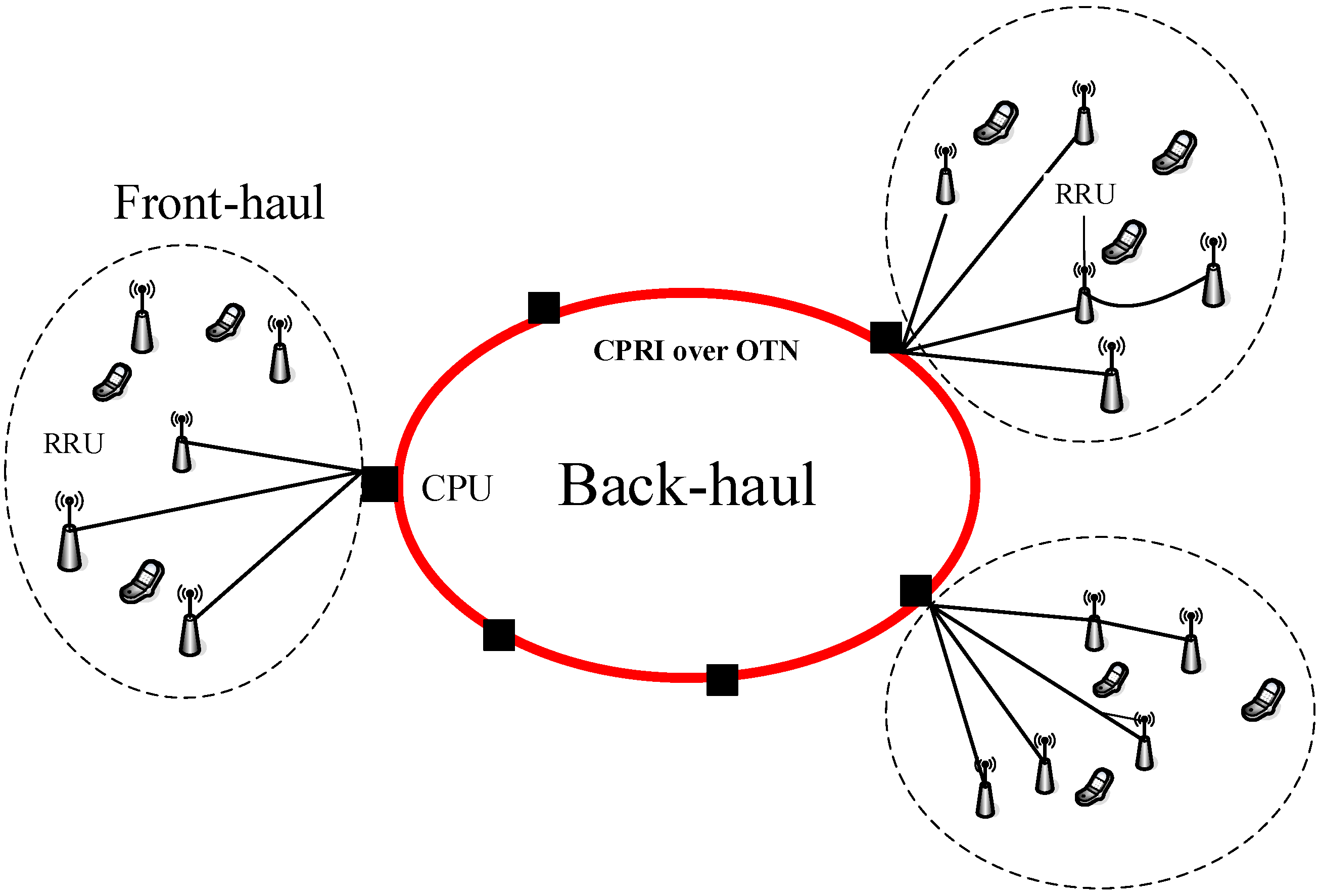
etc., combined with advanced applications, is requiring high capacity heterogeneous wireless networks. The current and future infrastructure of wireless access network is shown in
Figure 1, consisting of back-haul and front-haul transmission systems. Generally speaking, the back-haul transmission system is mainly based on high capacity digital fiber transmission, which has been investigated for decades.
Figure 1.
Schematic of radio access networks including back-haul and front-haul two transmission systems. CPRI: Common Public Radio Interface, OTN: Optical transport network, RRU: remote radio unit, CPU: central process unit.
Figure 1.
Schematic of radio access networks including back-haul and front-haul two transmission systems. CPRI: Common Public Radio Interface, OTN: Optical transport network, RRU: remote radio unit, CPU: central process unit.
Traditional techniques for RF and wireless signals distributed to antenna towers, i.e., the front-haul transmission systems, are based on narrow band analog RF transmission over coaxial cable, digital fiber transmission, narrow band analog point to point microwave transmission, and narrow band analog radio over fiber (RoF) transmission, etc. Microwave coaxial cable is too costly and high RF signals suffer from high loss in the cable, and also the cable bandwidth may not be sufficient for the future broadband RF/wireless signal distribution. Compared with microwave coaxial cable, optical fiber has features of extremely broad bandwidth, low cost, low loss, lightweight, safety, and immunity to electromagnetic interference. Digital signal fiber transmission, a matured technology, has been used widely for digital signal transmission, but has a serious drawback for RF/wireless signal distribution: The antenna tower site, i.e., remote radio unit (RRU), is very complicated since digital to/from analog signal processing is required. Microwave point-to-point transmission is more suitable for between buildings in dense cities, and may not be good for long distance and high capacity RF/wireless signal transmission.
Broadband RoF transmission system is an appropriate solution for the front-haul in broadband wireless access. RoF is to directly transmit analog RF/wireless signals over fiber from central process unit (CPU) to RRU, and vice versa, which has been used since 1990s for the narrow band RF/wireless signal distribution. Due to upcoming broadband applications, such as LTE and LTE advanced with the application of multiple input and multiple output (MIMO), RoF has become a hot and sustainable technology for the future cloud radio access networks (C-RAN). Since RoF is based on analog transmission, complicated signal processing can be located at CPU, and thus the RRUs are simplified. More importantly, when the RoF is used, the front-haul transmission is transparent to RF/wireless bit rates, RF/wireless carrier frequencies, and also wireless protocols. The transparent infrastructure and centralization not only make replacement and maintenance easier, but also dynamic cloud access is achievable. This is the main reason why the RoF has been re-visited by academia and industries recently.
Unfortunately, RoF transmission is based on optical subcarrier modulation and therefore is susceptible to nonlinear distortion. Therefore, suppression of nonlinear distortion,
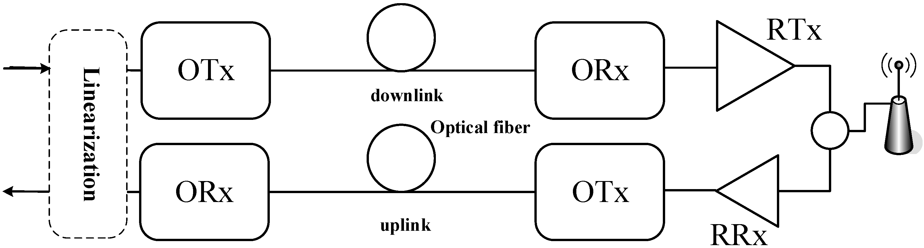
i.e., linearization, is the key for the successful application of RoF transmission to the broadband front-haul. Nonlinear distortion in RoF transmission is caused by nonlinear characteristics of microwave and optical transmission in RoF transmission systems. An RoF based front-haul transmission system is shown in
Figure 2. Two main sources of nonlinearities in the front-haul are nonlinearities of optical modulation at optical transmitter (OTx) and RF power amplification at radio transmitter (RTx). The other components may also introduce nonlinearities, such as low noise RF amplifiers, and photodiodes,
etc. Nonlinearities can generate spurious cross-talks that may overlap with transmitted RF/wireless signals, so that the transmission performance is degraded and the transmission system performance cannot conform to the standards of the applications.
Figure 2.
Schematic of RoF based front-haul transmission. OTx: optical transmitter, ORx: optical receiver, RTx: radio transmitter (RF power amplifier), and RRx: radio receiver (low noise amplifier).
Figure 2.
Schematic of RoF based front-haul transmission. OTx: optical transmitter, ORx: optical receiver, RTx: radio transmitter (RF power amplifier), and RRx: radio receiver (low noise amplifier).
Up to date, third order nonlinearity has been considered only. This is because some of the intermodulation distortion (IMD) components generated by the third order nonlinearity certainly fall in the passband of RF/wireless signals. However, when broadband and/or multi-band RF/wireless signals, which have been suggested by LTE-advanced, are transmitted, second order nonlinearity may also generate spurious crosstalk components that overlap with the transmitted RF/wireless signals. Consequently, both third and second order nonlinearity should be suppressed in RoF transmission.
For RoF downlinks in
Figure 2, the main sources of nonlinearities stem from optical subcarrier modulation at CPU and RF power amplifier at RRU. While for RoF uplinks in
Figure 2, the main sources of nonlinearities originate from optical subcarrier modulation at RRU. The rest of the components also introduce nonlinearities, but typically very small compared to the above.
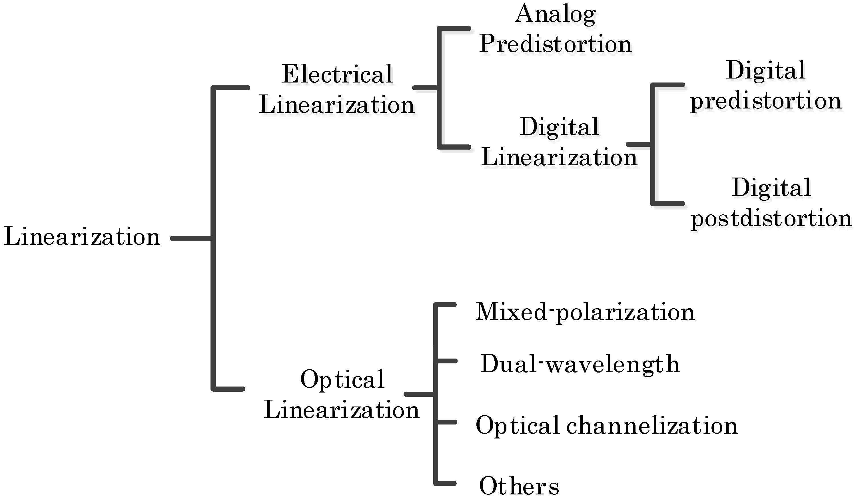
Figure 3 summarizes the linearization technologies that have been developed. Electrical and optical linearization means the implementation is completed in electrical and optical domains, respectively. Predistortion means that a spurious distortion is first generated and then is used to suppress the transmission-generated distortion. Post-distortion is opposite to predistortion in process sequence. Optical linearization can be considered pre-distortion. Next, we will discuss these linearization techniques separately.
Figure 3.
Linearization techniques.
Figure 3.
Linearization techniques.
2. Electrical linearization
Electrical linearization consists of analog predistortion and digital linearization. Digital linearization is given in
Section 4. In this section, we focus on analog predistortion circuit for linearization. Analog predistortion circuits have been designed to suppress third order IMD (IMD3) generated by RoF transmission [
1,
2,
3,
4,
5,
6,
7].
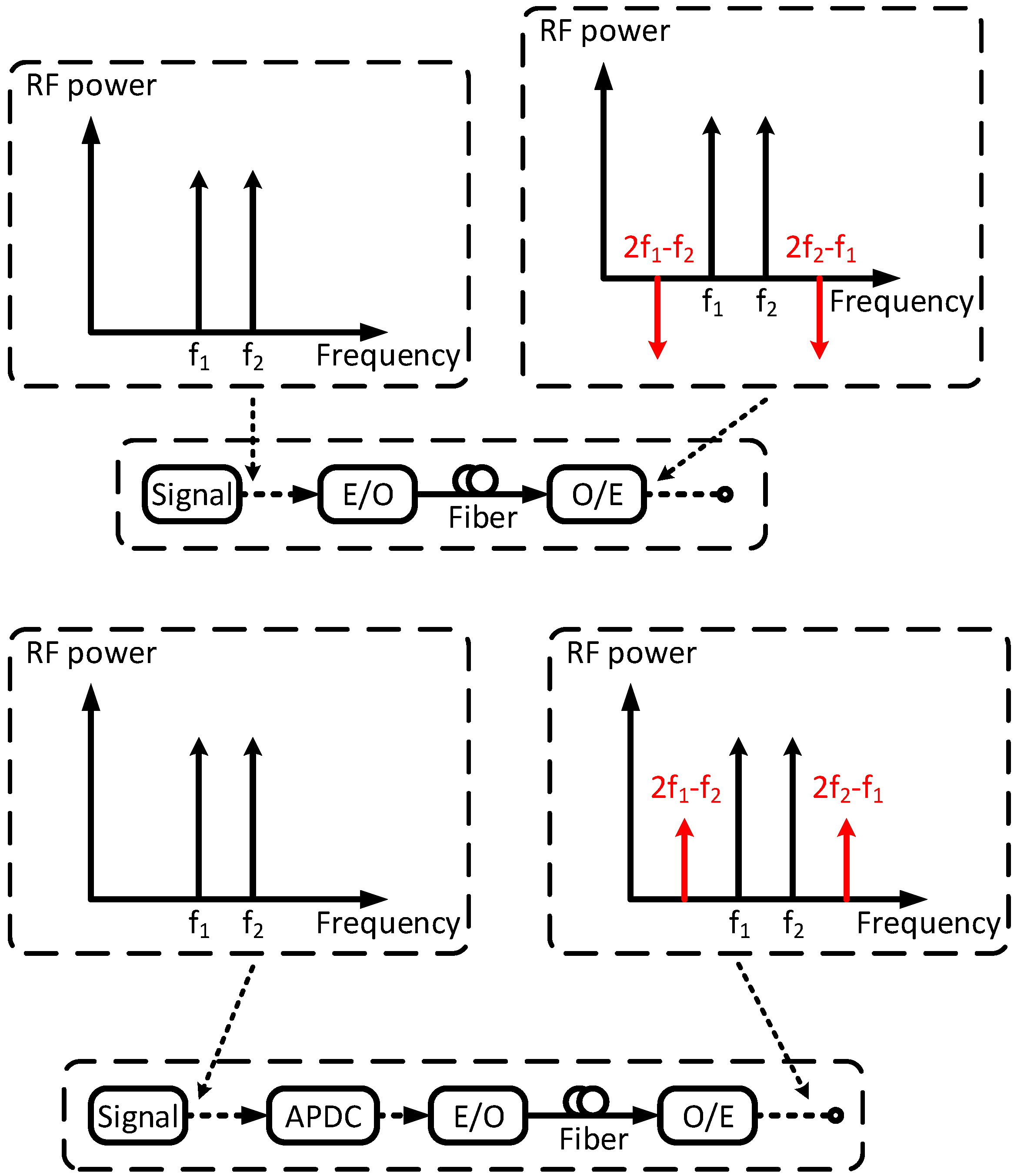
Figure 4 shows the principle diagram of linearization using analog predistortion circuit. Only IMD3 suppression is considered in this diagram. Suppose there are two RF/wireless signals at f
1 and f
2, which drive an electrical-to-optical (E/O) converter, such as direct modulation laser or an external modulator. The upper part of
Figure 4 shows the two generated spurious components at 2f
1–f
2 and 2f
2–f
1, introduced by third order nonlinearity of RoF transmission. Generally speaking, the optical-to-electrical (O/E) converter,
i.e., photodiode, and followed low noise RF amplifiers also induce the third order nonlinearity, but typically very small compared to optical subcarrier modulation. In principle, analog predistortion circuit can be used to suppress third order nonlinearity (such as IMD3) for the whole of RoF transmission, even including RF power amplifier [
8] and photodiode [
9] introduced third order nonlinearity. Usually, the generated IMD3 components are anti-phase with the RF/wireless signals, as shown in
Figure 4 upper part. The lower part of
Figure 4 shows schematic of linearization using the analog predistortion circuit. The analog predistortion circuit generates IMD3 components at 2f
1–f
2 and 2f
2–f
1, which are in-phase with the RF/wireless signals. Then after the RoF transmission, the IMD3 components generated by the RoF transmission and analog predistortion circuit generated IMD3 components will be cancelled by each other because they are antiphase. The RF/wireless signals remain unchanged except for some loss from the analog predistortion circuit.
Figure 4.
Principle diagram of linearization using analog predistortion circuit. APDC-analog predistortion circuit. E/O- electrical to optical and O/E- reversed.
Figure 4.
Principle diagram of linearization using analog predistortion circuit. APDC-analog predistortion circuit. E/O- electrical to optical and O/E- reversed.
It is understood that the accuracy of generated IMD3 phases by analog predistortion circuit is the key for the suppression. Generally speaking, generated IMD3 components are close to RF/wireless signals in frequency. Thus, it is not difficult to maintain the phases of the generated IMD3 components. However, the nonlinear distortion components generated by second order nonlinearity are usually far from the RF/wireless signals, thus difficult to maintain their relative phases to the RF/wireless signals over a large bandwidth. Therefore, it is difficult to have suppression of second order nonlinear distortion over a large bandwidth using analog predistortion circuit.
To realize broadband analog predistortion circuit to suppress IMD3 components, the phase and magnitude of IMD3 components must be managed precisely for the whole band. The RF/wireless signals and to-be-suppressed IMD3 components are better to have phase differences of less than 10°. Capacitor, inductor, and parasitics could introduce additional phase distortion. Also, it is required that magnitudes of the RF/wireless signals and to-be-suppressed IMD3 components do not change with the frequency in the whole band. The most important component in the analog predistortion circuit is the nonlinear generation sources, which mainly determine the linearization bandwidth. To achieve broadband linearization, it is found that use of one and/or two Schottky diodes is considered the best. The diode is able to generate all order nonlinearities due to its intrinsic V-I characteristic. Cut-off frequency of the diode can reach up to 3 THz. Therefore, analog predistortion circuit using Schottky diodes does not have bandwidth and upper frequency limitation.
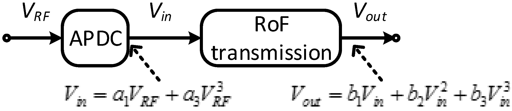
For the suppression of IMD3 components, a third order polynomial is used to approximate the RoF transmission. The input and output relationships of the analog predistortion circuit and the RoF transmission are given in
Figure 5, in which
V denotes voltage, and
a and
b are fitting coefficients of polynomials.
Figure 5.
Principle diagram of linearizing RoF transmission using analog predistortion circuit (APDC).
Figure 5.
Principle diagram of linearizing RoF transmission using analog predistortion circuit (APDC).
The output voltage after the analog predistortion circuit and RoF transmission can be described as
It can be seen that the third order nonlinear distortion components are removed at the output of RoF transmission if the condition
is satisfied. The analog predistortion circuit can be used to linearize directly and externally modulated RoF transmission. Generally speaking, the condition
b1/
b3 < 0 is satisfied for almost all RoF transmissions. This condition means the first and third order components generated by the RoF transmission are out of phase with each other (nπ phase difference,
n = 1,3,5…). Thus, to suppress the third order nonlinear components and unchange the first order linear components, the generated first (RF/wireless signals) and third order components by the analog predistortion circuit must be in phase with each other (2 nπ phase difference,
n = 0,1,2…).
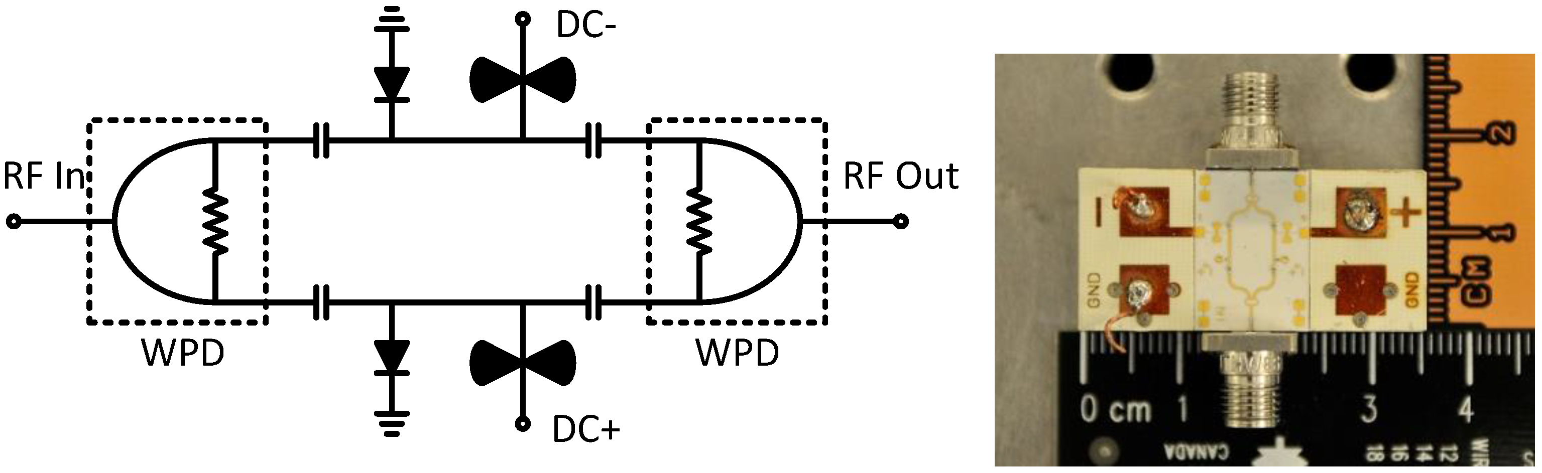
To verify the linearization using analog predistortion circuit, a broadband analog predistortion circuit [
6] using two zero bias GaAs beam lead diodes was designed and experimentally tested. The schematic of the analog predistortion circuit and the fabricated prototype is given in
Figure 6. The analog predistortion circuit consists of two symmetrical branches with two diodes that are in anti-parallel, so that even order components are eliminated at the output of the analog predistortion circuit. The diodes generate third order nonlinear components, which are in-phase with the RF/wireless signals. The magnitudes of the generated nonlinear components from the analog predistortion circuit are adjusted by tuning the bias currents of the analog predistortion circuit. The tested analog predistortion circuit is biased at 2.6 mA from 7 to 11 GHz and 1.1 mA from 12 to 18 GHz. The current is adjusted due to more loss induced by the analog predistortion circuit from 7 to 11 GHz.
Figure 6.
Schematic of the analog predistortion circuit and fabricated prototype.
Figure 6.
Schematic of the analog predistortion circuit and fabricated prototype.
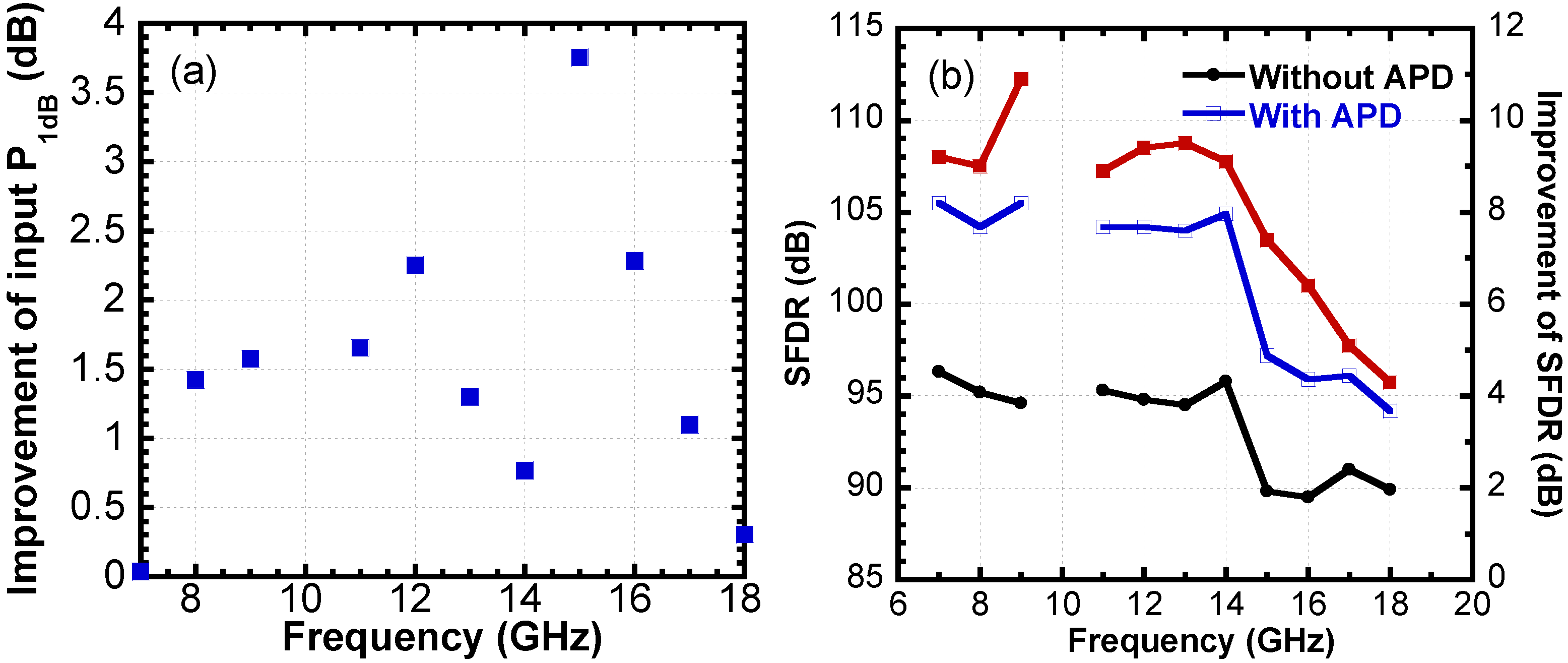
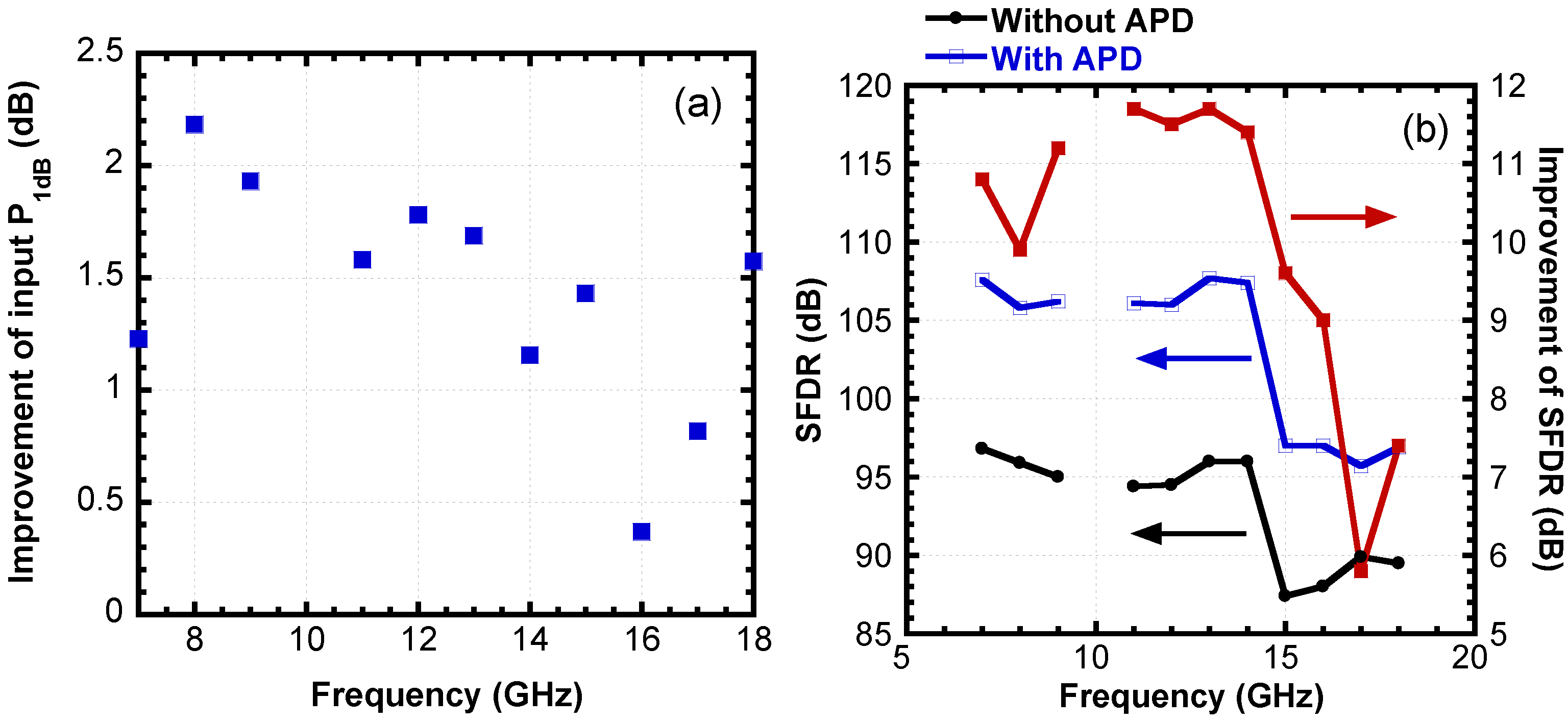
To evaluate the analog predistortion circuit, the input power at 1 dB compression point (P
1dB) without and with the analog predistortion circuit is measured. In the RoF system, a Mach-Zehnder modulator (MZM) is employed and biased at its quadrature to achieve optical single sideband modulation (SSB). The analog predistortion circuit is measured from 7 to 18 GHz. The input P
1dB is enhanced to more than −9 dBm by using the analog predistortion. Considering the insertion loss by the analog predistortion circuit, effective improvement of input P
1dB is given in
Figure 7a. It is shown that the input P
1dB is improved by more than 1.1 dB from 7 to 16 GHz. The decrease of effective improvement from 16 to 17 GHz is caused by the phase distortion. The improvement of input P
1dB illustrates that the RoF system is linearized from 7 to 18 GHz.
Figure 7.
(a) Effective improvement of input P1dB; (b) SFDRs without and with the analog predistortion and improvement of SFDR. MZM is used.
Figure 7.
(a) Effective improvement of input P1dB; (b) SFDRs without and with the analog predistortion and improvement of SFDR. MZM is used.
Moreover, a two-tone test is employed to measure the suppression of IMD3. Frequency spacing is 4 MHz. It is found the IMD3 is suppressed and the RoF transmission is limited by fifth order IMD (IMD5). This illustrates the IMD3 is eliminated and IMD5 finally becomes dominant. The measured spurious-free dynamic ranges (SFDR) and improvements
versus frequency are given in
Figure 7b. It can be seen that the analog predistortion improves the SFDR by more than 9.9 dB from 7 to 14 GHz, and more than 5.8 dB from 15 to 18 GHz.
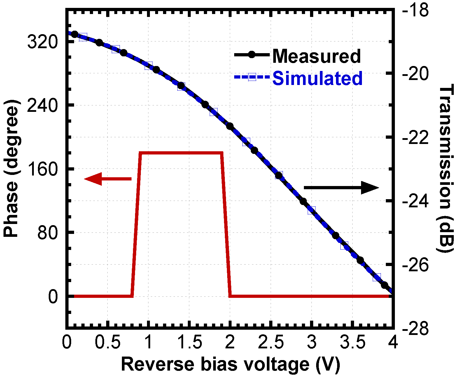
The analog predistortion circuit is also verified in an RoF system using EAM [
7]. A 40 Gbit/s electro-absorption modulator (EAM) is used. Transmission of the EAM, its fitting curve, and phase difference between the generated RF/wireless signals and IMD3 components from the EAM are given in
Figure 8. A polynomial of fifth order is used to approximate the transmission. The generated RF/wireless signals and IMD3 from MZM are always anti-phase. Unlike MZM, the phases of generated RF/wireless signals and IMD3 components from our considered EAM depend on its bias voltage. The phase differences between the RF/wireless signals and IMD3 components are calculated through the fitting curve.
Figure 8 shows that the phase difference is 180° for the bias voltage from −0.9 to −1.9 V, and it is 0° for the other bias voltages. The analog predistortion circuit generates only in-phase IMD3 components no matter of its bias current, so the RoF transmission using this EAM can be linearized for the bias voltages from −0.9 to −1.9 V only. In the experiment, the bias voltage is set to −1.5 V.
Figure 8.
Transmission of EAM, its simulated fitting curve, and phase difference between the generated RF/wireless signals and IMD3 components from the EAM.
Figure 8.
Transmission of EAM, its simulated fitting curve, and phase difference between the generated RF/wireless signals and IMD3 components from the EAM.
The measured improvement of input P
1dB is shown in
Figure 9a. The effective input power to the EAM is measured considering the insertion loss of the analog predistortion circuit. The input P
1dB without and with using the analog predistortion circuit is given.
Figure 9a shows that an improvement of about 1 dB and above by using the analog predistortion circuit is obtained for input P
1dB from 8 to 17 GHz. The reasons of low improvement at 7 and 18 GHz are high power of even order IMD generated in the RoF system and high power of the IMD5 generated by the analog predistortion circuit.
The improvement of SFDR is measured with and without using the analog predistortion circuit. The IMD3 generated by the RoF transmission system is cancelled using the analog predistortion circuit, and the RoF transmission becomes fifth order limited. Thus, the analog predistortion improves the SFDR by more than ~9 dB from 7 to 14 GHz and more than ~4 dB from 15 to 18 GHz.
As shown in
Figure 6, the analog predistortion circuit is simple, stable, and of small size and low cost. By adjusting the DC bias of the analog predistortion circuit, linearization can be achieved in all externally and directly modulated RoF transmission systems. Moreover, the low bias currents lead to very low power consumption. Typically speaking, 10 dB improvement of SFDR can be achieved in broadband RoF transmission. By cascading two analog predistortion circuits, it is possible to have IMD3 and IMD5 both suppressed.
Figure 9.
(a) Effective improvement of input P1dB; (b) SFDRs with and without the analog predistortion and improvement of SFDR. EAM is used.
Figure 9.
(a) Effective improvement of input P1dB; (b) SFDRs with and without the analog predistortion and improvement of SFDR. EAM is used.
Furthermore, analog predistortion circuit can be also used for linearization of RF power amplifiers [
8] and photodiodes [
9]. Moreover, analog predistortion circuits can be implemented without using Schottky diodes, but the linearization bandwidth may be limited [
2,
3,
4,
5].
3. Optical Linearization
As shown in
Figure 3, optical linearization consists of mixed-polarization [
10,
11,
12,
13,
14], dual wavelength [
15,
16], and optical channelization [
17,
18], as well as the others.
The principle of all optical linearization methods except optical channelization are almost similar, namely the nonlinear components generated by RoF transmission at two operation points can be cancelled by each other, but linear components (RF/wireless signals) are not suppressed. Therefore, optical linearization can be used to suppress both second- and third-order nonlinearities.
Mixed-polarization means that, to use TE and TM transmission characteristics of RoF transmission, the nonlinear components generated by TE and TM transmission are cancelled by each other, if the nonlinear components from the TE and TM transmission can have out of phase (nπ phase difference,
n = 1,3,5…). Therefore, the TE and TM characteristics must be different, which means that the RoF transmission must be polarization dependent, such as RoF transmission using polarization dependent MZM or EAM. Using the mixed-polarization linearization, both second and third order nonlinear distortion can be significantly suppressed by appropriately adjusting polarization angles. However, the linear components (RF/wireless signals) may be also suppressed to some extent, and the suppression is strongly dependent on the TE and TM characteristics of MZM or EAM. For example, using LiNbO
3 MZM, an addition loss of 13 dB may be introduced by the mixed polarization [
12]. When using GaAs MZM, the TE and TM transmission characteristics that have opposite phase modulation indices are quite different from LiNbO
3 MZM, and thus the additional loss may not be introduced for RF/wireless signals [
19,
20]. However, the mixed-polarization linearization may not be used to suppress both second and third order nonlinearities at the same time.
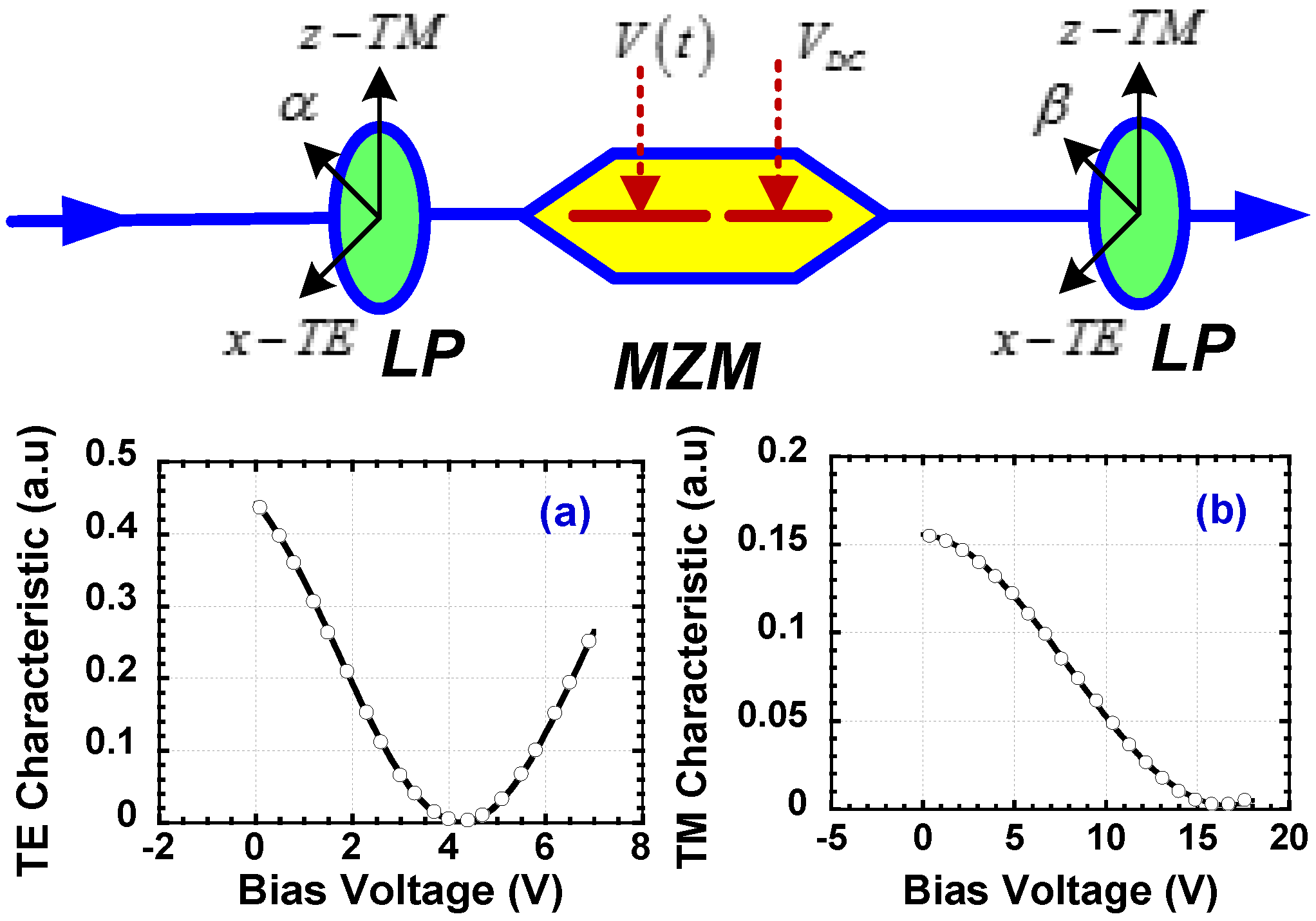
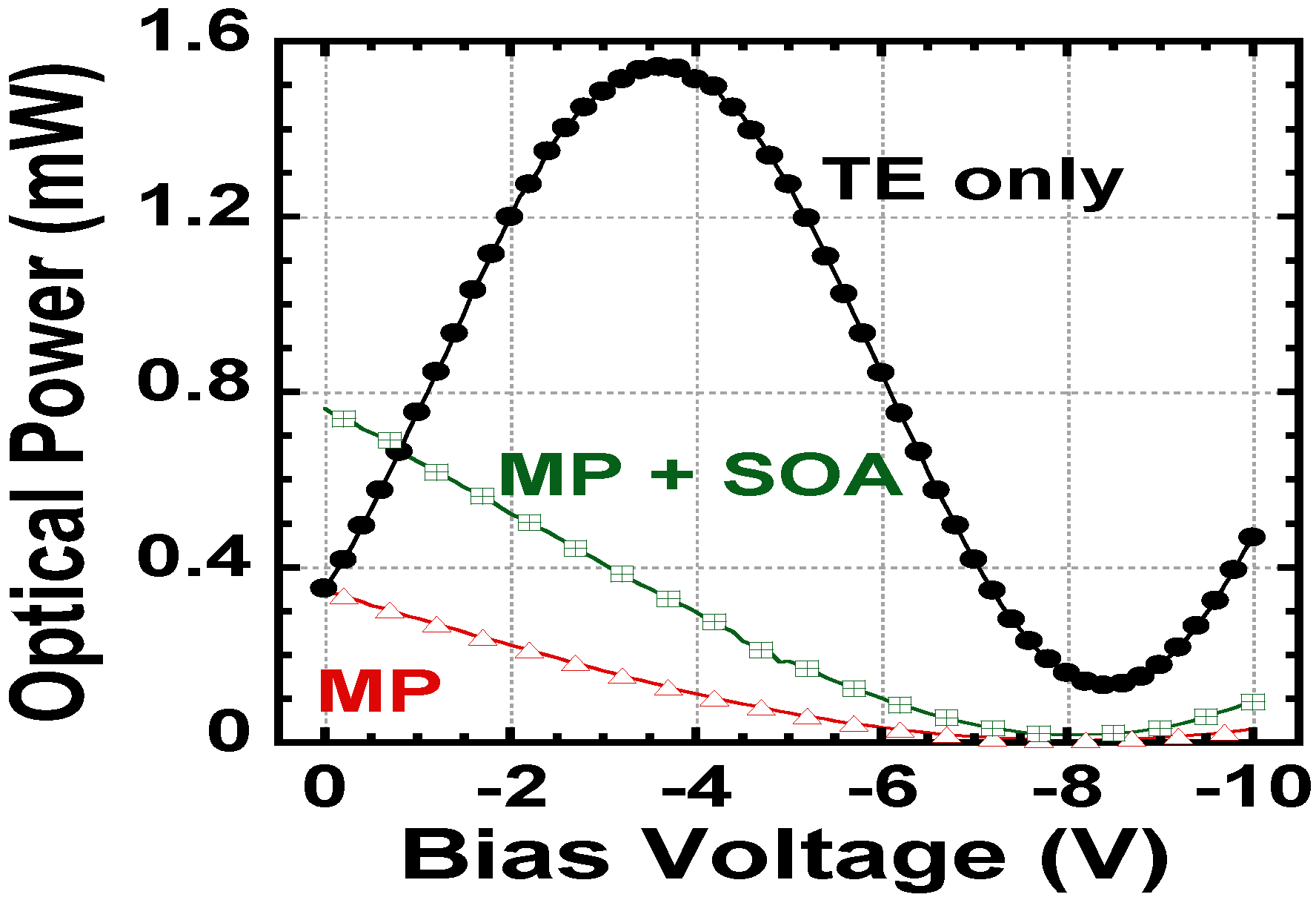
Figure 10 shows the configuration of mixed polarization to linearize an MZM, consisting of a front and rear polarization linearizer located at input and output of the MZM. The two polarization angles, α and β, are dependent on TE and TM transmission characteristics of the MZM, and the measured TE and TM characteristics are also shown in
Figure 10 as an example. The rear polarization linearizer can be replaced by a saturated semiconductor optical amplifier (SOA) [
21]. The comparisons of RoF transmission characteristics for three cases, without using optical linearization, using mixed-polarization, and using mixed polarization combined with a saturated SOA, are shown in
Figure 11. It is seen that a conventional MZM has an almost sinusoidal transmission, but by using mixed-polarization (MP) linearization the transmission is almost linear over a certain range of drive voltage. Further by combining with a saturated SOA, the transmission linearity is further improved. Typically speaking, SFDR improvement by mixed-polarization is more than 10 dB. Because of linearization implemented in optical domain, the linearization bandwidth is only limited by optical modulator modulation bandwidth.
Figure 10.
Mixed-polarization linearization configuration to linearize an MZM with measured TE and TM transmission characteristics.
Figure 10.
Mixed-polarization linearization configuration to linearize an MZM with measured TE and TM transmission characteristics.
Figure 11.
Measured transmission characteristics for three cases: conventional MZM without linearization, MZM linearized by mixed-polarization (MP), and MZM linearized by MP combined with a saturated SOA.
Figure 11.
Measured transmission characteristics for three cases: conventional MZM without linearization, MZM linearized by mixed-polarization (MP), and MZM linearized by MP combined with a saturated SOA.
Similarly, the principle of dual-wavelength linearization (DWL) is given as follows: Nonlinear distortion components generated at two wavelengths λ
1 and λ
2 can be cancelled by each other [
15]. Therefore, it is required that the transmission characteristics of RoF transmission are different at λ
1 and λ
2,
i.e., wavelength dependent transmission. The nonlinear components generated at λ
1 and λ
2 can be suppressed if they are anti-phase with each other, while the linear components (RF/wireless signals) can be improved if they are in phase. Fortunately, both MZM and EAM have wavelength dependent transmission characteristics. In other words, when a RoF system uses one of those two external modulators, the RoF transmission characteristic becomes wavelength dependent. For example, we consider a RoF transmission using an EAM. Lights emitted from two lasers with wavelengths λ
1 and λ
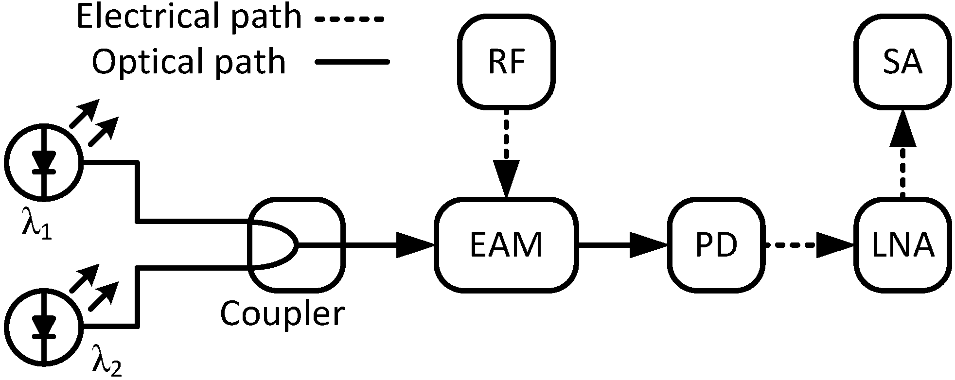
2 are coupled and transmitted to an EAM, which is used for optical subcarrier modulation. The two lights experience different modulation characteristics in the EAM so that RF/wireless signals and nonlinear components at the two lights are generated. The two lights are incoherent and carry their own RF/wireless signals and nonlinear components. After photodetection, the two groups of the RF /wireless signals and nonlinear components at the same frequencies are obtained. If the phases of the two RF/wireless signals and nonlinear components are iphase and anti-phase, respectively, the RF /wireless signals and nonlinear components will be improved and suppressed in power, respectively. By adjusting the power ratio of the two lasers, improvement of the RF/wireless signals and suppression of nonlinear components can be optimized. The schematic of the DWL technique is given in
Figure 12.
Figure 12.
Schematic of the dual-wavelength linearization technique.
Figure 12.
Schematic of the dual-wavelength linearization technique.
To verify the DWL technique, the SFDR and output P
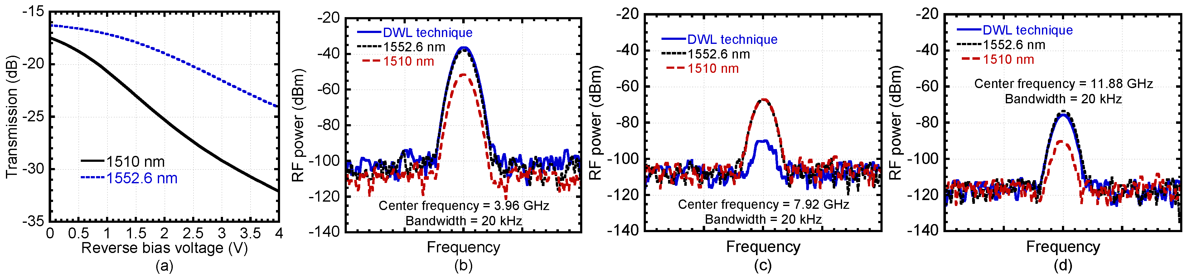
1dB were measured. Single-tone test is employed to check the suppression of nonlinearities. A C-band EAM is used for optical subcarrier modulation. The transmission characteristics of the EAM are given in
Figure 13a. It can be seen the transmission at 1510 nm is around 5 dB lower than that at 1552.6 nm because the EAM is designed for C-band. Obviously, the two transmissions are different that illustrates the wavelength dependence of the EAM. The EAM is biased at −1.5 V. An RF signal generator is used to generate a 3.96 GHz RF carrier. Power of the 1510 nm laser is adjusted to get the minimum second order harmonic distortion (HD2).
Figure 13b shows that the power of the output RF signal at 1510 nm is 13.6 dB lower than that at 1552.6 nm. So the 1510 nm laser cannot be used individually for this EAM. Compared to using a single 1552.6 nm laser, the power of the RF signal is improved by 1.6 dB; and the power of the HD2 is suppressed by 23 dB. The power of the third order harmonic distortion (HD3) is suppressed by 2.1 dB by using the DWL technique. It is shown that the HD2 and HD3 are suppressed simultaneously. Both the HD2s and HD3s carried by the two lights are anti-phase with each other respectively at the bias voltage of −1.5 V.
Figure 13.
(a) Measured transmission characteristics of the EAM, and RF spectra of (b) output RF signals; (c) HD2; and (d) HD3.
Figure 13.
(a) Measured transmission characteristics of the EAM, and RF spectra of (b) output RF signals; (c) HD2; and (d) HD3.
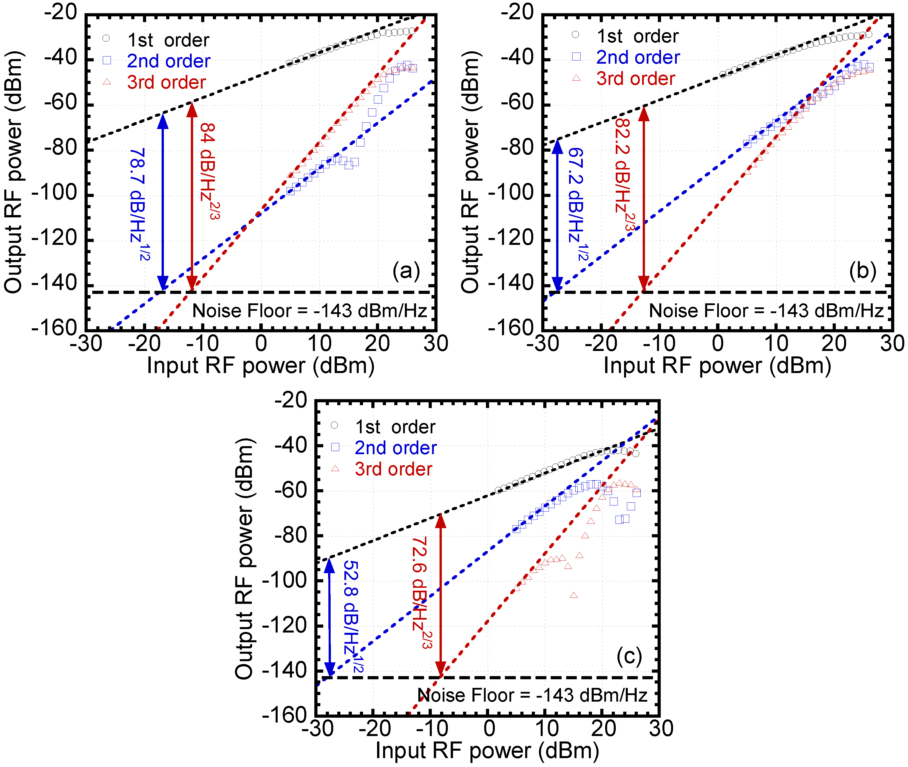
SFDRs with respect to HD2 or HD3,
i.e., SFDR
2 and SFDR
3, are measured and given in
Figure 14. SFDR
2 improvements of 11.5 dB and 25.9 dB are achieved compared to using a single laser at 1552.6 nm and 1510 nm, respectively. It also can be seen the SFDR
3 is improved by 1.8 dB and 11.4 dB compared to using single laser at 1552.6 nm and 1510 nm, respectively. The output RF/wireless signal is also increased by the DWL technique.
Figure 14.
Measured SFDRs using (a) the DWL; (b) the 1552.6 nm laser; and (c) the 1510 nm laser.
Figure 14.
Measured SFDRs using (a) the DWL; (b) the 1552.6 nm laser; and (c) the 1510 nm laser.
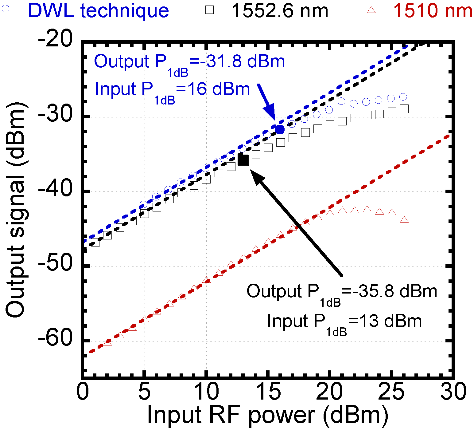
The measured output signals using the DWL technique, single laser at 1552.6 nm, and 1510 nm
versus input RF power are given in
Figure 15. It is shown that the output RF signal at 1510 nm has slight gain expansion, which is used to compensate for gain compression of output RF signal at 1552.6 nm. The input P
1dB is improved from 13 to 16 dBm and output P
1dB is improved from −35.8 to −31.8 dBm by the DWL technique. Three-decibel improvement of input P
1dB and 4 dB improvement of output P
1dB are obtained.
Figure 15.
Measured output RF signals using DWL technique, single laser at 1552.6 nm, and single laser at 1510 nm.
Figure 15.
Measured output RF signals using DWL technique, single laser at 1552.6 nm, and single laser at 1510 nm.
Optical channelization combined with coherent detection can be used for linearization of RoF transmission [
17,
18]. The principle is very simple: extracted nonlinear baseband signal is added to transmitted optical signal by another optical modulation and thus optical predistortion is generated. By coherent detection, the nonlinear distortion components may be cancelled if they are anti-phase. Simulation shows 30 dB suppression of nonlinearity [
17]. Alternatively, nonlinear distortion signal is individually recovered, first by direct detection at receiver, and then the optically coherent detected RF/wireless signal is digitally processed combined with the nonlinear distortion signal to suppress nonlinear distortion of RoF transmission [
18]. Experimental demonstration showed that IMD3 can be suppressed by 25 dB. The optical channelization technique may be more applicable to ultra broadband RF signals and special applications.
The other optical linearization techniques have similar principles as the mixed polarization and dual wavelength, such as using two cascading MZMs [
22,
23,
24], two parallel MZMs [
25,
26],
etc.Typically speaking, optical linearization can provide an improvement of SFDR by more than 10 dB, and can achieve suppression of nonlinear distortion over the whole RF modulation bandwidth of the external modulator.
4. Digital Linearization
Digital linearization includes conventional digital predistortion (DPD) and digital post processing (DPP) distortion. DPD has been developed for decades, to suppress third order nonlinear distortion generated by RF power amplifiers [
27]. Digital linearization uses analog-to-digital converter (ADC) to sample analog signals and linearize transmission by digital signal processing (DSP). Generally speaking, the current digital linearization is limited to 20 MHz bandwidth, and can be extended to 100 MHz bandwidth. Technically, it is now possible to achieve wideband, greater than 1 GHz bandwidth. However, the required DSP is complicated and power consumption is huge, beyond practical applications. To reduce the DSP requirements, multi-band DPD techniques have been developed recently, in which only RF/wireless signals occupied bandwidth is processed [
28]. Alternatively, novel RF amplifiers and transmitters are being developed to reduce the requirements of linearization, such as Doherty amplifiers and 1-bit RF transmitters [
29,
30].
In order to use DPD for broadband RoF downlinks and DPP for broadband RoF uplinks, both located in CPU as shown in
Figure 3, it is required to simplify the currently developed digital techniques that are being used for RF power amplifiers and also improve the linearization bandwidth [
31,
32,
33].
The principle of digital pre-linearization technique is that a predistorter is used to generate opposite nonlinearity characteristic digitally to compensate for the nonlinearity of RoF transmission. When broadband signals are transmitted over RoF, memory effect in RoF transmission has to be considered. So, memoryless polynomial is not sufficient to model RoF transmission. More than 10-dB additional accuracy can be obtained when using a memory polynomial to estimate nonlinear behaviors than using memoryless polynomial in RoF transmission [
34]. Volterra series is commonly considered to be an appropriate memory polynomial. Memory length and nonlinearity order of the memory polynomial are related to the performance and complexity of the digital linearization. Up to fifth order nonlinearity may be sufficient for the model. Even order nonlinearities also need to be considered because even order nonlinearities also contribute to the generation of odd order IMDs. Memory length of two may be adequate to model memory effect of RoF transmission, dependent on time delay in considered bandwidth. When higher nonlinearity order and memory length are used, the accuracy is improved slightly but much more modeling coefficients need to be extracted. This dramatically increases complexity and calculation time of digital linearization. Moreover, when the nonlinearity is increased, the accuracy of the model is decreased.
The DPD technique uses feedback of nonlinearity information of the RoF transmission to generate a distorter. By sampling the input and output data of RoF transmission without DPD, a predistorter with inversed nonlinearity characteristic can be generated. A memory polynomial can be used to approximate the predistorter. To obtain the coefficients of the memory polynomial, the input and output data of the RoF transmission is used as training output and input data of the predistorter, Gain of the RoF transmission need to be removed before the training input data is injected to the predistorter. Then, using the least-square error minimization method or other algorithms, the coefficients of the distorter model can be extracted and the predistorter is established. When up to fifth order nonlinearity is used in digital pre-linearization, more than 15 dB suppression of adjacent channel power (ACP) can be achieved [
35]. However, it requires at least five times the signal bandwidth for sampling.
Generally speaking, the digital pre-linearization provides the best performance than other linearization methods in specified limited bandwidth. Also, linearization efficiency is higher when several nonlinearities are linearized simultaneously. But, higher digitizer bandwidth is required to sample higher order nonlinearities. The bandwidth and cost limit the application of digital pre-linearization substantially.
Alternatively, digital post-linearization can be also applied. One method is to directly digitize the RF signals and implement linearization, all order nonlinear distortion components can be compressed significantly [
36]. Because nonlinearity information of RoF transmission is blind at receiver side, digital post-linearization has to use recursive sweep and monitor the ACP to find the optimum coefficients of memory polynomial, which degrades the linearization performance by about 3 dB [
37]. The disadvantage is that a high-speed digitizer is required, similar to DPD. The other method is to implement linearization in received baseband signals, and thus high-speed digitizer is not required. For example, Hammerstein decision feedback equalizer for linearizing concatenated fiber-wireless transmission has been investigated [
38]. Because of high speed signal processing required, this type of digital linearization can be only used in CPU, and thus this technique is only applicable for uplinks only. The advantage is that any order nonlinear distortion can be suppressed [
39], and more orders require more signal processing.
As shown in
Figure 2, in order to locate linearization in CPU and also have low complexity of linearization, baseband signal processing techniques, such as Hammerstein predistortion equalizer for downlinks and Hammerstein decision feedback equalizer for uplinks, may be more promising, which requires further intensive investigation.


