1. Introduction
Recently, the development of automobile electronics has led to an increase in the number of small motors installed in automobiles. More than 70% of small motors applied in automobiles are DC motors that are inexpensive and easy to control. However, DC motors have a fatal drawback in that their lifespan is limited due to the mechanical friction between the brushes and the commutator. Currently, as the production of small motors has become common, high motor performance such as durability and power density is sought after. Consequently, the DC motor has been replaced by a brushless DC motor (BLDC) with high power density and durability. However, as the electric vehicle market grows gradually, new problems have arisen due to stricter noise regulations. With the switch from internal combustion engine vehicles to electric vehicles, the noise of small motors, which had previously been masked by engine noise, emerges in electric vehicles.
In the past few years, many studies have been conducted on techniques to reduce vibration and noise in motors. Among them, the most renowned technologies are as follows: First, there are techniques for changing the core shape to make the magnetic flux density waveform of the air gap similar to a sinusoidal wave. For example, there are techniques for applying chambers and notches, eccentricities, and skews to the stator or rotor core [
1,
2,
3,
4]. Second, the combination of the number of poles, number of slots, and the winding pattern have changed [
5,
6,
7]. Finally, there is a technology that reduces the vibration and noise in the motor by adding harmonic components to the current in the controller [
8,
9,
10]. However, these technologies increase the production process, and require tight tolerance designs for precise applications [
11,
12,
13]. As a result, the production cost increases, and considerable time is expended at the design stage. In addition, the cogging torque cannot be eliminated unlike that of the slotless motor, due to the original structure of the conventional motor [
14,
15,
16]. Furthermore, these techniques reduce the back EMF constant of the motor and degrade the performance.
In this study, we introduced a BLDC slotless motor with toroidal winding (TSLM). Unlike a conventional motor (CM), in which a coil is wound around the stator tooth, in the TSLM, the coil is wound around a ring-type yoke in the circumferential direction. Toroidal winding is already widely used in transformers [
17,
18,
19]. However, the structure of the toroidal winding applied to the BLDC motor is obscure.
We explained the basic operating principle of the TSLM using the BLDC six-step sequences. We demonstrated the rotating magnetic field by indicating the magnetic field of the armature according to the sequence section. Moreover, we explained the flux linkage and back EMF waveforms by the permanent magnets according to the rotor position. Further, the air-gap flux density, flux linkage, and back EMF were calculated through the lumped-parameter circuit of the proposed slotless motor and were compared with the FEA results. Finally, the TSLM was manufactured and compared with the calculated and FEA results through testing.
2. Motor Configuration
2.1. Conventional Motor
As shown in
Figure 1a, in the case of the CM, the coil is wound by a winding machine inside the stator slot. Therefore, a space is required for the machine’s nozzle to enter the stator core, which is referred to as the slot opening. This appears repeatedly on the surface of the armature core by the number of slots and causes a magnetic reluctance variation according to the rotor position. As shown in Equation (1), cogging torque is generated as a result, and it appears as a period of the least common multiple (LCM) of the number of poles and number of slots.
where
is the air-gap flux,
is the air-gap magnetic reluctance,
is the position of the rotor,
is the number of slots in the stator, and
is the number of poles in the rotor.
As such, cogging torque is inevitably generated due to the fundamental teeth and slot structure of the CM. The generated cogging torque not only causes vibration and noise, but also adversely affects speed and position control during low-speed operations [
20,
21]. Techniques to reduce the cogging torque have been studied for many years, and they result in additional manufacturing processes and require tight tolerance designs. As a result, the productivity of mass production decreases due to the cost increase and time expended. In addition, these techniques reduce the back EMF constant of the motor, resulting in poor performance.
2.2. Proposed Slotless Motor
As shown in
Figure 1b, the TSLM has a ring-type armature core. The coil is wound circumferentially about the armature core. Accordingly, the coils contributing to the performance are placed inside and outside the yoke. Since slotless motors do not have slots or teeth, there is no magnetic reluctance variation depending on the position of the rotor. As result, the cogging torque is theoretically zero. There are certain advantages of slotless motors over slot motors [
22,
23,
24]:
Moreover, the TSLM has a much simpler structure than a conventional slotless motor with a complex coil structure, and the winding workability is easier than that of the CM.
The slotless motor has a much larger air gap than the CM because the coil is placed in the gap between the rotor and the stator. Unlike the CM, there are many factors to consider when designing slotless motors because when the coil diameter is increased, the air-gap length is also increased. Therefore, if the goal is to achieve high power density and efficiency, the CM is a more reasonable choice. Conversely, if quiet and precise driving conditions are the goal, a slotless motor that can effectively reduce vibration and noise without special design techniques is advantageous.
3. Principle of Operation
The TSLM differs from the CM mainly in the direction of flux linkage due to a different coil structure. As shown in
Figure 2, when the magnetization direction of the permanent magnet is taken as a reference, the magnetic flux of the CM is linked to the coil in the radial direction, and the magnetic flux of the TSLM is linked to the coil in the circumferential direction. To drive the motor, a rotating magnetic field must be generated when a three-phase alternating current is applied to the coil.
In this section, we explained the principle of generating a rotating magnetic field in the proposed slotless motor using a BLDC six-step inverter. In addition, we described the flux linkage by permanent magnets for each rotor position.
3.1. Rotation Field
First, we described the principle of generating a rotating magnetic field by armature current using a BLDC six-step inverter.
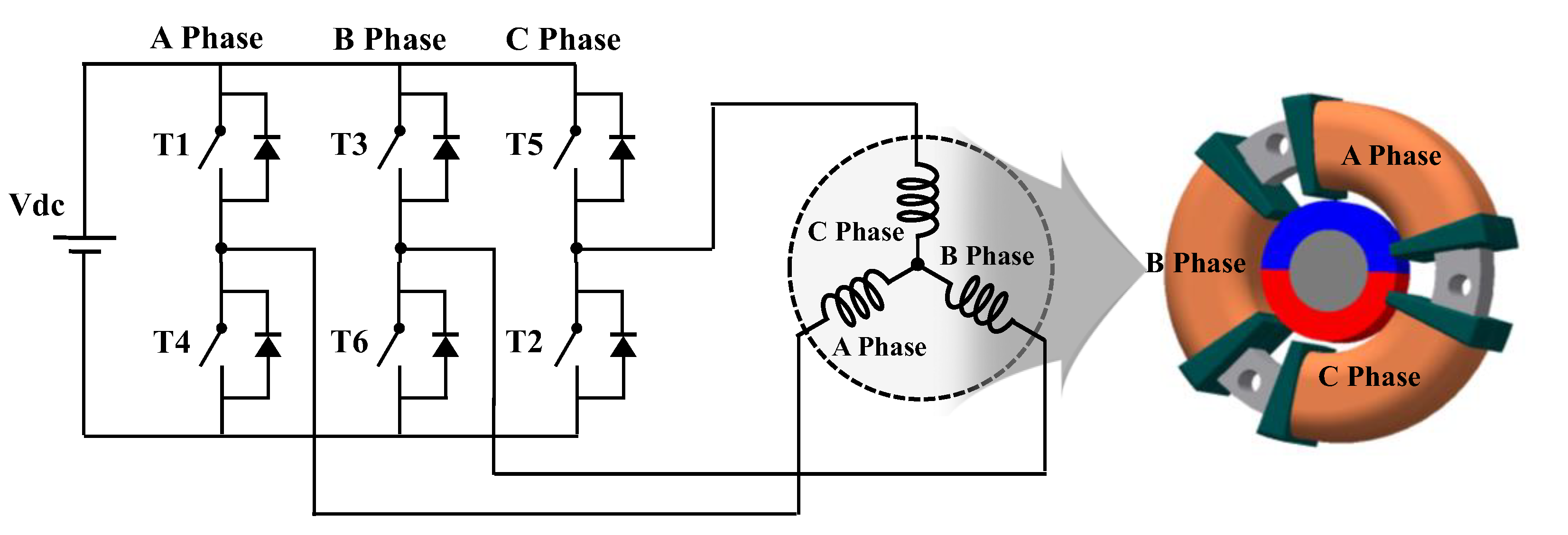
Figure 3 shows the circuit of a three-phase six-step inverter and a Y-connected slotless motor. Moreover, the Hall sensors are arranged at intervals of 120 degrees of electrical angle. For better understanding, a slotless motor with a 2-pole 3-coil bunch is taken as an example. As shown in
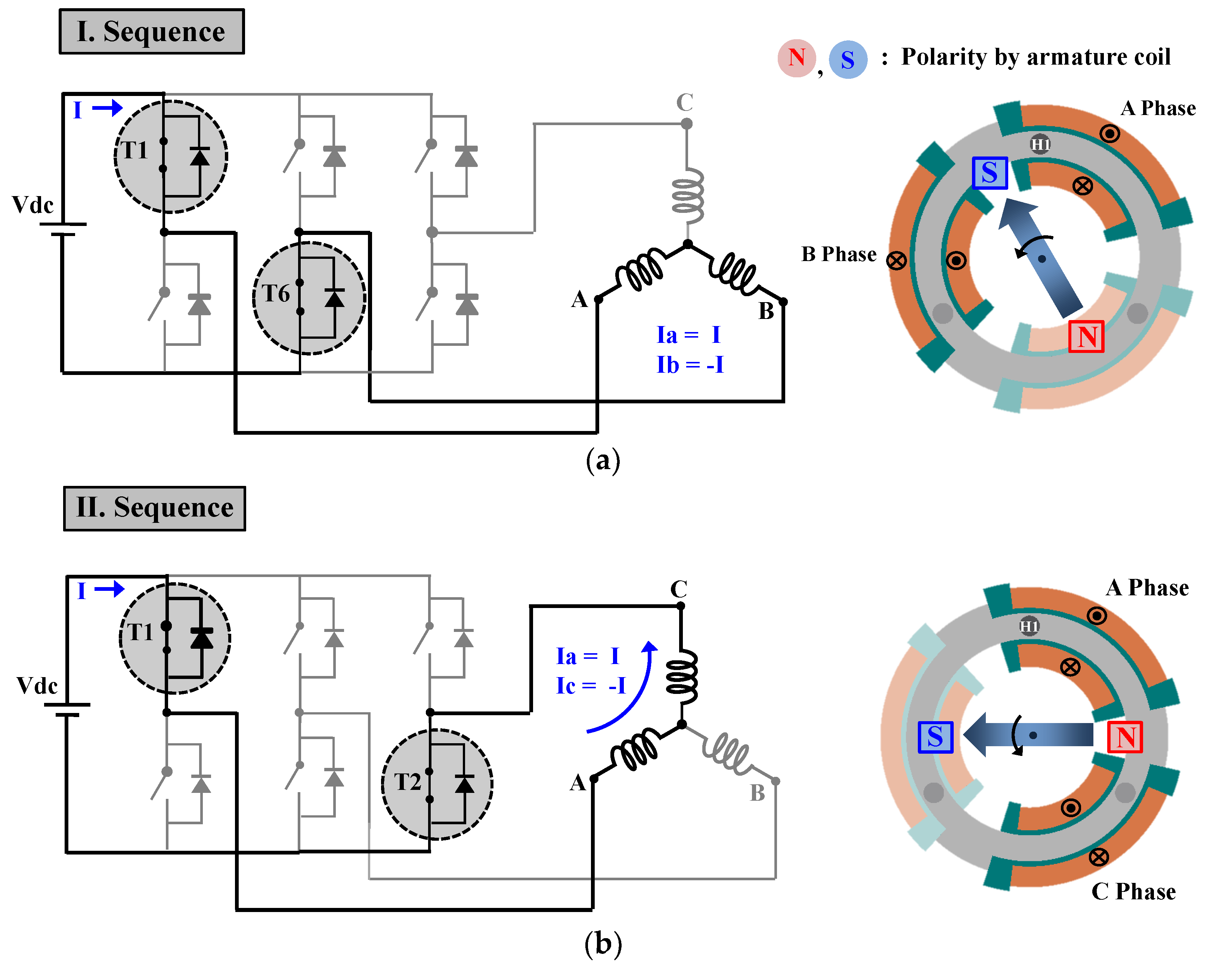
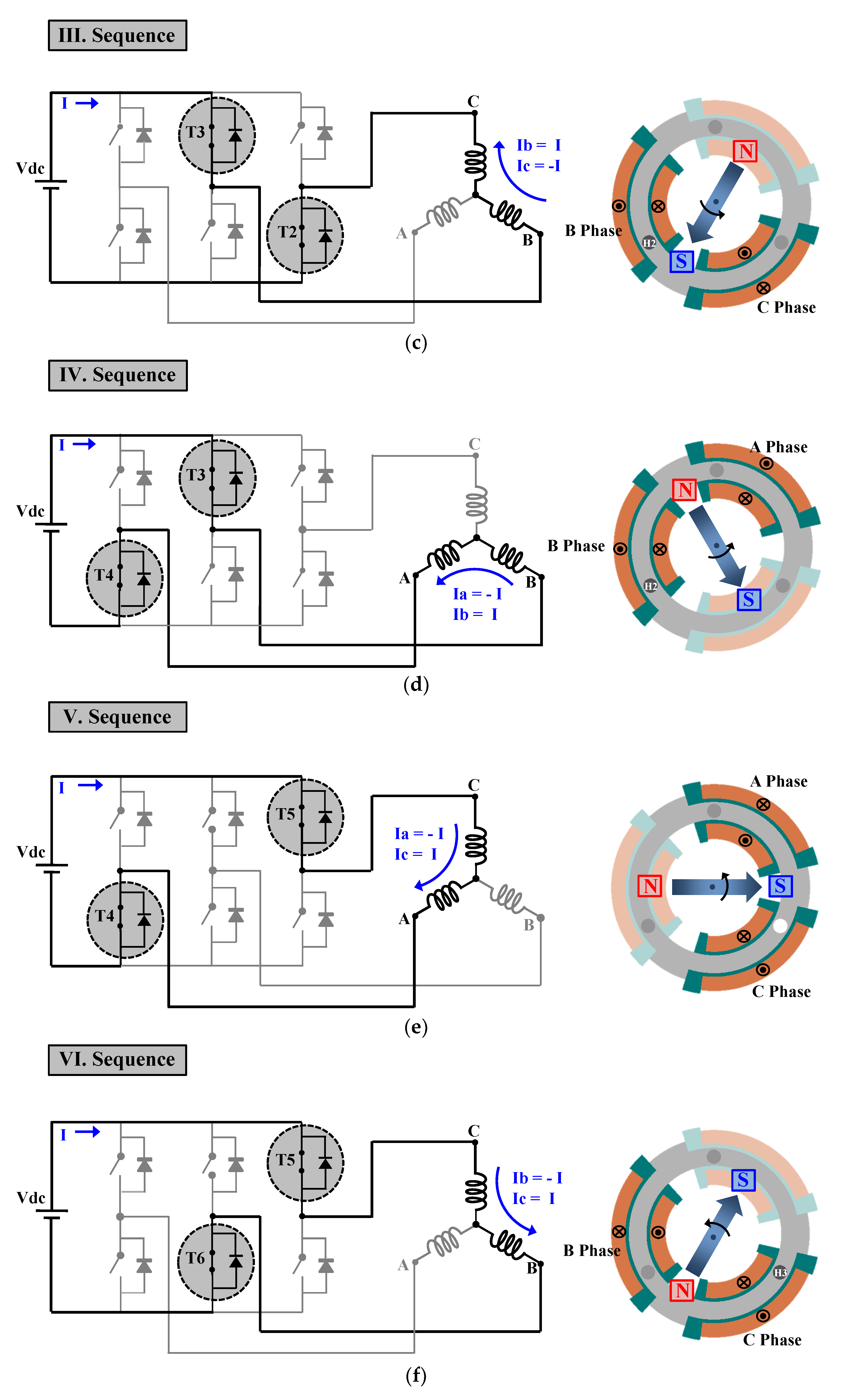
Table 1, the operating element can be divided into six sections as per the signal of the Hall sensor. For continuous rotation using the detected rotor position information, the inverter generates two phase currents to the stator coil. Therefore, the rotating magnetic field in the counterclockwise direction is generated according to the switching sequence of the six sections as shown in
Figure 4.
3.2. Flux Linkage by Magnet
The following describes the process in which the magnetic flux by the permanent magnet is linked to the A-phase coil. As shown in
Figure 5, when the rotor position is at 60 degrees and 240 degrees, the amount of magnetic flux entering the A-phase coil and the amount of outgoing magnetic flux are the same. That is, at this position, the total flux linkage of the A-phase coil becomes zero. When the rotor position is at 150 degrees, the amount of magnetic flux entering the A-phase coil reaches its peak, and when the rotor position is at 330 degrees, the magnetic flux exiting the A-phase coil reaches its lowest point. As a result, the magnetic flux linkage to the A-phase coil during one rotation of the rotor has a waveform that alternates between positive and negative values. The back EMF also has an alternating waveform that is 90 degrees ahead of the phase of the flux linkage.
4. Analytical Design
This section presents details of the numerical approach of the slotless motor proposed in this study. The various parts of the motor are represented using reluctances and magnetic sources. The motor can be expressed as a lumped-parameter magnetic circuit, and fundamental parameters can be quickly calculated using simple mathematical calculations [
25]. The air-gap flux density, winding factor, and flux linkage of the slotless motor were calculated using a lumped-parameter magnetic circuit, and were verified through the FEA.
4.1. Analytical Approach
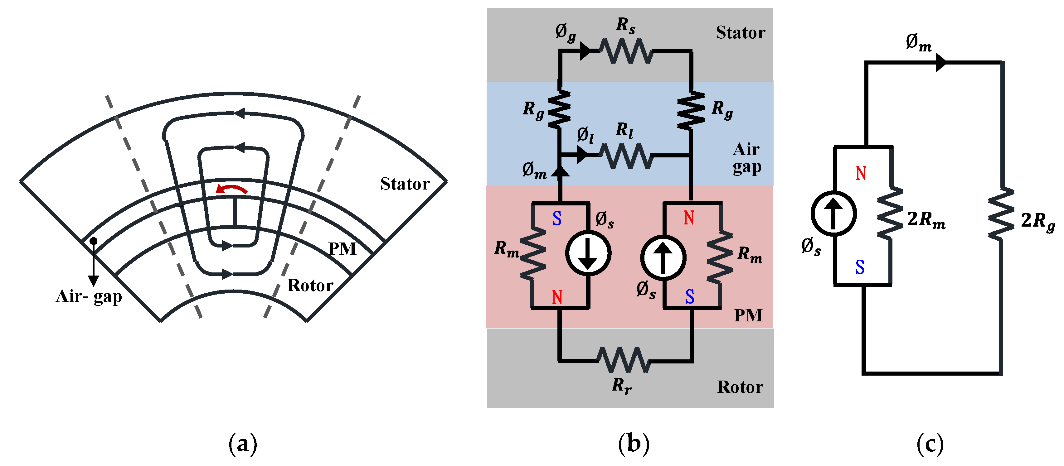
Consider the motor cross-section shown in
Figure 6a. For simplicity, the stator is shown without windings. For one-half of the North and South poles facing the air gap, this flux flow is illustrated by the flux path. Some magnetic flux jumps from one magnet to the next in the air gap without passing into the stator. The flux that follows this path is often called magnet leakage flux. In
Figure 6b, the rotor, stator, and air-gap areas are modeled simply as reluctances. The two half magnets are modeled as a flux source and associated magnet reluctance, with the direction of the flux source dictating the polarity of the magnet.
To simplify the magnetic circuit as shown in
Figure 6b, the following assumptions were considered:
The iron permeability was considered infinite.
Leakage effects between the permanent magnets were excluded.
The permanent magnets are magnetized in the radial direction.
As a result, the magnetic circuit is simply modeled with the reluctance of the air gap, magnet, and the flux source of the magnet as shown in
Figure 6c. In addition, the effect of the leakage flux was applied to the magnetic circuit using the leakage flux factor.
4.1.1. Air-Gap Flux Density
Given the magnetic circuit in
Figure 6c, the magnet flux can be expressed as shown in Equation (3). The general expressions for the magnet and air-gap reluctances are as shown in Equation (4), respectively. The flux leakage factor and flux concentration factor are defined as Equations (5) and (6), respectively.
where
and
are the reluctances of the magnet and air gap, respectively,
is the flux source,
and
are the thickness and cross-sectional area of the magnet, respectively,
and
are the length and cross-sectional area of the air gap, respectively. The flux leakage factor refers to the ratio of the flux passing through the air gap to the magnetic flux. The flux concentration factor is defined as the ratio of the cross-sectional area of the magnet to the air gap. The air-gap flux to which the flux leakage factor and flux concentration factor are applied can be written as Equation (7):
The flux relationships of the flux density and cross-sectional area are as shown in Equation (8). The permeance coefficient defining the operating point is as shown in Equation (9). Substituting Equations (8) and (9) into (7), the air-gap flux density is expressed as in Equation (10).
where
and
are the air-gap flux density and the remanent flux density of the magnet, respectively. This equation describes the air-gap flux density crossing the air gap. For the motor being considered here with the surface magnet, the leakage factor is typically in the range 0.9 <
< 1.0 [
25]. As the permeance coefficient increases, the air-gap flux density approaches a maximum that is slightly less than the remanence flux density.
4.1.2. Flux Linkage and Back EMF
As shown in
Figure 7, the fundamental component of the air-gap flux density of the Fourier series expansion is expressed in Equation (11). The average value of a sinusoidal distribution of air-gap flux density is as in Equation (12). The fundamental flux per pole can be calculated as shown in Equation (13). The corresponding flux linkage of the fundamental component is expressed in Equation (14).
where,
is the diameter of the cylinder at the middle air gap,
p is the pole pair,
is the stack length,
is the winding factor,
is the number of series conductors per phase, and
is the cross-sectional area of the air gap per pole. Finally, the maximum value of the back EMF can be expressed as shown in Equation (15).
where,
is the electrical angular velocity.
4.1.3. Winding Factor
In the TSLM, because the coil is wound around the stator yoke, the phase difference of the flux linkage occurs between each coil turn. The model example of the 8-pole 12-coil bunch shown in
Figure 8a is wound on 5 turns, and the winding angle is 20 degrees, which is the mechanical angle. The electrical coil angle is 16 degrees in Equation (16).
where,
is the number of coil turns per bunch,
is the coil angles of the electrical angles,
is the winding angles of the mechanical angles, and
p is the pole pair.
The coil vector diagram of the model example is shown in
Figure 8b, and each coil vector has a phase difference of 16 degrees in the electrical angle.
The winding factor is defined as the ratio of the vector sum to the scalar sum of coil vectors as shown in Equation (17).
As such, in the coil structure of the TSLM, the winding angle or the coil angle is an important design factor in the winding factor.
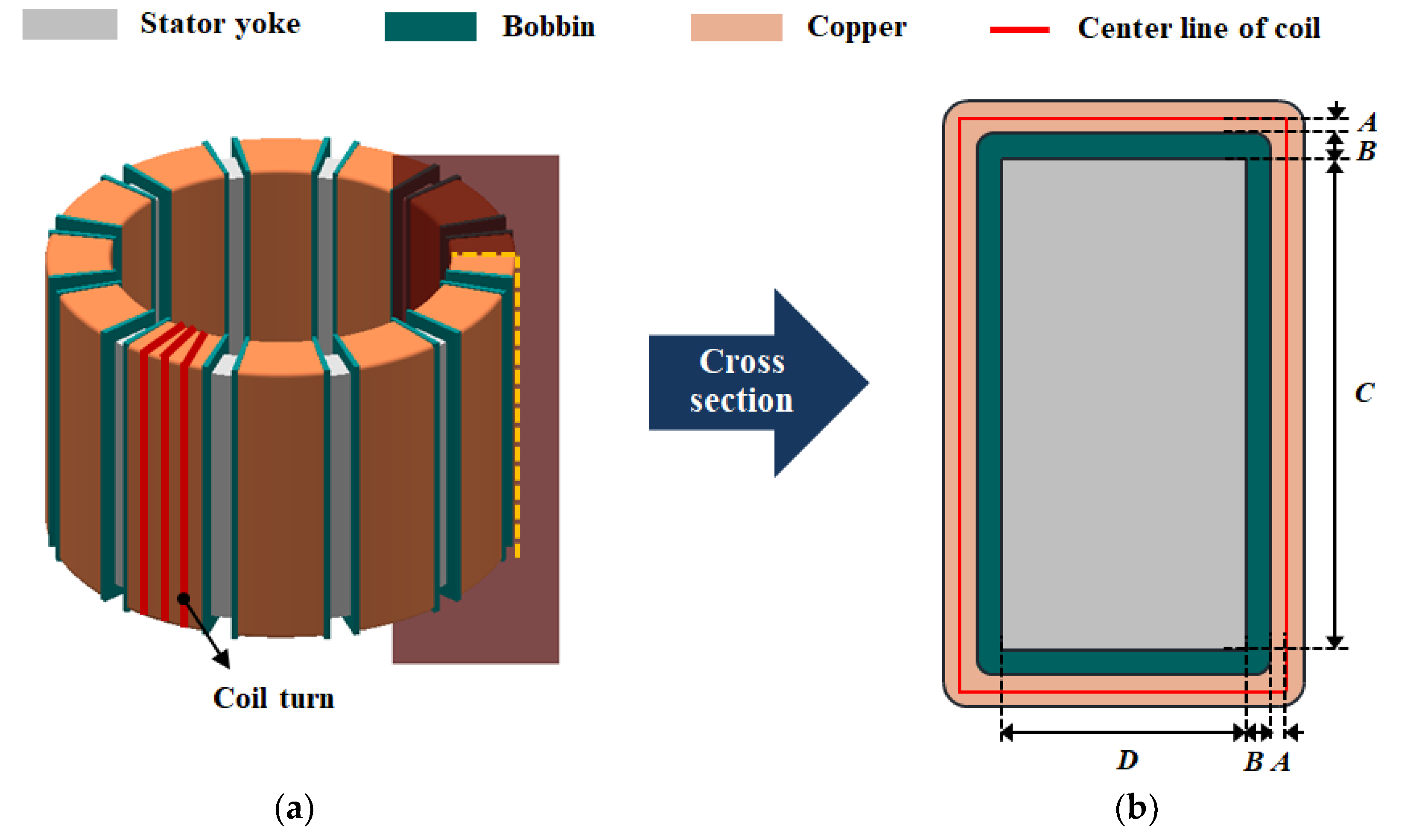
4.1.4. Resistance
Finally, we described a method for calculating the resistance of the toroidal coil. As shown in
Figure 9a, it was assumed that each turn of the armature coils were all wound with the same length. Moreover, as shown in
Figure 9b, in the cross-sectional view of one turn of the coil, the coil length was assumed to be the length of the center line of the coil. In this case, the length of one turn of the coil is expressed as Equation (18), and the total coil length per phase can be calculated, as shown in Equation (19), by multiplying the length of one turn by the number of series turns per phase. Consequently, the phase resistance can be expressed by Equation (20).
where
is the radius of the coil,
is the thickness of the bobbin,
is the axial length of the yoke,
is the thickness of the yoke,
is the number of series turns per phase,
is the number of parallel circuits,
is the conductivity of copper and
is the cross-sectional area of the coil.
4.2. Verification Using FEA
To exclude the effect of leakage flux that varies depending on the shape of the permanent magnet and the air-gap length, the leakage coefficient in the equation was assumed to be 1. In the case of the FEA, the relative permeability of the core was assumed to be infinite for comparison with the analytical result. The winding angle and the number of coil turns of the verification models were changed as shown in
Table 2 and
Table 3, respectively. The coil is modeled in a rectangular shape for the convenience of modeling. The air-gap flux density, winding factor, and back EMF of the verification models were calculated using the previous equations, and were compared with the FEA results.
4.2.1. Winding Angle Variation
As shown in
Figure 10, when the number of coil turns is constant, the trends in the winding factor and back EMF according to the change in the winding angle were examined.
As shown in Equation (21), the winding factor was calculated as the ratio of the vector sum and the scalar sum of magnetic fluxes interlinked in one phase in the analysis result.
where,
is the sum of the flux linkages of each coil in the FEA result, and
is the value multiplied by the number of turns to the flux linkage in a single coil located at the center of the winding in the FEA result.
As shown in
Figure 11, in the case of M3, a phase difference occurs in the coil angle of the electric angle between each flux linkage. The total flux linkage graph of the A-phase coil in
Figure 11 is similar to the waveform of the flux linkage graph in
Figure 5.
As shown in
Figure 12, the air-gap magnetic flux density and winding factor according to the change in the winding angle are almost the same, within a 2% error. The calculated back EMF was approximately 9.3% higher due to the leakage flux between the permanent magnets generated in the FEA.
Consequently, as shown in
Figure 11, there is a phase difference between the flux linkages in the TSLM, unlike in the CM in which the winding factor is constant regardless of the number of turns. By contrast, in the TSLM, the winding factor changes if the winding angle is changed. Therefore, the back EMF in the slotless motor correlates not only with the number of turns but also with the winding angle.
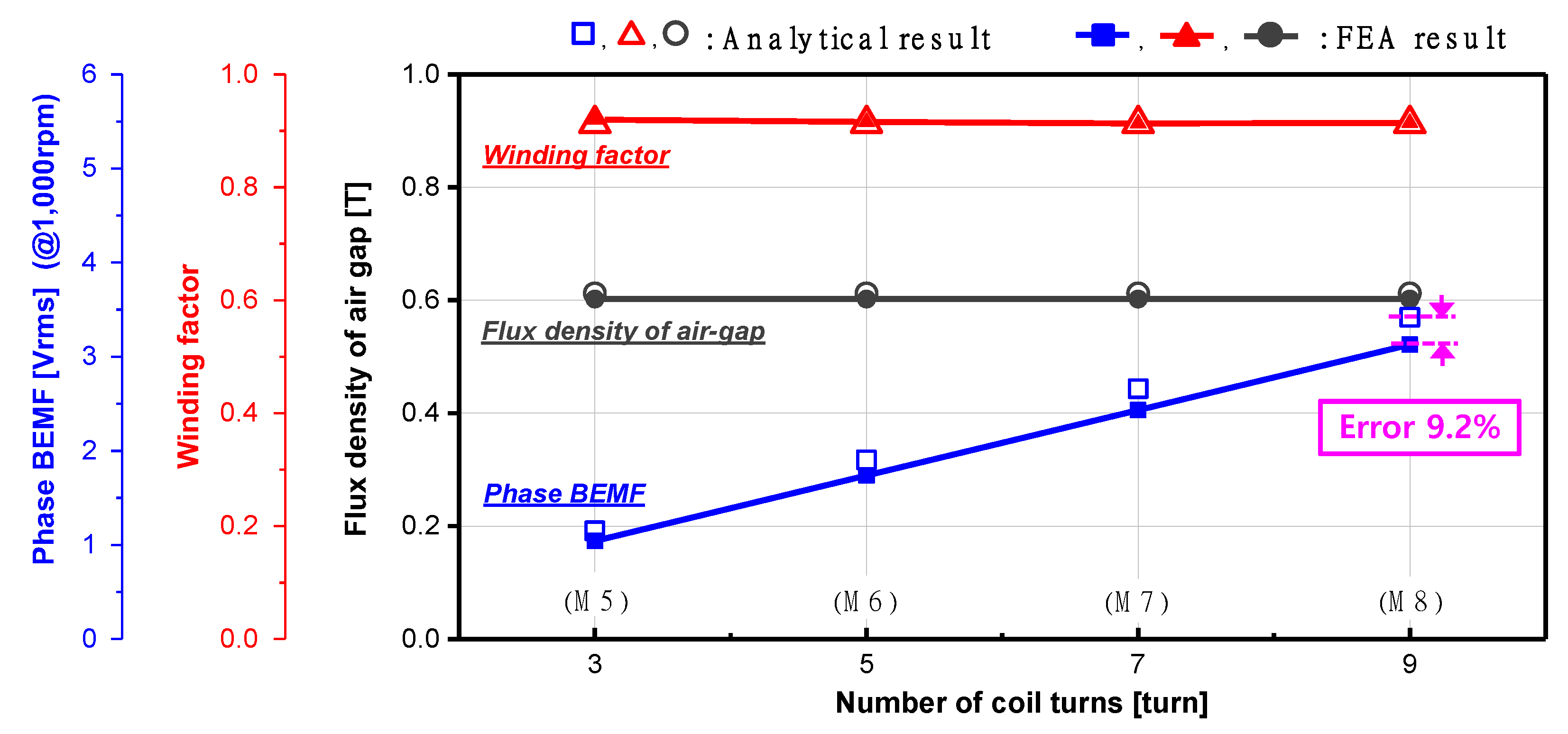
4.2.2. Number of Coil Turns Variation
As shown in
Figure 13 and
Table 3, when the winding angle is constant, the trends of the winding factor and back EMF based on the change in the number of coil turns were examined. In the vector diagram of
Figure 8b, the magnitude of the flux linkage of one coil was calculated using a trigonometric function. If the winding angle is fixed, and the number of coil turns is increased, the vector diagram will be similar to the shape of an arc. Therefore, the winding factor can be expressed briefly by Equation (22).
In the case of a model with a small number of turns, this formula may have a slightly lower accuracy than Equation (17). However, regardless of the number of turns or the coil angle, the winding factor of the TSLM can be calculated only with the winding angle. In
Figure 14, the air-gap magnetic flux density, winding factor, and back EMF according to the change in the number of turns were compared with the FEA results. Because the shape of the yoke and the permanent magnet in the verification models are the same, the air-gap magnetic flux density is also the same, and the error in the FEA results is within 2%. Although the winding factor was calculated using the simplified Equation (22), accurate results were obtained within 1% of the error from the FEA results. The calculated back EMF was approximately 9.2% higher due to the leakage flux between the permanent magnets generated in the FEA. As such, when the winding angle is constant, it can be deduced that the slotless motor has a constant winding factor regardless of the number of turns.
5. Prototype
Considering manufacturability among the reviewed models, M3 was finally produced as a prototype. For the structural assembly of the stator, the bobbin, and the housing cover, a stepped protrusion was modeled on the yoke. The resistance, back EMF, and cogging torque of the prototype were measured and compared with the FEA analytical results. In addition, the motor’s performance factors such as speed, current, output power, and efficiency according to the load torque were measured using a dynamometer and compared with the FEA results.
5.1. Shape and Specification
The shape of the finally manufactured model is shown in
Figure 15a. There are stepped one-layer and 2-layer protrusions on the outer surface of the stator yoke. The one-layer projection is for guiding the bobbin position, and the two-layer projection is for fixing the stator yoke. In
Figure 15b, the protrusion and the bobbin edge were made at minimum angles of 3.0 degrees and 1.5 degrees, respectively, for the convenience of production. Accordingly, the angle at which the coil is wound in the bobbin is 21 degrees.
Figure 15b also shows that the space in which the coil is arranged is narrower on the inside than on the outside. Based on the space inside the bobbin, the coil diameter and the number of turns of the final model were determined so that the coil could be fully occupied without any space. As a result, the final model selected was M3 with a winding angle of 21 degrees and seven coil turns. The rest of the design specifications are shown in
Table 4.
As shown in
Figure 16, a 2D electromagnetic field simulation was conducted for the final model using the Simcenter MAGNET of the Siemens software.
Figure 16a,b show the no-load magnetic flux density and mesh distribution, respectively.
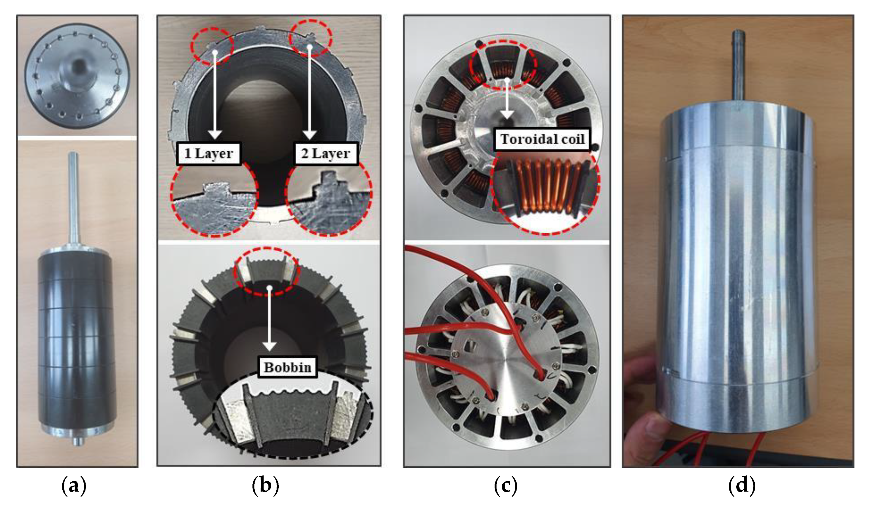
5.2. Manufacturing
As shown in
Figure 17, the prototype was manufactured. The permanent magnet has a ring-type shape and is magnetized with eight poles in the radial direction. In
Figure 17a, the rotor consists of a six-segment ring-type permanent magnet, a balancing core, and a shaft. The stator yoke with the protrusion was manufactured as shown in
Figure 17b, and the bobbin was inserted into the upper and lower parts of the stator yoke.
For the purpose of guiding the coil position, a semicircular hole was modeled on the outer surface of the bobbin, and the angle between the semicircular holes was 3 degrees. In
Figure 17c, the final in and out coils from each coil bunch after being wound on the coil are connected inside the cover of the case.
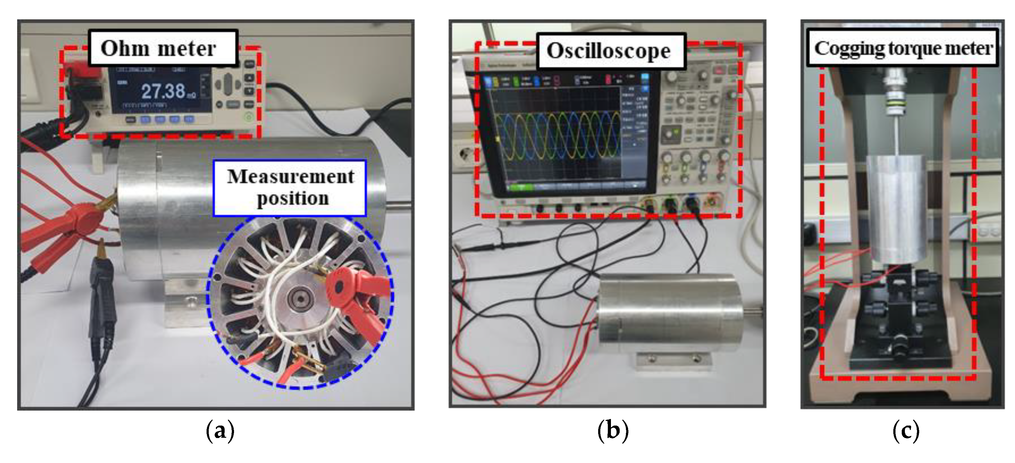
5.3. Testing
In the prototype, the resistance, back EMF, and cogging torque were measured and compared with the analytical FEA results.
First, as shown in
Figure 18a, the phase resistance was measured at the neutral point and the A-phase terminal before the lead wire. The resistance was calculated using Equation (20) and was approximately 10% lower than the measured value. In the prototype, there is inevitably a gap between the bobbin and the coil in the process of winding the coil, and the connection between each phase must be made. For this reason, the coil length of the prototype is inevitably longer than the calculated value, while the measured resistance is also higher.
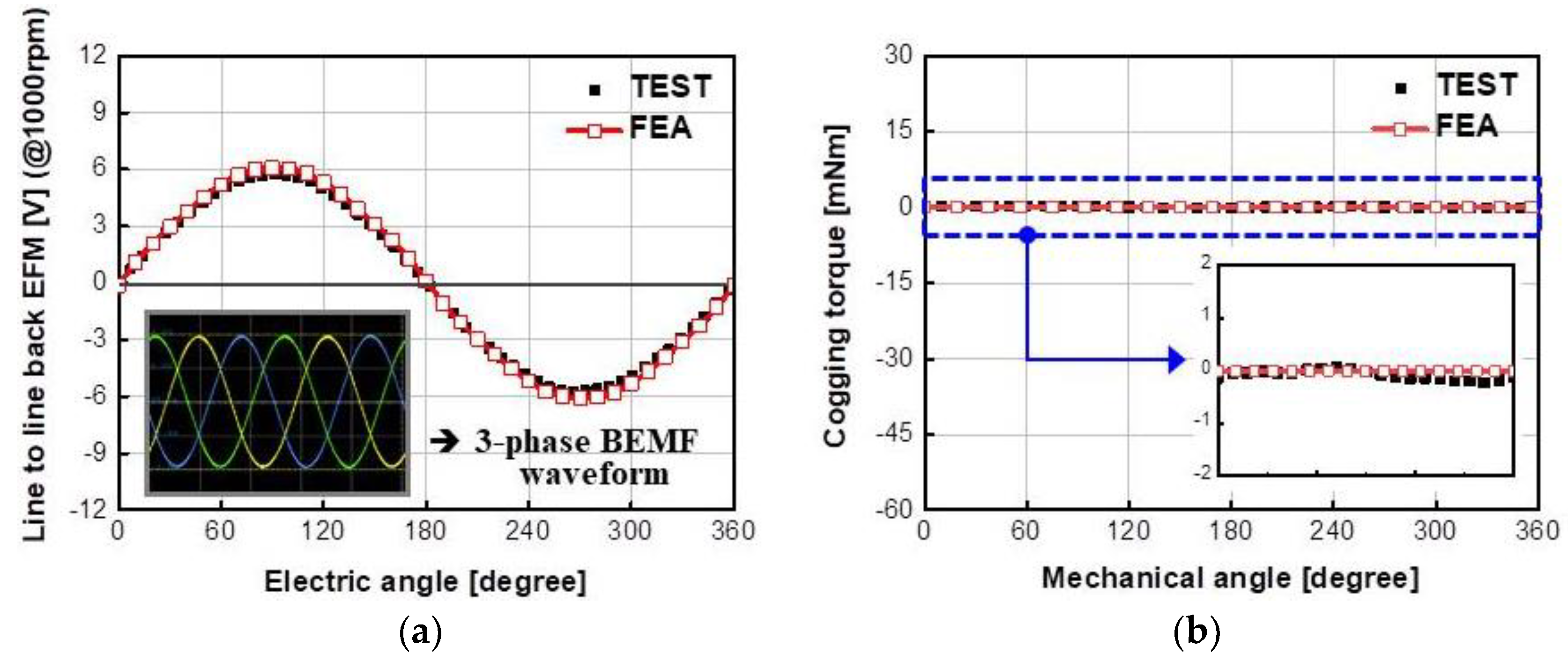
Further, the line-to-line back EMF was measured as shown in
Figure 18b. The prototype was driven at 1000 rpm by an external drive system. In
Figure 19a, the three-phase back EMF waveform was measured as a symmetrical sinusoidal waveform.
Table 5 shows that the measured line-to-line back EMF was approximately 7.5% lower than the FEA result. This was considered to be caused by the permanent magnet’s magnetization and manufacturing tolerances.
Furthermore, the cogging torque was measured as shown in
Figure 18c. A torque meter (ATM-50MN) was used as the measuring equipment, and the cogging torque was measured at 0.1 degree intervals. The TSLM has a zero-cogging torque in theory. Similarly, in
Figure 19b, the FEA result shows that the cogging torque is almost zero. However, the actual experimental result was 0.6 mNm peak-to-peak. Additional cogging torque may occur due to manufacturing reasons such as when the permanent magnet is not evenly magnetized, or the rotor shaft is not aligned. In the case of the CM designed to reduce cogging torques, the cogging torque occurs at approximately 30 mNm [
26,
27,
28]. Compared with the CM, the cogging torque of the prototype is very small, which is negligible.
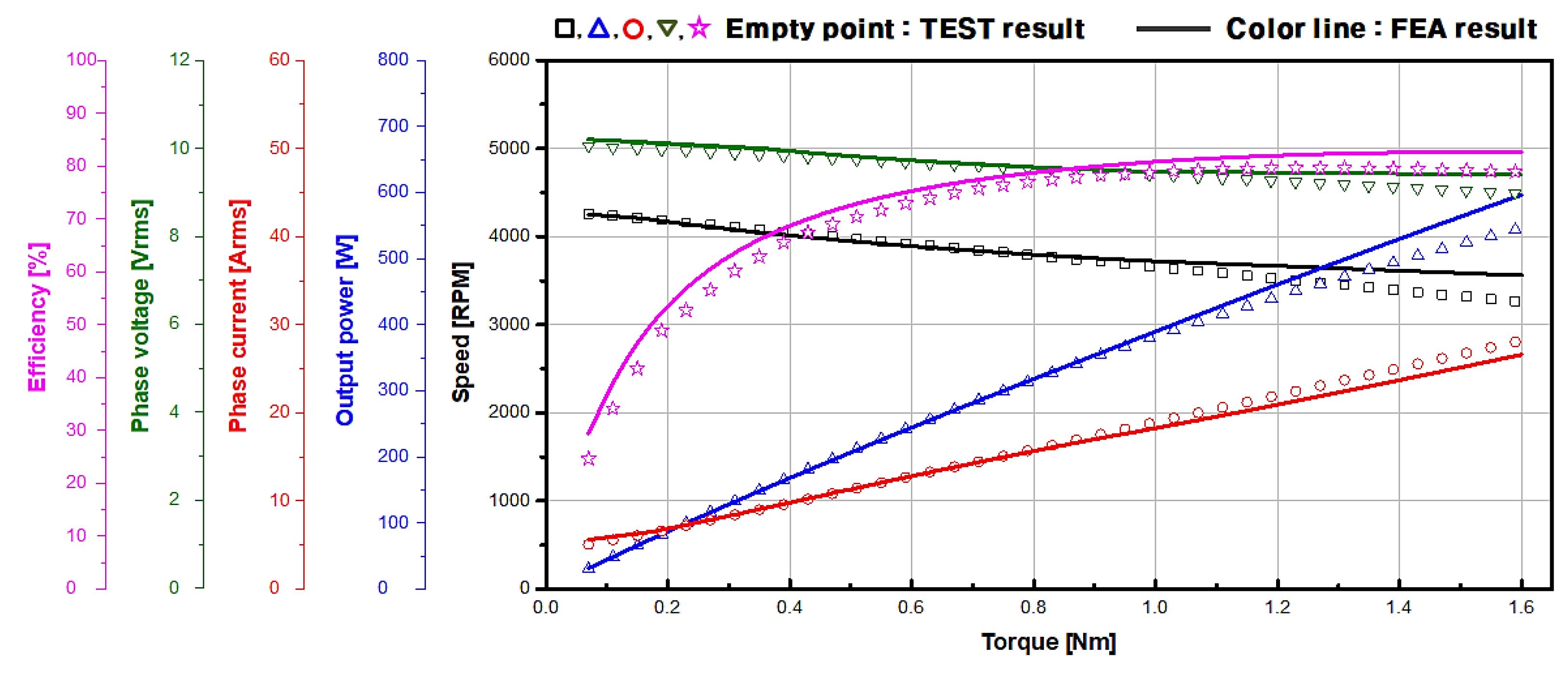
Finally, as shown in
Figure 20, performance factors of the prototype such as speed, output, and efficiency according to the load torque were measured. A sensorless BLDC drive was used as the controller, and a power analyzer, oscilloscope, and dynamo torque meter were used as measuring equipment.
Figure 21 shows the result of the measurements, and the performance of the prototype measured had a similar trend to the FEA result. However, the phase voltage was approximately 5% lower than the FEA result due to the voltage drop in the coil, which was caused by the increase in temperature in the high-torque, low-speed region. Because of the reduced phase voltage in the high-torque, low-speed region, the speed was reduced, and eventually the output power decreased by approximately 8%. The maximum efficiency of the prototype was measured to be approximately 80%. Because the prototype was designed for ease of fabrication rather than performance, the magnetic air-gap length is quite long. If optimal design of the coil diameter, number of turns, and air-gap length are achieved, the efficiency will be improved more than that of the prototype presented in this study.
6. Conclusions
Toroidal coils are already widely used in transformers, but very rarely used in permanent magnet synchronous motors. Therefore, in this study, a slotless motor with toroidal winding was introduced, and the basic motor characteristics were explained.
First, the proposed slotless motor generates a rotating magnetic field by the armature coil base on the same principle as a general motor. In addition, the back EMF has a sinusoidal waveform at intervals of 120 degrees.
Next, the proposed slotless motor was equivalent to a lumped-parameter circuit. The basic motor parameters such as air-gap flux density, flux linkage, winding factor, and back EMF were calculated and compared with the FEA results. The air-gap flux density and winding factor were almost the same, with an error of less than 1%, and the back EMF had an error of approximately 10% from the result of the analysis due to the leakage flux between the permanent magnets. Unlike general motors, in slotless motors, the change in winding angle or coil angle affects the winding factor, and consequently the back EMF also changes.
Finally, the resistance, back EMF and cogging torque of the prototype were measured. In addition, the motor’s performance parameters such as speed, output, and efficiency were measured through the dynamo load test. In this case, the phase voltage of the measured value was about 5% lower than that of the FEA result due to the voltage drop generated by the motor and controller in the high-torque region. As a result, the output power decreased by approximately 8% compared with the FEA result.
This paper was written to introduce the basic characteristics of a slotless motor to which a toroidal coil structure is applied. Therefore, the prototype was designed with an emphasis on manufacturing convenience rather than performance, and an optimal design for performance improvement was not made. If the optimal design of the coil diameter, number of turns, and air-gap length are achieved, the efficiency is expected to be higher than that of the prototype presented in this study.
We believe that this article can be a basic indicator for the design and convenient manufacturing of slotless motors to which toroidal winding is applied.
Author Contributions
Methodology, H.-Y.L.; investigation, H.-Y.L., J.-Y.S., S.-Y.Y. and S.-H.P.; validation, H.-Y.L. and S.-H.P.; visualization, J.-Y.S. and S.-Y.Y.; supervision, S.-O.K. and M.-S.L.; writing—review and editing, H.-Y.L., J.-Y.S., S.-O.K., S.-H.P. and M.-S.L. All authors have read and agreed to the published version of the manuscript.
Funding
This study has been conducted with the support of the Korea Institute of Industrial Technology as “Development of Core Technologies for a Working Partner Robot in the Manufacturing Field” (KITECH EO-21-0004).
Institutional Review Board Statement
Not applicable.
Informed Consent Statement
Not applicable.
Data Availability Statement
Not applicable.
Acknowledgments
Special thanks to MK E&S and IL Shin Motor Ltd.
Conflicts of Interest
The authors declare no conflict of interest.
References
- Yu, H.-C.; Yu, B.-S.; Yu, J.-T.; Lin, C.-K. A dual notched design of radial-flux permanent magnet motors with low cogging torque and rare earth material. IEEE Trans. Magn. 2014, 50, 1–4. [Google Scholar] [CrossRef]
- Ocak, O.; Aydin, M. An innovative semi-FEA based, variable magnet-step-skew to minimize cogging torque and torque pul-sations in permanent magnet synchronous motors. IEEE Access 2020, 8, 210775–210783. [Google Scholar] [CrossRef]
- Liu, T.; Huang, S.; Gao, J.; Lu, K. Cogging torque reduction by slot-opening shift for permanent magnet machines. IEEE Trans. Magn. 2013, 49, 4028–4031. [Google Scholar] [CrossRef]
- Zhou, Y.; Li, H.; Meng, G.; Zhou, S.; Cao, Q. Analytical calculation of magnetic field and cogging torque in surface-mounted permanent magnet machines accounting for any eccentric rotor shape. IEEE Trans. Ind. Electron. 2014, 62, 1. [Google Scholar] [CrossRef]
- Rao, J.; Gao, Y.; Li, D.; Qu, R. Performance analysis of interior permanent magnet motor using overlapping windings with fractional ratio of slot to pole pair. IEEE Trans. Appl. Supercond. 2016, 26, 1–5. [Google Scholar] [CrossRef]
- Yokoi, Y.; Higuchi, T. Stator design of alternate slot winding for reducing torque pulsation with magnet designs in sur-face-mounted permanent magnet motor. IEEE Trans. Magn. 2015, 51, 8202911. [Google Scholar] [CrossRef] [Green Version]
- Mynarek, P.; Kołodziej, J.; Młot, A.; Kowol, M.; Łukaniszyn, M. Influence of a winding short-circuit fault on demagnetization risk and local magnetic forces in V-shaped interior PMSM with distributed and concentrated winding. Energies 2021, 14, 5125. [Google Scholar] [CrossRef]
- Liu, F.; Li, H.; Liu, L.; Zou, R.; Liu, K. A control method for IPMSM based on active disturbance rejection control and model predictive control. Mathematics 2021, 9, 760. [Google Scholar] [CrossRef]
- Kao, W.-T.; Hwang, J.-C.; Liu, J.-E. Development of three-phase permanent-magnet synchronous motor drive with strategy to suppress harmonic current. Energies 2021, 14, 1583. [Google Scholar] [CrossRef]
- Sun, G.; Yang, G.; Wang, Y.; Su, J. Unified fault-tolerant control strategy with torque ripple compensation for five-phase permanent magnet synchronous motor based on normal decoupling. Energies 2019, 12, 1127. [Google Scholar] [CrossRef] [Green Version]
- Ortega, A.J.P.; Paul, S.; Islam, R.; Xu, L. Analytical model for predicting effects of manufacturing variations on cogging torque in surface-mounted permanent magnet motors. IEEE Trans. Ind. Appl. 2016, 52, 3050–3061. [Google Scholar] [CrossRef]
- Kim, J.; Yoon, M.; Hong, J.; Kim, S. Analysis of cogging torque caused by manufacturing tolerances of surface-mounted permanent magnet synchronous motor for electric power steering. IET Electr. Power Appl. 2016, 10, 691–696. [Google Scholar] [CrossRef]
- Khan, M.A.; Husain, I.; Islam, M.R.; Klass, J.T. Design of experiments to address manufacturing tolerances and process vari-ations influencing cogging torque and back EMF in the mass production of the permanent-magnet synchronous motors. IEEE Trans. Ind. Appl. 2014, 50, 346–355. [Google Scholar] [CrossRef]
- Jeong, C.; Lee, D.; Hur, J. Mitigation method of slot harmonic cogging torque considering unevenly magnetized permanent magnets in PMSM. Energies 2019, 12, 3887. [Google Scholar] [CrossRef] [Green Version]
- Dorrell, D.G.; Popescu, M. Odd stator slot numbers in brushless DC machines—An aid to cogging torque reduction. IEEE Trans. Magn. 2011, 47, 3012–3015. [Google Scholar] [CrossRef]
- Sung, S.J.; Park, S.J.; Jang, G.H. Cogging torque of brushless DC motors due to the interaction between the uneven magnetization of a permanent magnet and teeth curvature. IEEE Trans. Magn. 2011, 47, 1923–1928. [Google Scholar] [CrossRef]
- Lesniewska, E. Influence of the selection of the core shape and winding arrangement on the accuracy of current transformers with through-going primary cable. Energies 2021, 14, 1932. [Google Scholar] [CrossRef]
- Platero, C.A.; Sánchez-Fernández, J.Á.; Gyftakis, K.N.; Blázquez, F.; Granizo, R. Performance problems of non-toroidal shaped current transformers. Sensors 2020, 20, 3025. [Google Scholar] [CrossRef]
- Zhang, H.; Wang, S.; Yuan, D.; Tao, X. Double-ladder circuit model of transformer winding for frequency response analysis considering frequency-dependent losses. IEEE Trans. Magn. 2015, 51, 1–4. [Google Scholar] [CrossRef]
- Bu, F.; Yang, Z.; Gao, Y.; Pan, Z.; Pu, T.; Degano, M.; Gerada, C. Speed ripple reduction of direct-drive PMSM servo system at low-speed operation using virtual cogging torque control method. IEEE Trans. Ind. Electron. 2021, 68, 160–174. [Google Scholar] [CrossRef]
- Xia, C.; Ji, B.; Yan, Y. Smooth speed control for low-speed high-torque permanent magnet synchronous motor using propor-tional-integral-resonant controller. IEEE Trans. Ind. Electron. 2015, 62, 2123–2134. [Google Scholar] [CrossRef]
- Burnand, G.; Thabuis, A.; Araujo, D.M.; Perriard, Y. Novel optimized shape and topology for slotless windings in BLDC machines. IEEE Trans. Ind. Appl. 2019, 56, 1275–1283. [Google Scholar] [CrossRef]
- Dehez, B.; Baudart, F.; Markovic, M.; Perriard, Y. Theoretical and experimental investigation of Flex-PCB air-gap windings in slotless BLDC machines. IEEE Trans. Ind. Appl. 2014, 50, 3153–3160. [Google Scholar] [CrossRef]
- Seo, J.-M.; Kim, J.-H.; Jung, I.-S.; Jung, H.-K. Design and analysis of slotless brushless DC motor. IEEE Trans. Ind. Appl. 2010, 47, 730–735. [Google Scholar] [CrossRef]
- Hanselman, D. Brushless Permanent Magnet Motor Design, 2nd ed.; The Writer’s Collective: Cranston, RI, USA, 2003; pp. 67–72. [Google Scholar]
- Choi, J.-Y.; Park, Y.-S.; Jang, S.-M. Experimental verification and electromagnetic analysis for performance of interior PM motor according to slot/pole number combination. IEEE Trans. Magn. 2012, 48, 987–990. [Google Scholar] [CrossRef]
- Ou, J.; Liu, Y.; Qu, R.; Doppelbauer, M. Experimental and theoretical research on cogging torque of PM synchronous motors considering manufacturing tolerances. IEEE Trans. Ind. Electron. 2018, 65, 3772–3783. [Google Scholar] [CrossRef]
- Sempere, V.S.; Payán, M.B.; Bueno, J.R.C.; Bueno, R.C. Cogging torque measurement using the electromotive force in surface-mounted permanent-magnet motors. IEEE Trans. Magn. 2015, 51, 1. [Google Scholar] [CrossRef]
Figure 1.
Motor structure: (a) Conventional motor, and (b) Slotless motor with toroidal winding.
Figure 1.
Motor structure: (a) Conventional motor, and (b) Slotless motor with toroidal winding.
Figure 2.
Direction of flux linkage: (a) Conventional motor, and (b) Slotless motor with toroidal winding.
Figure 2.
Direction of flux linkage: (a) Conventional motor, and (b) Slotless motor with toroidal winding.
Figure 3.
Three-phase BLDC six-step inverter circuit and the TSLM.
Figure 3.
Three-phase BLDC six-step inverter circuit and the TSLM.
Figure 4.
Driving process of three-phase 2-pole 3-coil bunch TSLM: (a) Sequence I, (b) Sequence II, (c) Sequence III, (d) Sequence IV, (e) Sequence V, and (f) Sequence VI.
Figure 4.
Driving process of three-phase 2-pole 3-coil bunch TSLM: (a) Sequence I, (b) Sequence II, (c) Sequence III, (d) Sequence IV, (e) Sequence V, and (f) Sequence VI.
Figure 5.
Flux-linkage waveform of A-phase coil by permanent magnet.
Figure 5.
Flux-linkage waveform of A-phase coil by permanent magnet.
Figure 6.
Fundamental model and magnetic circuit: (a) Fundamental motor structure, (b) Magnetic circuit model, and (c) Simplified magnetic circuit.
Figure 6.
Fundamental model and magnetic circuit: (a) Fundamental motor structure, (b) Magnetic circuit model, and (c) Simplified magnetic circuit.
Figure 7.
Air-gap flux density distribution and its fundamental component.
Figure 7.
Air-gap flux density distribution and its fundamental component.
Figure 8.
Winding factor of the TSLM: (a) Coil structure; (b) Coil vector diagram.
Figure 8.
Winding factor of the TSLM: (a) Coil structure; (b) Coil vector diagram.
Figure 9.
Structural diagram of the toroidal coil for resistance calculation: (a) 3D Armature coil, and (b) Cross-section of toroidal coil.
Figure 9.
Structural diagram of the toroidal coil for resistance calculation: (a) 3D Armature coil, and (b) Cross-section of toroidal coil.
Figure 10.
Coil shape according to winding angle.
Figure 10.
Coil shape according to winding angle.
Figure 11.
Total flux linkage and each flux-linkage waveform of M3.
Figure 11.
Total flux linkage and each flux-linkage waveform of M3.
Figure 12.
Back EMF trend according to the variation in the winding angle.
Figure 12.
Back EMF trend according to the variation in the winding angle.
Figure 13.
Coil shape according to number of coil turns.
Figure 13.
Coil shape according to number of coil turns.
Figure 14.
Back EMF trend according to the variation in the number of coil turns.
Figure 14.
Back EMF trend according to the variation in the number of coil turns.
Figure 15.
Structure of the prototype model: (a) 2D model, and (b) Angle of yoke protrusion and bobbin.
Figure 15.
Structure of the prototype model: (a) 2D model, and (b) Angle of yoke protrusion and bobbin.
Figure 16.
FEA 2D Model of the prototype: (a) Flux density distribution, and (b) Mesh.
Figure 16.
FEA 2D Model of the prototype: (a) Flux density distribution, and (b) Mesh.
Figure 17.
Prototype components: (a) Rotor, (b) Stator yoke and bobbin, (c) Bottom view, and (d) Side view.
Figure 17.
Prototype components: (a) Rotor, (b) Stator yoke and bobbin, (c) Bottom view, and (d) Side view.
Figure 18.
Testing: (a) Resistance, (b) back EMF, and (c) Cogging torque.
Figure 18.
Testing: (a) Resistance, (b) back EMF, and (c) Cogging torque.
Figure 19.
Testing result: (a) back EMF, and (b) Cogging torque.
Figure 19.
Testing result: (a) back EMF, and (b) Cogging torque.
Figure 20.
Measurement equipment of the dynamo load test.
Figure 20.
Measurement equipment of the dynamo load test.
Figure 21.
Result of the dynamo load test.
Figure 21.
Result of the dynamo load test.
Table 1.
Operation sequences of six step.
Table 1.
Operation sequences of six step.
| Operation Mode | I | II | III | IV | V | VI |
|---|
| Operation element | T1 | T1 | T3 | T3 | T5 | T5 |
| T6 | T2 | T2 | T4 | T4 | T6 |
Table 2.
Coil specification according to winding variation.
Table 2.
Coil specification according to winding variation.
| Model | Winding Angle
(Deg.) | Number of Coil Turns
(Turn) |
|---|
| M1 | 14.0 | 7 |
| M2 | 17.5 | 7 |
| M3 | 21.0 | 7 |
| M4 | 24.5 | 7 |
Table 3.
Coil specification according to number of coil turns.
Table 3.
Coil specification according to number of coil turns.
| Model | Winding Angle
(Deg.) | Number of Coil Turns
(Turn) |
|---|
| M5 | 21.0 | 3 |
| M6 | 21.0 | 5 |
| M7 | 21.0 | 7 |
| M8 | 21.0 | 9 |
Table 4.
Prototype specification.
Table 4.
Prototype specification.
| Item | Unit | Value |
|---|
| Motor type | - | Slotless |
| Number of Poles | - | 8 |
| Number of Coil bunch | - | 12 |
| Yoke outer diameter | mm | 80.0 |
| Magnet outer diameter | mm | 59.0 |
| Stack length | mm | 120.0 |
| Number of coil turns | turn | 7 |
| Coil diameter | mm | 1.3 |
| Magnetic air-gap length | mm | 3.2 |
| Number of parallel circuits | - | 2 |
| PM material | - | Sintered NdFeB |
| Core material | - | 50PN470 |
| DC link voltage | Vdc | 24 |
Table 5.
Comparison of analysis, FEA and measurement results.
Table 5.
Comparison of analysis, FEA and measurement results.
| Item | Unit | Value | Note |
|---|
| ANA | FEA | EXP |
|---|
| Phase resistance | mΩ | 24.6 | - | 27.4 | Room temperature
20 °C |
| Line-to-line back EMF | Vrms | 4.6 | 4.3 | 4.0 | Fundamental wave
1000 rpm |
| Cogging torque | mNm | - | 0.0 | 0.6 | Peak-to-peak |
| Publisher’s Note: MDPI stays neutral with regard to jurisdictional claims in published maps and institutional affiliations. |
© 2021 by the authors. Licensee MDPI, Basel, Switzerland. This article is an open access article distributed under the terms and conditions of the Creative Commons Attribution (CC BY) license (https://creativecommons.org/licenses/by/4.0/).


 ,
, 


