Experimental and Numerical Simulation Study on Co-Incineration of Solid and Liquid Wastes for Green Production of Pesticides

College of Electromechanical Engineering, Qingdao University of Science and Technology, Qingdao 266061, China
*
Author to whom correspondence should be addressed.
Processes 2019, 7(10), 649; https://doi.org/10.3390/pr7100649
Submission received: 16 August 2019
/
Revised: 12 September 2019
/
Accepted: 17 September 2019
/
Published: 23 September 2019
(This article belongs to the Special Issue Green Technologies for Production Processes)
Abstract
:A large amount of solid and liquid waste is produced in pesticide production. It is necessary to adopt appropriate disposal processes to reduce pollutant emissions. A co-incineration scheme for mixing multi-component wastes in a rotary kiln was proposed for waste disposal from pesticide production. According to the daily output of solid and liquid wastes, the proportion of mixing was determined. An experiment of the co-incineration of solid and liquid wastes was established. Experimental results showed that the mixed waste could be completely disposed at 850 °C, and the residence time in the kiln exceeded 1 h. A model method for mixture and diesel oil-assisted combustion was proposed. Numerical simulation was performed to predict the granular motion and reveal the combustion interactions of the co-incineration of mixed wastes in the rotary kiln. Simulation results reproduced movements, such as rolling and cascading, and obtained the optimum rotational speed and diesel oil flow for the rotary kiln incineration operation. The simulation showed that the temperature in the kiln was maintained at 850 °C, and the mass fraction of CO and O2 at the outlet reached the standard for the complete combustion of the waste. Finally, the rotary kiln incineration and flue gas treatment processes were successfully applied in engineering for green production of pesticides.
1. Introduction
China is not only a major country in the use of pesticides, it is also a producer [1], with a total production of 2.491 million tons of pesticide in 2017. However, an unintended consequence is that this pesticide production also produces considerable multi-component wastes such as liquid and solid wastes. Liquid and solid wastes generated during pesticide production are hazardous wastes [2]. Solid wastes produced by pesticides are the residual sludge of biochemical systems, semi-solid pentylamine and aniline, viscous kettle residue, waste packaging materials and activated carbon. Meanwhile, pesticide liquid wastes have a high chemical oxygen demand, high salt content and high toxicity [3]. Their characteristics of complex sources, wide variety and difficult degradability of waste lead to great difficulty in hazardous waste disposal. If disposed improperly, these hazardous wastes are harmful to the environment. Therefore, the disposal of liquid and solid wastes in pesticide production is still a difficulty and hot spot of waste disposal at present.
Common disposed methods include landfilling, physical disposed processes, biological conversion technologies, and incineration. Landfills contain pollutants that can also cause groundwater pollution [4]. Physical processing can only simplify the separation of different components of hazardous wastes [5]. Bioconversion technology can only convert biodegradable waste into high quality products, a process which has limitations [6]. It has been reported that incineration is an advanced choice in comparison with other disposed methods. The main purpose of incineration is to disposal of hazardous wastes while minimizing environmental impact and recovering energy. Incineration is an effective means of realizing harmlessness, reduction and resource utilization [7,8,9].
On the marketisation level, the high-temperature incineration method for solid wastes is the main disposal method [10,11]. However, the incineration of liquid wastes in combustion plants is not common, and only a few cases have been reported. In liquid waste combustion, inorganic salts in waste liquor will melt at a high temperature, which will aggravate the denudation of refractories and the slagging of ash on the wall. The acid gas produced by incineration not only pollutes the atmosphere but also reduces the dew point of flue gas, which causes corrosion and ash accumulation in the furnace. When the viscosity of liquid wastes is high or contains some impurities, the liquid wastes need to be filtered to remove such impurities. Hence, waste liquid incineration has the problems of high cost and low profit [12,13].
In recent years, the disposal method of co-incineration of hazardous waste has been paid increasing attention. The co-incineration of solid wastes and sewage has been intensively applied in many countries. Wang [14] assessed the environmental impacts of the sewage treatment scheme. Their results showed that the co-incineration of sewage and municipal solid waste is beneficial to reduce greenhouse gas emissions. Hu [15] analyzed the combustion characteristics of municipal solid waste, paper mill sludge and their mixture. When the mixing ratio of sludge was less than 30%, there was a significant synergistic effect in co-incineration. Lin [16] simulated the conditions of the co-incineration of municipal solid waste and sewage in an incinerator. The simulation results showed that the hybrid fuel could be completely burned to meet pollutant emission standards. The co-incineration of solid wastes and sewage has been widely used; however, that of solid and liquid wastes has rarely been reported, although it has a good application prospect in the waste disposal of pesticide production.
In comparison with other waste incineration equipment, the advantages of hazardous waste processing in rotary kilns include long residence time, high burning temperature, stable burning state, neutralization of acid waste gas and low cost [17,18,19,20]. Rotary kiln incinerators are widely used in many large factories as a safe method to disposal of hazardous waste. They are a general furnace for the disposal of solid, liquid, gaseous and complex combustible wastes [20,21]. Bujak [22] treated medical waste through rotary kiln incineration and analyzed environmental, economic and energy aspects. The results showed that the rotary kiln disposal produces significant environmental and economic benefits. Bujak [23] also introduced the preliminary results of the use of rotary kilns in plastic waste incineration. The actual atmospheric emission from the heat treatment of plastic waste is lower than the current emission standards. Mellmann [24] predicted the different forms of transverse bed motion in a rotary cylinder to understand particle behavior for efficient industrial production. The theory and technology for treating waste in rotary kilns has matured; however, the co-incineration of mixed multi-component wastes using rotary kilns has rarely been reported.
In the present work, a co-incineration scheme for mixed multi-component wastes in a rotary kiln was proposed for waste disposal from pesticide production. Firstly, the proportion of mixing of solid and liquid wastes was determined, and the elemental composition, calorific value and ash melting point of the mixture were measured. The experiment of co-incineration of solid wastes and liquid wastes was established. The slag was collected at different incineration times, and the slag clinker ignition loss was measured. This study proposes a model method for mixture and diesel oil-assisted combustion, explores these particle motion characteristics, and reveals the combustion interactions of the co-incineration of mixed wastes. The results obtained could help to further understand waste co-incineration. Finally, the rotary kiln and the entire treatment system were reconstructed and commissioned. The co-incineration of multi-component wastes disposal technology in a rotary kiln could realize the harmless treatment of hazardous waste, a process which has better social, environmental, and economic benefits.
2. Materials and Methods
2.1. Material Characteristics
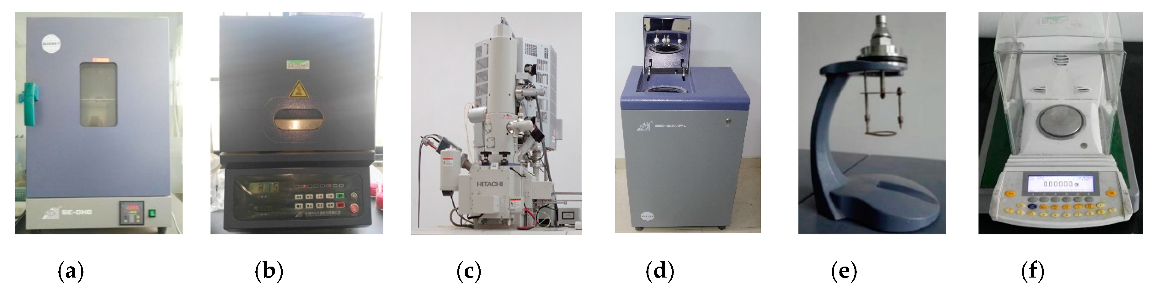
As shown in Figure 1, materials produced in pesticide production involve a complex composition (i.e., aniline, amyl amine, kettle residue, kettle substrate, floccus, pendimethalin, activated carbon, and mother liquor of methomyl). In material pretreatment, liquid and solid wastes were thoroughly mixed in a mass ratio of 4:1 and were fed into the kiln inlet through a screw feeder. A constant temperature oven, muffle furnace, scanning electron microscope, calorimeter, crucible holder and electronic balance were used to measure material characteristics. The experimental measurement equipment is shown in Figure 2.
According to Chinese Standards GB/T 212-2008, the moisture content of the mixed waste is 23.6%, and the ash content of the mixed waste is 20.4%. Moisture content was measured by heating the waste in a constant temperature oven at 105 °C, and the ash content was measured by igniting the mixed waste in a muffle furnace at 850 °C to a constant weight. The elements in the mixed waste were measured by a scanning electron microscope. The element composition is shown in Table 1.
The calorific value of waste is an important physical parameter for incineration. The calorific value of the mixed waste was determined using the oxygen bomb method. The standard benzoic acid is a combustion additive with a calorific value of 26,479 J/g. The waste was placed on a crucible and ignited with an ignition wire. The calorific value of the mixed waste was measured by a calorimeter. Solid wastes in total and wastes in total were calculated by weighted average. The daily production, mass fraction and calorific value of the material components are summarized in Table 2. Table 2 indicates that the daily production of liquid wastes was 4000 kg, which was the main part of waste disposal. The daily production of solid wastes in total was 1145 kg, which was only 22% of the total waste. The caloric value of total liquid wastes was low, whereas that of the total solid wastes was high. The calorific value of mixed wastes was 4050 kJ/kg, as determined by the weighted average method (Equations (1) and (2)). The calorific value was low, and diesel oil needs be added in auxiliary combustion.
The ash fusion temperature, which was measured by a pyramid method (GB/T 219-2008), maintained its original shape before 1400 °C and melted directly to the molten state at 1450 °C. Consequently, the material of the ash fusion temperature was higher than 1400 °C, and the temperature difference between deformation and softening temperatures was less than 100 °C. The normal working temperature range of the solid-state rotary kiln was 800–1000 °C. Thus, the temperature in the kiln was lower than the ash fusion temperature, and the ash was not easily melted to avoid slagging on the inner wall of the furnace.
2.2. Co-Incineration Experiment in the Rotary Kiln
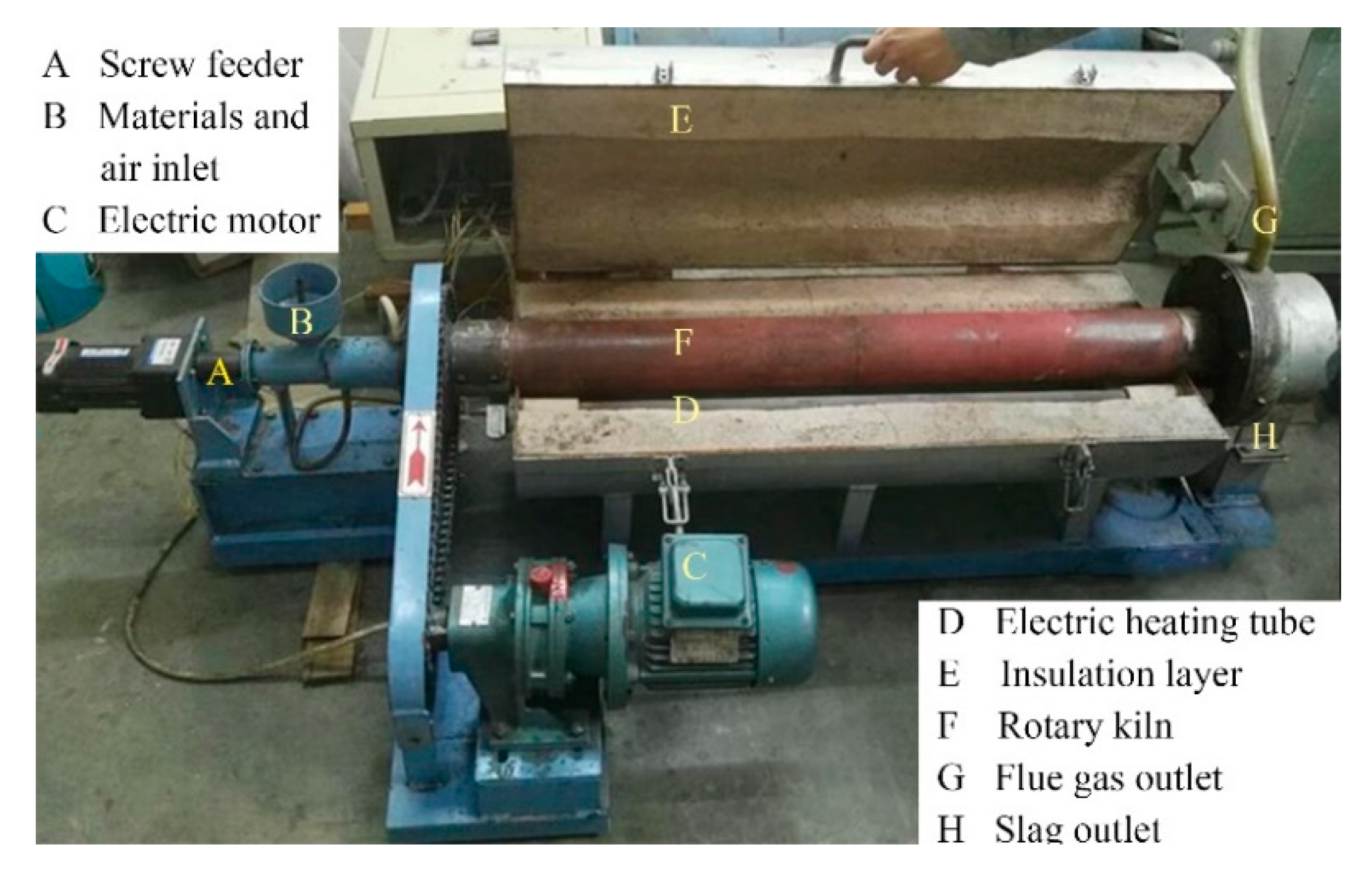
A co-incineration experimental system (Figure 3) was established to explore whether mixed wastes could be completely burned in a rotary kiln and to analyze the incineration process. The internal diameter and length of the rotary kiln were 150 and 1630 mm, respectively. The entrance of the screw feeding machine was also the air inlet. Cement pouring was used for the thermal insulation layer, and the kiln inclination angle range was 0–5°. The cylinder of the rotary kiln was driven by a motor, and the speed range was 0.5–5 r/min. A thermocouple that could monitor the central temperature of the furnace in real time was installed in the middle of the kiln. Moreover, the control box could automatically adjust the power of the electric heater by setting the furnace temperature to control the temperature in the kiln.
The constant temperature of the kiln was kept at 850 °C, and the materials from the total wastes were continuously fed by imports. Moreover, Table 2 indicates that the state of the wastes was semi-fluid. The feeding speed and time were 0.05 kg/min and 10 min, respectively, and the total feeding was 0.5 kg. In the experiment, the slag appeared after the mixed waste was sent to the kiln for 60 min. Thus, the slag was collected after 60, 70, 80, 90, 100 and 110 min from when the material was sent. The slag was labelled #1, #2, #3, #4, #5 and #6. The clinker ignition loss was determined by a close roaster. The result is shown in Figure 4.
The residence time in the kiln directly affects the oxidative decomposition of harmful substances. In order to ensure that the mixed waste can be completely burned, the rotary kiln incineration time should be more than 1 h. As shown in Figure 4, the clinker ignition loss of the slag was less than 5%. When burned for one hour, the clinker ignition loss was about 2.5%. The clinker ignition loss of the slag decreased slightly with the increase in the material residence time in the kiln. After 90 min of discharge time, the clinker ignition loss remained basically unchanged. The particle size varied significantly at the different times, and slag with various particle sizes was observed in the different batches, as shown in Figure 5. The results confirmed that disposing solid and liquid wastes together at 850 °C in a rotary kiln was feasible.
3. Numerical Method
It is necessary to consider the multiphase nature of fuel combustion, which involves the gases and particles and their interactions.
3.1. Gas Phase
The continuity equation and momentum equation are represented by Equations (3) and (4), respectively.
where is the Kronecker symbol, for , , is the mass source.
The energy model used in this study is as follows.
where is the thermal conductivity, is the temperature, is the internal energy, and is the stress tensor.
3.2. Particle Phase
The trajectory of solid particles is described by the Lagrange model, and the particles are tracked by random discrete particle model.
where is the drag force per unit particle mass.
3.3. Combustion Model
The complex composition of the mixed waste itself makes the combustion process very complicated. The waste particles are heated by diesel oil combustion in a rotary kiln and go through various reaction processes [25].
The devolatilization process is described by the single rate model. This model supposes that the devolatilization rate is first order and depends on the residual volatiles in particles [26].
The kinetic/diffusion-limited rate model was used to simulate char reaction. The char combustion rate is written by Equation (9) [27].
The non-premixed combustion model is allowed to contain three streams, namely one oxide flow and two different fuel flows. In this paper, the simulation assumed that mixed waste was the fuel stream and diesel oil was the secondary stream. In the process of solving the combustion, the combustion is simplified to a mixed problem, and the mixture fraction/ Probability Density Function (PDF) model was considered. The concentration of the individual components was solved on the basis of the predicted distribution of the mixed fraction.
The mixing fraction, , is the local mass fraction of th’ aze combusted and unburned fuel stream elements in all components. A combustion process consists of a fuel and an oxidant, in which the mixing fraction can be expressed as [28].
Diesel oil is assumed to be a secondary stream, and the mixture fraction of the secondary stream needs to be considered. The sum of these quality scores in the system is always equal to 1.
4. Numerical Simulation
4.1. Numerical Simulation of Material Movement in Kiln
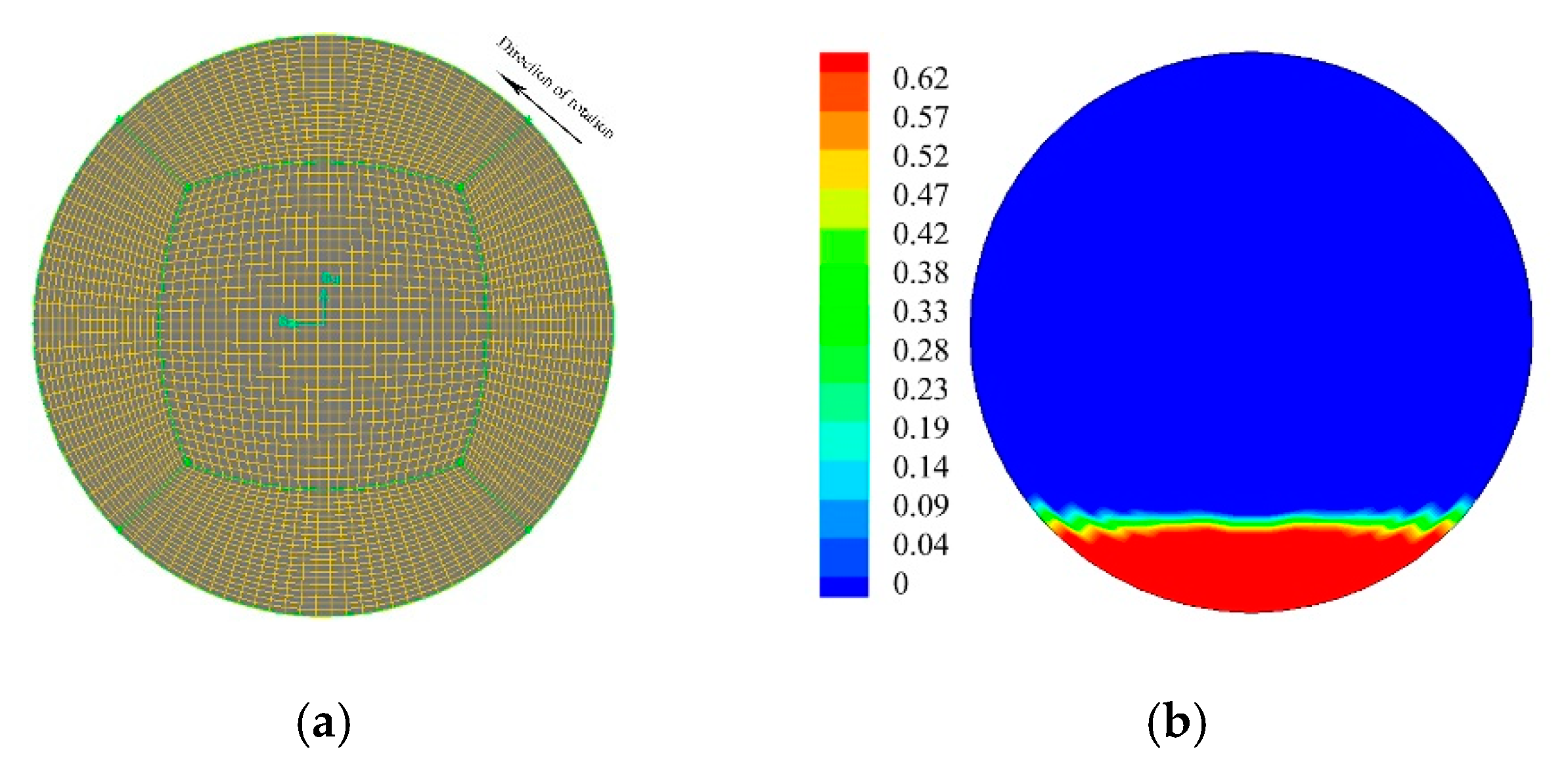
The movements of the wastes were tested on the side of the kiln to further determine the operating conditions of the kiln. Different initial conditions (e.g., rotating speed and particle diameter) were used to test the presented numerical model. The simulation parameters are shown in Table 3. The simulations were performed in a two-dimensional rectangular space using the Computational Fluid Dynamics (CFD) code. The computational mesh is shown in Figure 6a. The Euler multiphase method assumes that both the gas phase and the particle phase are incompressible continuous fluid. The interfacial force between particles and the kiln wall is described by particle dynamics theory. The two-phase distribution of the initial state is shown in Figure 6b.
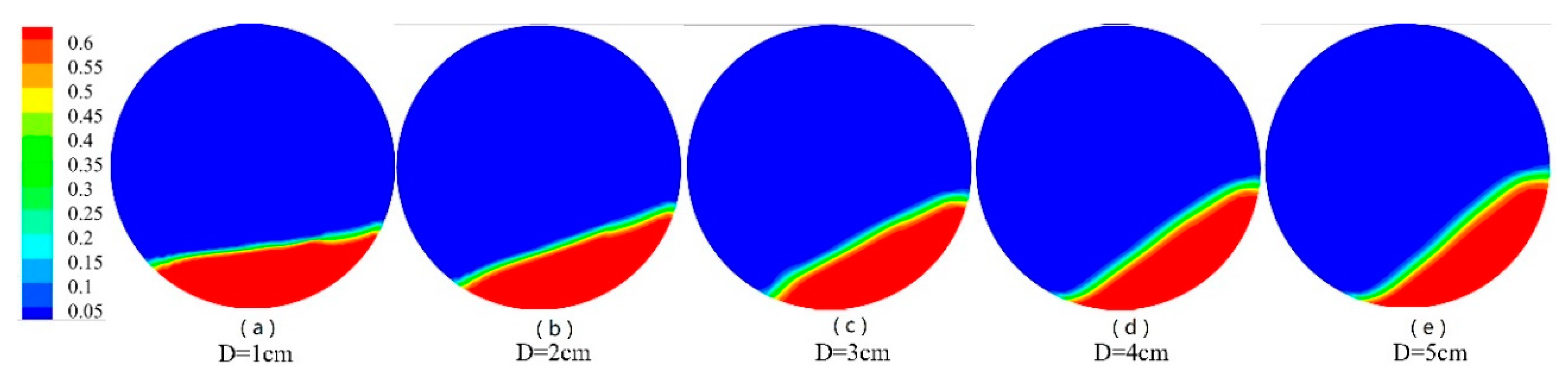
At the initial moment, the particle surface tends to be flat and evenly distributed at the bottom of the rotary kiln. The volume distribution under different particle diameters in stable state is shown in Figure 7, Figure 8 and Figure 9. The results showed the surface of the material presented an inclined angle to the horizontal plane. The material surface gradually tilted and became slightly S-shaped. With the increase of the rotational speed and the diameter of the particle, the particle movement accelerated and experienced sliding, slumping, rolling, cascading and cataracting movements. Centrifugal motion did not occur because of the rotational speed limit. When the particle diameter was 1 cm, the particle movement was only slumping, and when the particle diameter was 5 cm, the particle movement could achieve a cataracting motion.
The rolling bed is preferred in most cases; it is beneficial to improve the heat transfer between the material beds and ensure that the waste is fully mixed and incinerated [24]. In addition, the operation speed of the rotary kiln itself should not be excessively large; otherwise, the transmission structure could have large power consumption. Given that the particle state was rolling and cascading, which is suitable for the rotary kiln working condition, the diameter of the wastes should not be extremely large, and the rotational speed of the rotary kiln should not be exceedingly fast. Therefore, the rotary kiln rotation speed was determined to be 3 rpm.
The velocity vector of particles can directly reflect the motion characteristics of particles in the kiln. The particle area is evidently layered, and the surface speed of the material is considerably larger than the internal stacking speed (Figure 10). This layer is the active layer of the material particles, which is the main area of material mixing and heat exchange. The internal relative speed is small; it is the passive layer, which is the area where the mixing and heat exchange are weak. As shown in Figure 10, the direction of the particle velocity in the active layer is opposite to the direction of the kiln wall movement. When the particles reach the bottom, they begin to change direction in accordance with the movement direction of the kiln wall. The velocity direction of particles in the passive layer is the same as that of the kiln wall, and the particles re-enter the active layer of the surface when they reach the top of the material bed on the right side. The velocity at the free surface of the particle is large, and the velocity vector at the top of the active layer is at an angle to the bed surface. Thus, particle collisions may occur at the upper right of the rotary kiln. The particles fly out under the action of rotational inertia and rejoin the material layer under the influence of gravity, which affects the surface of the active layer. The simulation results are consistent with the material movement theory of the rotary kiln.
4.2. Numerical Simulation of Waste Rotary Incineration
Computational fluid dynamics was used to formulate a 3D steady combustion problem. Figure 11 shows the geometric model and boundary conditions of the simulated rotary kiln. The simulated rotary kiln was assumed to be cylindrical. The meshes of the rotary kiln were generated by Gambit with 1,100,000 cells. The actual diameter and length of the rotary kiln were 1200 and 8000 mm, respectively. For simplicity, only the diesel oil and the mixed waste inlet were set in front of the kiln. Both inlets were 325 mm in diameter. The inclination angle of the rotary kiln was 1.5°, and the rotational speed was 3 rad/min.
Fuel combustion is a complex phenomenon that includes physical and chemical exchanges, multi-phase flow, heat transfer, momentum transfer, and mass transfer. The Eulerian–Lagrangian model was used to describe the flow of the gas and particle phases, and RNG model took into account the rotational effect of material in the kiln. P-1 radiation model was used to describe the radiation heat transfer in the rotary kiln. The discrete model was used to solve the coupling of heat, mass and momentum between the phases. The particle size obeyed the Rosin–Rammler distribution from 1 to 5 cm. The initial data of solid wastes and diesel fuel were added to create a PDF file for non-premixed combustion. The SIMPLEC algorithm was chosen for the pressure–velocity coupling. The inlet parameters used for the four simulation cases are shown in Table 4.
Figure 12 shows the temperature curves in the kiln under three calculated cases of burning diesel oil only. The results showed that the three cases had almost the same trend of temperature change. As the mass flow of diesel oil increased, the temperature gradually rose in the kiln. The maximum combustion temperature of diesel oil with a mass flow rate of 0.04 kg/s reached 1400 °C. This temperature may have exceeded the ash melting point; thus, the ash became molten, and slag formed on the kiln wall. The combustion temperature of diesel oil with a mass flow rate of 0.02 kg/s was relatively low, and the temperature in the kiln was only 700 °C, which may have resulted in the insufficient combustion of the wastes. The temperature field with a mass flow rate of 0.03 kg/s was moderately long, and the temperature in the middle of the flame reached 1200 °C. A large central combustion zone was formed at a distance of 2 m from the kiln inlet, which was conducive to the full mixing combustion of the wastes. The outlet temperature of the kiln was less than 1000 °C. Diesel fuel with a mass flow rate of 0.03 kg/s can not only maintain a high combustion temperature but could also save fuel.
The temperature field of the rotary kiln with waste combustion was simulated, as shown in Figure 13 and Figure 14. The diesel and waste side are shown in Figure 11. The rotary kiln had two high-temperature zones. One zone was obtained by diesel oil injection and combustion, and the other one, which was obtained by mixed wastes that roll over and forward in the axial direction, was burned by gas from the diesel oil combustion of the rotary kiln. The temperature of the material gradually decreased from top to bottom. The lower temperature at the bottom of the kiln was due to the cascading movement of the waste, which burned on the surface of the bed. The heat released by waste combustion was relatively low. The diesel oil combustion temperature was high, and the wastes were rapidly heated in the kiln. The temperature of the wastes gradually rose, reaching the ignition temperature at a distance of 2 m from the kiln inlet, and the wastes began to burn. Then, the fuel bed went into the main combustion stage. The temperature of the flame area was up to 900 °C, and the mixed wastes could be sufficiently burned before leaving the kiln.
Figure 13 and Figure 14 show that the material moved forward along the axial direction in the kiln, and the diesel oil and wastes reached the highest temperature in the range of 1–3 m, where combustion was sufficient. The diesel oil reached the highest temperature at 2 m from the front of the kiln, and the solid wastes reached the highest temperature at 3 m.
Figure 15 shows the gas mass distribution curve on the centerline of the waste inlet (Figure 10). The study of the distribution of CO concentration in the rotary kiln could obtain the combustion status inside the kiln. The CO in the kiln was mainly derived from the pyrolysis of the wastes. The CO concentration was mainly concentrated at 1.5 m from the waste inlet, whereas the content in other regions was small. Given the sufficient oxygen in the kiln to mix well with the CO, the CO reaction gradually became complete, and the CO content at the final outlet tended to zero. CO2 mainly came from the combustion of volatile matter and fixed carbon and reached a high concentration at 2 m in front of the kiln. From the O2 concentration distribution, the concentration of oxygen from the inlet was reduced due to the large amount of combustion consumption of the volatile matter. In this situation, the incomplete combustion of the waste produced the most CO. In the latter half of the rotary kiln, only a few combustible components existed due to the burning of waste; thus, the oxygen content was high.
5. Engineering Application of Rotary Kiln
The rotary kiln and the entire system have been operated in a pesticide plant in Shandong, China. The incineration system is mainly composed of pretreatment, waste incineration disposal, and a flue gas treatment system. Figure 16 shows the practical engineering application of our rotary kiln.
The incineration disposal disposes the pesticide waste liquid and the solid wastes after pretreatment. Under the continuous rotation of the rotary kiln, the mixed wastes are continuously turned, heated, dried, vaporized and burned in the kiln. The combustion temperature in the rotary kiln is kept at about 850 °C, and the residence time of the wastes in the kiln is more than 1 h. Primary dust removal is performed in high-temperature cyclone separator to reduce the particle content in flue gas produced by combustion. After dust removal, the gas enters the secondary combustion chamber. The gas products of the rotary kiln are mixed with the combustion-supporting air of the secondary combustion chamber, and the unburned combustible gas in the rotary kiln is completely burned to remove the toxic organic component. The combustion temperature of the second combustion chamber reaches 1100 °C, and the residence time of the flue gas in the second combustion chamber is no more than 2 s. The discharged gas enters the flue gas treatment system.
The flue gas treatment system is composed of heat exchanger, air preheater, quench tower, activated carbon and a calcium oxide injection system, baghouse, and wet desulphurization. The flue gas discharged from the second combustion chamber initially enters the heat exchanger and air preheater, which can fully utilize the waste heat of high-temperature flue gas, save energy and reduce consumption. The outlet gas temperature is 500–550 °C. Thereafter, the flue gas enters the quench tower. The high-temperature flue gas contacts directly with the atomized cooling water in the quench tower, and the flue gas temperature drops rapidly to 200 °C within 1 s, thereby avoiding dioxin regeneration. Before the flue gas from the quenching tower enters the baghouse, calcium oxide and activated carbon are sprayed successively into the flue. The calcium oxide is used to neutralize the acidic substances in the flue gas. The activated carbon is used to absorb the heavy metal and dioxins in the flue gas. In the baghouse, the suspended particles in the flue gas are intercepted by the filter bag and discharged in the form of fly ash. The flue gas enters the wet absorption tower of the desulphurization unit and contacts with sprayed limestone slurry droplets. The acid substances in the flue gas are absorbed.
An Atmos FIR Fourier infrared multicomponent gas analyzer was used to measure the concentration of SOX, NOX and HCl at the chimney outlet according to GB/T16157-1996. In order to ensure the measurement accuracy, the gas analyzer was calibrated with the target standard gas before measuring. Similarly, automatic smoke sampler with sampling gun was used to measure dust. According to the USA EPA23a method, flue gas sampling was isokinetically collected, and dioxins were preprocessed and measured [29]. The final flue gas concentration (Table 5) meets the emission standard of waste incineration.
The main power consumption equipment in the incineration process of the rotary kiln re the screw conveyor, the motor driving device of the rotary kiln, the draft fan, the ignition burner, the secondary burner, the blower, the slag discharging motor, the quench pump, the lye pump and so on. The total power of the power consumption equipment is 98.29 kW. The hourly waste disposal capacity of the rotary kiln is 1000 kg/h. It takes 353 MJ energy to dispose of a ton of waste. The low calorific value of diesel oil is 42 MJ/L. The diesel oil consumption is 200 L/h. The economic cost of the rotary kiln incineration system mainly includes equipment operation cost, diesel fuel cost, and maintenance cost. The rotary kiln works continuously for 10 h. The power consumption of a rotary kiln is 982.9 kWh per day. The diesel oil consumption per day is 2000 L. There are three workers in total. It costs 691 RMB to treat a ton of waste.
6. Conclusions
A large amount of liquid and solid wastes generated during pesticide production are urgently needed for disposal. A co-incineration scheme for mixing multi-component wastes in a rotary kiln was proposed for waste disposal from pesticide production. The co-incineration experimental results showed that the residence time of solid and liquid mixtures in the kiln is more than 1 h, and the clinker ignition loss of the slag is less than 5%. Therefore, the co-incineration of solid and liquid wastes is feasible. A numerical study of different particle diameters and different wall rotational speeds was performed to reproduce the configurations of solid flows (i.e., sliding, slumping, rolling, cascading, cataracting, and centrifuging). The rolling or cascading mode was selected as the best operating condition. The numerical simulation revealed the combustion interactions of the co-incineration of mixed wastes, and the results showed that the co-incineration of solid and liquid wastes is feasible by adding auxiliary fuel. The rotary kiln incineration can keep the kiln temperature, mass residue and pollutants within the allowable range. Finally, the rotary kiln incineration process and flue gas treatment process were operated and commissioned. The liquid and solid wastes can be completely burned, and the flue gas concentration after treatment can meet the emission standard of waste incineration.
Author Contributions
Investigation, B.Z. and J.H.; methodology, B.Z.; software, C.H.; data curation, W.C.; writing—original draft, J.H.; writing—review and editing, B.Z.
Funding
This research was funded by Key Research and Development Program of Shandong Province of China (No. 2019GHY112002).
Conflicts of Interest
The authors declare no conflict of interest.
Nomenclature
| Ash content of the mixed waste, % | Static pressure, Pa | ||
| Arrhenius type pre-exponential factor | Partial pressure of oxidant species in the gas, Pa | ||
| Surface area of the particle, m2 | Calorific value of mother liquor of methomyl | ||
| Arrhenius factor | Calorific value of solid composition, MJkg−1 | ||
| Carbon content in mixed waste, % | Calorific value of total solid wastes, MJkg−1 | ||
| Diffusion rate coefficient | Calorific value of total mixed waste, MJkg−1 | ||
| Internal energy, Jkg−1 | Particle velocities, ms−1 | ||
| Activation energy, Jmol−1 | Gas velocities, ms−1 | ||
| Fixed carbon of the mixed waste, % | Particle velocities, ms−1 | ||
| Additional forces, N | Mass source, kgs−1 | ||
| Mixing fraction | Temperature, K | ||
| Mixture fraction of the secondary stream diesel oil | Particle temperature, K | ||
| Mass fraction of evaporating material | Volatiles content of the wastes, % | ||
| Mass fraction of solid composition in the total solid wastes | Velocity vector in the x direction, ms−1 | ||
| Mass fraction of mother liquor in the total waste | Velocity vector in the y direction, ms−1 | ||
| Mixture fraction of oxidant | Velocity vector in the z direction, ms−1 | ||
| Mixture fraction of the waste fuel | Mass fraction for element | ||
| Mass fraction of total solid wastes in the total waste | Elemental mass fraction of fuel inlet | ||
| Mass fraction of the volatiles in the initial particle | Elemental mass fraction of oxidant inlet | ||
| Hydrogen content in wastes, % | Stress tensor, Pa | ||
| Kinetic rate, s−1 | Kinetic rate, s−1 | ||
| Moisture content of the wastes, % | Dynamic viscosity, Pas | ||
| Particle mass, kg | Kronecker symbol | ||
| Initial particle mass, kg | Gas phase density, kgm−3 | ||
| Nitrogen content in mixed waste, % | Thermal conductivity, Wm−1 K−1 | ||
| Oxygen content in mixed waste, % | Density of particle phase, kgm−3 | ||
| Gravitational body force, ms−2, Greek letters |
References
- Jin, F.; Wang, J.; Shao, H. Pesticide use and residue control in china. J. Pestic. Sci. 2010, 35, 138–142. [Google Scholar] [CrossRef]
- Chen, Z.L.; Dong, F.S.; Jun, X.U. Management of pesticide residues in China. J. Integr. Agric. 2015, 14, 2319–2327. [Google Scholar] [CrossRef]
- Xu, D.; Wang, S.; Zhang, J. Supercritical water oxidation of a pesticide wastewater. Chem. Eng. Res. Des. 2015, 94, 396–406. [Google Scholar] [CrossRef]
- Renou, S.; Givaudan, J.G.; Poulain, S. Landfill leachate treatment: review and opportunity. J. Hazard. Mater. 2008, 150, 468–493. [Google Scholar] [CrossRef] [PubMed]
- Gao, Q.; Wang, L.; Li, Z. Adsorptive Removal of Pyridine in Simulation Wastewater Using Coke Powder. Processes 2019, 7, 459. [Google Scholar] [CrossRef]
- Migliori, M.; Catizzone, E.; Giordano, G. Pilot Plant Data Assessment in Anaerobic Digestion of Organic Fraction of Municipal Waste Solids. Processes 2019, 7, 54. [Google Scholar] [CrossRef]
- Nie, Y. Development and prospects of municipal solid waste (MSW) incineration in China. Front. Environ. Sci. Eng. China 2008, 2, 1–7. [Google Scholar] [CrossRef]
- Jabłońska, B.; Kiełbasa, P.; Korenko, M.; Dróżdż, T. Physical and Chemical Properties of Waste from PET Bottles Washing as A Component of Solid Fuels. Energies 2019, 12, 2197. [Google Scholar] [CrossRef]
- Tabasová, A.; Kropáč, J.; Kermes, V. Waste-to-energy technologies: Impact on environment. Energy 2012, 44, 146–155. [Google Scholar] [CrossRef]
- Ghouleh, Z.; Shao, Y. Turning municipal solid waste incineration into a cleaner cement production. J. Clean. Prod. 2018, 195, 268–279. [Google Scholar] [CrossRef]
- Guo, Y.; Glad, T.; Zhong, Z. Environmental life-cycle assessment of municipal solid waste incineration stocks in Chinese industrial parks. Resour. Conserv. Recycl. 2018, 139, 387–395. [Google Scholar] [CrossRef]
- Chen, H.C.; Zhao, C.S.; Li, Y.W.; Lu, D.F. NOx emission from incineration of organic liquid waste in a circulating fluidized bed. Korean J. Chem. Eng. 2007, 24, 906–910. [Google Scholar] [CrossRef]
- Ma, J.; Liu, D.; Chen, Z.; Chen, X. Agglomeration characteristics during fluidized bed combustion of salty wastewater. Powder Technol. 2014, 253, 537–547. [Google Scholar] [CrossRef]
- Wang, N.Y.; Chun, H.S.; Peite, C. Environmental effects of sewage sludge carbonization and other treatment alternatives. Energies 2013, 6, 871–883. [Google Scholar] [CrossRef]
- Hu, S.; Ma, X.; Lin, Y. Thermogravimetric analysis of the co-combustion of paper mill sludge and municipal solid waste. Energy Convers. Manag. 2015, 99, 112–118. [Google Scholar] [CrossRef]
- Lin, H.; Ma, X. Simulation of co-incineration of sewage sludge with municipal solid waste in a grate furnace incinerator. Waste Manag. 2012, 32, 561–567. [Google Scholar] [CrossRef]
- Zhong, Q.; Zhang, J.; Yang, Y. Thermal Behavior of Coal Used in Rotary Kiln and Its Combustion Intensification. Energies 2018, 11, 1055. [Google Scholar] [CrossRef]
- Shi, H.; Si, W.; Li, X. The Concept, Design and Performance of a Novel Rotary Kiln Type Air-Staged Biomass Gasifier. Energies 2016, 9, 67. [Google Scholar] [CrossRef]
- Weinberg, A.V.; Varona, C.; Chaucherie, X. Extending refractory lifetime in rotary kilns for hazardous waste incineration. Ceram. Int. 2016, 42, 17626–17634. [Google Scholar] [CrossRef]
- Bai, Y.; Bao, Y.B.; Cai, X.L. Feasibility of disposing waste glyphosate neutralization liquor with cement rotary kiln. J. Hazard. Mater. 2014, 278, 500–505. [Google Scholar] [CrossRef]
- Huber, F.; Blasenbauer, D.; Mallow, O. Thermal co-treatment of combustible hazardous waste and waste incineration fly ash in a rotary kiln. Waste Manag. 2016, 58, 181–190. [Google Scholar] [CrossRef] [PubMed]
- Bujak, J. Thermal treatment of medical waste in a rotary kiln. J. Environ. Manag. 2015, 162, 139–147. [Google Scholar] [CrossRef] [PubMed]
- Bujak, J. Thermal utilization (treatment) of plastic waste. Energy 2015, 90, 1468–1477. [Google Scholar] [CrossRef]
- Mellmann, J. The transverse motion of solids in rotating cylinders—forms of motion and transition behavior. Powder Technol. 2001, 118, 251–270. [Google Scholar] [CrossRef]
- Wang, M.; Liao, B.; Liu, Y. Numerical simulation of oxy-coal combustion in a rotary cement kiln. Appl. Therm. Eng. 2016, 103, 491–500. [Google Scholar] [CrossRef]
- Badzioch, S.; Hawksley, P.G.W. Kinetics of Thermal Decomposition of Pulverized Coal Particles. Ind. Eng. Chem. Process Des. Dev. 1970, 9, 521–530. [Google Scholar] [CrossRef]
- Baum, M.M.; Street, P.J. Predicting the Combustion Behaviour of Coal Particles. Combust. Sci. Technol. 1971, 3, 231–243. [Google Scholar] [CrossRef]
- Ghenai, C.; Lin, C.X.; Ebadian, M.A. Numerical Investigation of Oxygen-Enriched Pulverized Coal Combustion. Heat Transf. 2003, 2. [Google Scholar] [CrossRef]
- Pham, M.T.N.; Anh, H.Q.; Nghiem, X.T. Characterization of PCDD/Fs and dioxin-like PCBs in flue gas from thermal industrial processes in Vietnam: A comprehensive investigation on emission profiles and levels. Chemosphere 2019, 225, 238–246. [Google Scholar] [CrossRef]
Figure 1.
Solid wastes and liquid wastes in the pesticide production. (a) Sludge; (b) activated carbon; (c) pendimethalin; (d) amyl amine; (e) kettle residue; (f) aniline; (g) floccus; (h) kettle substrate; (i) and mother liquor of methomyl.
Figure 1.
Solid wastes and liquid wastes in the pesticide production. (a) Sludge; (b) activated carbon; (c) pendimethalin; (d) amyl amine; (e) kettle residue; (f) aniline; (g) floccus; (h) kettle substrate; (i) and mother liquor of methomyl.

Figure 2.
Experimental measurement equipment. (a) Constant temperature oven; (b) muffle furnace; (c) scanning electron microscope; (d) calorimeter; (e) crucible holder; and (f) electronic balance.
Figure 2.
Experimental measurement equipment. (a) Constant temperature oven; (b) muffle furnace; (c) scanning electron microscope; (d) calorimeter; (e) crucible holder; and (f) electronic balance.

Figure 3.
Integral structure of the experimental rotary kiln.

Figure 4.
Clinker ignition loss.

Figure 5.
Clinker with various particle sizes in the different batches.

Figure 6.
Profile of the rotary kiln. (a) Rotary kiln mesh; (b) volume distribution of materials at the initial time.
Figure 6.
Profile of the rotary kiln. (a) Rotary kiln mesh; (b) volume distribution of materials at the initial time.

Figure 7.
Volume distribution under different particle diameters (rotation speed = 2 rpm).

Figure 8.
Volume distribution under different particle diameters (rotation speed = 3 rpm).

Figure 9.
Volume distribution under different particle diameters (rotation speed = 4 rpm).

Figure 10.
Velocity vector field of particles.

Figure 11.
Geometry model of the rotary kiln.

Figure 12.
Temperature curve of diesel oil combustion under different mass flow rates.

Figure 13.
Temperature field of waste side and diesel side in the rotary kiln.

Figure 14.
Temperature field of different cross sections in the rotary kiln (each section interval is 1 m).
Figure 14.
Temperature field of different cross sections in the rotary kiln (each section interval is 1 m).

Figure 15.
Gas mass fraction in the rotary kiln.

Figure 16.
Incineration process and flue gas treatment process.


Table 1.
Proximate and ultimate analyses of wastes.
| Proximate Analysis (wt%) | Ultimate Analysis (wt%) | Qgr,ad (MJ/kg) | ||||||
|---|---|---|---|---|---|---|---|---|
| Mad | Aad | FCad | Vad | Cad | Had | Oad | Nad | |
| 23.6 | 20.4 | 20 | 36 | 56.74 | 2.20 | 36.20 | 4.86 | 4.05 |
Table 2.
Daily production, mass fraction and calorific value of the material components.
| Material Name | Daily Production/kg | Mass Fraction/% | Calorific Value/(103 kJ/kg) |
|---|---|---|---|
| Aniline | 20 | 0.38 | 25.8 |
| Amyl amine | 10 | 0.19 | 36.6 |
| Kettle residue | 100 | 1.94 | 23.7 |
| Kettle substrate | 15 | 0.29 | 38.4 |
| Floccus | 70 | 1.36 | 42.0 |
| Pendimethalin | 100 | 1.94 | 25.2 |
| Activated carbon | 230 | 4.47 | 18.5 |
| Sludge | 600 | 11.66 | 4.5 |
| Solid wastes in total 1 | 1145 | 22.26 | 14.1 |
| Mother liquor of methomyl | 4000 | 77.74 | 1.2 |
| Wastes in total 2 | 5145 | 100 | 4.05 |
1 Total solid wastes indicate the sum of all materials without the mother liquor of methomyl. 2 Total waste indicates the sum of all materials.
Table 3.
Parameters of numerical simulation.
| Description | Value | ||||
|---|---|---|---|---|---|
| Rotating speed (rpm) | 2 | 3 | 4 | ||
| Particle diameter (cm) | 1 | 2 | 3 | 4 | 5 |
| Rotary kiln diameter (m) | 1.2 | ||||
| Solid density (kg/m3) | 1150 | ||||
| Air density (kg/m3) | 1.225 | ||||
| Air pressure (105 N/m2) | 1.01 | ||||
| Particle–wall restitution coefficient | 0.8 | ||||
| Particle–particle restitution coefficient | 0.9 | ||||
Table 4.
Inlet parameters.
| Temperature (k) | Case (1) | Case (2) | Case (3) | Case (4) | |
|---|---|---|---|---|---|
| Mass Flow Rates (kg/s) | |||||
| Air | 300 | 1.5 | 1.5 | 1.5 | 1.5 |
| Diesel inlet | 500 | 0.02 | 0.03 | 0.04 | 0.03 |
| Waste inlet | 300 | 0 | 0 | 0 | 0.06 |
Table 5.
Measured value of pollutant concentration in flue gas.
| Pollutants | Daily Average Concentration | Chinese Standard 18485–2014 |
|---|---|---|
| Dust/(mg/Nm3) | 15 | 20 |
| SOx/(mg/Nm3) | 40 | 80 |
| NOx/(mg/Nm3) | 120 | 250 |
| HCl/(mg/Nm3) | 25 | 50 |
| Dioxins/(ngTEQ/Nm3) | 0.015 | 0.1 |
© 2019 by the authors. Licensee MDPI, Basel, Switzerland. This article is an open access article distributed under the terms and conditions of the Creative Commons Attribution (CC BY) license (http://creativecommons.org/licenses/by/4.0/).
Share and Cite
MDPI and ACS Style
Zhang, B.; He, J.; Hu, C.; Chen, W. Experimental and Numerical Simulation Study on Co-Incineration of Solid and Liquid Wastes for Green Production of Pesticides. Processes 2019, 7, 649. https://doi.org/10.3390/pr7100649
AMA Style
Zhang B, He J, Hu C, Chen W. Experimental and Numerical Simulation Study on Co-Incineration of Solid and Liquid Wastes for Green Production of Pesticides. Processes. 2019; 7(10):649. https://doi.org/10.3390/pr7100649
Chicago/Turabian StyleZhang, Bin, Jinjie He, Chengming Hu, and Wei Chen. 2019. "Experimental and Numerical Simulation Study on Co-Incineration of Solid and Liquid Wastes for Green Production of Pesticides" Processes 7, no. 10: 649. https://doi.org/10.3390/pr7100649
Note that from the first issue of 2016, this journal uses article numbers instead of page numbers. See further details here.