Modeling and Simulation Studies of a Novel Coupled Plug Flow Crystallizer for the Continuous Separation of Conglomerate-Forming Enantiomers


School of Engineering, University of Aberdeen, Aberdeen AB24 3UE, UK
Processes 2018, 6(12), 247; https://doi.org/10.3390/pr6120247
Submission received: 15 October 2018
/
Revised: 19 November 2018
/
Accepted: 27 November 2018
/
Published: 1 December 2018
(This article belongs to the Special Issue Recent Advances in Population Balance Modeling)
Abstract
:Separation of enantiomers is a major concern in pharmaceutical industries due to the different therapeutic activities exhibited by the enantiomers. Preferential crystallization is an attractive means to separate the conglomerate-forming enantiomers. In this work, a simulation study is presented for a proposed novel preferential crystallization configuration that involves coupled plug flow crystallizers (PFCs). The PFCs are coupled through liquid phase exchange which helps the enrichment of the preferred enantiomer in the liquid phase. A set of coupled population balance equations (PBEs) are used to describe the evolution of the crystal size distribution (CSD) in the PFCs. The PBEs and the relevant mass balance equations are solved using the high-resolution finite-volume method. The simulation results predict that the proposed configuration has higher productivity compared to the currently used crystallization configurations while maintaining the same level of purity. Moreover, the effect of process variables, such as the extent of liquid phase exchange and the location of the PFC where liquid phase exchange occurs, are studied. The insights obtained from this simulation study will be useful in design, development, and optimization of such novel crystallization platforms.
1. Introduction
Chiral molecules or enantiomers are ubiquitous in biological systems and therefore are of great interest to pharmaceutical, food and agrochemical industries. More than half of the new molecular entities (NME) approved by the United States Food and Drug Administration (FDA) between 2010 and 2016 are chiral compounds [1], and with the current trends it is anticipated that in future the NMEs will be dominated by chiral molecules. The chiral molecules occur in pairs which are the non-superimposable mirror images of each other. The chirality is the result of the presence of a single chiral atom center in the chiral molecule. These molecules exhibit identical physical or chemical properties in a nonchiral environment; however, they can exhibit vastly different biological activities in a chiral environment such as human body. For instance, -naproxen is used to treat arthritis, while its mirror image -naproxen can be highly toxic to the liver [2]. Thus, it is critical for the pharmaceutical industries that the chiral drugs are produced in optically pure form.
Although enantioselective or asymmetric synthesis would be ideal, the number of highly selective reactions on an industrially relevant scale is still limited [3]. Therefore, chiral resolution, the separation of a racemic (equimolar) mixture into its enantiomers, is the most widely used approach to produce preferred enantiomers. Many of the available resolution techniques such as chromatography [4,5,6,7] and membrane separation [8,9,10], typically deliver the product in diluted form in the liquid phase often requiring a crystallization step for producing the desired solid product [11]. In contrast, preferential crystallization can be directly used as an attractive and efficient means to separate the racemic mixtures due to its ability to provide high purity solid products. However, preferential crystallization can only be used for separating conglomerate-forming systems (which is up to 10% of the available enantiomers) [12]. In a conglomerate-forming system, the two enantiomers crystallize as distinct enantiopure solid phases even when both enantiomers are present in the mother liquor. In contrast, an additional crystal phase containing equimolar mixture of both the enantiomers can be found for racemic compounds.
In preferential crystallization, it is important to prevent the nucleation and growth of the counter enantiomer. However, this can become increasingly difficult if the supersaturation level of the counter enantiomer is high in the crystallizer. This problem can be alleviated by a liquid phase exchange between two coupled crystallizers where both the enantiomers are crystallized separately [13,14,15]. Moreover, when chiral compound can be racemized in solution, a further alleviation of the supersaturation of the counter enantiomer can be obtained. Solution racemization is the interconversion of the enantiomer molecules towards equimolar composition in the solution when any deviation in concentration is encountered. Such racemization has the added advantage that it can significantly increase the enantiopure product yield as it also transforms the counter enantiomer solute into preferred enantiomer crystals. Recently it has been shown that such a process can be applied in a continuous mixed suspension mixed product removal (MSMPR)-type configuration [16]. Such combinations of solution racemization and crystallization are termed deracemization processes.
Viedma ripening or attrition enhanced deracemization is another such deracemization process [17] It has been demonstrated by Viedma [17] and later by Noorduin [18] that batch-wise symmetry breaking towards a chirally pure solid is possible through a combination of solution racemization and grinding in the presence of glass beads. Since then there has been many studies on this attrition enhanced ripening for chiral resolution [11,19,20]. In recent years, it has been further demonstrated that a complete deracemization of the solid phase can be achieved via a batch-wise combination of solution racemization and temperature cycling [21,22,23,24]. An industrially easy way to apply temperature cycling-enhanced deracemization was lately proposed where instead of applying temperature cycles, the suspension is circulated between two vessels—one kept at high temperature where partial dissolution of the suspension take place, while the other kept at low temperature to promote crystal growth [25].
In recent years, the pharmaceutical industry has intensified efforts to adopt continuous manufacturing for its significant benefits as compared to the prevalent batch processing. The continuous crystallizer, when operated under a controlled steady state, in theory provides no variability in process conditions such as temperature, concentration, as well as product properties such as purity, crystal size distribution (CSD) etc. over time, leading to greater reproducibility. Although MSMPRs remain the most used platform for continuous crystallization largely due to familiarity in terms of operation and control, they possess weaknesses for the application of crystallization. These include non-uniform temperature control, highly localized shear regions due to agitators, challenges with handling solids at transfer lines, and non-linear scalability [26]. Plug flow crystallizers (PFCs) such as tubular crystallizer [27,28,29,30,31] or continuous oscillatory baffled crystallizer (COBC) [32,33] have been used for crystallization processes. However, to the best of our knowledge, they have not been used for continuous separation of enantiomers.
In this work, novel crystallizer configurations based on PFC through innovative process design has been proposed for the continuous separation of the conglomerate-forming enantiomers. This novel configuration involves two PFCs coupled through solid free liquid phase exchange and the crystallization of the enantiomers takes place in two crystallizers separately. A population balance model [14,34,35] of the process has been developed and simulation results for the model compound D-/L-threonine are compared with the widely used coupled batch and coupled MSMPR-type crystallizers. Effect of various operating conditions such as amount and location of liquid exchange and seed mass has been presented as well.
2. Available Coupled Preferential Crystallizer Configurations
In this section, we briefly discuss some of the widely used coupled crystallizer configurations for the preferential crystallization of enantiomers for which liquid phase racemization is not available. The preferential crystallization technique involves selective crystallization of the preferred enantiomer from a racemic supersaturated mother liquor using only the addition of enantiopure seed crystals. There are various configurations of preferential crystallization including those which use the liquid phase exchange between the two coupled crystallizers for improved productivity and yield.
Some of the coupled preferential crystallizer configurations widely used for the separation of conglomerate-forming enantiomers are shown in Figure 1. These are coupled mixed suspension mixed product removal (CPC-MSMPR) tanks [15,36], coupled preferential crystallizer (CPC) configuration that runs in batch mode [37,38] and coupled preferential crystallizer with dissolution of the counter enantiomer in one tank (CPC-D) [14]. In CPC-MSMPR configuration, both the MSMPRs are filled with the supersaturated solution with racemic composition at the start of the process. Then, the feed slurries containing racemic solution and homochiral seed crystals of opposite enantiomers at the crystallization temperature are continuously fed to the MSMPRs. This promotes growth and nucleation of the opposite enantiomers in the two MSMPRs. The continuous supply of the feed containing seed crystals can be ensured, for instance, by ultrasonic comminution [39] or wet-mill grinding [40] of crystals, withdrawn from the bottom of the MSMPR crystallizers. The product slurries are withdrawn from the bottom the MSMPRs at the same rate as the feed slurries so that same volume of slurry is maintained in each MSMPR during the operation. Coupling of the two MSMPRs is done using solid free liquid phase exchange between the two MSMPRs. The CPC configuration can be considered as the batch version of the CPC-MSMPR configuration. Therefore, no continuous feed and product streams are present. The process starts with the introduction of the homochiral seed crystals to the vessels at the beginning and it can run until supersaturation is depleted or counter enantiomer appears. The CPC-D configuration is also run in batch mode where two different temperatures are maintained in two tanks. The condition for Tank 1 is similar to the CPC configuration and the temperature maintained there is lower than the saturation temperature. Therefore, selected crystallization of the seeded enantiomer takes place in Tank 1. However, Tank 2 is fed with racemic solid and the saturation temperature is maintained. Due to the liquid phase exchange, Tank 2 becomes undersaturated with respect to the enantiomer that is being crystallized in Tank 1 (e.g., as shown in Figure 1) leading to dissolution of that enantiomer in Tank 2. Harvest period for this configuration starts after complete dissolution of the counter enantiomer (e.g., ) in Tank 2 and continues until counter enantiomer appears in Tank 1 [14].
All these configurations have their own limitations and shortcomings. The CPC configuration suffers from low productivity due to the depletion of the supersaturation with time [14]. While CPC-D configuration has higher productivity compared to CPC, here the crystallization harvest time is limited by the appearance of the counter enantiomer [14,35]. The CPC-MSMPR configuration, which is run on continuous mode, has higher productivity than the CPC and CPC-D configurations. However, productivity of this configuration can still be limited due to low processing intensity.
3. Proposed Coupled PFC Configuration
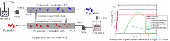
The proposed crystallizer configuration consists of two PFCs where crystallization of different enantiomers is carried out in different crystallizers, e.g., crystallization of in PFC1 and in PFC2. These crystallizers are coupled through liquid phase exchange as shown in Figure 2. Each crystallizer is fed with saturated slurry containing racemic liquid phase and homochiral seed crystals, and cooling crystallization is carried out. The continuous supply of the seed crystals can be maintained by ultrasonic comminution [39] or wet-mill grinding [40] of crystals, withdrawn from the product stream. Product slurry from each PFC is filtered to collect the product crystals. However, crystal free liquid phase rich in enantiomer is obtained from the PFC2 at a suitable location and added to the other PFC1 at the corresponding location so that the depletion of super saturation of the preferred enantiomer can be compensated to some extent. Such exchange of liquid phase mimics the racemization of the liquid phase. A pump with solvent filter can be used to obtain crystal free mother liquor [15]. In order to keep the volumetric flowrate constant along the PFC, the same amount of liquid exchange is carried out. This prevents the change in the residence time of the slurry due to the changes in volumetric flowrate when liquid exchange is introduced. Although the current work assumes ideal plug flow crystallizer, in reality variants of tubular reactors that have provisions for static mixture [27] or oscillatory flow [26,32] can achieve near plug flow condition. A measure of the strength of axial dispersion as compared to the convection transport is given by the Peclet number, defined as
where D is the diffusion coefficient, u is the fluid velocity and is the effective crystallizer length. From Equation (1) it is evident that a high value of Pe reduces the relative importance of the diffusion term leading to the near ideal plug flow behavior. It has been found experimentally that for a flowrate of 100 mL min−1 in a tubular crystallizer having same diameter as discussed in this work and with kenics-type static mixture, the Peclet number is 230 [27]. Therefore, the high value of Pe confirms close to ideal plug flow behavior of the crystallizer. Similar conclusions are obtained in studies on oscillatory baffled crystallizers [41,42]. In this study, it is assumed that the location of the extraction and injection points of the exchange liquid in the PFC is close enough so that they can be approximated as single point for simulation purpose. In reality it can be challenging to achieve the exchange of solution in a single location of the PFC without mixing. However, as shown in Figure 2, the close proximity of the extraction and injection points can be justified based on the argument that there will be negligible or very low mixing of the exchange liquid streams, if the axial dispersion is very low in the tubular crystallizer and the introduction of the exchange liquid takes place in a point located downstream of the point of extraction. Since convection is the dominant mass transfer mechanism, if the introduction of the exchange liquid occurs at the downstream compared to the extraction point, the injected liquid will travel forward along the PFC minimizing the chance of mixing with the extraction stream located upstream.
In conglomerate-forming systems, the crystal phases consist of either pure S enantiomer or R enantiomer. The preferential crystallization of a chosen enantiomer in the PFCs is based on the principle that the nucleation of the enantiomers is an activated process. As a result, when a crystallizer is seeded with preferred enantiomer, the crystallization of the counter enantiomer does not readily occur at low supersaturations. This kinetic advantage resulting from the difference in energy between crystal nucleation and growth processes allows crystallization of the seeded enantiomer while suppressing the crystallization of counter enantiomer. The model equations of the proposed process are discussed next.
4. Model Development
A population balance based model is developed for this coupled PFC system. The population balance equation (PBE) can be derived by writing the number balance of the crystals for the volume element in Figure 3.
The balance equation for the crystal numbers of each enantiomer can be written for the volume element as
here is the number density or crystal size distribution (CSD) of component k and in PFC j and it is to be noted that here the CSD is distributed along the internal coordinates (i.e., crystal size L) as well as external coordinates (e.g., the axial position in the PFC x). A is the cross sectional area of the PFC, is the growth rate of the crystals, is the slurry velocity, is the rate of liquid phase exchange, and denote the extraction and injection points of the exchange liquid, respectively, is the Dirac delta function. The first and second terms on the right-hand side of Equation (3) denote the convective term due the crystal growth and fluid flow, respectively, while the third and fourth terms denote the point source and sink terms, respectively, due to the exchange of liquid. By dividing both sides by and in the limit , the following PBE can be obtained
where is the nucleation rate and S is the supersaturation. The PBE in Equation (4) needs to be supplemented by appropriate mass and energy balance equations. Moreover, the liquid phase exchange will affect the enantiomer concentrations as shown in Figure 3. Similar to the population balance, the mass balance equation can be obtained by writing mass balance for the volume element in Figure 3
here is the concentration of the enantiomer k in liquid phase. It is to be noted that the liquid phase exchange rate is assumed to be the same for both PFCs so that there is no net change in volumetric flow rates. However, this is not a limitation of the model developed. The volume of the crystals is assumed to be negligible as compared to the volume of the solution.
The empirical size-dependent growth rate expression is found to be as follows
where is the temperature dependent rate constant
where is the pre-exponential factor (a constant model parameter). The driving force for crystallization is the supersaturation S which can be expressed as a ratio of the mass fraction and the equilibrium mass fraction of the solute as
here is the mass fraction of each component. This mass fraction can be defined as follows
The solubility of the D-/L-threonine in water for a relatively wide range of temperature and composition range can be expressed by the following expression [14]
The liquid phase consists of several components and its density is approximated by an empirical formula taking into account its composition
where denotes the density of water at a given temperature and , , are constants.
On the other hand, the dissolution rate in undersaturated solution is found to be
In a supersaturated solution, the primary and secondary nucleation contribute to the birth of new particles. The secondary nucleation of an enantiomer is predominant if crystals of that enantiomer are already present, and can be expressed as the function of supersaturation, temperature, and crystal volume as follows:
where is the third moment of distribution for the enantiomer k which can be considered as a measure of crystal volume. The temperature dependent rate constant is expressed by Arrhenius-type equation. On the other hand, the primary nucleation takes place in the clear solution and can be estimated as a function of supersaturation as shown below
here induction time denotes the time lag between the time of first measured concentration decrease in the liquid phase under seeded conditions and the time when the initial degree of supersaturation was reached. It has been found experimentally that can describe the experimental observations for induction time reasonably well [14]. is the sigmoid function that captures the sudden appearance of the nuclei and it depends on the second parameter as
In this work energy balance equation is not solved, rather a natural cooling temperature profile is assumed along the PFC which is established by the cooling jacket. All the equations will form a set of highly coupled PDEs which needs to be solved numerically. The well-established high-resolution finite-volume technique is used for this purpose for its ability to accurately solve the hyperbolic PDEs with discontinuities [43,44,45]. Simulations were carried out using MATLAB computational software (Version 2017a, Mathworks, Inc., Natick, MA, USA, 2017).
5. Results and Discussion
The well-studied D/L-threonine in water is taken as the model system in this study. The required rate expression (growth and nucleation) and the kinetic parameters for this system are experimentally determined and verified by other researchers [14,46]. These kinetic parameters are presented at Table A1 in Appendix A. The vessel size used in the configurations shown in Figure 1 is 0.45 L. The details of the process condition used is shown in Table 1.
On the other hand, the PFC considered in the simulation study has six segments, each segment is 600 mm long with internal diameter of 12.7 mm. The feed flowrate to the PFC is 25 mL min. The mass of the seed used is the same in all configurations (2 g seed/0.45 L of slurry). The temperature at the inlet of the PFC is °C which exponentially decays to °C at the outlet and approximates the natural cooling profile according to the following equation
Such a temperature profile generates high supersaturation near to the entrance and moderate supersaturation towards the end.
The seed distribution is taken as the log-normal distribution as follows
The parameter is the ratio of the mass of seeds and the mass of the control sample given by
where and are the CSD and third moment of the control sample, respectively.
The performance of the crystallizer configurations is compared with respect to the productivity and yield. The productivity of the continuous configurations (i.e., CPC-MSMPR, single PFC and coupled PFC) is defined as
where and are the solid crystal mass flow rate in the product stream and feed stream, respectively and is the enantiomeric excess, which is used as a measure of purity of the product. The purity of the crystal is critical, for instance, in pharmaceutical manufacturing and therefore is used as the weighting factor in the definition of productivity. It ensures that the purity of the product is taken into account.
where is the mass of the solid phase of enantiomorph k in the crystallizer. The equivalent productivity for the CPC and CPC-D configurations is defined as follows
The yield of the crystallization process is used as another performance indicator. It can be defined as the fraction of the solute present in the solution that was obtained as crystal product. Taking into account the purity of the product, the yield of the continuous configurations can be found as
where and are mass flow rates of the enantiomorph k in the liquid phase in the feed stream and in the product stream, respectively. For the CPC and CPC-D configurations, the yield is defined as follows
where is the mass of the enantiomorph k in the racemate. is nonzero only for Tank 2 in CPC-D configuration.
5.1. Product CSD in Coupled PFC Configuration
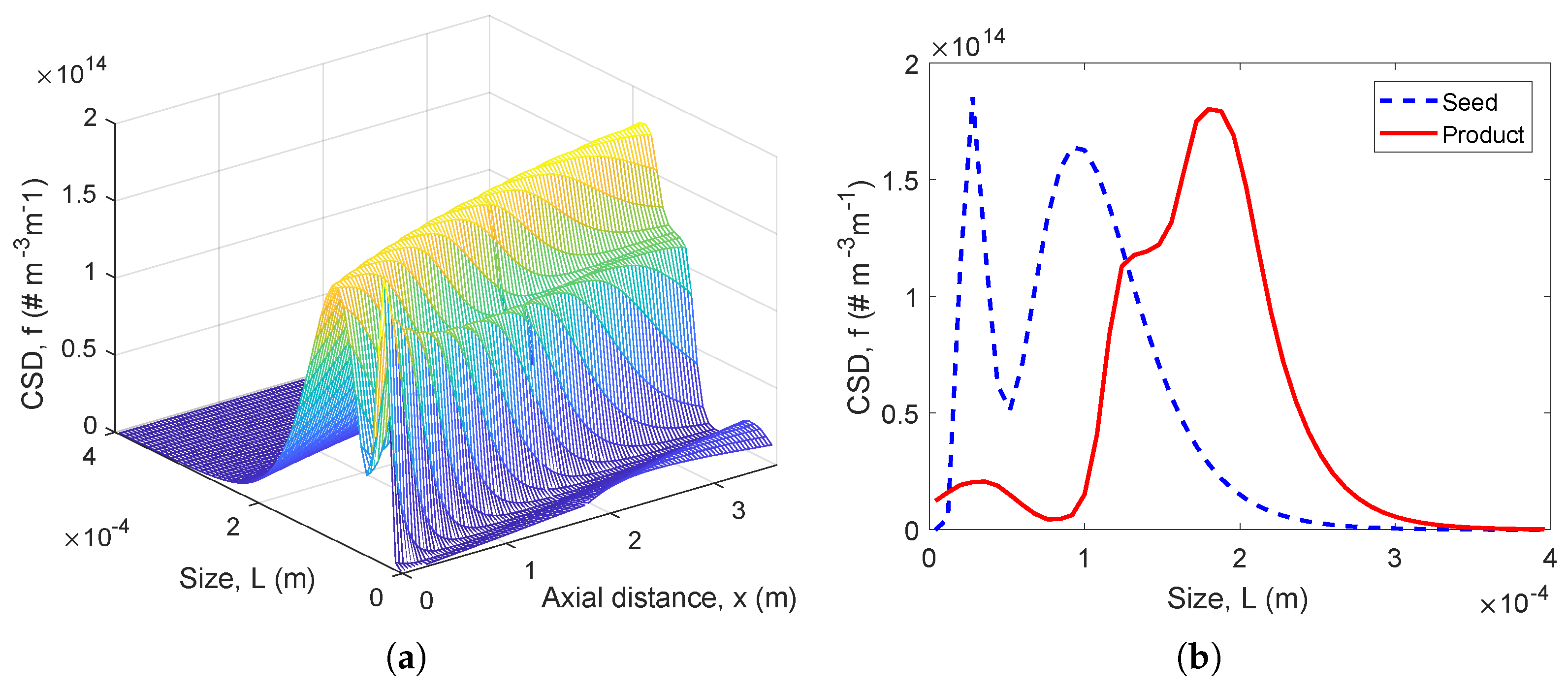
Simulations are carried out in MATLAB for crystallization processes that run for 5 h. In Figure 4a, evolution of the preferred enantiomer CSD along the PFC 1 with liquid exchange is shown. As can be seen, due the supersaturation generated by cooling, the crystals grow as they travel along the PFC. Some nucleation has also taken place as indicated by the small peak near the small sized region. In Figure 4b, final product CSD obtained from the PFC is compared with the seed CSD. Here growth of the seed crystals is evident from the location of the prominent peak of the CSD which moved from about 100 m to 200 m. Please note that CSD obtained form PFC2 is not shown here as it would be similar due to the identical kinetic parameters for both the D-/L-threonine.
5.2. Comparison of Productivity and Yield
A comparison of productivities obtained from various process configuration for the crystallizers, where enantiomer is preferentially crystallized, is presented in Figure 5a. As can be seen, the productivities of the continuous crystallizer configurations, which include the proposed coupled PFC, single PFC and coupled MSMPR configurations, are found to be higher than the batch crystallizer configurations which are the CPC and CPC-D configurations. For comparison purpose, these productivity numbers are scaled to represent a crystallizer volume of 0.45 L. Moreover, the productivities of continuous crystallizer configurations reach steady-state value after about 0.2 h while for the batch configurations the productivities initially increase with time and then diminish after reaching a maximum value corresponding to the process conditions used. These findings are not surprising as in batch configurations, there are no feed steams to replenish the solute concentration in the solution which is depleted due to crystal growth. As a result, the productivities for the batch configurations diminish after certain time. However, among the continuous configurations, the coupled PFC found to be the best performing configuration in terms of productivity for the process parameters used in the simulation. This finding can be attributed to the fact that in principle a PFC approximates a large number of MSMPRs connected in series. In addition, the liquid phase exchange compensates for the depleted concentration of the preferred enantiomer to some extent. The advantage of the liquid phase exchange in coupled PFC can also be seen by comparing its productivity with the single PFC. The productivity of single PFC is lower than the coupled PFC therefore it can be concluded that the liquid phase exchange contributes to the higher productivity. It is to be noted that the down time required for the CPC and CPC-D configurations is taken to be 1 h, which means the productivity of these configurations would be zero before 1 h. Moreover, the productivity of CPC-D configuration plummets to zero after running for a few hours. This happens as the purity of the product crystals goes below the required level of 99% enantiomeric excess due to the nucleation of the counter enantiomer.
The yields obtained from various process configurations are compared in Figure 5b. The yields of the CPC, CPC-D and coupled PFC configurations are similar which are in the range of 11 to 12%. The lowest yield (3%) was found for the CPC-MSMPR configuration which can be attributed to the shorter residence time (5.63 min) of the slurry in the crystallizer vessel. Although the provision of recycle stream can improve the overall yield of the process [47], such recycle was not considered here. The comparison of the yields obtained for single PFC and coupled PFC configurations suggest that coupling through liquid phase exchange can be beneficial in achieving higher yield.
5.3. Effect of Liquid Phase Exchange Location
Next we study the effect of the liquid phase exchange location on the productivity. Due to the interaction of the various subprocesses such as growth, nucleation, and bulk transport, there is an optimum location along the PFC where liquid phase (enrich in preferred enantiomer) from the coupled PFC should be introduced. If it is introduced before or after the optimum location, the preferred enantiomer in the feed solution or exchange liquid is not optimally used and thus the productivity is lower. The results obtained for the crystallizers, where the preferential crystallization of enantiomer takes place, is shown in Figure 6a. As can be seen, the productivity is found to be the highest when the location of the liquid phase exchange is at the middle point along the length of the PFC, whereas the productivity is moderately lower when the liquid phase is introduced before (e.g., at one-sixth of the length) or after (e.g., at five sixth of the length) the optimum point. These results can be further explained with the help of the concentration profiles in the PFC as shown in Figure 7. In these concentration profiles, the discontinuity given by the abrupt increase of the concentration denotes the point where liquid phase exchange was introduced. When the exchange liquid is added close the feed point (Figure 7a), the solute concentration in the feed stream is not depleted enough. Therefore, the advantage of adding the liquid phase which has solute concentration close to the feed stream, is not prominent. When the exchange liquid is added at the midpoint (Figure 7b), the concentration of the preferred enantiomer is already depleted significantly and addition of exchange liquid rich in preferred enantiomer is well-used. However, when the exchange liquid is added after the optimal point (Figure 7b), the time spent by the recycled solution in the crystallizer is not long enough to use the concentration optimally.
In Figure 6b the effect of exchange location on yield is presented. Unlike productivity, no optimum point was found rather the trend suggests that for the highest yield the exchange liquid should be introduced after the first segment, i.e., at one-sixth length of the PFC. The yield decreases as the point of addition moves towards the product end. This result is justified as yield is dependent on the difference of feed and product stream concentrations (Equation (28)). From Figure 7, it can be seen that this difference in concentration is higher when the exchange liquid is introduced right after the first segment since it allows longer time for the exchanged liquid to take part in crystallization.
5.4. Effect of the Amount of Liquid Phase Exchange
In this section, the effect of the amount of liquid phase exchange is presented by keeping the exchange location at the PFC as the optimum point (i.e., midpoint in this case) for the process conditions used. The simulation results shown in Figure 8a suggest that there is a trend indicating the increase of productivity with the amount of liquid phase exchange. This finding is justified as the crystallization of enantiomer takes place in the PFC2 and therefore the liquid phase from the PFC2 is rich in enantiomer (see Figure 2). Similarly, the liquid phase from PFC1 will be rich in enantiomer . Higher amount of liquid phase exchange will therefore increase overall concentration of the preferred enantiomer in the solution resulting in higher productivity. In practice, the maximum amount of solid free liquid phase that can be exchanged will depend on the capacity of the filter-pump arrangement used to extract the liquid. However, opposite trend is observed for yield as it decreases with the increase of the amount of liquid phase exchange (Figure 6b). This can be explained referring to the definition used to calculate yield in Equation (28). With higher amount of liquid exchange, the exit concentration from the PFC can be higher. This occurs when the depletion of the concentration of preferred enantiomer in the liquid phase resulting from crystal growth and nucleation is compensated at a higher rate due to higher rate of liquid exchange. As a result, the net effect is the decrease in yield of the crystallization process with the increase of exchange rate.
5.5. Effect of Seed Mass
Effect of seed mass on the productivity and yield is investigated in this section. Seed plays an important role in preferential crystallization as it provides the required surface area for the secondary nucleation. In the presence of homochiral seeds, nucleation of the preferred enantiomer takes place predominantly. The simulations results are presented in Figure 9 where the seed amount varied from 1 g to 8 g for a crystallizer with volume 0.45 L. It has been found that increased amount of seed has a beneficial effect for both the productivity and yield which increase with the amount of seed. This is due to the fact the larger amount of seeds will provide larger surface area for the crystal growth and nucleation . However, using larger amount of enantiopure seeds is an added expense to the process. One way to obtain enantiopure seeds would be to recycle a fraction of the enantiopure product crystals after grinding them in a wet mill. Thus, in practice the amount of seed must be chosen by considering this trade-off between expenditure and return as increased product.
6. Conclusions
A new crystallizer configuration that involves two coupled PFCs with liquid phase exchange is investigated for the separation of conglomerate-forming enantiomers by carrying out simulation studies. The resulting coupled PBEs and the relevant mass balance equations that describe the process are solved using the high resolution finite-volume method. D/L-threonine in water is used as a model system in this study for which experimentally determined kinetic parameters are available in literature. The simulation results suggest that for process parameters used and the system considered, the performance of the proposed crystallizer configuration is superior to the currently used batch and MSMPR-based crystallizer configurations considered in this study. Moreover, it is found that there is an optimum location in the PFC where liquid phase exchange should be introduced to maximize the benefit of coupling. This study is relevant in the context of recent intensified efforts to shift from batch to continuous manufacturing in pharmaceutical industries. It is expected that the proposed crystallization system will allow the intensified separation of enantiomers with improved flexibility and stability, promoting this way the paradigm shift from batch to continuous manufacturing in the pharmaceutical industries.
Funding
This research received no external funding.
Conflicts of Interest
The author declares no conflict of interest.
Abbreviations
The following abbreviations are used in this manuscript:
| COBC | Continuous oscillatory baffled crystallizer |
| CPC | Coupled preferential crystallization |
| CPC-D | Coupled preferential crystallization-dissolution |
| CPC-MSMPR | Coupled preferential crystallization in MSMPR |
| CSD | Crystal size distribution |
| MSMPR | Mixed suspension mixed product removal |
| PBE | Population balance equation |
| PFC | Plug flow crystallizer |
Appendix A. Model Parameters

Table A1.
Kinetic and simulation parameters for the Ternary System D-/L-threonine/ [14,46]. (Reprinted (adapted) with permission from Eicke, M.J.; Levilain, G.; Seidel-Morgenstern, A. Efficient resolution of enantiomers by coupling preferential crystallization and dissolution. Part 2: A parametric simulation study to identify suitable process conditions; American Chemical Society, 2013; and with permission from Qamar, S.; Elsner, M. P.; Hussain, I.; Seidel-Morgenstern, A. Seeding strategies and residence time characteristics of continuous preferential crystallization; Elsevier, 2012.)
| Parameter | Symbol | Value | Units |
|---|---|---|---|
| constant for density | |||
| constant for density | |||
| constant for density | |||
| volume shape factor | 0.1222 | - | |
| density of solid threonine | 1250 | kg | |
| ideal gas constant | 8.314 | J (K mol) | |
| activation energy for growth | J mol | ||
| activation energy for secondary nucleation | J mol | ||
| dissolution rate constant | m s | ||
| growth rate constant | m s | ||
| growth exponent | g | - | |
| growth parameter (size-dependent term) | m | ||
| growth exponent (size-dependent term) | −0.4 | - | |
| secondary nucleation rate constant | m s | ||
| exponent for third moment | 3.0258 | - | |
| secondary nucleation exponent | - | ||
| primary nucleation rate constant | 1000 | s | |
| primary nucleation exponent | 1 | - | |
| nucleation induction time | 7200 | ||
| slope of sigmoidal function | 0.01 | - | |
| solubility parameter | °C | ||
| solubility parameter | - | ||
| solubility parameter | - | ||
| solubility parameter | - | ||
| mean seed size of enantiomer (L-Thr) | 27,95 | m | |
| standard deviation of seed CSD | 0.3,0.34 | - | |
| mean size of racemate | 9 | m | |
| standard deviation of racemate CSD | 0.5 | - |
References
- Shen, Z.; Lv, C.; Zeng, S. Significance and challenges of stereoselectivity assessing methods in drug metabolism. J. Pharm. Anal. 2016, 6, 1–10. [Google Scholar] [CrossRef] [PubMed]
- Kamarei, F.; Vajda, P.; Gritti, F.; Guiochon, G. The adsorption of naproxen enantiomers on the chiral stationary phase (R,R)-whelk-O1 under supercritical fluid conditions. J. Chromatogr. A 2014, 1345, 200–206. [Google Scholar] [CrossRef] [PubMed]
- Lorenz, H.; Seidel-Morgenstern, A. Processes To Separate Enantiomers. Angew. Chem. Int. Ed. 2014, 53, 1218–1250. [Google Scholar] [CrossRef] [PubMed]
- Subramanian, G. A Practical Approach to Chiral Separations by Liquid Chromatography; VCH Weinheim: Weinheim, Germany, 1994. [Google Scholar]
- Schurig, V. Separation of enantiomers by gas chromatography. J. Chromatogr. A 2001, 906, 275–299. [Google Scholar] [CrossRef]
- Rajendran, A.; Paredes, G.; Mazzotti, M. Simulated moving bed chromatography for the separation of enantiomers. J. Chromatogr. A 2009, 1216, 709–738. [Google Scholar] [CrossRef] [PubMed]
- Patel, D.C.; Wahab, M.F.; Armstrong, D.W.; Breitbach, Z.S. Advances in high-throughput and high-efficiency chiral liquid chromatographic separations. J. Chromatogr. A 2016, 1467, 2–18. [Google Scholar] [CrossRef] [PubMed]
- Keurentjes, J.; Nabuurs, L.; Vegter, E. Liquid membrane technology for the separation of racemic mixtures. J. Membr. Sci. 1996, 113, 351–360. [Google Scholar] [CrossRef]
- Lee, S.B.; Mitchell, D.T.; Trofin, L.; Nevanen, T.K.; Söderlund, H.; Martin, C.R. Antibody-based bio-nanotube membranes for enantiomeric drug separations. Science 2002, 296, 2198–2200. [Google Scholar] [CrossRef]
- Qiu, S.; Xue, M.; Zhu, G. Metal—Organic framework membranes: from synthesis to separation application. Chem. Soc. Rev. 2014, 43, 6116–6140. [Google Scholar] [CrossRef]
- Köllges, T.; Vetter, T. Design and Performance Assessment of Continuous Crystallization Processes Resolving Racemic Conglomerates. Cryst. Growth Des. 2018, 18, 1686–1696. [Google Scholar] [CrossRef]
- Jacques, J.; Collet, A.; Wilen, S.H. Enantiomers, Racemates, and Resolutions; Wiley: Hoboken, NJ, USA, 1981. [Google Scholar]
- Elsner, M.P.; Ziomek, G.; Seidel-Morgenstern, A. Simultaneous preferential crystallization in a coupled, batch operation mode—Part I: Theoretical analysis and optimization. Chem. Eng. Sci. 2007, 62, 4760–4769. [Google Scholar] [CrossRef]
- Eicke, M.J.; Levilain, G.; Seidel-Morgenstern, A. Efficient Resolution of Enantiomers by Coupling Preferential Crystallization and Dissolution. Part 2: A Parametric Simulation Study to Identify Suitable Process Conditions. Cryst. Growth Des. 2013, 13, 1638–1648. [Google Scholar] [CrossRef]
- Galan, K.; Eicke, M.J.; Elsner, M.P.; Lorenz, H.; Seidel-Morgenstern, A. Continuous Preferential Crystallization of Chiral Molecules in Single and Coupled Mixed-Suspension Mixed-Product-Removal Crystallizers. Cryst. Growth Des. 2015, 15, 1808–1818. [Google Scholar] [CrossRef]
- Steendam, R.R.E.; ter Horst, J.H. Continuous Total Spontaneous Resolution. Cryst. Growth Des. 2017, 17, 4428–4436. [Google Scholar] [CrossRef]
- Viedma, C. Chiral Symmetry Breaking During Crystallization: Complete Chiral Purity Induced by Nonlinear Autocatalysis and Recycling. Phys. Rev. Lett. 2005, 94, 065504. [Google Scholar] [CrossRef] [PubMed]
- Noorduin, W.L.; Izumi, T.; Millemaggi, A.; Leeman, M.; Meekes, H.; Van Enckevort, W.J.P.; Kellogg, R.M.; Kaptein, B.; Vlieg, E.; Blackmond, D.G. Emergence of a Single Solid Chiral State from a Nearly Racemic Amino Acid Derivative. J. Am. Chem. Soc. 2008, 130, 1158–1159. [Google Scholar] [CrossRef] [PubMed] [Green Version]
- Iggland, M.; Müller, R.; Mazzotti, M. On the Effect of Initial Conditions in Viedma Ripening. Cryst. Growth Des. 2014, 14, 2488–2493. [Google Scholar] [CrossRef]
- Xiouras, C.; Ter Horst, J.H.; Van Gerven, T.; Stefanidis, G.D. Coupling Viedma Ripening with Racemic Crystal Transformations: Mechanism of Deracemization. Cryst. Growth Des. 2017, 17, 4965–4976. [Google Scholar] [CrossRef]
- Suwannasang, K.; Flood, A.E.; Rougeot, C.; Coquerel, G. Using Programmed Heating–Cooling Cycles with Racemization in Solution for Complete Symmetry Breaking of a Conglomerate Forming System. Cryst. Growth Des. 2013, 13, 3498–3504. [Google Scholar] [CrossRef]
- Kittisak, S.; Gerard, C.; Celine, R.; Flood, A.E. Mathematical Modeling of Chiral Symmetry Breaking due to Differences in Crystal Growth Kinetics. Chem. Eng. Technol. 2014, 37, 1329–1339. [Google Scholar] [CrossRef]
- Li, W.W.; Spix, L.; de Reus, S.C.A.; Meekes, H.; Kramer, H.J.M.; Vlieg, E.; ter Horst, J.H. Deracemization of a Racemic Compound via Its Conglomerate-Forming Salt Using Temperature Cycling. Cryst. Growth Des. 2016, 16, 5563–5570. [Google Scholar] [CrossRef]
- Steendam, R.R.E.; ter Horst, J.H. Scaling Up Temperature Cycling-Induced Deracemization by Suppressing Nonstereoselective Processes. Cryst. Growth Des. 2018, 18, 3008–3015. [Google Scholar] [CrossRef]
- Suwannasang, K.; Flood, A.E.; Coquerel, G. A Novel Design Approach to Scale-Up of the Temperature Cycle Enhanced-Deracemization Process: Coupled Mixed-Suspension Vessels. Cryst. Growth Des. 2016, 11, 6461–6467. [Google Scholar] [CrossRef]
- McGlone, T.; Briggs, N.E.B.; Clark, C.A.; Brown, C.J.; Sefcik, J.; Florence, A.J. Oscillatory Flow Reactors (OFRs) for Continuous Manufacturing and Crystallization. Ph.D. Thesis, University of Strathclyde, Glasgow, UK, 2015. [Google Scholar]
- Alvarez, A.J.; Myerson, A.S. Continuous Plug Flow Crystallization of Pharmaceutical Compounds. Cryst. Growth Des. 2010, 10, 2219–2228. [Google Scholar] [CrossRef]
- Ridder, B.J.; Majumder, A.; Nagy, Z.K. Population Balance Model-Based Multiobjective Optimization of a Multisegment Multiaddition (MSMA) Continuous Plug-Flow Antisolvent Crystallizer. Ind. Eng. Chem. Res. 2014, 53, 4387–4397. [Google Scholar] [CrossRef]
- Neugebauer, P.; Khinast, J.G. Continuous Crystallization of Proteins in a Tubular Plug-Flow Crystallizer. Cryst. Growth Des. 2015, 15, 1089–1095. [Google Scholar] [CrossRef]
- Zhao, Y.; Kamaraju, V.K.; Hou, G.; Power, G.; Donnellan, P.; Glennon, B. Kinetic identification and experimental validation of continuous plug flow crystallisation. Chem. Eng. Sci. 2015, 133, 106–115. [Google Scholar] [CrossRef]
- Su, Q.; Benyahia, B.; Nagy, Z.K.; Rielly, C.D. Mathematical Modeling, Design, and Optimization of a Multisegment Multiaddition Plug-Flow Crystallizer for Antisolvent Crystallizations. Org. Process Res. Dev. 2015, 12, 1859–1870. [Google Scholar] [CrossRef]
- Lawton, S.; Steele, G.; Shering, P.; Zhao, L.; Laird, I.; Ni, X.W. Continuous Crystallization of Pharmaceuticals Using a Continuous Oscillatory Baffled Crystallizer. Org. Process Res. Dev. 2009, 13, 1357–1363. [Google Scholar] [CrossRef]
- Brown, C.J.; Adelakun, J.A.; Ni, X.w. Characterization and modelling of antisolvent crystallization of salicylic acid in a continuous oscillatory baffled crystallizer. Chem. Eng. Process. Process Intensifi. 2015, 97, 180–186. [Google Scholar] [CrossRef] [Green Version]
- Ramkrishna, D. Population Balances: Theory and Applications to Particulate Systems in Engineering; Elsevier: Amsterdam, The Netherlands, 2000. [Google Scholar]
- Majumder, A.; Nagy, Z. A Comparative Study of Coupled Preferential Crystallizers for the Efficient Resolution of Conglomerate-Forming Enantiomers. Pharmaceutics 2017, 9, 55. [Google Scholar] [CrossRef] [PubMed]
- Qamar, S.; Galan, K.; Peter Elsner, M.; Hussain, I.; Seidel-Morgenstern, A. Theoretical investigation of simultaneous continuous preferential crystallization in a coupled mode. Chem. Eng. Sci. 2013, 98, 25–39. [Google Scholar] [CrossRef]
- Elsner, M.P.; Ziomek, G.; Seidel-Morgenstern, A. Efficient separation of enantiomers by preferential crystallization in two coupled vessels. AIChE J. 2009, 55, 640–649. [Google Scholar] [CrossRef]
- Elsner, M.P.; Ziomek, G.; Seidel-Morgenstern, A. Simultaneous preferential crystallization in a coupled batch operation mode. Part II: Experimental study and model refinement. Chem. Eng. Sci. 2011, 66, 1269–1284. [Google Scholar] [CrossRef]
- Binev, D.; Seidel-Morgenstern, A.; Lorenz, H. Continuous Separation of Isomers in Fluidized Bed Crystallizers. Cryst. Growth Des. 2016, 16, 1409–1419. [Google Scholar] [CrossRef]
- Yang, Y.; Song, L.; Gao, T.; Nagy, Z.K. Integrated Upstream and Downstream Application of Wet Milling with Continuous Mixed Suspension Mixed Product Removal Crystallization. Cryst. Growth Des. 2015, 15, 5879–5885. [Google Scholar] [CrossRef]
- Manninen, M.; Gorshkova, E.; Immonen, K.; Ni, X.W. Evaluation of axial dispersion and mixing performance in oscillatory baffled reactors using CFD. J. Chem. Technol. Biotechnol. 2013, 88, 553–562. [Google Scholar] [CrossRef]
- Kacker, R.; Regensburg, S.I.; Kramer, H.J.M. Residence time distribution of dispersed liquid and solid phase in a continuous oscillatory flow baffled crystallizer. Chem. Eng. J. 2017, 317, 413–423. [Google Scholar] [CrossRef]
- Gunawan, R.; Fusman, I.; Braatz, R.D. High resolution algorithms for multidimensional population balance equations. AIChE J. 2004, 50, 2738–2749. [Google Scholar] [CrossRef]
- Qamar, S.; Elsner, M.P.; Angelov, I.A.; Warnecke, G.; Seidel-Morgenstern, A. A comparative study of high resolution schemes for solving population balances in crystallization. Comput. Chem. Eng. 2006, 30, 1119–1131. [Google Scholar] [CrossRef]
- Majumder, A.; Nagy, Z.K. Dynamic Modeling of Encrust Formation and Mitigation Strategy in a Continuous Plug Flow Crystallizer. Cryst. Growth Des. 2015, 15, 1–22. [Google Scholar] [CrossRef]
- Qamar, S.; Elsner, M.P.; Hussain, I.; Seidel-Morgenstern, A. Seeding strategies and residence time characteristics of continuous preferential crystallization. Chem. Eng. Sci. 2012, 71, 5–17. [Google Scholar] [CrossRef]
- Ferguson, S.; Ortner, F.; Quon, J.; Peeva, L.; Livingston, A.; Trout, B.L.; Myerson, A.S. Use of Continuous MSMPR Crystallization with Integrated Nanofiltration Membrane Recycle for Enhanced Yield and Purity in API Crystallization. Cryst. Growth Des. 2014, 14, 617–627. [Google Scholar] [CrossRef]
Figure 1.
(a) CPC-MSMPR configuration, where the coupled MSMPRs initially containing supersaturated racemic solution are continuously fed with slurries that contain enantiopure seed crystals. The liquid phase exchange uses the depletion of the counter enantiomer in the other MSMPR. (b) CPC configuration, where crystallization of the opposite enantiomers takes place in two different tanks. It is similar to CPC-MSMPR except that there are no continuous feed and product removal. (c) CPC-D configuration, where preferential crystallization takes place in Tank 1. However, the Tank 2 which is seeded with racemic solid is maintained at saturation temperature leading to the selective dissolution of the counter enantiomorph. (CPC-MSMPR: Coupled preferential crystallization in mixed suspension mixed product removal; CPC: Coupled preferential crystallizer; CPC-D: Coupled preferential crystallization-dissolution).

Figure 2.
Schematic of the proposed coupled PFC (Plug flow crystallizer) configuration with liquid phase exchange.
Figure 2.
Schematic of the proposed coupled PFC (Plug flow crystallizer) configuration with liquid phase exchange.

Figure 3.
Schematic of the volume element of the PFC for deriving population balance equation. F denotes the volumetric flowrate of feed and product streams. Other symbols are defined after Equation (3).
Figure 3.
Schematic of the volume element of the PFC for deriving population balance equation. F denotes the volumetric flowrate of feed and product streams. Other symbols are defined after Equation (3).

Figure 4.
(a) Evolution of the CSD (Crystal size distribution) for along the PFC1 when liquid phase exchange is used, (b) Comparison of the product CSD for with the seed crystals.
Figure 4.
(a) Evolution of the CSD (Crystal size distribution) for along the PFC1 when liquid phase exchange is used, (b) Comparison of the product CSD for with the seed crystals.

Figure 5.
(a) Comparison of productivity and (b) comparison of yield for various process configurations (with purity ). The process conditions used in PFC– feed flow rate 25 mL min−1, liquid phase exchange rate 12.5 mL min−1, exchange of liquid introduced at the midpoint along the crystallizer length (i.e., at the inlet of segment 4), seed mas 2 g per 0.45 L of slurry, the cooling in the PFC is from 36 °C to 30 °C.

Figure 6.
(a) Effect of the liquid phase exchange location on the productivity (exchange fraction = 0.5). Productivity is the highest for the process condition considered when the exchange location is at the midpoint along the length of the PFC. (b) Effect of the liquid phase exchange location on the yield in the PFC (exchange fraction = 0.5). Yield follows a trend that it is largest corresponding to the process conditions used when exchange location is at 1/6 × PFC length and then gradually decreases as the length of the exchange location increased.

Figure 7.
Evolution of liquid phase concentration of along the PFC1 for exchange locations—(a) 1/6 × PFC length, (b) 1/2 × PFC length and (c) 5/6 × PFC length. The optimum location of exchange should be such that both the fresh feed concentration and exchange liquid concentration are best used. For this study, the location was 1/2 × PFC length. The sudden jump in concentration in the figures denotes the point where liquid phase exchange is carried out.

Figure 8.
Effect of the amount of the liquid that has been exchanged (expressed as a fraction of the feed flow rate) on—(a) productivity and (b) yield of the process. The exchange location is kept as the midpoint along the PFC. Productivity increases with the increase in exchange rate, while opposite trend is found for yield.

Figure 9.
Effect of the seed mass on—(a) productivity and (b) yield of the process. The exchange location is kept as the midpoint along the PFC. Both the productivity and yield increase with the increase in seed mass as it increases the available surface area for crystal growth.
Figure 9.
Effect of the seed mass on—(a) productivity and (b) yield of the process. The exchange location is kept as the midpoint along the PFC. Both the productivity and yield increase with the increase in seed mass as it increases the available surface area for crystal growth.

Table 1.
Process conditions which are used for simulation studies. (CPC-MSMPR: Coupled preferential crystallization in mixed suspension mixed product removal; CPC: Coupled preferential crystallizer; CPC-D: Coupled preferential crystallization-dissolution).
Table 1.
Process conditions which are used for simulation studies. (CPC-MSMPR: Coupled preferential crystallization in mixed suspension mixed product removal; CPC: Coupled preferential crystallizer; CPC-D: Coupled preferential crystallization-dissolution).
| CPC-MSMPR | CPC | CPC-D | |||||
|---|---|---|---|---|---|---|---|
| Variable | Tank 1 | Tank 2 | Tank 1 | Tank 2 | Tank 1 | Tank 2 | |
| Liquid phase | g | g | g | g | g | g | |
| g | g | g | g | g | g | ||
| Solid phase | (L-Thr) | g | − | g | − | g | g |
| (D-Thr) | − | g | − | g | − | g | |
| Temperatures | 36 °C | 36 °C | 36 °C | 36 °C | 36 °C | 45 °C | |
| Exchange rate | 80 mL min−1 | 80 mL min−1 | 80 mL min−1 | ||||
| Feed rate | q | 80 mL min−1 | 80 mL min−1 | − | − | − | − |
| Removal rate | q | 80 mL min−1 | 80 mL min−1 | − | − | − | − |
© 2018 by the author. Licensee MDPI, Basel, Switzerland. This article is an open access article distributed under the terms and conditions of the Creative Commons Attribution (CC BY) license (http://creativecommons.org/licenses/by/4.0/).
Share and Cite
MDPI and ACS Style
Majumder, A. Modeling and Simulation Studies of a Novel Coupled Plug Flow Crystallizer for the Continuous Separation of Conglomerate-Forming Enantiomers. Processes 2018, 6, 247. https://doi.org/10.3390/pr6120247
AMA Style
Majumder A. Modeling and Simulation Studies of a Novel Coupled Plug Flow Crystallizer for the Continuous Separation of Conglomerate-Forming Enantiomers. Processes. 2018; 6(12):247. https://doi.org/10.3390/pr6120247
Chicago/Turabian StyleMajumder, Aniruddha. 2018. "Modeling and Simulation Studies of a Novel Coupled Plug Flow Crystallizer for the Continuous Separation of Conglomerate-Forming Enantiomers" Processes 6, no. 12: 247. https://doi.org/10.3390/pr6120247
Note that from the first issue of 2016, this journal uses article numbers instead of page numbers. See further details here.