Abstract
Microdroplets have been widely used in different fields due to their unique properties, such as compartmentalization, single-molecule sensitivity, chemical and biological compatibility, and high throughput. Compared to intricate and labor-intensive microfluidic techniques, the centrifuge-based method is more convenient and cost-effective for generating droplets. In this study, we developed a handy injection molding based method to readily produce monodisperse droplets by centrifugation. Briefly, we used two three-dimensional (3D) printed master molds with internal cavities to forge two coupled sub-molds by injecting polydimethylsiloxane (PDMS) and casted these two PDMS sub-molds into a nested structure that clamps the micro-channel array (MiCA) by injecting polyurethane resin. This method enables the generation of various sizes of monodispersed microdroplets by centrifugation with proper parameters within 10 min. To assess the performance of this method, homogeneous fluorescent hydrogel microspheres were generated and droplet digital polymerase chain reaction (ddPCR) was carried out. Overall, this method offers high-throughput droplet generation, reduces costs compared to other methods, and is user-friendly.
1. Introduction
Microdroplets have garnered significant attention in various fields owing to their substantial application potential, notably in biomedical, chemical, and material engineering [1,2,3,4,5]. They perform critical roles in single-cell analysis, acting as individual microreactors that enable millions of simultaneous biochemical reactions [6,7]. Furthermore, they significantly enhance the sensitivity and accuracy in molecular diagnostics owing to their compact volume [8,9,10]. In material engineering, microdroplets offer an effective method for the synthesis of uniform materials and execution of high-throughput material screening, attributable to the precise control of reaction conditions within each droplet [11,12]. Microdroplets further facilitate the development of novel polymers and colloids, pertinent to emerging applications such as drug delivery technologies [13,14].
Microfluidics is one of the most popular ways to generate microdroplets by manipulating diverse phases in microscale channels on a chip [15,16,17]. Generally, the microfluidic technique enables precise control of droplet size and homogeneity, but it struggles with output [18]. Addressing the low throughput of microfluidic methods, Cui et al. described the design of a microchannel device with multiple capillaries, which is capable of generating highly uniform tiny droplets at high frequencies (up to 40 kHz) with low variability (the coefficient of variation is less than 5%) [19]. Gelin et al. elucidated a new microfluidic device that effectively produces uniform droplets at a theoretically scaled rate of 8.2 L/h by using a dense arrangement of parallel generators, optimized flow rates, and a design that exceeds typical throughput limits of such systems for industrial use [20]. Although these methods are excellent in terms of fluid control and droplet uniformity, they require special instruments as the driving forces to accurately control fluid flows, which limits the popularity of microfluidic technology in application [21].
Centrifugal force is a promising method to generate droplets with various advantages. Droplet generation based on centrifugal force is more convenient to operate and can generate numerous droplets in a short time, resulting in significant time savings [22,23,24,25,26,27]. Devices based on centrifugal force commonly employ standard centrifuges and tubes for microdroplet generation and are compatible with a range of biochemical and chemical materials. Due to the controlled dynamic process, centrifugation facilitates the mass production of monodisperse droplets with precisely controlled sizes [22]. In addition, this method is conducive to use among non-professionals. It utilizes standard laboratory equipment and does not require additional injection pumps or high-voltage power supplies [24,28]. Centrifuge tube-based microfluidic devices come in numerous varieties, such as capillary-based jetting, co-flowing, and microchannel jetting, which tend to be costly due to production conditions. Shin et al. introduced a novel centrifuge-based step emulsification system for the efficient and straightforward creation of uniform picoliter droplets [21]. Their device is integrated into a 1.5 mL microtubule, which poses a risk of contamination during droplet transfer when PCR experiments are needed. Chen et al. used a microchannel array (MiCA) as a microfluidic device to produce water-in-oil emulsion droplets [18]. With the nested device they designed, droplets can be generated directly in a 200 μL PCR tube. Meanwhile, compared with other microfluidic devices, MiCA enables mass production at a greater level. In the testing and research and development stages, the cost of a MiCA is expected to be below one dollar, and it has extremely broad market value.
Microinjection molding is considered to be one of the most flexible, reliable, and cost-effective manufacturing methods for microsystems to form plastic microparts [29]. This fabrication method has transformed the production of microscale components across various industries. This manufacturing technique is cost-effective, time-efficient, and capable of fabricating miniature components that adhere to rigorous standards of accuracy [30]. It is suitable for various materials, including thermoplastics, elastomers, and metals. This process is particularly advantageous when high-volume production of small, complex parts is necessitated. This technology enables critical applications in the medical industry, where the demand for smaller, more complex devices continues to grow. Microinjection molding enables the manufacturing of a wide array of medical components such as microsurgical tools, implantable devices, and components for diagnostic equipment [31]. In Micro-electromechanical Systems (MEMS) technology, the process enables the production of microscopic system components like microsensors and actuators, which are indispensable in modern electronic devices [32].
However, conventional microinjection molding presents certain challenges. The necessity of heating polymers above their melting points leads to long cycle times due to the requirement for cooling. This can represent a significant limitation when attempting to scale up production. High-temperature processing also involves high energy consumption, which can be both costly and environmentally damaging [33]. Another issue is the potential for thermal degradation of materials, especially when working with polymers containing additives or fillers, which can be susceptible to breakdown at elevated temperatures [34]. To address these drawbacks, researchers have devised a standard-temperature microinjection molding method. This innovation allows the processing of materials that may be too delicate for high-temperature techniques. Not only does this extend the range of potential materials for microinjection molding, but it also means that parts can be produced faster, with less energy, and with fewer structural concerns related to heat exposure [35]. The incorporation of low-temperature processing facilitates the incorporation of bioactive substances, such as living cells or proteins, directly into molded parts, without compromising their functionality. This advancement holds significant promise for the biomedical field, where the integration of bioactive compounds into devices such as drug delivery systems or tissue engineering scaffolds could be transformative [36].
In conclusion, microinjection molding at normal temperatures offers a plethora of benefits for the creation of microscale components. Its applications include improved energy efficiency, reduced material waste, preserved material properties, and expansion of design possibilities. As industries continue to seek advancements in micromanufacturing, the role of microinjection molding in producing the next generation of miniature devices is likely to expand. In this paper, we have presented a design for equipment that facilitates injection molding at room temperature. The injection material is introduced into the mold via a pipette gun, which affords significant convenience.
In this study, we have developed a novel nested structure that includes MiCA and microinjection molding. A schematic diagram of the packaging process is shown in Figure 1. The sub-molds are molded from two sets of master molds, the MiCA is molded from two sub-molds after clamping, and the resulting “encapsulated MiCA” provides space for the dispersed phase to pass through and form droplets. In comparison to other devices that generate microdroplets, this “encapsulated MiCA” can be directly introduced into the PCR tube, thereby enhancing convenience. Additionally, the process for preparing the nested devices is both cost-effective and straightforward. Furthermore, the molds are reusable.
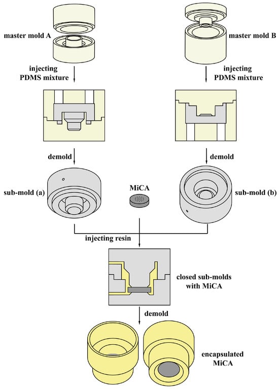
Figure 1.
Schematic diagram of the MiCA packaging process.
We also performed a series of comparative experiments to explore the effect of the mass of centrifugal force and the height of the oil phase on the radius of the microdroplets. As a demonstration of the feasibility of the proposed device in the field of material engineering, we used it to prepare fluorescent hydrogel microspheres. Furthermore, we performed a droplet digital polymerase chain reaction (ddPCR) experiment to validate the biocompatibility of the emulsion system.
2. Materials and Methods
2.1. The Fabrication Procedure of the Nested Structure
The general fabrication procedure of the nested structure is shown in Figure 1. We designed a delicate nested injection mold structure with a protrusion, which fits into the 200 μL PCR tube orifice well, and a MiCA inlay that does not compromise usability.
Figure 2 provides a more detailed illustration of the injection mold structures. First, we used 3D drawing software (Autodesk Fusion, Fusion 2.0.18460 x86_64) to design two sets of master molds based on feedback from subsequent injection molding tests. Then, we printed them out using a 3D printer (MAKEX, Ningbo, China) with the material Polyethylene Terephthalate Glycol (PETG) (EASTMAN, Kingsport, TN, USA). Then, two parts of each set of master molds were joined and positioned vertically on a bench with the channel facing up. Two sub-molds (a and b) were obtained by carefully injecting a degassed PDMS (RTV615, GE) 10:1 (w/w) mixture (Figure 2A,B) into the cavities of each set of coupled master molds through the injection holes with a 10 mL syringe. The PDMS mixture was subjected to vacuum degassing to remove bubbles that could impair the structure’s strength and stability.
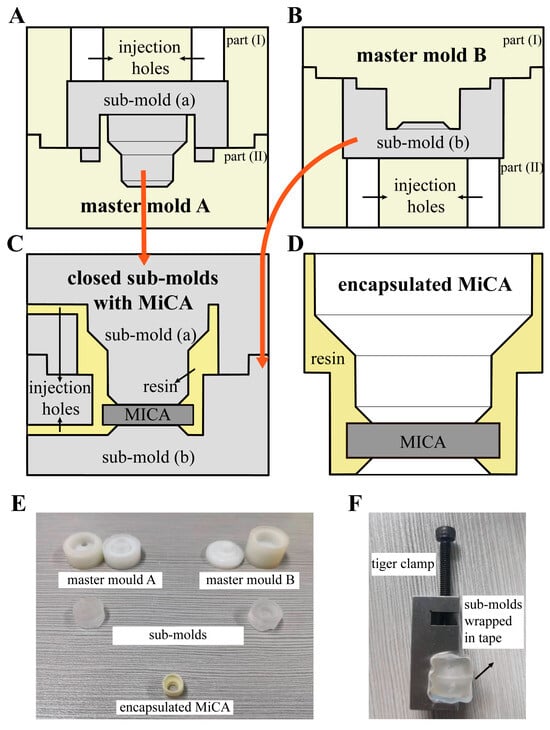
Figure 2.
Structure of injection molds. The orange arrows indicate that the gray parts in (A,B) are the molds in (C). (A) A sectional view of the structure of the master mold A. The desired sub-mold (a) was obtained by injecting the PDMS mixture through the injection holes on master mold A; (B) A sectional view of the structure of the master mold B. The desired sub-mold (b) was obtained by injecting the PDMS mixture through the injection holes on master mold B; (C) A sectional view of the structure of the closed sub-molds with MiCA. The encapsulated MiCA with a nested structure was obtained by integrating two sub-molds and injecting resin through the injection holes on the side; (D) A sectional view of the structure of the encapsulated MiCA in a nested structure; (E) Physical picture of the master molds, sub-molds, and the encapsulated MiCA with a nested structure; (F) Physical picture of the integrated sub-molds tightened by the tiger clamp.
The master molds were then removed to expose the desired PDMS sub-molds after incubation at 80 °C for 1 h.
Sub-mold (a) and sub-mold (b) correspond to one another, creating a cavity upon closure to accommodate the MiCA inlay, resulting in the formation of the nested structure as depicted in Figure 2C. Specifically, after positioning the MiCA at the center of sub-mold (b)’s groove using tweezers, we vertically pressed sub-mold (a) onto sub-mold (b). Consequently, the MiCA was compressed in the center of the nest structure by the two sub-molds (Figure 2C). Subsequently, the joined sub-molds were sealed using tape and clamped tight with linesman pliers (Figure 2F) to form a cavity inside that would be the shape of the designed nested micro structure. A 120 μL volume of liquid model glue (polyurethane resin, curing agent, 1:1 ratio) was introduced into the cavity through two 0.75 mm holes punched at the side of two sub-molds, hardening within the nest structure to encapsulate the MiCA following a room temperature cure for 20 min (Figure 2D).
To obtain microdroplets with higher quality, the nested structure device was rinsed with ethanol and ultrapure water and then soaked in a hydrophobic reagent (MesoBioSystem, Wuhan, China) for 5 min before sonication for 15 min. Then, it was vacuumed and dried for 10 min in preparation for subsequent use.
2.2. Generation of the Monodisperse Droplets
Figure 3A–G depict the operation process for generating monodisperse droplets. To generate stable water-in-oil droplets, phosphate-buffered saline (PBS) served as the dispersed phase while isopropyl palmitate with 7% (v/v) Cetyl polyethylene glycol/Poly propylene glycol-10/1 Dimethicone (ABIL EM180) (Evonik Industries AG, Essen, Germany) comprised the continuous phase (Figure 3B). First, the continuous phase was introduced into a 200 μL centrifuge tube and gently centrifuged to eliminate any air bubbles. Next, the encapsulated MiCA structure was inserted into the centrifuge tube orifice (Figure 3B). The dispersed phase was then pipetted into the MiCA structure. Centrifugation was conducted to generate the droplets. This process was carried out using a benchtop centrifuge (Eppendorf, Hamburg, Germany) for 10 min. To optimize the conditions of droplet generation, centrifugal force ranging from 3000× g to 13,000× g and continuous-phase volume ranging from 50 μL to 170 μL were tested. Observation and imaging of the generated droplets occurred through an inverted microscope (Ti2-E, Nikon, Tokyo, Japan). Measurements and analyses of the microdroplets’ diameters were performed using Image J (version 1.54d) software.
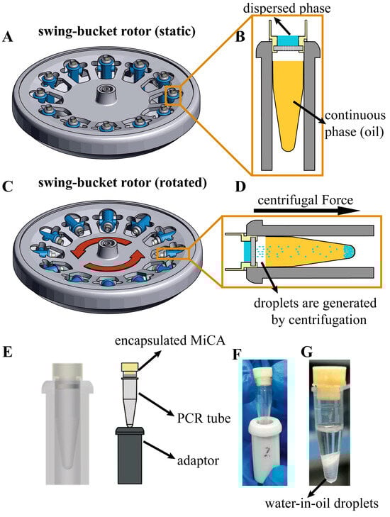
Figure 3.
Microdroplet generation with the encapsulated MiCA in our nested structure by centrifugation. (A) Encapsulated MiCA in the nested structure is placed in a PCR tube and swing-bucket rotor before centrifugation (static); (B) Enlarged view of the encapsulated MiCA in the nested structure placed in a PCR tube before centrifugation. The blue one above is the dispersed phase, and the orange one below is the continuous phase (oil); (C) The encapsulated MiCA in the nested structure is placed in a PCR tube and swing-bucket rotor during centrifugation (rotating); (D) Enlarged view of the encapsulated MiCA in the nested structure placed in a PCR tube during centrifugation. In the direction of centrifugal force, the dispersed phase breaks up into droplets and enters into the continuous phase to form stable water-in-oil droplets; (E) The perspective of the installation (left) and the structure of the device (right); (F) A physical picture of the installed device; (G) A physical picture of water-in-oil droplets produced after centrifugation.
Table 1 summarizes the operating temperature, fluid viscosity, and density of the materials we used for the nested structures to fabricate and generate the microdroplets.

Table 1.
Properties of the materials that are used in each step for fabricating the nested structures, and generating microdroplets.
2.3. Generation of the Fluorescent Microspheres
To confirm the chemical compatibility of our method, fluorescent microspheres were generated. The preparation of fluorescent hydrogel microspheres entails the formation of water-in-oil fluorescent droplets, which can be polymerized to yield stable fluorescent solids for extended preservation.
Isopropyl palmitate with 7% (v/v) EM180 served as the continuous phase. The dispersed phase was prepared by mixing 800 μL PBS buffer with 30% (v/v) polyethylene glycol diacrylate (PEGDA) (Sigama-Aldrich Corporation, St. Louis, MO, USA), 200 μL of PBS buffer with 20% (v/v) 2-hydroxy-2-methylpropiophenone (20% v/v) (TCI, Tokyo, Japan), and 20 μL of a water-soluble fluorescent substance (green fluorescent protein) (Sigama, Germany). The mixture was subsequently shaken gently for 5 min at room temperature, and a 20 μL aliquot was used for droplet generation. To obtain the proper size of droplets for microsphere curing, the centrifugal force was set at 11,000 and 15,000× g while the continuous phase was 150 μL. The microsphere curing step was the same as that previously reported [37]. Briefly, after centrifugation, the microdroplets in the centrifuge tube were gently transferred to a 24-well cell culture plate (SPL) and irradiated under ultraviolet for 30 s in darkness for polymerization. The generated PEGDA fluorescent hydrogel microspheres were subsequently rinsed twice with cyclohexane, anhydrous ethanol, and ultrapure water, followed by incubation at 50 °C overnight. The generated microspheres underwent observation and imaging under a spinning disk confocal microscope (SpinSR, Olympus, Tokyo, Japan) for fluorescence detection and 3D imaging and were subsequently analyzed with Image J software.
2.4. Droplet Digital Polymerase Chain Reaction(ddPCR)
To verify the feasibility and biocompatibility of our method, ddPCR was performed with the method previously reported [10]. In detail, the human genomic cDNA with the glyceraldehyde-3-phosphate dehydrogenase (GAPDH) gene was extracted from Hela cells and serially diluted as the PCR templates. A 10 μL amount of the PCR reaction mix consisted of 5 μL of TaqMan® Fast Advanced Master Mix (2×, Thermo Fisher Scientific Inc., Waltham, MA, USA), 0.5 μL of TaqMan® Gene Expression Assay (FAM dye) mix (20×) (GAPDH gene, Hs02758991_g1, Thermo Fisher Scientific Inc., Waltham, MA, USA), 1 μL of the template solution, and 4 μL of RNase-free water (Takara Bio. Inc., San Jose, CA, USA). Droplets were generated by centrifugation at 7000× g for 10 min with 150 μL of continuous phase.
To minimize potential contamination that could affect the final fluorescence results, a pre-treatment of the droplet generator was conducted prior to mixing the PCR raw droplets. The device was first subjected to ultrasonic cleaning for 20 min, followed by a soak in anhydrous ethanol for 5 min, and subsequently transferred to a Petri dish using tweezers. A vacuum-assisted method was then employed to remove moisture from the device. Following device preparation, the PCR tube was placed into the PCR machine to amplify the digital PCR sample. The PCR thermal cycling protocols were set as 40 two-step cycles (3 s at 95 °C and 30 s at 60 °C) with the initial UNG incubation step (120 s at 50 °C) and polymerase activation step (120 s at 95 °C) ahead. The entire process was completed within 45 min. PCR results were observed and photographed under an inverted fluorescence microscope.
3. Results and Discussion
3.1. Packaging of MiCA
Microfluidic devices enable fluid manipulation on a microscopic scale and are extensively used in biological and chemical analyses, point-of-care diagnostics, and drug delivery systems [16]. These applications typically necessitate the fabrication of channels and chambers with a width of merely a few micrometers, achievable through the precision afforded by microinjection molding. Polydimethylsiloxane (PDMS) deserves particular attention as a material extensively used in microinjection molding. Owing to its exceptional properties, such as optical transparency, biocompatibility, low toxicity, and cost-effectiveness, PDMS has become a standard in the production of microfluidic devices and other microcomponents [38]. The material we used to encapsulate MiCA was polyurethane (PU) resin, also widely known as AB water, which is the mainstream material for handwork. This material is cost-effective, is priced at less than one-third of casting resin, exhibits a yellow and dark hue, and is characterized by its brittleness and virtually nonexistent elasticity. Liquid A and liquid B can be solidified in 10–20 min after mixing, which is convenient for laboratory operation.
The MiCA packaging process necessitates two distinct sets of molds. The fabrication of sub-molds was completed by two sets of master molds, which were directly produced via 3D printing technology. By altering the parameters of the parent mold, the sub-molds can be changed indirectly to achieve the desired nested shape. The sub-molds were made of a mixture of polydimethylsiloxane (PDMS) and a curing agent, a material commonly used in the preparation of microfluidic chips, which has better light transmission, a certain degree of elasticity, and a low cost. The sub-molds employed for encapsulating MiCA must exhibit flexibility to avoid damaging the microchannel array plate due to excessive pressure and ensure a hermetic seal of its upper and lower surfaces. As the PDMS mixture is easy to process, we can punch the desired holes on demand using a hole punch. Our design used a 0.75 mm hole puncher to punch one hole in each of the two sub-molds. The 0.75 mm direct hole facilitates the insertion of the tip of the associated volume. After the two sub-molds were integrated, one hole was used to inject the injection molding material, and another hole was used to discharge the air, balance the air pressure in the mold cavity, and facilitate the injection of the injection molding material. Simultaneously, the overflow of the injected material from the other hole could be used as a signal for the end of the injection molding operation, making it easy to preserve the material. When they were pressed up and down together, the inner cavity formed a shape around the nested structure. There was a gap between the two sub-molds so that MiCA could fit in and get stuck. MiCA packaging material is a mixture of polyurethane resin and curing agent, which is quickly cured in air after mixing, reducing the time required for experiments. At the same time, the material is inexpensive, which can reduce the cost of experiments.
3.2. Formula Derivation
Figure 4A shows a diagram of droplets generated by MiCA. In the first step, the dispersed phase is driven by centrifugal force to pass the through-hole of MiCA. In the second step, the dispersed phase accumulates continuously on the surface of the other side of the MiCA, forming blisters along the edge of the through-hole. In the third step, the droplets form and fall off.
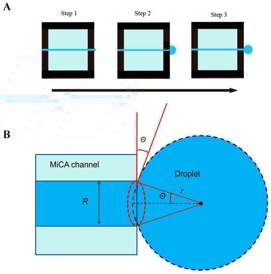
Figure 4.
Diagram of droplet formation under centrifugal drive.
Based on Figure 4B, as the centrifugal force and interfacial tension applied to the droplet at the moment of separation are equal, so
where F is the centrifugal force, and m is the mass of a droplet at the moment of separation.
where R is the radius of one MiCA channel, is the surface tension coefficient, and it is temperature-dependent. The higher the temperature, the lower the surface tension coefficient. We calculated the mass of a droplet at the moment of separation. The formula for calculating the spherical crown product is as follows:
where V represents the volume of the droplet, and r represents the radius of the droplet at the moment of separation. θ is the contact angle of the solid–liquid–gas interface.
So, the mass of the head part of the droplet is
where represents the density of the water phase.
From Equations (1)–(4),
From Formula (5), it can be seen that the radius of the droplet sphere is proportional to the radius of the microchannel and the surface tension coefficient and is inversely proportional to the density of the dispersed-phase droplet and the centrifugal force acceleration.
3.3. Formation and Characterization of Droplets of Water-in-Oil in Centrifugal Production
To elucidate the droplet formation mechanism of the proposed device, we characterized the droplet formation process. We initially assessed droplet formation under varying centrifugal forces at the same height of the continuous phase. The results, presented in Figure 5A–F, indicate that droplets were formed using 20 μL of the dispersed phase and 150 μL of the continuous phase under centrifugal forces ranging from 3000× g to 13,000× g. Generally, the droplet diameter decreases as the centrifugal force increases. Figure 5A shows that at 3000× g of centrifugal force, the larger droplets were accompanied by several smaller droplets, resulting in size heterogeneity among the microdroplets. A potential reason for the formation of uneven droplets may be that under low centrifugal force, due to the small flow rate in the channel, the large droplets that accumulate at the edge of the channel are crushed out of some smaller droplets during the formation process. This heterogeneity diminishes with increased centrifugal force. We observed a considerable variation in droplet diameter between 3000× g and 7000× g (Figure 5G), with the trend stabilizing post 7000× g. This phenomenon may arise due to the significant impact of centrifugal forces ranging from 3000× g to 7000× g on droplet shedding; beyond a specific threshold, droplet detachment and formation occur more rapidly, with this effect stabilizing thereafter. Figure 5H illustrates the efficiency of droplet production as a function of centrifugal force. The droplet generation throughput is the result of a droplet generation device. The rotor of the centrifuge we used can support the operation of 12 centrifugal droplet generators at the same time (Figure 3C), so the droplet generation efficiency is expected to be increased by 12 times with adequate preparation.
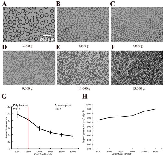
Figure 5.
The size and morphology of droplets generated under varied centrifugal forces. (A–F) The diameters of droplets generated at different centrifugal forces, with standard deviation (μm) and numbers (n) being statistically counted as 98.38 ± 9.51 (n = 61), 82.69 ± 3.64 (n = 180), 46.00 ± 4.91 (n = 352), 57.50 ± 5.54 μm (n = 363), 39.81 ± 4.41 μm (n = 498), 35.53 ± 5.27 μm (n = 571), respectively. Scale bars: 200 μm; (G) The linear relationship between the centrifugal forces and droplet diameters (mean ± SD, n > 60). (H) The relationship between the throughput produced by the droplets and the centrifugal force.
We subsequently examined the impact of differing continuous-phase volumes (height) on droplet formation under constant centrifugal force. Under a 20 μL dispersed phase and 9000× g centrifugal force, the continuous-phase volume was varied from 50 μL to 170 μL. The experiments were performed for each volume. The results are shown in Figure 6. This phenomenon could be attributed to the fact that changing the volume of the continuum phase essentially changes the distance the droplet can travel. (shown in Figure 3D). As shown in the figure, when the volume of the continuous phase was smaller than 110 μL, poly-dispersed droplets were generated, leading to heterogeneity in the droplets. Conversely, monodisperse droplets were obtained when the continuous-phase volume exceeded 110 μL, resulting in homogeneous droplets. Furthermore, it can be seen from the standard deviation in Figure 6 that the droplet diameter tended to stabilize with increasing liquid surface height. We consider this to be a change in the droplet homogeneity due to the change in the travel distances of the droplets within the PCR tube. Upon detachment from the channel and trajectory over a certain distance, the droplets enter the continuous phase and become water-in-oil droplets. The fragmentation and separation of droplets may be due to the surface tension within the continuous phase. The occurrence of partial coalescence among the fragmented droplets also impacted their uniformity.
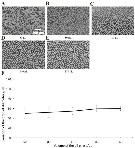
Figure 6.
The size and morphology of droplets generated under varied volumes of continuous phase. Panel (A–E) represent the droplets generated under different volumes of continuous phase (50 μL, 80 μL, 110 μL, 140 μL, and 170 μL, respectively). Scale bar is 200 µm; (F) The relationship between the variation of droplet size and the volumes of the continuous phase (mean ± SD, n > 260).
3.4. Generation and Characterization of Fluorescent Microspheres
We demonstrated the potential for biomaterial applications using our device to generate droplets. Our droplet generation device based on centrifugal force can produce a large quantity of water-in-oil droplets in a short time. We can create the droplets we want by rearranging the composition of the dispersed phase. PEGDA and fluorescent substances were added into the dispersed phase to form fluorescent droplets, which subsequently underwent UV-induced curing to form polymer microspheres. The underlying mechanism involves activated free radicals initiating photopolymerization by targeting the carbon–carbon double bonds in PEGDA’s acrylate groups, culminating in the formation of linear chains and cross-link networks [37]. Results from confocal laser scanning microscopy (CLSM) are depicted in Figure 7. Fluorescent microspheres were generated under centrifugal forces of 15,000× g and 11,000× g , with a dispersed-phase volume of 20 μL and a continuous-phase volume of 150 μL. As depicted in Figure 7A,B, the spheres exhibit a uniform and intense green fluorescence. In the 3D fluorescence image (Figure 7C), it is evident that the fluorescent material is uniformly distributed within the green sphere. Our device efficiently produces fluorescent hydrogel microspheres and boasts simple operation. Consequently, it is anticipated that the proposed device will see broad application in the synthesis of microbeads with various dispersed-phase compositions. This demonstrates its potential as a formidable tool in droplet material engineering.
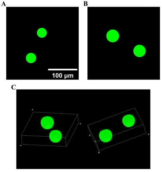
Figure 7.
Two- and three-dimensional images of hydrogel microspheres generated by our method. The scale bar is 100 µm. (A) Two-dimensional image of fluorescent microspheres obtained under centrifugal force of 15,000× g; (B) two-dimensional image of fluorescent microspheres obtained under centrifugal force of 11,000× g; (C) three-dimensional images of fluorescent microspheres obtained under centrifugal force of 11,000× g, indicating that the fluorescent material is uniformly dispersed in the whole microsphere.
3.5. Biocompatibility and Biological Application Potentials
To assess the biocompatibility of an emulsification system subjected to high-speed centrifugation and its application potential in biological reactions, ddPCR assays were performed within PCR tubes incorporating the system in question. Our methodology entailed centrifugation of a 15 μL PCR mix at a centrifugal force of 7000× g for 10 min, alongside a continuous-phase volume of 150 μL utilizing our specially designed centrifugal droplet generator. This process facilitates the in situ formation of droplets directly within the PCR tube, thereby enabling immediate amplification subsequent to the removal of the nested device and notably diminishing the risk of reagent contamination. Following amplification, droplets were transferred with precision using a pipette onto glass slides for further analysis. Extreme precision was requisite in this step to prevent potential droplet contamination and to avoid the merging of droplets. Figure 8 demonstrates marked fluorescence within droplets containing DNA templates, indicative of a positive test. The copy numbers per microliter of the target gene in the serially diluted solutions were calculated by counting the numbers of positive (Npositive) and total droplets (Ntotal) and corrected using a Poisson distribution by the following formula:
where V stands for the reaction volume (µL).
Gcopy = −ln(1 − Npositive/Ntotal)/V
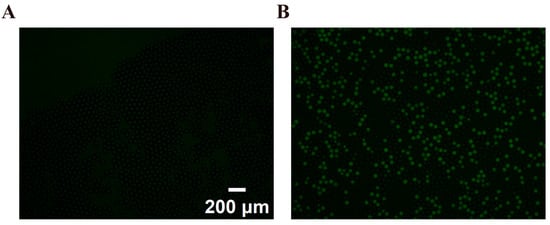
Figure 8.
Fluorescent image of droplets with (A) negative control; (B) 357.294 copies/μL.
Such fluorescence signals, emitted from the droplet post-PCR amplification, indicate successful DNA amplification, thus confirming the preservation of bioactivity of the critical biomolecule despite the centrifugation conditions applied. This verification underscores the effectiveness of the centrifugal approach in maintaining molecular integrity during ddPCR.
4. Conclusions
In this study, we developed a novel encapsulation method for MiCA via injection molding for application in centrifugal droplet generation. MiCA presents a unique cost advantage over other methods, including capillaries, for generating droplets within a PCR tube. The packaged injection molding technology we developed can encapsulate MiCA, which can greatly reduce the cost and simplify the experimental operation. We used encapsulated MiCA to produce droplets across various scales. To demonstrate the application of the device in materials engineering, we used the device to generate fluorescent microspheres. Our device based on centrifugal force for generating droplets is expected to be used to prepare cellular functional microbeads. Additionally, the fabrication process is straightforward, exhibiting broad application potential and value in laboratory and enterprise research. Furthermore, following the ddPCR experiments, it has been demonstrated that the surface-treated bioactivity of biomolecules remains substantially unaffected by the method based on centrifugal force, affirming the favorable biocompatibility and biological reaction potential of the emulsion system. However, optimization of the proposed injection-molded parts constitutes a focal point for future work. In the experiment, the centrifuge (Centrifuge 5417 R, Eppendorf, Germany) used in our droplet-generating device has a flux of 12 rotors, which can achieve the simultaneous operation of 12 droplet devices. By altering the model of the centrifuge, the droplet generation scale can be expanded further. For example, Centrifuge 5430 R (Eppendorf, Germany) incorporates a rotor with a flux of 24. Additional work, including but not limited to enhancing the existing nested structure, boosting encapsulation efficiency, and integrating the full device into microtubules, is required.
Author Contributions
J.L.: Writing—original draft, Investigation, Visualization, and Data curation. W.L.: Conceptualization, Methodology, Visualization, and Data curation. B.W.: Conceptualization and Methodology. W.B.: Writing—reviewing & editing, Visualization, and Data curation. M.L.: Writing—reviewing & editing. J.O.: Validation. Y.X.: Validation. S.W.: Validation and Software. Y.H.: Conceptualization, Resources, and Methodology. Y.F.: Writing—reviewing & editing, Formal analysis, and Supervision. Y.M.: Conceptualization, Resources, Supervision, Project administration and Funding acquisition. All authors have read and agreed to the published version of the manuscript.
Funding
This work was supported by The National Key R&D Program of China (2021YFC3300101), Shenzhen Fundamental Research Program (JCYJ20220531100803007, JSGG20201103153802007) and Open Fund Programs of Shenzhen Bay Laboratory (SZBL2020090501001).
Data Availability Statement
The data presented in this study are available on request from the corresponding author and the first author.
Acknowledgments
We thank Xiaoping Guo and her company Guangzhou SuGao Communication Equipment Co., Ltd. for their support of the material (MiCA) in the equipment manufacturing process.
Conflicts of Interest
The authors declare no conflicts of interest. The funders had no role in the design of the study; in the collection, analyses, or interpretation of data; in the writing of the manuscript; or in the decision to publish the results.
References
- Theberge, A.B.; Courtois, F.; Schaerli, Y.; Fischlechner, M.; Abell, C.; Hollfelder, F.; Huck, W.T.S. Microdroplets in microfluidics: An evolving platform for discoveries in chemistry and biology. Angew. Chem. Int. Ed. 2010, 49, 5846–5868. [Google Scholar] [CrossRef]
- Huebner, A.; Sharma, S.; Srisa-Art, M.; Hollfelder, F.; Edel, J.B.; Demello, A.J. Microdroplets: A sea of applications? Lab Chip 2008, 8, 1244–1254. [Google Scholar] [CrossRef]
- Schaerli, Y.; Hollfelder, F. The potential of microfluidic water-in-oil droplets in experimental biology. Mol. Biosyst. 2009, 5, 1392–1404. [Google Scholar] [CrossRef]
- Kintses, B.; van Vliet, L.D.; Devenish, S.R.A.; Hollfelder, F. Microfluidic droplets: New integrated workflows for biological experiments. Curr. Opin. Chem. Biol. 2010, 14, 548–555. [Google Scholar] [CrossRef]
- Seemann, R.; Brinkmann, M.; Pfohl, T.; Herminghaus, S. Droplet based microfluidics. Rep. Prog. Phys. 2011, 75, 016601. [Google Scholar] [CrossRef]
- Joensson, H.N.; Andersson Svahn, H. Droplet microfluidics—A tool for single-cell analysis. Angew. Chem. Int. Ed. 2012, 51, 12176–12192. [Google Scholar] [CrossRef]
- Jiang, Z.; Shi, H.; Tang, X.; Qin, J. Recent advances in droplet microfluidics for single-cell analysis. TrAC Trends Anal. Chem. 2023, 159, 116932. [Google Scholar] [CrossRef]
- Hindson, B.J.; Ness, K.D.; Masquelier, D.A.; Belgrader, P.; Heredia, N.J.; Makarewicz, A.J.; Bright, I.J.; Lucero, M.Y.; Hid-dessen, A.L.; Legler, T.C.; et al. High-throughput droplet digital PCR system for absolute quantitation of DNA copy number. Anal. Chem. 2011, 83, 8604–8610. [Google Scholar] [CrossRef] [PubMed]
- Miotke, L.; Lau, B.T.; Rumma, R.T.; Ji, H.P. High sensitivity detection and quantitation of DNA copy number and single nucleotide variants with single color droplet digital PCR. Anal. Chem. 2014, 86, 2618–2624. [Google Scholar] [CrossRef]
- Bu, W.; Li, W.; Li, J.; Ao, T.; Li, Z.; Wu, B.; Wu, S.; Kong, W.; Pan, T.; Ding, Y.; et al. A low-cost, programmable, and multi-functional droplet printing system for low copy number SARS-CoV-2 digital PCR determination. Sens. Actuators B Chem. 2021, 348, 130678. [Google Scholar] [CrossRef]
- Nisisako, T.; Torii, T. Microfluidic large-scale integration on a chip for mass production of monodisperse droplets and particles. Lab Chip 2008, 8, 287–293. [Google Scholar] [CrossRef]
- Ofner, A.; Moore, D.G.; Rühs, P.A.; Schwendimann, P.; Eggersdorfer, M.; Amstad, E.; Weitz, D.A.; Studart, A.R. High-throughput step emulsification for the production of functional materials using a glass microfluidic device. Macromol. Chem. Phys. 2017, 218, 1600472. [Google Scholar] [CrossRef]
- Li, W.; Greener, J.; Voicu, D.; Kumacheva, E. Multiple modular microfluidic (M3) reactors for the synthesis of polymer particles. Lab Chip 2009, 9, 2715–2721. [Google Scholar] [CrossRef]
- Giannitelli, S.M.; Limiti, E.; Mozetic, P.; Pinelli, F.; Han, X.; Abbruzzese, F.; Basoli, F.; Del Rio, D.; Scialla, S.; Rossi, F.; et al. Droplet-based microfluidic synthesis of nanogels for controlled drug delivery: Tailoring nanomaterial properties via pneumatically actuated flow-focusing junction. Nanoscale 2022, 14, 11415–11428. [Google Scholar] [CrossRef]
- Anna, S.L.; Bontoux, N.; Stone, H.A. Formation of dispersions using “flow focusing” in microchannels. Appl. Phys. Lett. 2003, 82, 364–366. [Google Scholar] [CrossRef]
- Zhou, C.; Yue, P.; Feng, J.J. Formation of simple and compound drops in microfluidic devices. Phys. Fluids 2006, 18, 092105. [Google Scholar] [CrossRef]
- Yobas, L.; Martens, S.; Ong, W.L.; Ranganathan, N. High-performance flow-focusing geometry for spontaneous generation of monodispersed droplets. Lab Chip 2006, 6, 1073–1079. [Google Scholar] [CrossRef] [PubMed]
- Chen, Z.; Liao, P.; Zhang, F.; Jiang, M.; Zhu, Y.; Huang, Y. Centrifugal micro-channel array droplet generation for highly parallel digital PCR. Lab Chip 2017, 17, 235–240. [Google Scholar] [CrossRef] [PubMed]
- Cui, Y.; Li, Y.; Wang, K.; Deng, J.; Luo, G. High-throughput preparation of uniform tiny droplets in multiple capillaries embedded stepwise microchannels. J. Flow Chem. 2020, 10, 271–282. [Google Scholar] [CrossRef]
- Gelin, P.; Bihi, I.; Ziemecka, I.; Thienpont, B.; Christiaens, J.; Hellemans, K.; Maes, D.; De Malsche, W. Microfluidic device for high-throughput production of monodisperse droplets. Ind. Eng. Chem. Res. 2020, 59, 12784–12791. [Google Scholar] [CrossRef]
- Shin, D.C.; Morimoto, Y.; Sawayama, J.; Miura, S.; Takeuchi, S. Centrifuge-based step emulsification device for simple and fast generation of monodisperse picoliter droplets. Sens. Actuators B Chem. 2019, 301, 127164. [Google Scholar] [CrossRef]
- Haeberle, S.; Zengerle, R.; Ducrée, J. Centrifugal generation and manipulation of droplet emulsions. Microfluid. Nanofluidics 2007, 3, 65–75. [Google Scholar] [CrossRef]
- Gorkin, R.; Park, J.; Siegrist, J.; Amasia, M.; Lee, B.S.; Park, J.-M.; Kim, J.; Kim, H.; Madou, M.; Cho, Y.-K. Centrifugal microfluidics for biomedical applications. Lab Chip 2010, 10, 1758–1773. [Google Scholar] [CrossRef]
- Azimi-Boulali, J.; Madadelahi, M.; Madou, M.J.; Martinez-Chapa, S.O. Droplet and particle generation on centrifugal microfluidic platforms: A review. Micromachines 2020, 11, 603. [Google Scholar] [CrossRef]
- Schulz, M.; Probst, S.; Calabrese, S.; Homann, A.R.; Borst, N.; Weiss, M.; von Stetten, F.; Zengerle, R.; Paust, N. Versatile tool for droplet generation in standard reaction tubes by centrifugal step emulsification. Molecules 2020, 25, 1914. [Google Scholar] [CrossRef] [PubMed]
- Tang, M.; Wang, G.; Kong, S.K.; Ho, H.-P. A review of biomedical centrifugal microfluidic platforms. Micromachines 2016, 7, 26. [Google Scholar] [CrossRef] [PubMed]
- Shi, Y.; Ye, P.; Yang, K.; Meng, J.; Guo, J.; Pan, Z.; Zhao, W.; Guo, J. Application of centrifugal microfluidics in immunoassay, biochemical analysis and molecular diagnosis. Analyst 2021, 146, 5800–5821. [Google Scholar] [CrossRef] [PubMed]
- Ahmed, N.; Sukovich, D.; Abate, A.R. Operation of droplet-microfluidic devices with a lab centrifuge. Micromachines 2016, 7, 161. [Google Scholar] [CrossRef]
- Yang, C.; Yin, X.H.; Cheng, G.M. Microinjection molding of microsystem components: New aspects in improving performance. J. Micromech. Microeng. 2013, 23, 093001. [Google Scholar] [CrossRef]
- Czepiel, M.; Bańkosz, M.; Sobczak-Kupiec, A. Advanced Injection Molding Methods. Materials 2023, 16, 5802. [Google Scholar] [CrossRef] [PubMed]
- Zhang, L.; Chen, Y.; Tan, J.; Feng, S.; Xie, Y.; Li, L. Performance Enhancement of PLA-Based Blend Microneedle Arrays through Shish-Kebab Structuring Strategy in Microinjection Molding. Polymers 2023, 15, 2234. [Google Scholar] [CrossRef]
- Shen, Y.K.; Chang, C.Y.; Shen, Y.S.; Hsu, S.-C.; Wu, M.-W. Analysis for microstructure of microlens arrays on micro-injection molding by numerical simulation. Int. Commun. Heat Mass Transf. 2008, 35, 723–727. [Google Scholar] [CrossRef]
- Su, Q.; Zhang, N.; Gilchrist, M.D. The use of variotherm systems for microinjection molding. J. Appl. Polym. Sci. 2016, 133. [Google Scholar] [CrossRef]
- Giboz, J.; Copponnex, T.; Mélé, P. Microinjection molding of thermoplastic polymers: A review. J. Micromech. Microeng. 2007, 17, R96. [Google Scholar] [CrossRef]
- Fu, H.; Xu, H.; Liu, Y.; Yang, Z.; Kormakov, S.; Wu, D.; Sun, J. Overview of injection molding technology for processing polymers and their composites. ES Mater. Manuf. 2020, 8, 3–23. [Google Scholar] [CrossRef]
- Wang, Z.; Zhang, F.; Wang, Z.; Liu, Y.; Fu, X.; Jin, A.; Yung, B.C.; Chen, W.; Fan, J.; Yang, X.; et al. Hierarchical assembly of bioactive amphiphilic molecule pairs into supramolecular nanofibril self-supportive scaffolds for stem cell differentiation. J. Am. Chem. Soc. 2016, 138, 15027–15034. [Google Scholar] [CrossRef] [PubMed]
- Kong, W.; Feng, H.; Qian, X.; Chen, Y.; Deng, M.; Zhang, P.; Li, W.; Bu, W.; Xu, W.; Jin, W.; et al. Facile and scalable generation of fluorescent microspheres using a microfluidic electrojetting device. Sens. Actuators B Chem. 2023, 378, 133106. [Google Scholar] [CrossRef]
- Raj, M.K.; Chakraborty, S. PDMS microfluidics: A mini review. J. Appl. Polym. Sci. 2020, 137, 48958. [Google Scholar] [CrossRef]
Disclaimer/Publisher’s Note: The statements, opinions and data contained in all publications are solely those of the individual author(s) and contributor(s) and not of MDPI and/or the editor(s). MDPI and/or the editor(s) disclaim responsibility for any injury to people or property resulting from any ideas, methods, instructions or products referred to in the content. |
© 2024 by the authors. Licensee MDPI, Basel, Switzerland. This article is an open access article distributed under the terms and conditions of the Creative Commons Attribution (CC BY) license (https://creativecommons.org/licenses/by/4.0/).