
Effect of Mold Flow Channel Parameters on Gas-Assisted Extrusion of Medical Microtubules

1
Department of Mechanical Engineering, College of Advanced Manufacturing, Nanchang University, Nanchang 330031, China
2
Jiangxi Province Key Laboratory of Precision Drive & Control, Nanchang Institute of Technology, Nanchang 330099, China
*
Author to whom correspondence should be addressed.
Processes 2023, 11(7), 1973; https://doi.org/10.3390/pr11071973
Submission received: 2 June 2023
/
Revised: 21 June 2023
/
Accepted: 27 June 2023
/
Published: 29 June 2023
(This article belongs to the Special Issue Research on Polymer Processing Technology)
Abstract
:Due to the complexity of mold flow channel parameters, they have a significant impact on medical microtubule forming quality during the gas-assisted extrusion process. In this paper, the influence mechanism of mold flow channel parameters on medical microtubule forming quality is investigated. First, the multiphase flow model of the medical microtubule gas-assisted extrusion process is established. Then, the numerical solution of medical microtubule extrusion is presented based on Polyflow finite element software. Further, the medical microtubule size, morphology, velocity, pressure, and first normal stress difference under different mold flow channel parameters are compared and analyzed. Finally, the experimental platform for gas-assisted extrusion is built, and the correctness of the numerical simulation is verified by the extrusion experiment. The simulation and experimental results show that under the 15–5 condition, the inner radius, outer radius, and wall thickness of the microtubule are closer to ideal values, and the forming quality is better than other parameters. As the ratio of the gas-assisted to non-gas-assisted sections increases, the gas effect becomes more intense, and the shrinkage of the microtube increases. In the gas-assisted section, the wall thickness and outer radius of the microtubes increase first and then decrease, and they stay the same near the exit section. This reveals that gas-assisted forming technology can effectively eliminate extrusion swelling.
1. Introduction
The medical microtubule has excellent properties, such as good flexibility, biocompatibility, and low friction factors [1,2,3]. It is widely used in interventional surgery, in vivo drug delivery, body fluid drainage, and other medical clinical fields [4,5]. The medical microtubule is prone to defects during traditional extrusion molding preparation, such as extrusion deformation, stretching thinning, and surface roughness [6,7,8,9]. These defects seriously affect the performance and safety of medical microtubules. To improve the forming quality of medical microtubules and effectively solve extrusion deformation and other problems, a gas-assisted extrusion technology is adopted to prepare medical microtubules [10]. In the gas-assisted extrusion process, the extrusion mold parameters directly affect the medical microtubule forming quality [11,12,13,14]. In traditional mold parameter design, empirical methods are often used and cannot reveal the inherent laws between forming quality and mold parameters. The combination of numerical simulation and experimental verification methods can clarify the impact of mold parameters on forming quality and optimize forming parameters and then overcome the shortcomings of traditional design methods, improve medical microtubule forming quality, and reduce the waste rate.
In the process of gas-assisted extrusion, process parameters seriously affect product forming quality. To clarify the inherent mechanism of microtube gas-assisted extrusion molding, the numerical simulation method was used to study the gas-assisted extrusion technology. Ren et al. [15], to solve the problems of extrusion expansion and melt rupture during microtubule forming, studied the double-layer assisted extrusion technology based on the finite element numerical simulation method and then compared the melt velocity field and stress field under different gas flows. Finally, the internal mechanism of microtubule deformation under different gas flow rates was clarified, and it was found that the normal stress caused by assist gas is the main factor leading to microtubule deformation. To obtain the inlet pressure and form a stable gas assist layer during the gas-assisted extrusion, Liu et al. [16] combined numerical simulation and experimental verification methods to analyze the rheological properties of the melt and the quality of microtube forming under different gas pressures. Finally, they clarified the influence of gas pressure on microtube extrusion molding and the formation mechanism of the assist gas layer. Luo et al. [17] designed a new mold with an independent built-in air duct to address the periodic melt rupture. The effectiveness of the mold was verified through numerical simulation and experiments. Finally, the flow parameters for forced exhaust were clarified, successfully eliminating the problem. Bin Liu et al. [18] aimed to clarify the interaction between the inner and outer gas layers in gas-assisted extrusion, and obtain the internal stress distribution mechanism. They established a geometric modeling of the double-layer assisted extrusion inside and outside the microtubule. Then, through numerical simulation and experiments, the viscoelasticity of melt in the mold was analyzed. Finally, the influence law of pressure difference between the inner and outer cushion on microtubule forming was obtained. Due to the high precision requirements for microtubule size, previous research on gas-assisted extrusion technology has mostly focused on the influence of gas flow rate, pressure, and other parameters on microtubule forming quality. However, there has been no research on the changes in mold flow channel parameters, and there is a lack of mechanisms for the influence of the flow channel parameters on melt rheological properties and microtubule forming quality. It restricts the development of medical microtubules and their forming technology.
To study the mechanism of the influence of mold flow channel parameters change on melt rheological properties, and to obtain medical microtubule forming quality laws based on fluid compression theory, a physical and mathematical model for the double gas-assisted extrusion of medical microtubules with different channel parameters was constructed, and fluid boundary condition parameters were established. Then, we analyzed the interaction and stress distribution between gas and melt under different parameters, comprehensively analyzed the medical microtubule size, quality, velocity field distribution, and stress distribution, and analyzed the changes in inner diameter, outer diameter, and wall thickness. Finally, a medical microtubule double gas-assisted extrusion experiment was conducted, combining size analysis and morphology analysis to verify the correctness of the numerical simulation.
This paper is structured as follows: The Section 1 mainly describes the advantages and disadvantages of medical microtubules, and expounds the research status and shortcomings of medical microtubule processing technology. The Section 2 constructs medical microtubule gas-assisted extrusion physical and mathematical models, and clarifies the physical parameters and boundary conditions. The Section 3 provides a detailed analysis of medical microtubule size indicators and flow field distribution under different channel parameters. In the Section 4, experimental equipment is built for experiments to analyze microtube forming quality and verify the numerical simulation results. The Section 5 gives conclusions.
2. Medical Microtubule Gas-Assisted Extrusion Model and Numerical Method
2.1. Physical Models
Based on compressible gas and incompressible melt, medical microtubule double gas-assisted extrusion physical models are established, and numerical simulations are conducted to analyze melt viscoelastic inside the mold. Figure 1 shows the medical microtubule double gas-assisted extrusion physical models. The distribution of the melt and assist gas in the mold is shown in Figure 1a. The inner and outer assist gas form a stable buffer layer between the melt and mold, and convert the melt extrusion from the non-slip adhesive extrusion to fully slip non-adhesive extrusion. Figure 1b is the schematic diagram of medical microtube double gas-assisted extrusion. After passing through the splitter cone, the melt passes through the non-gas-assisted shaping section, and is then formed in the gas-assisted shaping section. Due to the medical microtubule’s axisymmetric structure, to save calculation memory consumption and improve finite element calculation efficiency, a simplified 2D model is adopted, and medical microtubule extrusion numerical simulation calculation is carried out based on the 2D 1/2 axisymmetric method. As shown in Figure 1c, Sd1 is the melt area of the non-gas-assisted shaping section. Sd2 is the melt area of the gas-assisted shaping section. Sd3 is the melt area outside the mold. Sd4 and Sd5 are the assist gas layers. MN is the centerline of the medical microtubule. BE and FJ represent the inner wall surface of the mold. AC and CG represent the outer wall surface of the spindle. DH and EI represent the interface. In the simulation and experimental study of medical microtubule gas-assisted extrusion molding, the wall thickness of the microtubule is 0.5 mm, i.e., KL = 0.5 mm. The inner diameter of the microtubule is 1 mm, which means the distance between AK and MN is 1 mm. The outer diameter is 1.5 mm, which means the distance from BL to MN is 1.5 mm. The thickness of the assist gas layers is 0.2 mm, and the length of the outside the mold is 10 mm, i.e., IL = 10 mm. To study the influence of mold flow channel parameters on medical microtubule forming quality, the mold internal shaping section parameters are changed, that is, to study the size factors between the non-gas-assisted shaping section and the gas-assisted shaping section on melt rheological properties and their impact on medical microtubule forming quality. We set the non-gas-assisted shaping section (I) and gas-assisted shaping section (II) as I: II with 20 mm: 0 mm, 15 mm: 5 mm, 10 mm: 10 mm, 5 mm: 15 mm, and 0 mm: 20 mm, respectively. When the non-gas-assisted shaping section is set to 20 mm, it is a traditional extrusion model. We conducted simulation and experimental research on five models to clarify the internal mechanism of the influence of mold flow channel parameters on medical microtubule formation. To improve the accuracy of numerical simulation calculations, the meshes of the melt inlet, melt outlet, and interface between fluids at each stage were densified, as shown in Figure 1d.
2.2. Mathematical Models
Using numerical simulation methods to study the influence of process parameters on medical microtubule gas-assisted extrusion quality, due to the inability to reflect all conditions in the experiment, the following assumptions are made for the finite element simulation based on flow characteristics of melt and assist gas in the mold: Polymer melt as incompressible non-Newtonian fluid. Due to the gas viscosity being small, and the flow is not affected by the shear rate, so the assist gas is regarded as a compressible Newtonian fluid. Due to the high viscoelasticity of polymer melt and the small air mass, the influence of the inertia force and gravity of polymer melt and assist gas on its flow performance is ignored. The relative slip between gas, wall, and melt, as well as the permeation effect of assist gas molecules on polymer melt, are not considered [19]. The control equations of melt and gas are as follows.
Continuity equation:
Momentum equation:
Energy equation:
where ρk represents density. represents velocity vector. ∇ is a Hamiltonian operator. k = Ⅰ, Ⅱ, represent polymer melt and assist gas, respectively. Pk represents pressure. τk is stress tensor. Tk represents temperature. Cp is the constant pressure specific heat capacity. is the thermal conductivity flux. represents viscous dissipation term.
Since the polymer melt is a viscoelastic fluid, the Phan Thien Tanner (PTT) model [20] can well characterize polymer melt shear thinning characteristics and the first normal stress difference under large shear rate conditions, and can better reflect polymer melt flow characteristics. Therefore, the PTT model is used to describe the flow of the melt. The exponential constitutive equation is:
where ηr is the viscosity ratio of the polymer melt, ηr = η2/η, η2 represents the viscosity corresponding to the pure viscous part of the deviatoric stress tensor, η is the total viscosity of the polymer melt. λ represents the relaxation time of polymer melt. ε is the material parameter related to the tensile properties of polymer melts. ξ is the melt material parameter related to the shear viscosity. and represent the upper and lower material derivatives of τ1, the partial stress tensor, respectively. D is the deformation rate tensor of the polymer melt.
In the simplified model, the assist gas is regarded as a compressible Newtonian fluid, and the gas density changes with the change of compressibility. To ensure the closed-loop nature in the assist gas numerical solution equations, the gas state equation is introduced.
where P represents gas pressure. ρ represents gas density. T represents gas temperature. R represents gas constant, and R = 8.314 J/(mol·K).
2.3. Boundary Conditions
To ensure the numerical simulation, it is necessary to set model boundary conditions. The melt is extruded along the y-axis, and radial motion is along the x-axis. fx and fy represent the normal stress and tangential stress, respectively, and Vx and Vy represent the normal phase velocity and tangential velocity, respectively. According to the medical microtube gas-assisted extrusion model constructed in Figure 1, the boundary conditions are set as in Table 1.
- (1)
- Inlet boundary: AB is the melt inlet boundary. CD and EF are the gas inlet boundary. Assuming that the melt has fully developed into the non-Newtonian viscoelastic laminar flow after passing through the mold compression section and entering the shaping section, and the melt inlet boundary satisfies the conditions Vx = 0, the inlet boundary is set as the flow inlet boundary, and the inlet flow velocity is 2.0 × 10⁻⁸ m3/s, and the boundary temperature is set to 463 K. The gas inlet boundary is set as the pressure inlet boundary. According to the study of inner and outer gas pressure by Liu [18], the inner assist gas pressure is set to 7500 Pa, the outer assist gas pressure is set to 6500 Pa, and the temperature is set to 463 K.
- (2)
- Wall boundary: In the mold shaping section, there are two types of wall boundaries: melt–mold wall boundary and gas–mold wall boundary. In the non-gas-assisted shaping section, AD and BE gas are the melt–mold wall boundary, and the wall conditions meet the non-slip boundary conditions, Vx = 0, Vy = 0. For the gas-assisted shaping section, CG is the gas–mold wall surface, the wall conditions meet the complete slip boundary conditions, the Navier equation is used to set the slip boundary, and the slip coefficient is set to 0. All wall boundaries’ temperatures are set to 463 K.
- (3)
- Gas–liquid interface boundary: DH and EI are the interface boundaries between assist gas and polymer melt. Ignoring the influence of relative slip and surface tension between gas and polymer melt on fluid flow, the stress on both sides of the interface remains balanced, and melt and gas do not penetrate the interface.
- (4)
- Free surface boundary: HK and IL are the free surface boundaries of melt, and all satisfy the dynamic boundary conditions fx = 0, fy = 0, and Vx = 0.
- (5)
- Outlet boundary: KL is the outlet boundary of melt. GH and IJ are the inner and outer assist gas outlet boundaries, respectively.
2.4. Physical Property Parameters of Numerical Simulation
Polypropylene (PP) has excellent properties, such as high toughness, high strength, and high permeability. It is the main raw material for preparing medical microtubes. Therefore, this article uses PP for experimental analysis. The physical parameters of polymers and gases used in the numerical simulation are shown in Table 2 [21].
2.5. Software and Numerical Methods
In the numerical simulation of medical microtubes gas-assisted extrusion, ANSYS Geometry and ANSYS Mesh are used to establish the geometric and finite element models. ANSYS POLYFLOW is used to establish computational tasks and perform numerical solutions, and ANSYS CFD-POST is used for post-processing analysis. To facilitate the numerical solution, Elastic viscous splitstress (EVSS) and Streamline upwinding (SU) were used to solve the equations. In order to converge the equation solution, the Evolution method is used to set the inlet flow rate and relaxation time of the melt, and the Spine method is used to reset the meshes of the free surface.
3. Numerical Simulation Results and Analysis
Medical microtubule forming quality is closely related to the melt flow state in the mold. The geometric quality of microtube extrusion under different mold channel parameters was analyzed, and the distribution of the axial velocity field, radial velocity field, pressure field, and first normal stress difference of the melt was combined to analyze the mechanism of how mold channel parameters impact medical microtube gas-assisted forming quality.
3.1. Analysis of Extrusion Quality Analysis
To clarify the effect of mold channel parameters on medical microtubule forming quality, the inner radius, outer radius, wall thickness, and the shrinkage rates of medical microtubules under different channel parameters were analyzed, as shown in Figure 2. The length change of the non-gas-assisted shaping section and gas-assisted shaping section in the mold has a great influence on microtubule forming size. As shown in Figure 2a,b, the melt size has the same trend along the extrusion direction. In the process of the melt from the non-gas-assisted shaping section to the gas-assisted shaping section, the inner radius decreases at first and then increases, while the outer radius increases at first and then decreases, and does not change after the melt close to the exit of mold. Mainly due to the existence of the gas channel, the outer radius increases when the melt enters the gas-assisted shaping section, and the assist gas has the compressibility and elastic energy storage and normal stress effect of melt. These cause melt swelling. Then, due to the auxiliary gas, under the action of internal and external gas pressure, the melt expansion is gradually eliminated and reaches a stable state. The medical microtubule thickness increases first and then decreases, and stabilizes at the mold exit, as shown in Figure 2c.
3.2. Analysis of Velocity Field
- (1)
- Radial velocity field
The change of microtube size mainly occurs as melt enters the gas-assisted shaping section; due to the force exerted, it is mainly caused by the force of gas on the melt. The length of the non-gas-assisted shaping section is directly proportional to the elastic energy stored in the melt. The non-gas-assisted shaping section can effectively release the elastic energy stored in the melt and relax the internal stress. Ultimately, at the macro level, it is reflected in the rearrangement of the melt flow rate. Figure 3 shows the melt radial velocity distribution under different channel parameters. Figure 3a shows the traditional extrusion, in which the typical extrusion swell occurs due to the elastic properties and internal stress of the melt. After the introduction of assist gas, when the melt moves from the non-gas-assisted shaping section to the gas-assisted shaping section, a larger radial velocity occurs locally, which leads to an obvious trend of outward movement and expansion of the melt. However, due to the counteraction between the force of the assist gas and the action of the melt, the rearrangement of the melt velocity is finally realized. It can be seen that under the conditions of 15–5 and 10–10, the radial velocity and motion trend generated quickly stabilized, and the size deviation of the microtubule was relatively small. Under the condition of 0–20, the melt shrinkage occurs because the gas-assisted length is too long, and there is no gas-assisted setting section.
- (2)
- Axial velocity field
Figure 4 shows the melts axial distribution under different channel parameters. In Figure 4a, the axial velocity appears to be larger in the middle and smaller on both sides, and is different along the radial direction. After introducing assist gas, as shown in Figure 4b–d, when the melt moves from the non-gas-assisted shaping section to the gas-assisted shaping section, its distribution pattern is consistent with traditional extrusion models, and the velocity reaches a stable value before the melt extrusion mold. Figure 4f shows the flow velocity distribution on the inner and outer walls of the melt entering the gas-assisted shaping section under different channel parameters. Under the parameters of 20–0, the velocity of the inner and outer walls of melt at mold exit is inconsistent, leading to defects, such as microtubule deformation. Under gas-assisted conditions, the velocity difference between the inner and outer walls of melt in the gas-assisted shaping section quickly returns to zero, ensuring the roundness of the microtube extrusion. With the increase of gas-assisted length, the axial velocity of the melt is rearranged for a longer time, and the axial velocity of the melt is faster at mold exit. This also confirms that the increase in the gas-assisted length will lead to the thinning of the microtubule wall thickness.
3.3. Analysis of Pressure Field
The pressure distribution on the inner and outer surfaces of melt in the gas-assisted shaping section under different channel parameters is shown in Figure 5.
The pressure drop rate of melt in the front end of the gas-assisted shaping section is large, and then gradually decreases, and the pressure decreases to zero before the melt leaves the mold. The effect of assist gas on the melt is mainly concentrated in the front section of the gas-assisted shaping section. If the length of the gas-assisted shaping section is too long, due to the excessive action of assist gas on the melt, it will cause the melt to shrink and the wall thickness to become thinner. This further verifies the importance of channel parameters in medical microtube extrusion.
3.4. Analysis of First Normal Stress Difference
Figure 6 shows the melt first normal stress difference distribution under different channel parameters. Under the non-gas-assisted extrusion condition, there is a significant first normal stress difference at mold exit. After introducing the combination of the non-gas-assisted shaping section and the gas-assisted shaping section, the first normal stress difference generated decreases, and the wall thickness decreases. Under five different parameters conditions, the first normal stress difference is the smallest among the only gas-assisted shaping section forming methods, but its size change is the largest. With the length increase of the gas-assisted shaping section, the melt relaxes more fully, and the change effect of the increased elastic energy and the increased relaxation time is offset, so the swelling trend is weakened after entering the gas-assisted shaping section. Therefore, combined with the first normal stress difference and the microtubule size index under five different channel parameters, the ratio parameters between 15–5 and 10–10 can be selected for medical microtubule gas-assisted extrusion, and a better result can be obtained.
4. Experimental Results and Analysis
4.1. Experimental Equipment
To investigate the effects of different channel parameters on medical microtubule gas-assisted extrusion, this study established a gas-assisted extrusion platform. Figure 7 shows a schematic diagram of the gas-assisted extrusion platform. This platform mainly includes an assist gas production system, an assist gas heating system, a microtube extrusion system, and a microtube cooling and collection system. By using a gas production and heating system, the gas with the same temperature as the melt is introduced into the extrusion mold. The melt is melted and mixed in the extruder and then formed through the extrusion mold under assist gas action. Finally, the medical microtubule is shaped and collected through the cooling and collection system.
Experiments under five different channel parameters are conducted. Among them, the 20–0 condition is a traditional extrusion experiment. After introducing assist gas, the inlet flow rate, mold temperature, gas temperature, and traction speed are consistent with traditional extrusion. Table 3 shows the extrusion experimental parameters under different channel parameters.
4.2. Morphological Analysis of Medical Microtubules
The results of the gas-assisted extrusion of medical microtubules under different flow channel parameters are shown in Figure 8. In the traditional extrusion process, there is extrusion swelling at the mold outlet. This is because when the melt is extruded through the mold channel, it has a large elastic energy and internal stress. These are released at the mold outlet, resulting in extrusion swelling. From Figure 8b–e, it can be seen that due to assist gas, extrusion swelling is significantly suppressed, and there is a clear gap between the melt and mold inner wall, which is the assist gas layer. When the melt enters the gas-assisted shaping section from the non-gas-assisted shaping section, the assist gas layer neutralizes the melt elastic energy and internal stress and rearranges the melt velocity; thereby, extrusion swelling is suppressed. As the length of the gas-assisted section increases, the melt shrinkage of medical microtubules appears. This is due to the gas-assisted length being too long, and the stretching effect of the gas on the melt lasts for a long time. Finally, the extrusion speed of the melt increases, the wall thickness becomes thinner, and the melt shrinks. Under the conditions of 15–5 and 10–10, the medical microtube extruded shape is similar to that of the mold outlet shape, and the variation along the axial direction is not significant. The extrusion experiment results are consistent with the simulation. The experimental results compare with Liu [18]. Due to mold flow channel parameters that are not very suitable, there are some gas flow traces on the microtubule surface. In contrast, the surface of our microtubules was smooth, effectively avoiding this defect.
4.3. Size Analysis of Medical Microtubules
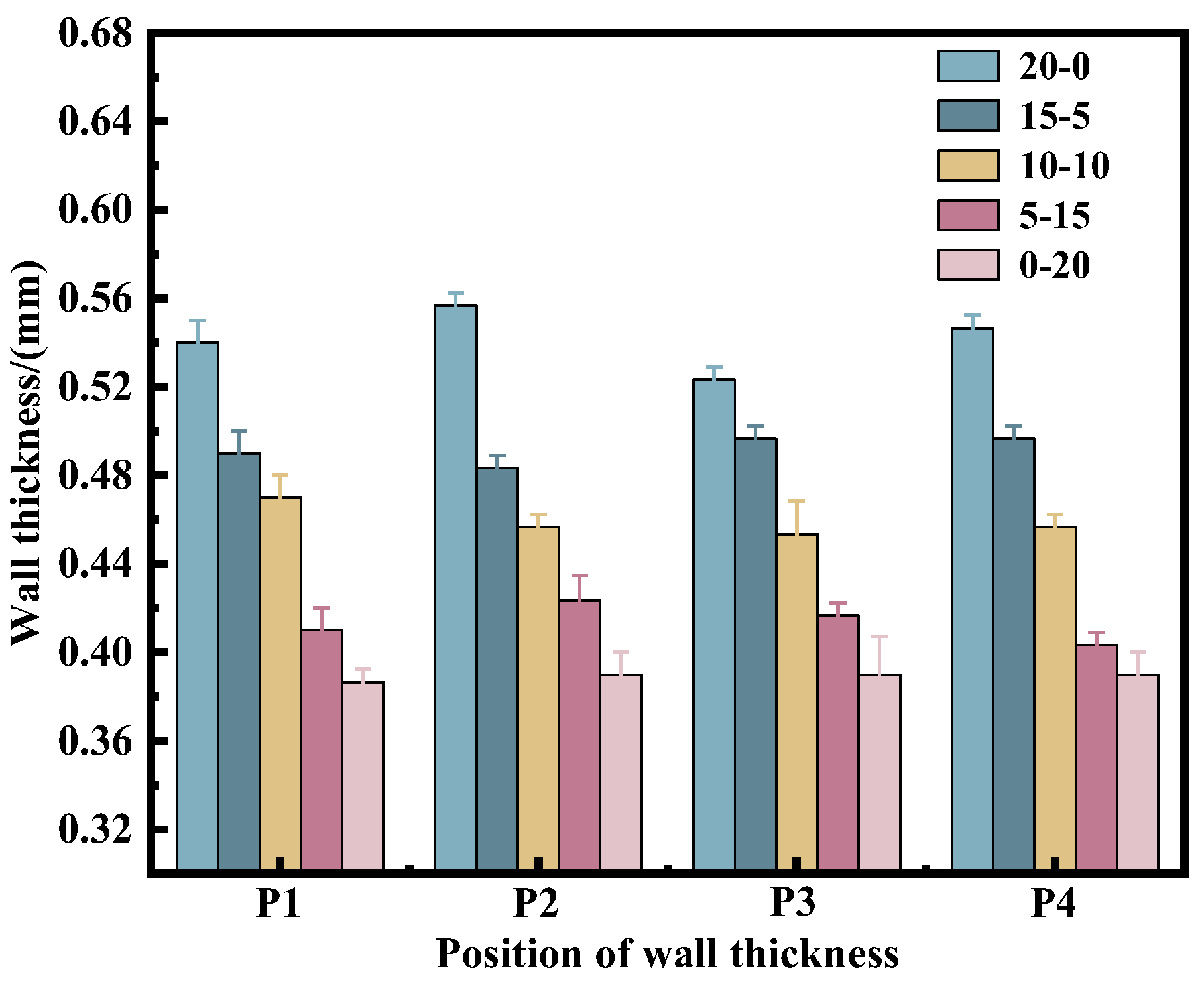
A multi-point measurement method is used to measure the medical microtubule wall thickness. The medical microtubule wall thickness distribution under different channel parameters is shown in Figure 9. The medical microtubule wall thickness of traditional extrusion is significantly greater than that of gas-assisted extrusion. This is because during the process of medical microtubule gas-assisted extrusion, gas has a certain drag effect on the melt, and the melt velocity is increased, resulting in the melt becoming thinner. Under the conditions of 15–5, medical microtubules have a relatively uniform wall thickness, and the wall thickness is close to the design value. As the gas-assisted length increases, the phenomenon of melt thinning becomes more apparent. The distribution and variation of the microtubule wall thickness are consistent with the numerical simulation results, which verifies the correctness of the numerical simulation.
5. Conclusions
- (1)
- This paper studies the influence of mold flow channel parameters on medical microtubule gas-assisted extrusion formation by numerical simulation and experimental analysis. According to the gas-assisted extrusion mechanism of medical microtubules, the physical and mathematical model of the gas-assisted extrusion process of medical microtubules with different parameters was established. Then, the boundary conditions are optimized, and a numerical solution is presented through Polyflow finite element software. Further, the gas-melt interaction and stress distribution are analyzed, and the medical microtube extrusion forming quality and variation law are obtained. Finally, the gas-assisted extrusion experiment is conducted. The simulation and experimental results show that under the 15–5 condition, the quality of medical microtubes is better than other parameters. The shrinkage rates of the inner radius, outer radius, and wall thickness are 2.3%, 4.5%, and 2.2%, respectively, and the average wall thickness is 0.49 mm.
- (2)
- Through numerical simulation and experimental analysis, we obtained the suitable mold flow channel parameters to prepare medical microtubes. However, the medical microtubule gas-assisted extrusion process is complex, and we did not consider the combined effects of other factors. Therefore, our further work will focus on the coupling effects of multiple parameters on medical gas-assisted microtube extrusion.
Author Contributions
X.Z.: Conceptualization, software, writing—original draft preparation, formal analysis, writing—review and editing. X.H.: supervision, project administration, funding acquisition. B.L.: methodology, resources, data curation. S.J.: writing—review and editing. S.R.: formal analysis, investigation. All authors have read and agreed to the published version of the manuscript.
Funding
This work was supported by the National Natural Science Foundation of China [grant numbers: 51863014, 51403615].
Data Availability Statement
Data available on request from the authors.
Conflicts of Interest
The authors declare that they have no known competing financial interest or personal relationship that could have appeared to influence the work reported in this paper.
References
- Yijun, L.; Lin, P.; Min, N. Preparation of High Performance Polyethylene Microtubes via Rotation Extrusion Processing. Polym. Bull. 2019, 1, 31–38. [Google Scholar]
- Lu, G.; Kalyon, D.M.; Yilgör, I.; Yilgör, E. Rheology and extrusion of medical-grade thermoplastic polyurethane. Polym. Eng. Sci. 2003, 43, 1863–1877. [Google Scholar] [CrossRef]
- Ding, W.; Zhao, Z.; Jiang, L.; Jian, X.; Song, Y.; Wang, J. Preparation and evaluation of a UV-curing hydrophilic semi-IPN coating for medical guidewires. J. Coat. Technol. Res. 2021, 18, 1027–1035. [Google Scholar] [CrossRef]
- Pimentel, E.; Costa, P.; Tubio, C.; Vilaça, J.; Costa, C.; Lanceros-Méndez, S.; Miranda, D. Printable piezoresistive polymer composites for self-sensing medical catheter device applications. Compos. Sci. Technol. 2023, 239, 110071. [Google Scholar] [CrossRef]
- Zheng, J.L.; Ge, D.W.; Chen, Y.W.; Wu, H.W. Variation of Tube Diameter and Wall Thickness in Medical Micro-diameter Tube Extrusion. Plastics 2012, 41, 24–27. [Google Scholar] [CrossRef]
- Ren, Z.; Huang, X.; Xiong, Z. Experimental and numerical studies for the gas-assisted extrusion forming of polypropylene micro-tube. Int. J. Mater. Form. 2019, 13, 235–256. [Google Scholar] [CrossRef]
- Liu, T.-K.; Huang, X.-Y.; Ren, Z.; Luo, C.; Tan, J.-M. Analysis of Superimposed Influence of Double Layer Gas Flow on Gas-Assisted Extrusion of Plastic Micro-Tube. Int. Polym. Process. 2020, 35, 158–168. [Google Scholar] [CrossRef]
- Deng, X.; Bin, X.; Zhong, R. Progress on Polymer Gas-Assisted Extrusion Molding. Polym. Mater. Sci. Eng. 2022, 38, 151–158. [Google Scholar] [CrossRef]
- Xiao, X.H. Analysis and Experimental Study of Polymer Micro Tubing Extrusion Flow. Ph.D. Thesis, Central South University, Changsha, China, 2013. [Google Scholar]
- Huang, C.Y.; Liu, H.S.; Huang, X.Y.; Wan, Q.F.; Ren, Z. Numerical Simulation of Gas-assisted Extrusion Process of Microtube. China Plast. Ind. 2015, 43, 44–48. [Google Scholar] [CrossRef]
- Jin, G. Experimental Investigation of Extrusion Process of Double-lumen Micro Tube. JMechE 2012, 48, 19–27. [Google Scholar] [CrossRef]
- Tian, H.; Zhao, D.; Wang, M.; Jin, G.; Jin, Y. Study on extrudate swell of polypropylene in double-lumen micro profile extrusion. J. Mater. Process. Technol. 2015, 225, 357–368. [Google Scholar] [CrossRef]
- Jin, G.-B.; Wang, M.-J.; Zhao, D.-Y.; Tian, H.-Q.; Jin, Y.-F. Design and experiments of extrusion die for polypropylene five-lumen micro tube. J. Mater. Process. Technol. 2014, 214, 50–59. [Google Scholar] [CrossRef]
- Xiao, J.; Liu, H.; Huang, X. Influence of Slip Length of Gas-Assisted Extrusion Die on Pressure Drop and First Normal Stress. Polym. Mater. Sci. Eng. 2009, 25, 167–170. [Google Scholar] [CrossRef]
- Ren, Z.; Huang, X. Effect of gas flow rate on the double gas-assisted extrusion forming of plastic pipes. IOP Conf. Series Earth Environ. Sci. 2019, 267, 042059. [Google Scholar] [CrossRef] [Green Version]
- Liu, T.; Huang, X.; Luo, C.; Wang, D. The Formation Mechanism of the Double Gas Layer in Gas-Assisted Extrusion and Its Influence on Plastic Micro-Tube Formation. Polymers 2020, 12, 355. [Google Scholar] [CrossRef] [PubMed] [Green Version]
- Luo, C.; Huang, X.; Liu, T.; Liu, H. Research on Inner Gas Inflation Improvements in Double-layer Gas-assisted Extrusion of Micro-tubes. Polymers 2020, 12, 899. [Google Scholar] [CrossRef] [PubMed] [Green Version]
- Liu, B.; Huang, X.; Ren, S.; Luo, C. Effect of Pressure Difference between Inner and Outer Gas Layer on Micro-Tube Deformation during Gas-Assisted Extrusion. Polymers 2022, 14, 3559. [Google Scholar] [CrossRef] [PubMed]
- Ren, Z.; Huang, X.; Liu, H.; Deng, X.; He, J. Numerical and experimental studies for gas assisted extrusion forming of molten polypropylene. J. Appl. Polym. Sci. 2015, 132, 42682. [Google Scholar] [CrossRef]
- Thien, N.P.; Tanner, R.I. A new constitutive equation derived from network theory. J. Non-Newton. Fluid Mech. 1977, 2, 353–365. [Google Scholar] [CrossRef]
- Deng, X.Z. Experimental and Theoretical Study on Gas-Assisted Co-Extrusion of Plastic Profile with an Irregular Cross-Section. Ph.D. Thesis, Nanchang University, Nanchang, China, 2014. [Google Scholar]
Figure 1.
Geometric model and finite element model of medical microtubule gas-assisted extrusion. (a) Schematic diagram of double gas-assisted extrusion section; (b) 3D diagram of double gas-assisted extrusion; (c) Schematic diagram of a 2D simplified model of double gas-assisted extrusion; (d) Finite element mesh model; (Ⅰ) non-gas-assisted shaping section; (Ⅱ) gas-assisted shaping section; (Ⅲ) The melt outside the mold.
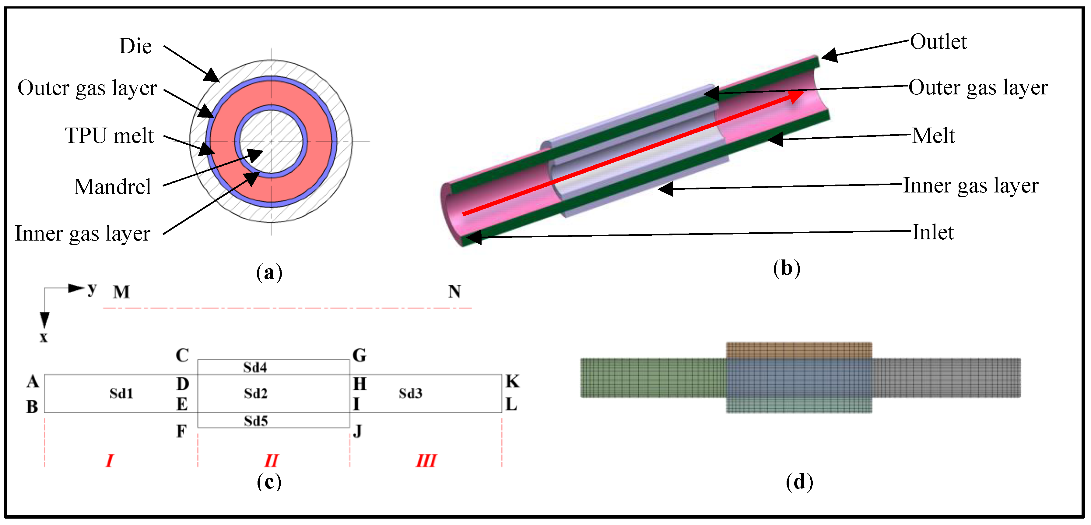
Figure 2.
Variation of medical microtubule size parameters. (a) Inter radius distribution curve; (b) Outer radius distribution curve; (c) Wall thickness distribution curve; (d) Shrinkage rate.
Figure 2.
Variation of medical microtubule size parameters. (a) Inter radius distribution curve; (b) Outer radius distribution curve; (c) Wall thickness distribution curve; (d) Shrinkage rate.
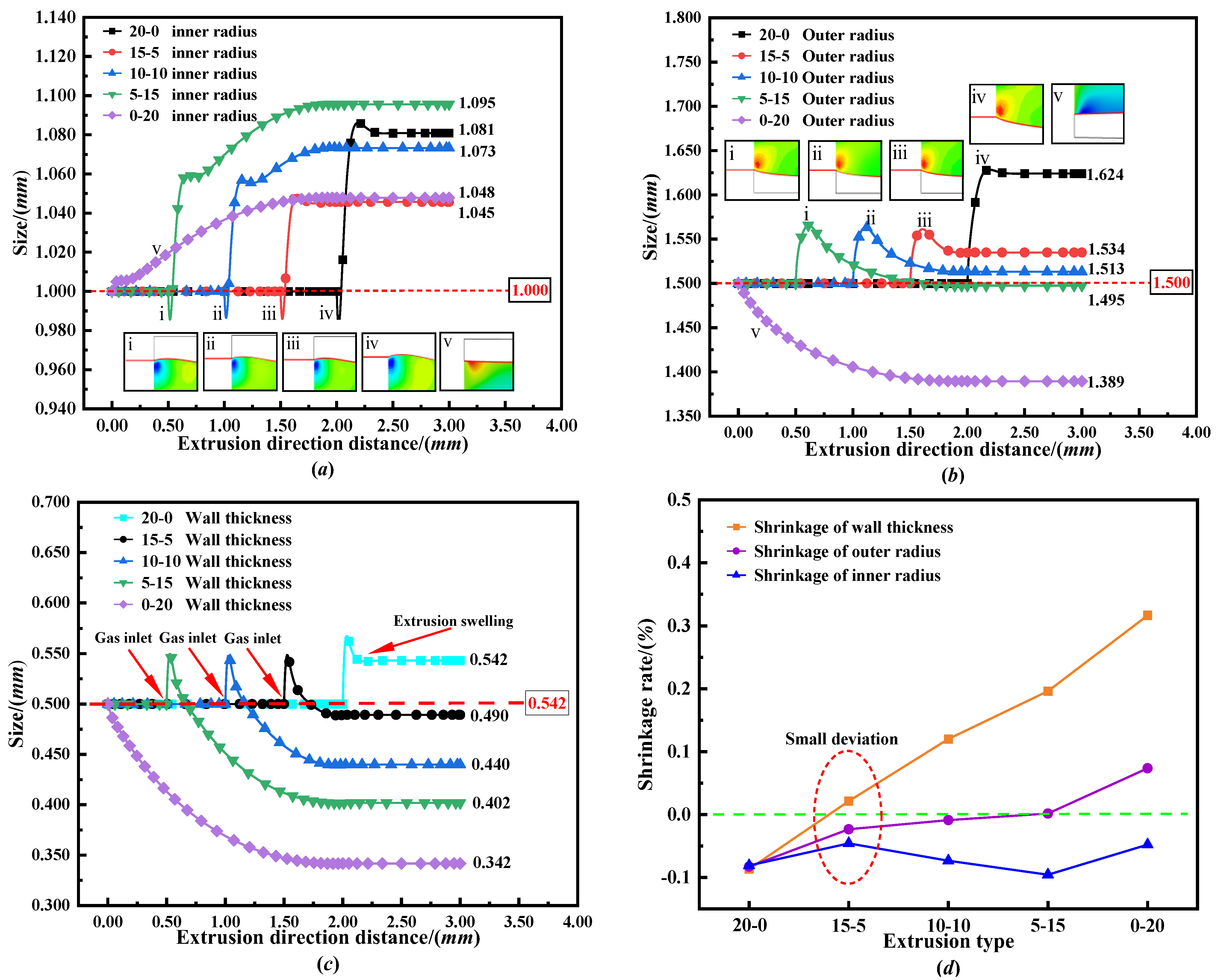
Figure 3.
Cloud diagram of melt radial velocity distribution under different flow path parameters.
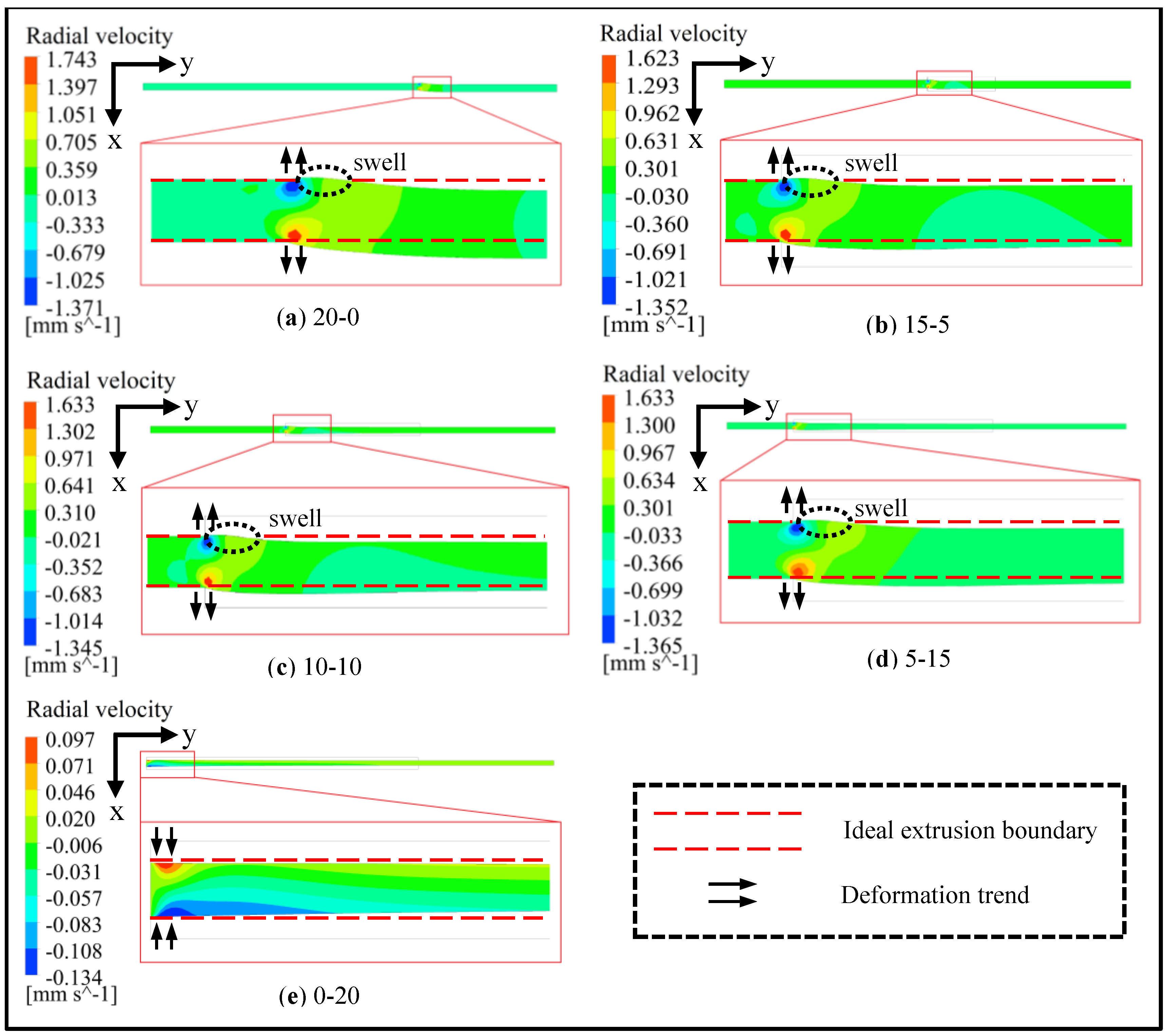
Figure 4.
Cloud diagram of melt axial velocity distribution under different flow path parameters.
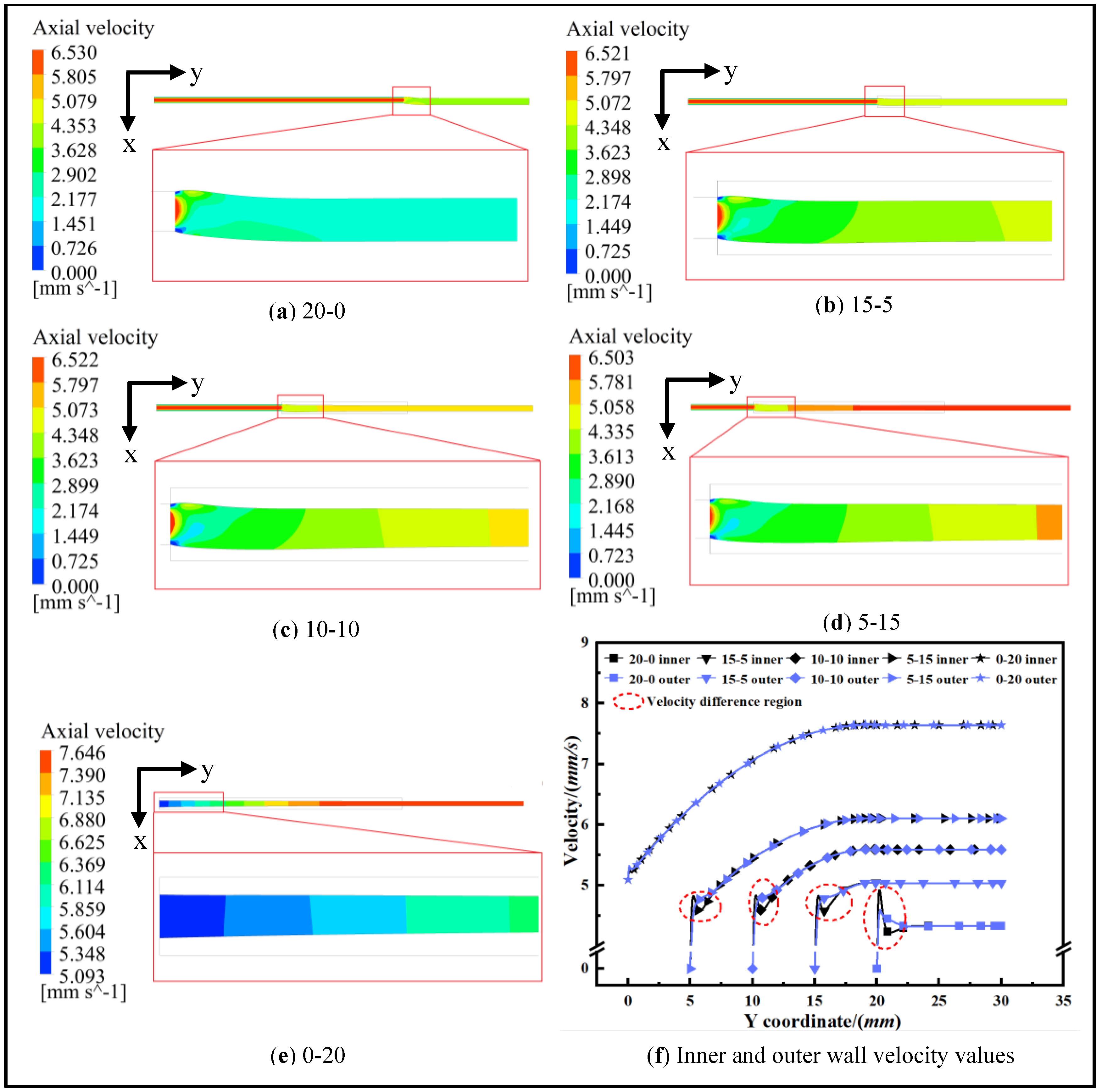
Figure 5.
Pressure distribution of melt inside and outside surface under different flow path parameters. (a) Inner surface pressure distribution of gas-assisted shaping section; (b) Outer surface pressure distribution of gas-assisted shaping section.
Figure 5.
Pressure distribution of melt inside and outside surface under different flow path parameters. (a) Inner surface pressure distribution of gas-assisted shaping section; (b) Outer surface pressure distribution of gas-assisted shaping section.

Figure 6.
First normal stress difference distribution of melt under different flow channel parameters.
Figure 6.
First normal stress difference distribution of melt under different flow channel parameters.
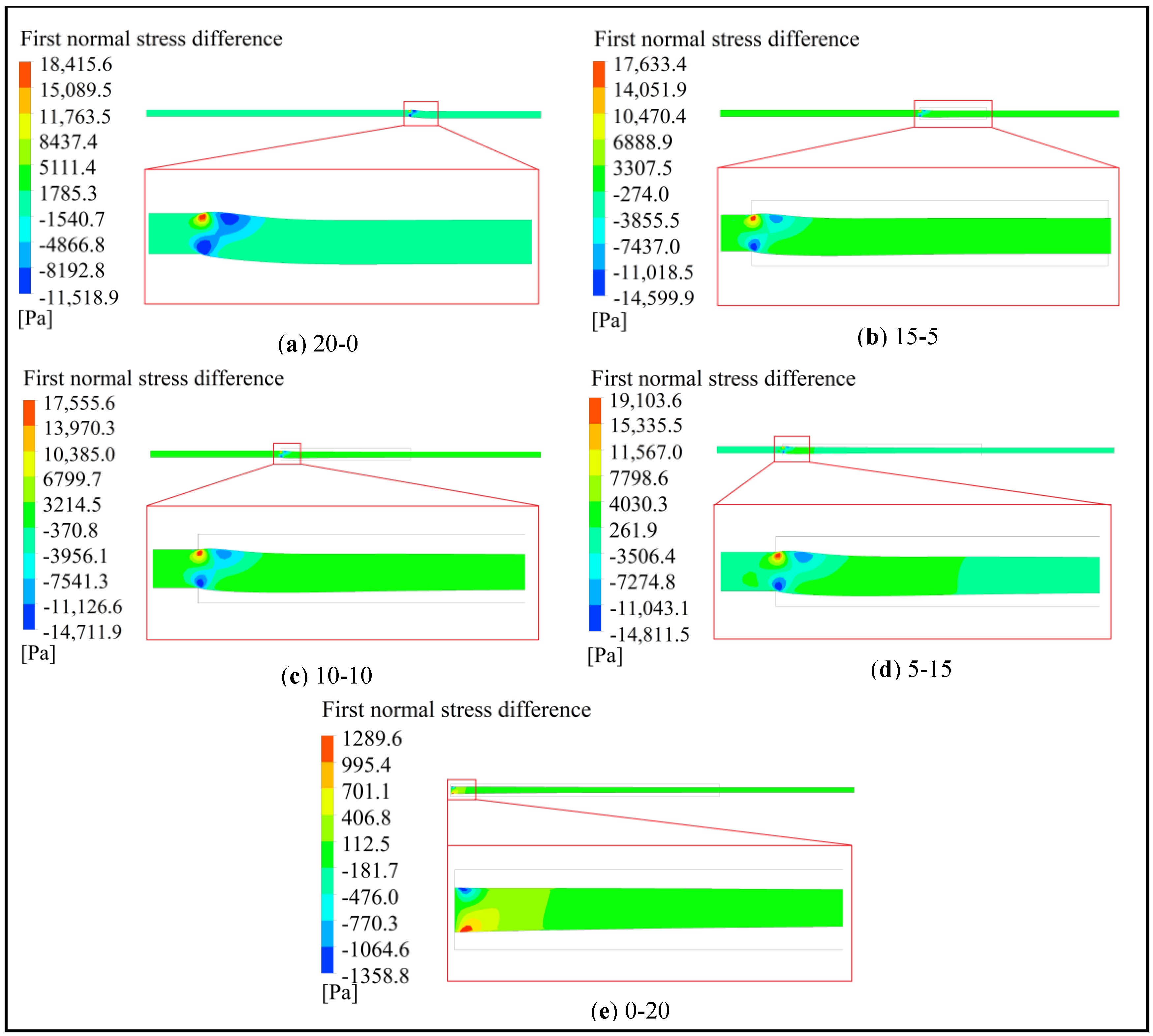
Figure 7.
The double-layer gas-assisted extrusion experimental platform: 1-Air compressor; 2-High-pressure gas cylinder; 3-Pressure gage; 4-Flowmeter; 5,6,7-Air valve; 8,9-Gas heater; 10,11-Pressure gage; 12-Extruder; 13-Extrusion mold; 14-Cooling device; 15-Coupling device; 16-Collecting device; ①-Inlet of melt; ②-Head section; ③-Inner gas inlet; ④-Sprue spreader; ⑤-Clamping ring; ⑥-Link module; ⑦-Outer die; ⑧-Mandril; ⑨-Outer gas inlet; ⑩-Gas-assisted shaping section; ⑪-Non-gas-assisted shaping section.
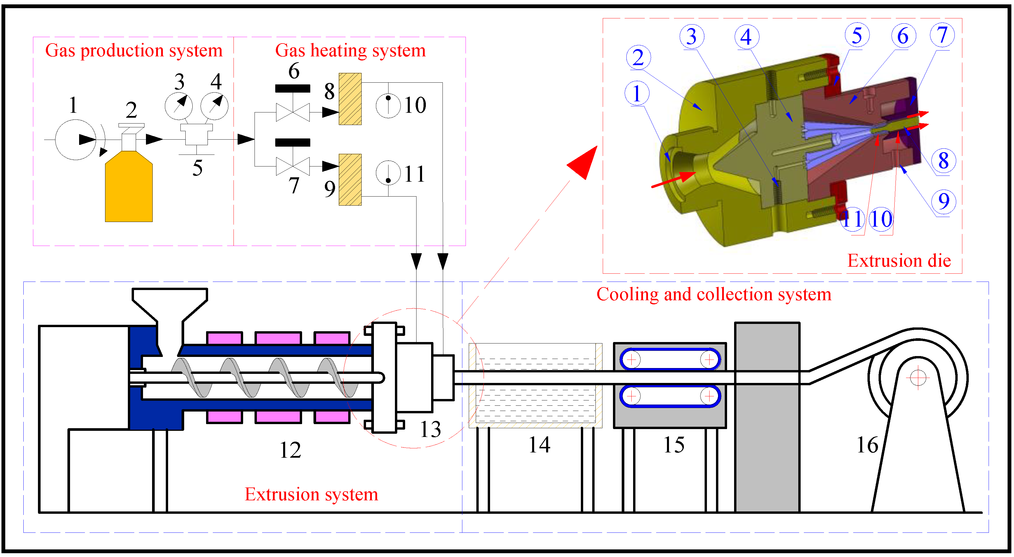
Figure 8.
Results of extrusion experiment: (a) Extrusion result of 20–0; (b) Extrusion result of 15–5; (c) Extrusion result of 10–10; (d) Extrusion result of 5–15; (e) Extrusion result of 0–20.
Figure 8.
Results of extrusion experiment: (a) Extrusion result of 20–0; (b) Extrusion result of 15–5; (c) Extrusion result of 10–10; (d) Extrusion result of 5–15; (e) Extrusion result of 0–20.
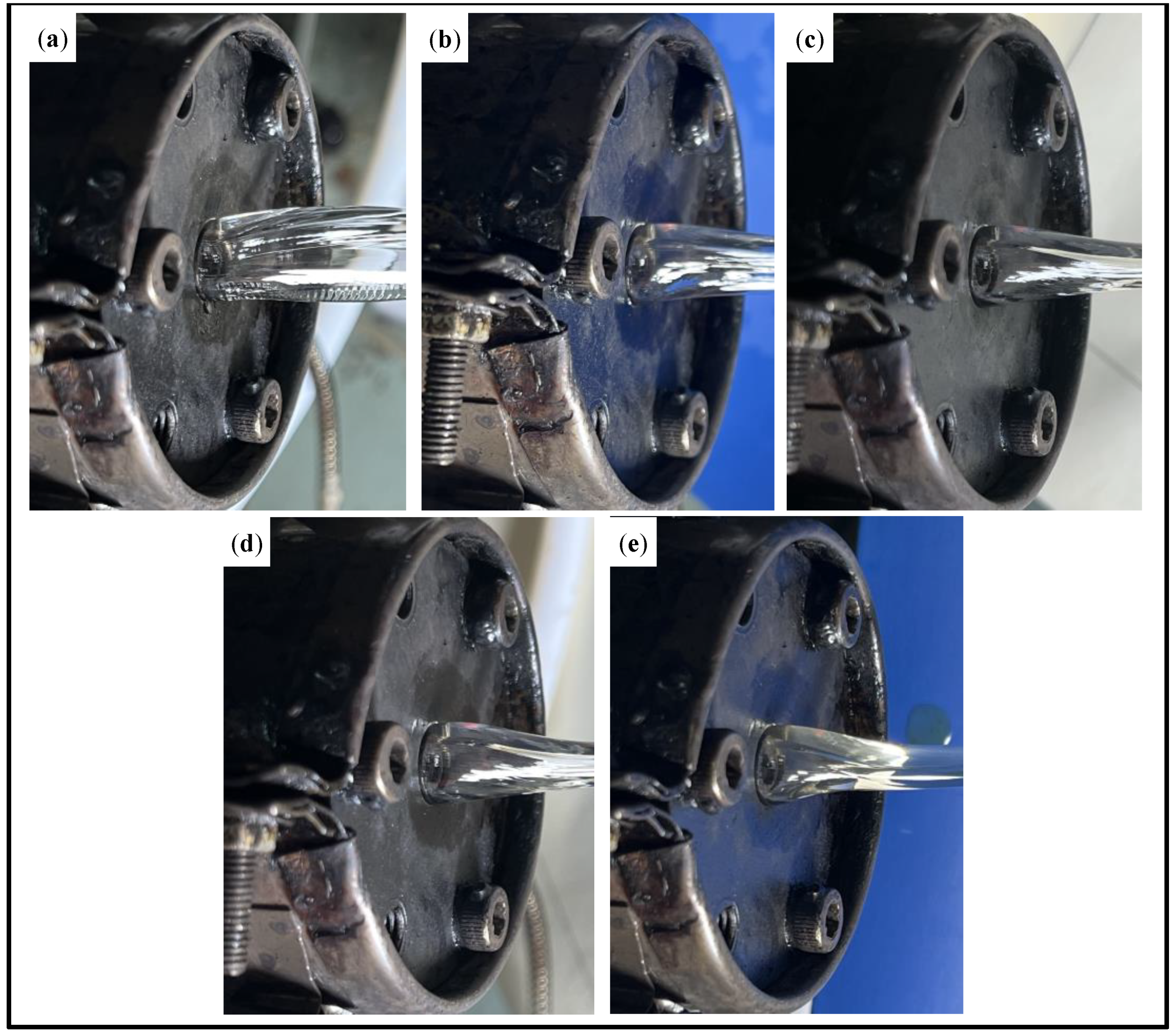
Figure 9.
Wall thickness distribution of medical microtubes under different parameters.

Table 1.
Boundary conditions.
| Type of Boundary Conditions | Boundaries | Boundary Conditions |
|---|---|---|
| Inlet boundary | AB | melt inlet boundary: flow inlet boundary |
| CD, EF | gas inlet boundary: pressure inlet boundary | |
| Wall boundary | AD, BE | melt–mold wall boundary: non-slip boundary conditions |
| CG | gas–mold wall boundary: complete slip boundary conditions | |
| Gas–liquid interface boundary | DH, EI | interface boundary |
| Free surface boundary | HK, IL | free surface boundary |
| Outlet boundary | KL, GH, IJ | outlet boundary |
Table 2.
Physical parameters of PP melt and gas.
| Parameters | PP Melt | Gas |
|---|---|---|
| η1/(Pa·s) | 8823 | 2.6 × 10⁻⁵ |
| λ/(s) | 0.1 | 0 |
| ε | 0.15 | 0 |
| ξ | 0.44 | 0 |
| η1r | 0.12 | 0 |
| qk/(W/(m·K)) | 0.22 | 0.037 |
| Cv/(J/(Kg·K)) | 1883 | 1026 |
Table 3.
Experimental parameters.
| Experimental Conditions | 5–15/10–10/15–5/0–20 | 20–0 |
|---|---|---|
| Inner gas pressure/(Pa) | 7500 | / |
| Outer gas pressure/(Pa) | 6500 | / |
| Die temperature/(°C) | 190 | 190 |
| Gas temperature/(°C) | 190 | 190 |
| Motor frequency/(Hz) | 4 | 4 |
| Pulling speed(r/min) | 4 | 4 |
Disclaimer/Publisher’s Note: The statements, opinions and data contained in all publications are solely those of the individual author(s) and contributor(s) and not of MDPI and/or the editor(s). MDPI and/or the editor(s) disclaim responsibility for any injury to people or property resulting from any ideas, methods, instructions or products referred to in the content. |
© 2023 by the authors. Licensee MDPI, Basel, Switzerland. This article is an open access article distributed under the terms and conditions of the Creative Commons Attribution (CC BY) license (https://creativecommons.org/licenses/by/4.0/).
Share and Cite
MDPI and ACS Style
Zhang, X.; Huang, X.; Liu, B.; Jiang, S.; Ren, S. Effect of Mold Flow Channel Parameters on Gas-Assisted Extrusion of Medical Microtubules. Processes 2023, 11, 1973. https://doi.org/10.3390/pr11071973
AMA Style
Zhang X, Huang X, Liu B, Jiang S, Ren S. Effect of Mold Flow Channel Parameters on Gas-Assisted Extrusion of Medical Microtubules. Processes. 2023; 11(7):1973. https://doi.org/10.3390/pr11071973
Chicago/Turabian StyleZhang, Xiaohui, Xingyuan Huang, Bin Liu, Shiyu Jiang, and Shaoyi Ren. 2023. "Effect of Mold Flow Channel Parameters on Gas-Assisted Extrusion of Medical Microtubules" Processes 11, no. 7: 1973. https://doi.org/10.3390/pr11071973
Note that from the first issue of 2016, this journal uses article numbers instead of page numbers. See further details here.