
Comprehensive Design and Propagation Study of a Compact Dual Band Antenna for Healthcare Applications


Abstract
:1. Introduction
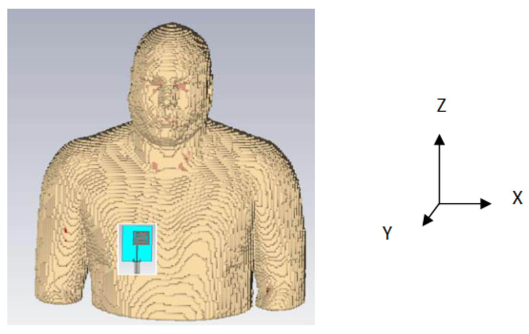
2. On-Body Performance Parameters of Dual Band PIFA
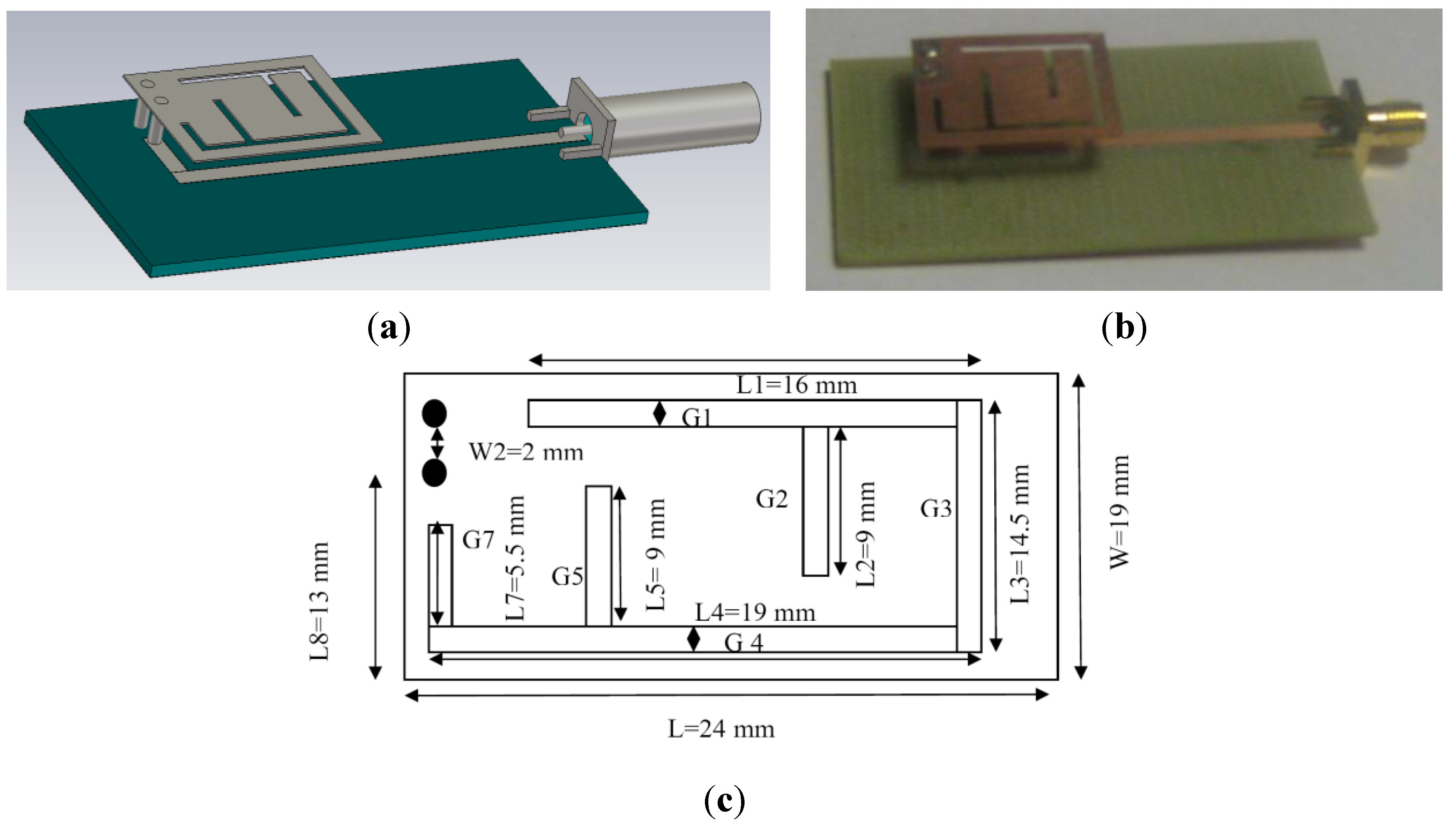
2.1. Antenna Design


| Antenna Elements | Dimension |
|---|---|
| Ground plane | 63 × 34 mm2 |
| Slit width (G) | 1 mm |
| Shoring pin height | 6.92 mm |
| Shoring pin diameter | 1.6 mm |
| Feeding pin height | 5.3 mm |
| Feeding pin diameter | 1.6 mm |
| Width of feed line | 2.4 mm |
| Length of feed line | 51 mm |
| Length of Radiating PIFA (L) | 24 mm |
| Width of Radiating PIFA (W) | 19 mm |
| Thickness of Radiating PIFA | 0.25 mm |
| Total length of the slit (L1~L7) | 72 mm |
| Antenna volume | 63 × 34 × 7 mm3 |
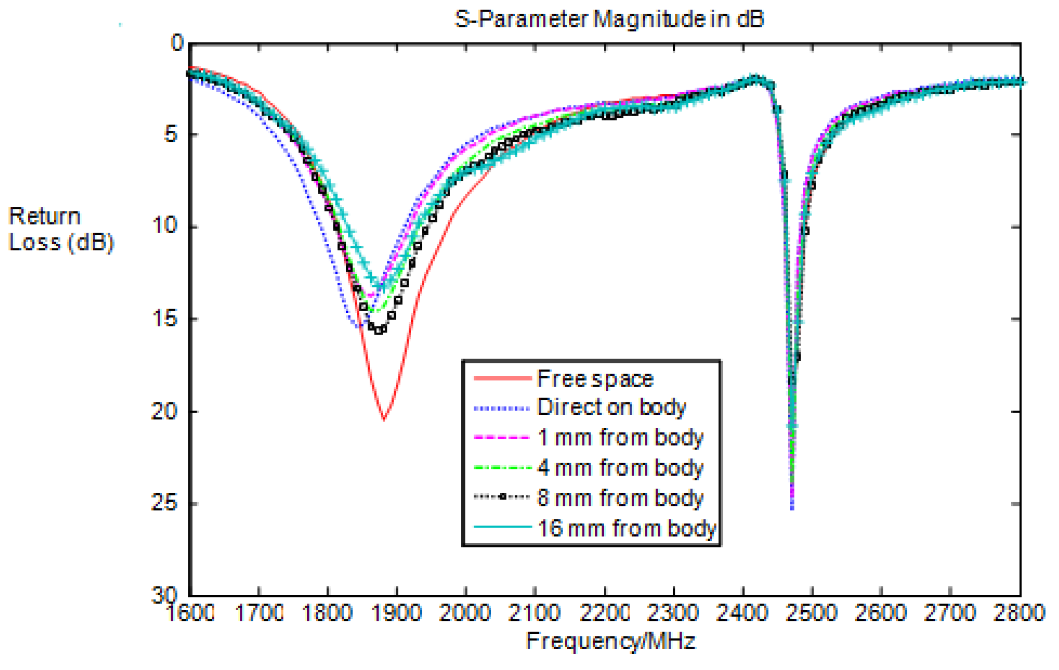
2.2. Return Loss

| Parameter | Low Band | High Band | ||
|---|---|---|---|---|
| Free Space | On-body | Free Space | On-body | |
| Resonance fc (MHz) | 1914 | 1909 | 2462.5 | 2463 |
| Bandwidth (10 dB) | 117.47 | 122.65 | 17 | 12.53 |
| Gain (dBi) | 3.72 | 3.74 | 3.69 | 3.08 |
| Radiation efficiency (%) | 98.98 | 58.03 | 99.30 | 52.0 |
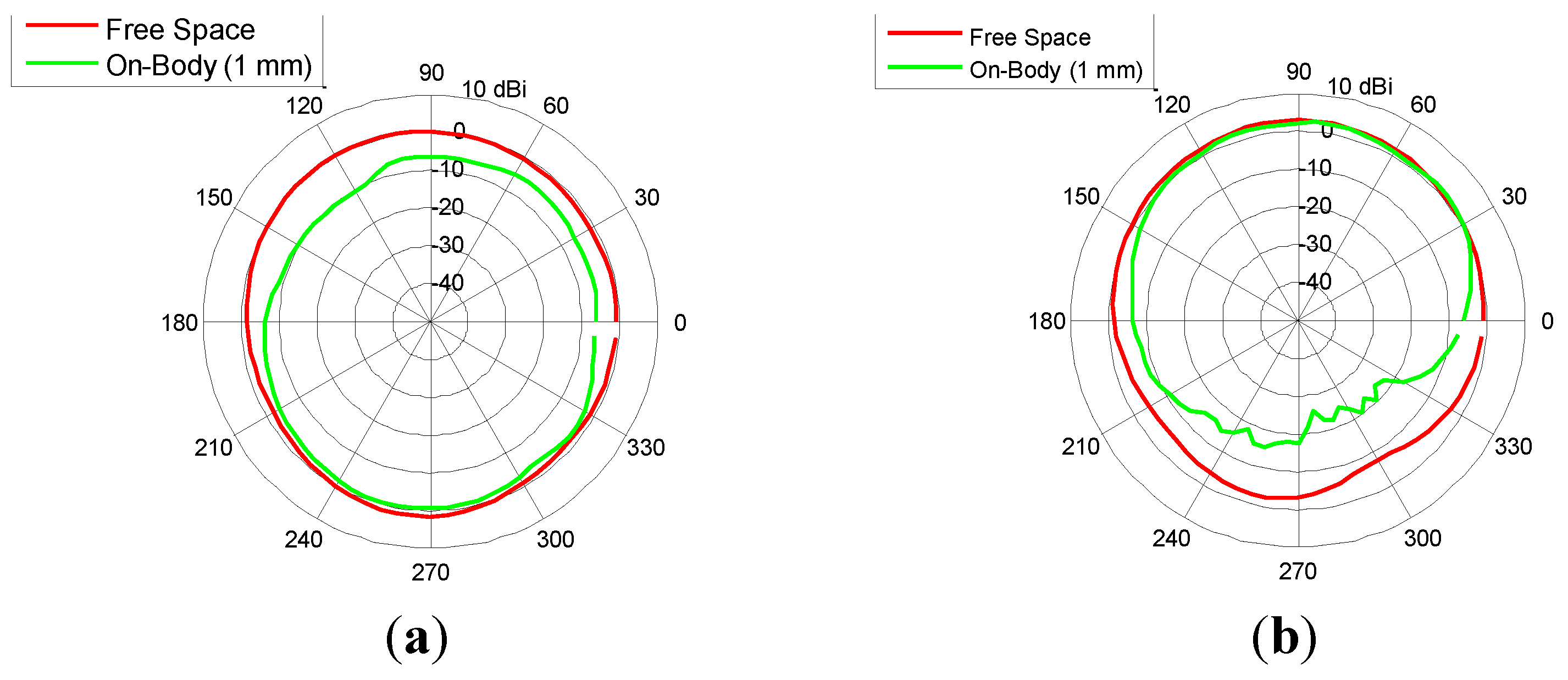
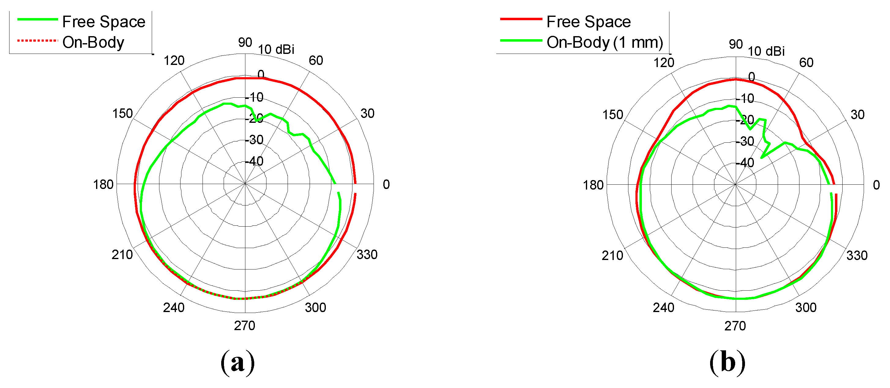
2.3. Radiation Pattern


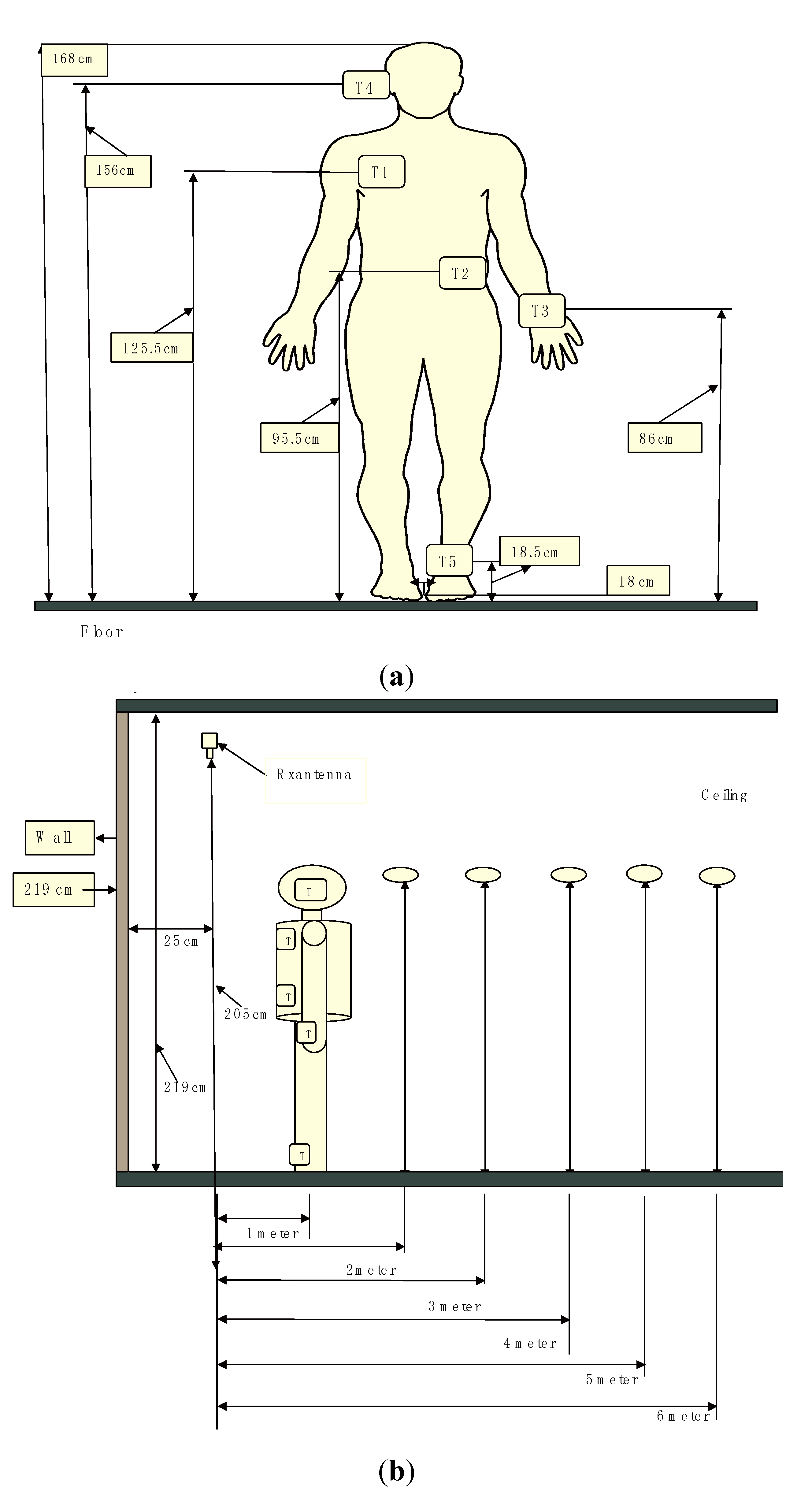
3. Investigation of On-Body Radio Propagation Channels at 2.45 GHz

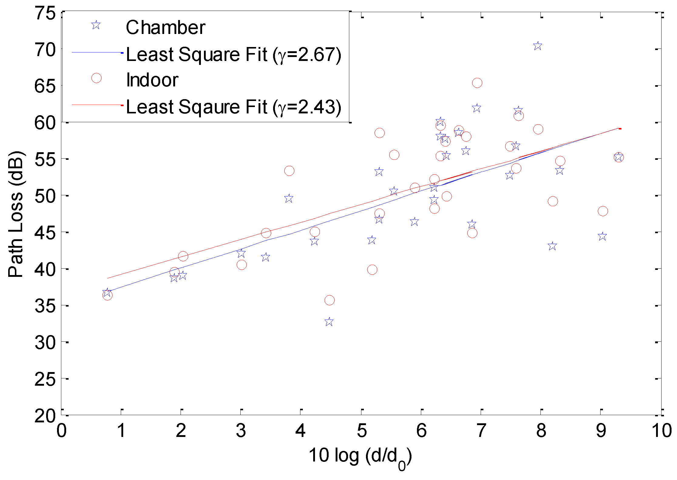
3.1. Path Loss vs. Distance
| Path Loss Parameters | Chamber | Indoor |
|---|---|---|
| γ | 2.67 | 2.43 |
| PLdB(d0) (dB) | 35 | 36.7 |
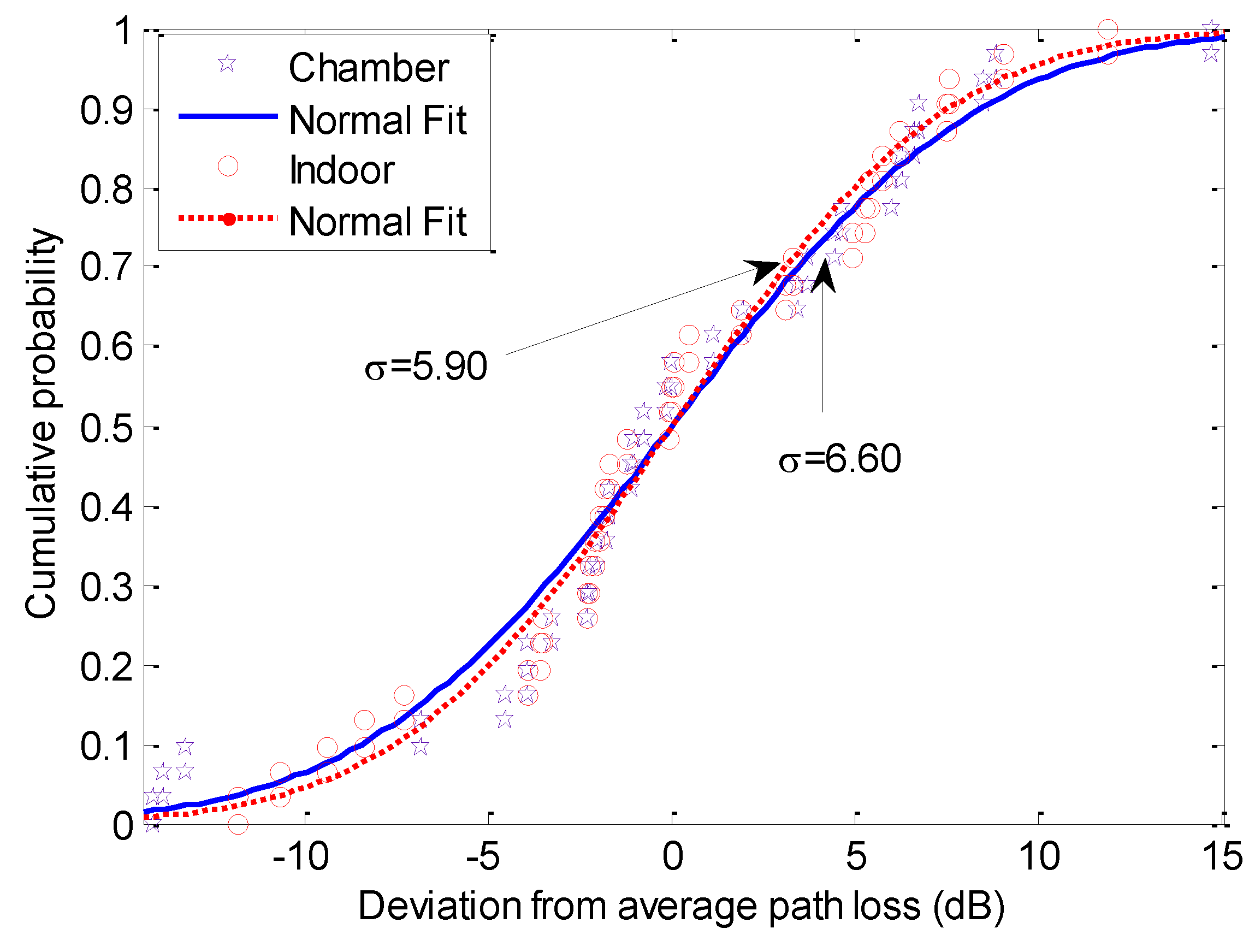
| σ (dB) | 6.60 | 5.90 |


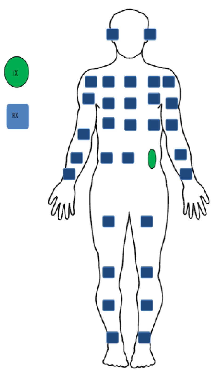
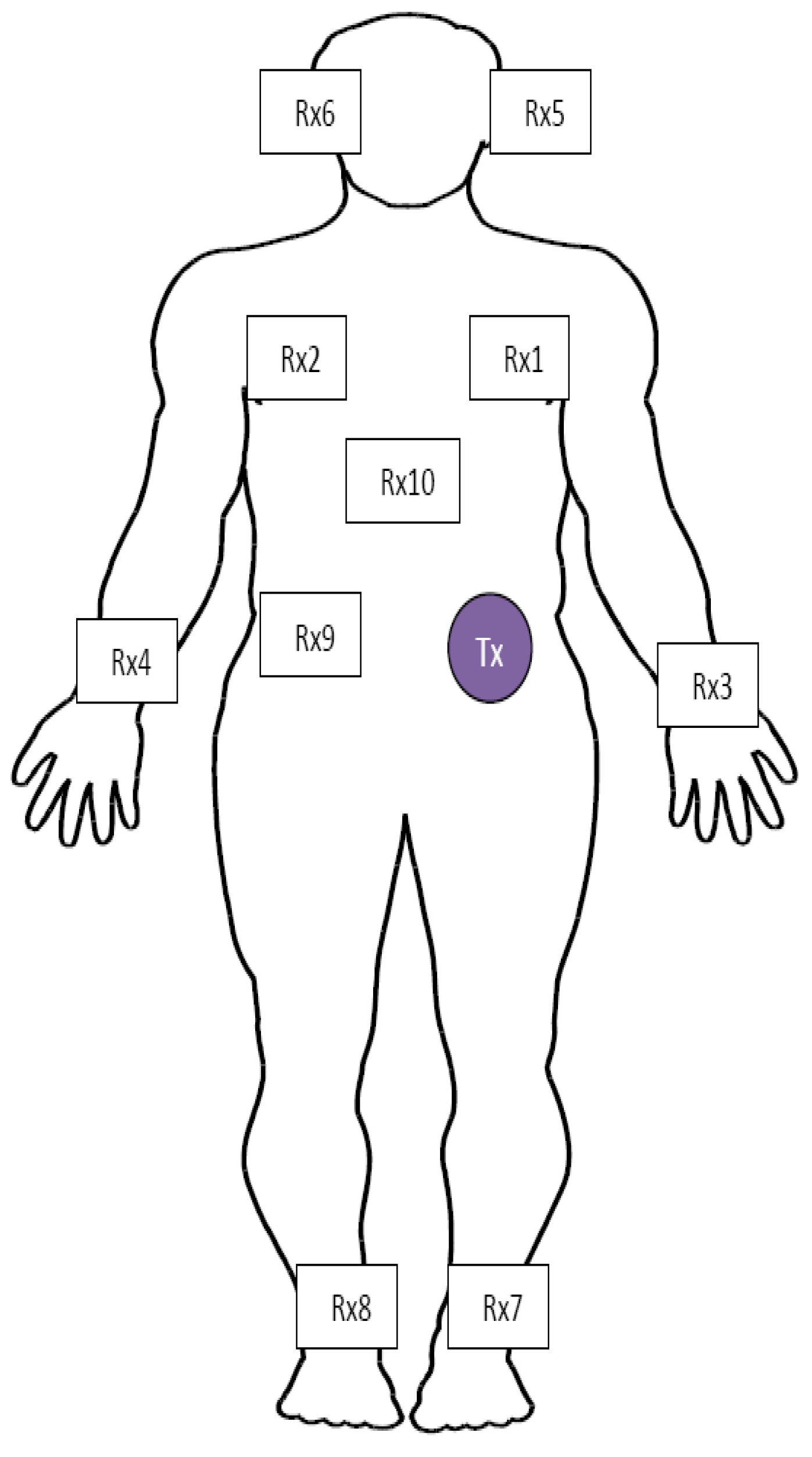
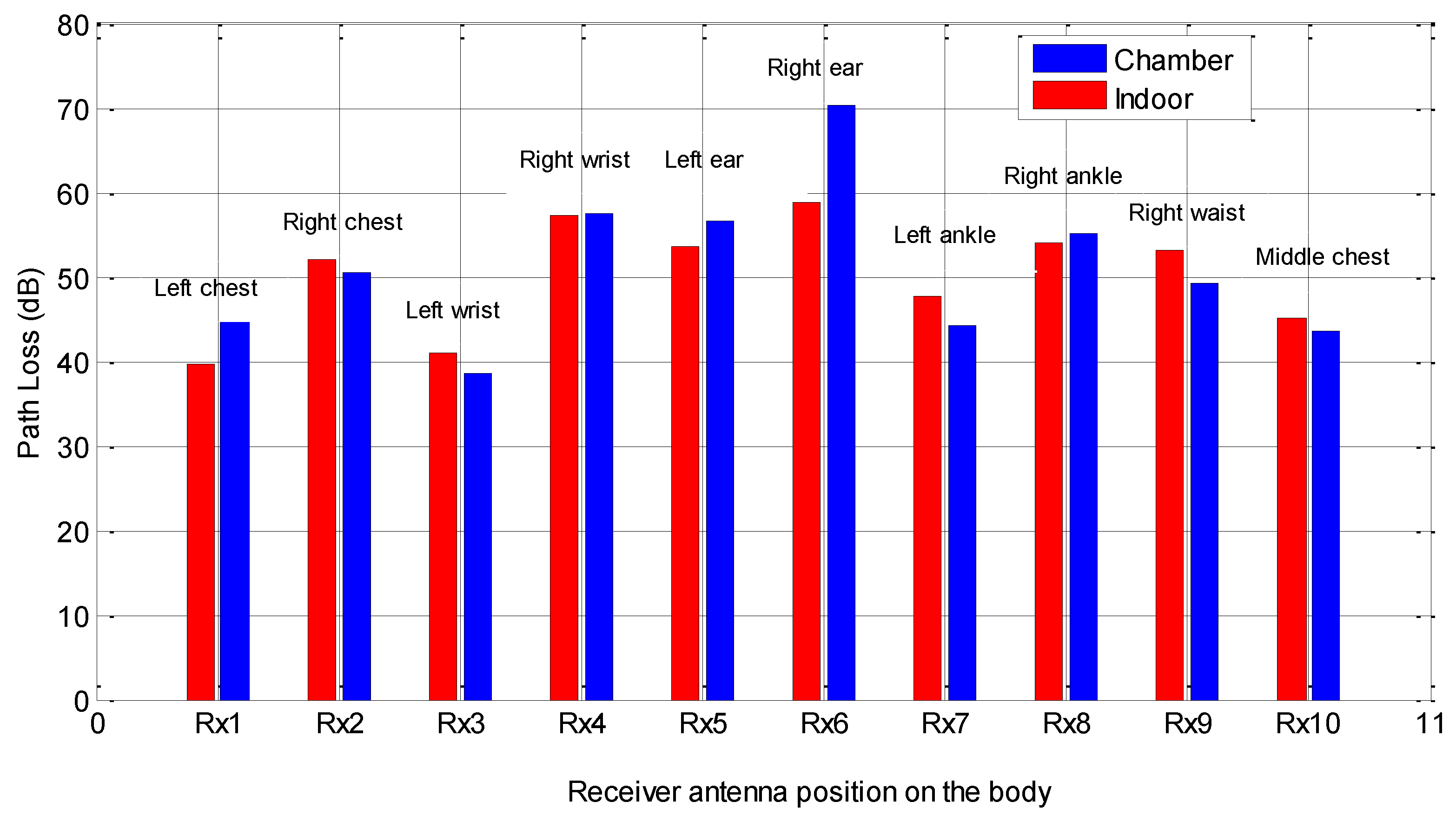
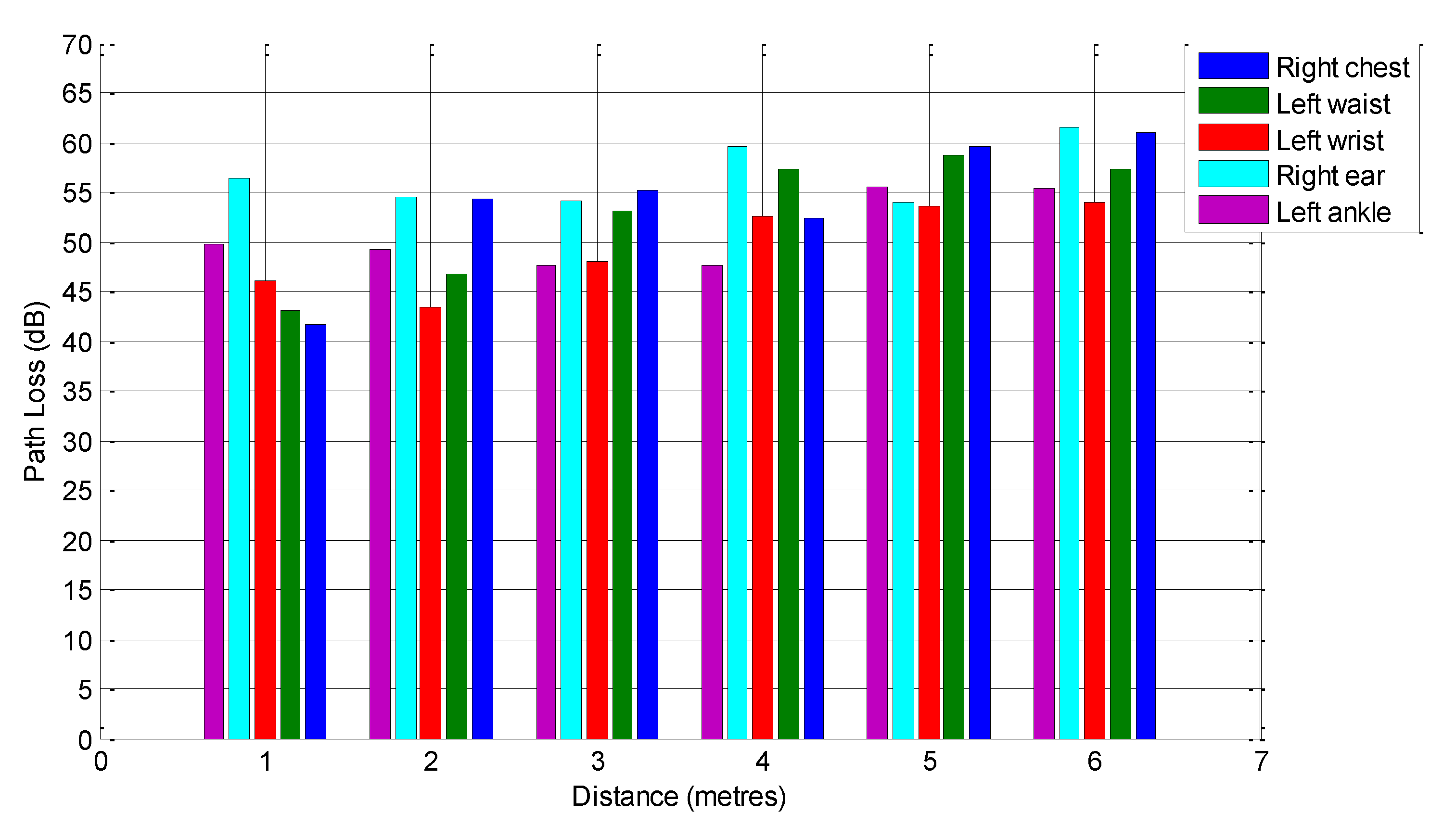
3.2. On-Body Radio Channel Path Loss Characterization at 2.45 GHz


4. Investigation of Off-Body Radio Propagation Channels at 1.9 GHz
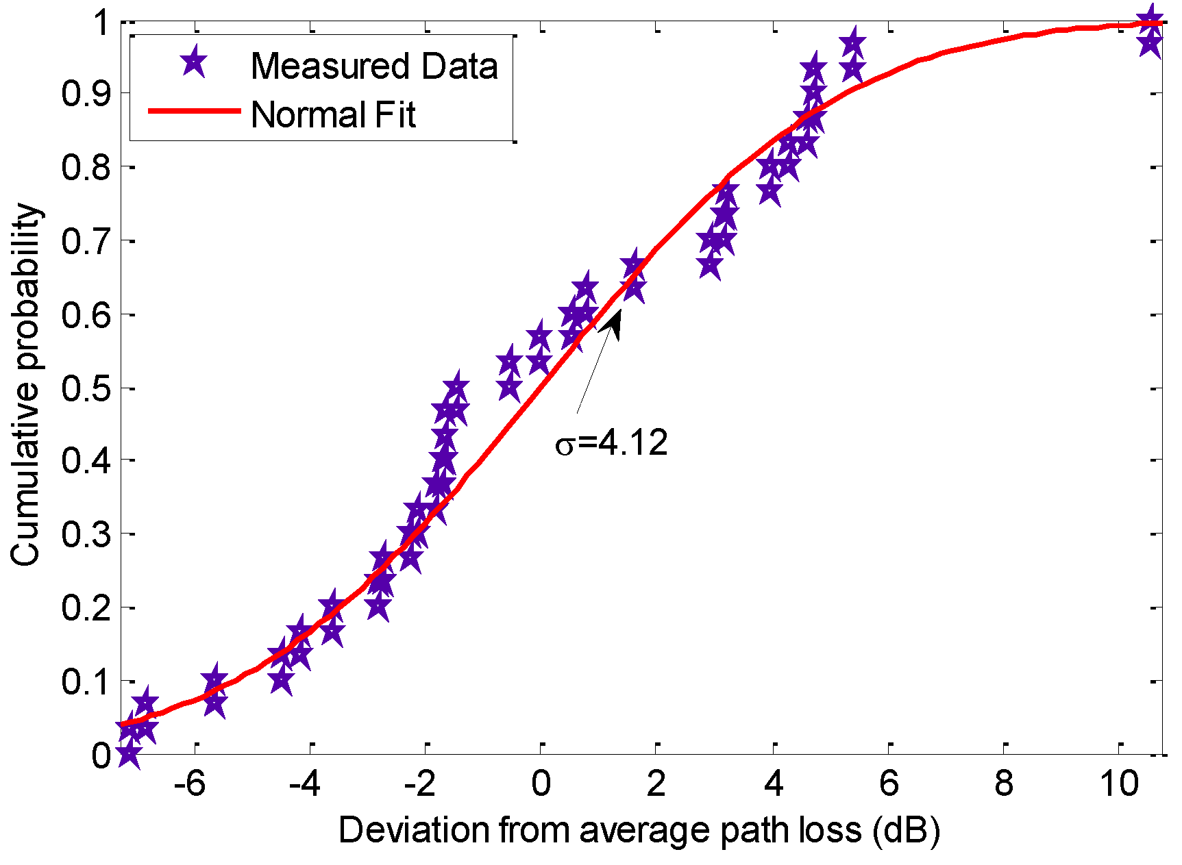
4.1. Path Loss vs. Distance

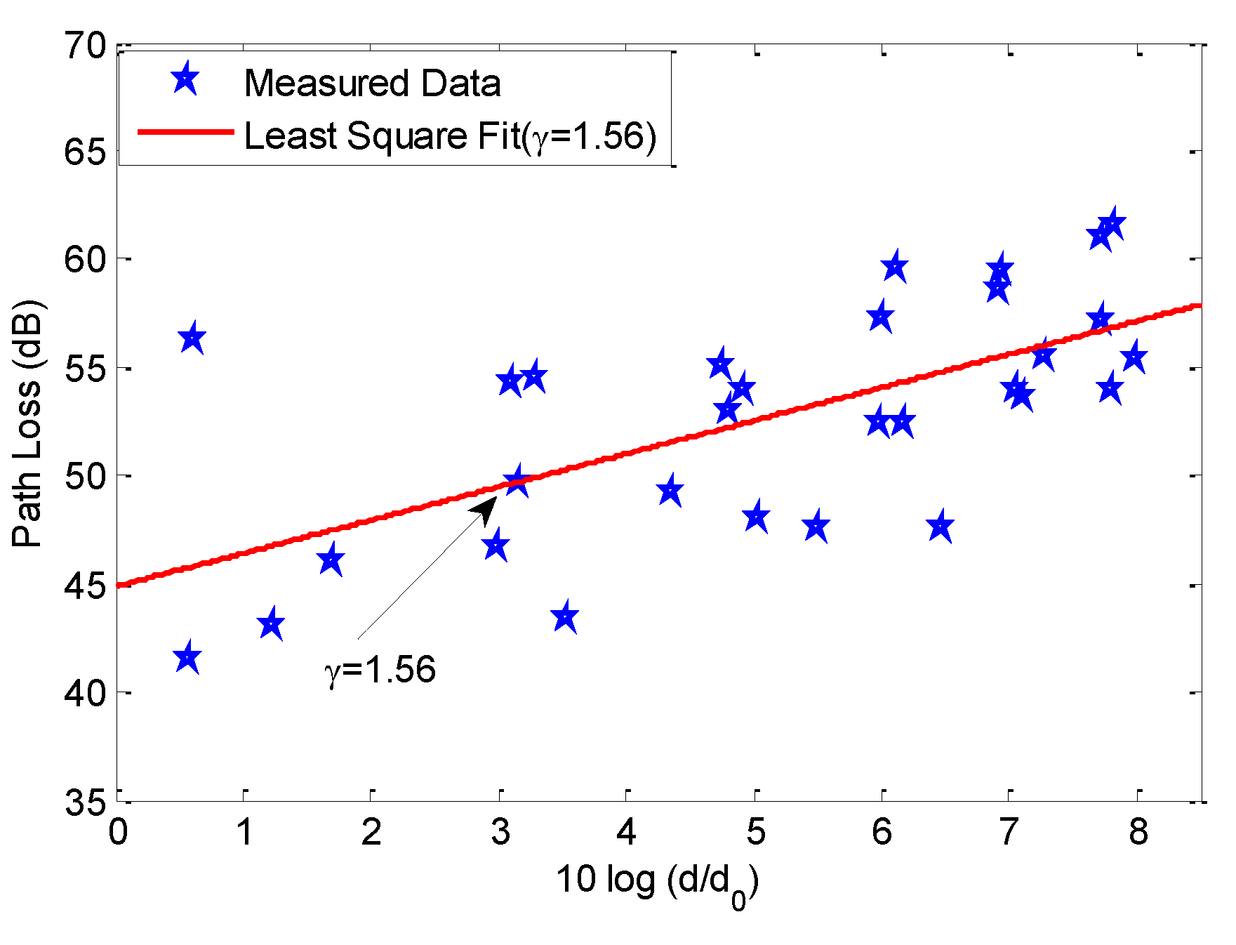
| Path Loss Parameters | Results |
|---|---|
| γ | 1.56 |
| PLdB(d0) (dB) | 44.9 |
| σ (dB) | 4.12 |
4.2. Off-Body Radio Channel Path Loss Characterization at 1.9 GHz

5. Conclusions
Acknowledgments
Author Contributions
Conflicts of Interest
References
- WSN for Healthcare: A Market Dynamics Report. Available online: http://www.onworld.com/healthcare.index.html (accessed on 7 August 2008).
- Hall, P.S.; Hao, Y. Antennas and Propagation for Body-Centric Wireless Communications, 2nd ed.; Artech House: Norwood, MA, USA, 2006. [Google Scholar]
- Alomainy, A.; Hao, Y.; Davenport, D.M. Parametric Study of Wearable Antennas Varying Distances from the Body and Different On-Body Positions. In Proceedings of the IET Seminar on Antennas and Propagation for Body-Centric Wireless Communications, London, UK, 24 April 2007; pp. 84–89.
- Scanlon, W.G.; Evans, N.E. Numerical analysis of body worn UHF antenna systems. Electron. Commun. Eng. J. 2001, 13, 53–64. [Google Scholar] [CrossRef]
- Hall, P.S.; Hao, Y.; Nechayev, Y.I.; Alomainy, A.; Constantinou, C.C.; Parini, C.G.; Kamruddin, M.R.; Salim, T.Z.; Hee, D.T.M.; Dubrovka, R.; et al. Antennas and propagation for on body communication systems. IEEE Antennas Propag. Mag. 2007, 49, 41–58. [Google Scholar] [CrossRef]
- Alomainy, A.; Hao, Y.; Pasveer, F. Numerical and experimental evaluation of a compact sensor antenna for healthcare devices. IEEE Trans. Med. Circuits Syst. 2007. [Google Scholar] [CrossRef]
- Conway, G.A.; Scanlon, W.G. Antennas for over body-surface communication at 2.45 GHz. IEEE Trans. Antennas Propag. 2009, 57, 844–855. [Google Scholar] [CrossRef]
- Scanlon, W.G.; Chandran, A. Stacked-patch antenna with switchable propagation mode for UHF body-centric communications. In Proceedings of the IEEE International Workshop on Antenna Technology (IWAT), Santa Monica, CA, USA, 2–7 March 2009.
- Alomainy, A.; Hao, Y.; Owadally, A.; Parini, C.G.; Hall, P.S.; Constantinou, C.C. Statistical analysis and performance evaluation for on-body radio propagation with microstrip patch antennas. IEEE Trans. Antenna Propag. 2007, 55, 245–248. [Google Scholar] [CrossRef]
- Nechayev, Y.I.; Hall, P.S.; Hu, Z.H. Characterisation of narrowband communication channels on the human body at 2.45 GHz. IET Microw. Antenna Propag. 2010, 4, 722–732. [Google Scholar] [CrossRef]
- Cotton, S.L.; Scanlon, W.G. An experimental investigation into the influence of user state and environment on fading characteristics in wireless body area networks at 2.45 GHz. IEEE Trans. Wirel. Commun. 2009, 8, 6–12. [Google Scholar] [CrossRef]
- Hausman, S.; Januszkiewicz, L. Impact of indoor environment on path loss in body area networks. Sensors 2014, 14, 19551–19560. [Google Scholar]
- Khan, M.M.; Abbasi, Q.H.; Alomainy, A.; Parini, C. Experimental investigation of subject-specific on-body radio propagation channels for body-centric wireless communications. Electronics 2014, 3, 26–42. [Google Scholar] [CrossRef]
- Khan, M.M.; Monsurul Alam, A.K.M.; Kumer, P. Investigation of a compact ultra wideband antenna for wearable applications. Int. J. Commun. Antenna Propag. 2014, 4, 124–129. [Google Scholar]
- Khan, M.M.; Abbasi, Q.H.; Rahman, M.; Ashique, R.H. Experimental Study of On-Body Radio Channel Performance of a Compact Ultra Wideband Antenna. J. Electromagn. Anal. Appl. 2015, 7, 1–9. [Google Scholar]
- Abbasi, Q.H.; Khan, M.M.; Alomainy, A.; Hao, Y. Radio Channel Characterisation and OFDM-Based Ultra Wideband System Modelling for Body-Centric Wireless Networks. In Proceedings of the International Conference on Body Sensor Networks (BSN’11), Dallas, TX, USA, 23–25 May 2011; pp. 89–94.
- Sun, Y.Y.; Cheung, S.W.; Yuk, T.I. Planar monopoles with different radiator shapes for UWB Body-Centric Wireless Communications. J. Eng. 2013. [Google Scholar] [CrossRef]
- Abbasi, Q.H.; Khan, M.M.; Liaqat, S.; Kamran, M.; Alomainy, A.; Hao, Y. Experimental investigation of ultrawide band diversity techniques for on-body radio communications. Prog. Electromagn. Res. C 2013, 34, 165–181. [Google Scholar] [CrossRef]
- Sani, A.; Hao, Y. Modeling of path loss for ultrawide band body centric wireless communications. In Proceedings of the International Conference on Electromagnetics in Advance Applications, Torino, Italy, 14–18 September 2009; pp. 998–1001.
- Alabidi, E.S.; Kamarudin, M.R.; Rahman, T.A.; Khalily, M.; Abdulrahman, A.Y.; Jamlos, M.F.; Jais, M.I. Radiation characteristics improvement of monopole antenna for WBAN applications. Int. J. Multimed. Ubiquitous Eng. 2014, 9, 53–64. [Google Scholar] [CrossRef]
- Sagor, M.H.; Abbasi, Q.H.; Alomainy, A.; Hao, Y. Compact and conformal ultra wideband antenna for wearable applications. In Proceedings of the 5th European Conference on Antenna and Propagation, Rome, Italy, 11–15 April 2011.
- Rahman, A.; Alomainy, A.; Hao, Y. Compact body-worn coplanar waveguide fed antenna for UWB body-centric wireless communications. In Proceedings of the European Conference on Antenna and Propagations (EuCAP), Edinburgh, UK, 11–16 November 2007.
- Klemm, M.; Kovcs, I.Z.; Pedersen, G.F.; Troster, G. Novel small-size directional antenna for UWB WBAN/WPAN applications. IEEE Trans. Antennas Propag. 2005, 53, 3884–3896. [Google Scholar] [CrossRef]
- See, T.S.P.; Zhi-Ning, C. Experimental characterization of UWB antennas for on-body communications. IEEE Trans. Antennas Propag. 2009, 57, 866–874. [Google Scholar] [CrossRef]
- Khan, M.M.; Abbasi, Q.H.; Alomainy, A.; Hao, Y. Performance of ultra wideband wireless tags for on-body radio channel characterisation. Int. J. Antennas Propag. 2012, 2012, 1–10. [Google Scholar] [CrossRef]
- Khan, M.M.; Abbasi, Q.H.; Alomainy, A.; Hao, Y.; Parini, C. Experimental characterisation of ultra-wideband off-body radio channels considering antenna effects. IET Microw. Antennas Propag. 2013, 7, 370–380. [Google Scholar] [CrossRef]
- Khan, M.M.; Abbasi, Q.H.; Alomainy, A.; Hao, Y. Study of Line of Sight (LOS) and Non Line of Sight (NLOS) Ultrawideband Off-Body Radio Propagation for Body-centric Wireless Communications in Indoor. In Proceedings of the 5th European Conference on Antennas and Propagation (EUCAP, 11), Rome, Italy, 11–15 April 2011; pp. 110–114.
- Balanis, C.A. Antenna Theory Analysis and Design, 3rd ed.; John Wiley and Sons, Inc.: Hoboken, NJ, USA, 2005. [Google Scholar]
- Electronic imaging: Board of regents. National Institute of Health National Library of Medicine USA,Bard of regents, Bethesda, MD, Technical Report NH 90–2197, 1990. Available online: http://www.brooks.af.mil/AFRL/HED/hedr (accessed on 20 October 2010).
- Gabriel, C.; Gabriel, S. Compilation of the dielectric properties of body tissues at RF and microwave frequencies, 1999. 1999. Available online: http://www.brooks.af.mil/AFRL/HED/hedr/reports/dielectric/Title/Title.html (accessed on 5 November 2010).
- Calculation of the dielectric properties of body tissues. Institute for Applied Physics, Italian National Research Council. Available online: http://niremf.ifac.cnr.it/tissprop/ (accessed on 5 November 2010).
- Alomainy, A.; Sani, A.; Rahman, A.; Santas, J.G.; Hao, Y. Transient characteristics of wearable antennas and radio propagation channels for ultra-wideband body-centric wireless communications. IEEE Trans. Antennas Propag. 2009, 57, 875–884. [Google Scholar] [CrossRef]
- Gassemzadeh, S.S.; Jana, R.; Rice, C.W.; Turin, W.; Tarohk, V. A statistical path loss model for in- home UWB channels. In Proceedings of the IEEE Conference on Ultrawide Band Systems and Technologies, Baltimore, MD, USA, 21–23 May 2002; p. 5964.
- Abbasi, Q.H.; Sani, A.; Alomainy, A.; Hao, Y. On-Body Radio Channel Characterisation and System-Level Modelling for Multiband OFDM Ultra Wideband Body-Centric Wireless Network. IEEE Trans. Microw. Theory Tech. 2010, 58, 3485–3492. [Google Scholar]
© 2015 by the authors; licensee MDPI, Basel, Switzerland. This article is an open access article distributed under the terms and conditions of the Creative Commons Attribution license (http://creativecommons.org/licenses/by/4.0/).
Share and Cite
Khan, M.M.; Abbasi, Q.H.; Ashique, R.H. Comprehensive Design and Propagation Study of a Compact Dual Band Antenna for Healthcare Applications. J. Sens. Actuator Netw. 2015, 4, 50-66. https://doi.org/10.3390/jsan4020050
Khan MM, Abbasi QH, Ashique RH. Comprehensive Design and Propagation Study of a Compact Dual Band Antenna for Healthcare Applications. Journal of Sensor and Actuator Networks. 2015; 4(2):50-66. https://doi.org/10.3390/jsan4020050
Chicago/Turabian StyleKhan, Mohammad Monirujjaman, Qammer H. Abbasi, and Ratil Hasnat Ashique. 2015. "Comprehensive Design and Propagation Study of a Compact Dual Band Antenna for Healthcare Applications" Journal of Sensor and Actuator Networks 4, no. 2: 50-66. https://doi.org/10.3390/jsan4020050