A CMOS Programmable Fourth-Order Butterworth Active-RC Low-Pass Filter


1
College of Electronic and Optical Engineering & College of Microelectronics, Nanjing University of Posts and Telecommunications, Nanjing 210023, China
2
Institute of RF-&OE-ICs, Southeast University, Nanjing 210096, China
*
Author to whom correspondence should be addressed.
Electronics 2020, 9(2), 204; https://doi.org/10.3390/electronics9020204
Submission received: 30 December 2019
/
Revised: 13 January 2020
/
Accepted: 19 January 2020
/
Published: 21 January 2020
(This article belongs to the Special Issue Nanoscale CMOS Technologies)
Abstract
:This paper presents a low-pass filter (LPF) for an ultra-high frequency (UHF) radio frequency identification (RFID) reader transmitter in standard SMIC 0.18 μm CMOS technology. The active-RC topology and Butterworth approximation function are employed mainly for high linearity and high flatness respectively. Two cascaded fully-differential Tow-Thomas biquads are chosen for low sensitivity to process errors and strong resistance to the imperfection of the involved two-stage fully-differential operational amplifiers. Besides, the LPF is programmable in order to adapt to the multiple data rate standards. Measurement results show that the LPF has the programmable bandwidths of 605/870/1020/1330/1530/2150 kHz, the optimum input 1dB compression point of −7.81 dBm, and the attenuation of 50 dB at 10 times cutoff frequency, with the overall power consumption of 12.6 mW from a single supply voltage of 1.8 V. The silicon area of the LPF core is 0.17 mm2.
1. Introduction
The ultra-high frequency (UHF) radio frequency identification (RFID) technology has been widely applied in many fields because of its advantages such as wide readable range, large information storage capacity, long recognition distance, and strong space penetration [1,2,3]. Within a direct-conversion UHF RFID reader transceiver, the analog low-pass filter (LPF) is one of the critical blocks for analog baseband signals. As for the transmitter, in order to suppress out-of-band emissions [4] and then meet the requirement of the UHF RFID spectrum mask, the LPF is required to remove the undesired high-frequency signals from the digital to analog converter (DAC).
The closed-loop Active-RC continuous-time LPF is chosen over its open-loop Gm-C counterpart, because of its high linearity and large dynamic range [5,6,7,8]. Therefore, it is widely used for small signal processing, such as suppressing interference, noise, unwanted frequency signal attenuation and highlighting useful frequencies, to improve signal-to-noise ratio [9] and frequency selection [10]. Rather than the Chebyshev, Elliptic, and Bessel approximation functions, the Butterworth approximation function is employed for the LPF, due to its flat amplitude [11] and excellent group delay characteristics in the passband and the acceptable out-of-band attenuation [12].
Although active LPFs can be designed and fabricated in any semiconductor processes, e.g., GaAs, InP, and SiGe, the CMOS processes are more preferred because of its advantages such as low power, high integration, and high compatibility. It is well known that CMOS processes evolve rapidly. The advanced process enables the LPFs to work at higher frequencies, but at the same time, it also leads to low linearity, low accuracy and other defects [6,7]. Besides, the LPFs are usually ones of transceivers or system-on-chips (SoCs), so the process choices for the LPFs are determined by the whole system instead of the individual LPFs.
A programmable fourth-order active-RC Butterworth LPF for UHF RFID reader transmitter is presented in SMIC 0.18 μm CMOS technology. This paper is organized as follows. The circuit design is discussed in Section 2, and the measurement results are given in Section 3. Finally, the work is concluded in Section 4.
2. Circuit Design
The active-RC Butterworth LPF is presented for a UHF RFID reader transmitter, which has many advantages such as high linearity, dynamic range, flat gain, and excellent group delay.
The active-RC LPF consists mainly of operational amplifiers (OPAs), resistors and capacitors, and its cutoff frequency is determined by the resistors and the capacitors. Therefore, it is easy to tune and exhibits high linearity [13].
Because the Butterworth approximation function is the maximum flat one with excellent group delay and acceptable out-of-band attenuation, it is chosen for the LPF. The amplitude frequency function of the Butterworth LPF is as follows [14]:
where ωc is the boundary angular frequency of the LPF, n is the filter orders, and ε is a constant less than 1. It is deduced easily from Equation (1) that the attenuation increases at a rate of 20 ndB/dec as the order n of the LPF in the stop band.
In order to meet the system requirements, the attenuation of at least 50 dB at the frequency of 10 times ωc is desired, which requires that the order n of the LPF is at least 3. The higher the filter order n is, the larger the attenuation is, but the chip area and power consumption will also increase. Considering all aspects of performance requirements, the fourth-order Butterworth Active-RC fully-differential LPF is employed.
As shown in Figure 1, the presented LPF is composed of two cascaded fully-differential Tow-Thomas biquads [15]. The Tow-Thomas biquad consists mainly of a lossless active integrator and a lossy active integrator. The integrator comprises an OPA with passive capacitors and/or resistors. Compared with the Sallen-Key biquad, the Tow-Thomas biquad is less sensitive to the process errors of the resistors and capacitors and has stronger resistance to the imperfection of the OPA at the expense of larger chip area and higher power consumption [16].
The transfer function of the Tow-Thomas biquad is given below:
It can be derived from Equation (2) that the gain A, the cutoff frequency f0 and the quality factor Q are as follows:
Make R1, R3 and R4 equal to R, and C1 and C2 equal to C, then Equations (3) can be simplified as:
It can be seen from Equation (4) that the cutoff frequency and the quality factor can be independently adjusted by changing the resistors and/or the capacitors without affecting each other [17]. Finally, by proper tuning and optimization, the desired Butterworth approximation of the LPF can be achieved.
The two-stage fully-differential OPA, shown in Figure 2, is the critical block of the presented LPF. Miller compensation capacitors C0/C1 with nulling resistors R0/R1 are introduced to achieve a sufficient phase margin. Besides, the sizes of C0/C1 should also consider the tradeoff between power consumption and noise [18]. The sufficient gain-bandwidth product (GBW) of the OPA is required to suppress the gain peaking around the cutoff frequencies, and then the amplitude-frequency characteristic of the involved LPF will approach perfection [19]. The NMOS differential pair in the first stage is used instead of the PMOS differential pair, which helps improve the GBW of the OPA. Moreover, a common-mode feedback circuit is employed to ensure that the common-mode voltage of the output differential signals is at the desired level.
The frequency responses of the OPA under three representative process conditions (TT, SS, and FF) is simulated and given in Figure 3. It can be easily observed that the OPA has sufficient GBW and phase margin.
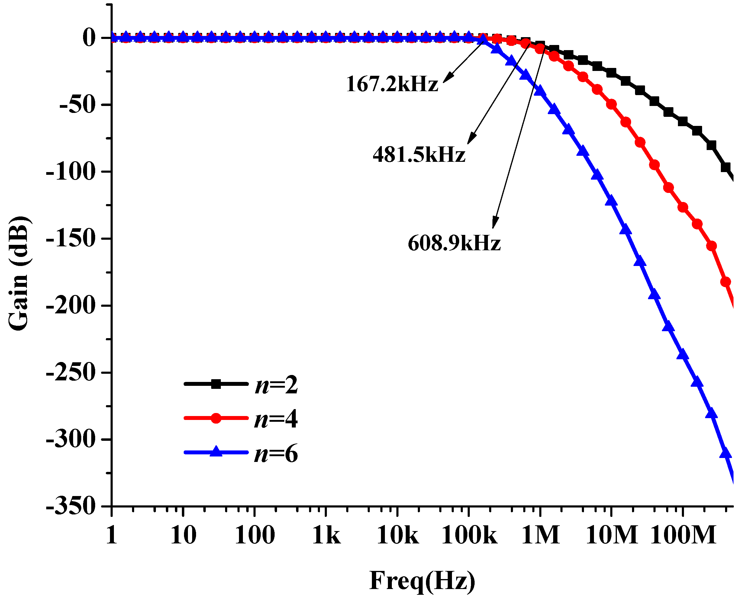
The amplitude-frequency responses of the LPF with different orders n (2, 4, and 6) is simulated and shown in Figure 4. It verifies that the attenuation increases with orders n and the attenuation of the fourth-order LPF is sufficient.
In order to optimally adapt to the multiple data rate standards, the LPF should be programmable. The digitally controlled resistor array shown in Figure 5 is used to adjust the cutoff frequencies of the LPF. It should be noted that the above-mentioned simulations are based on the Spectre simulator.
3. Measurement Results
The low-pass filter is designed and fabricated in standard 0.18 μm CMOS technology from the SMIC foundry, with a die area of 0.17 mm2. Due to the widely used differential circuits and architectures in the presented LPF, the layout symmetry should be guaranteed as much as possible. Although due to the lower operating frequencies, the effects from the stray capacitance are not serious, the layout is also optimized in order to reduce the stray capacitance and resistance. The chip is measured with an encapsulated chip-on-board from a voltage supply of 1.8 V. The photographs of the bonded chip and the testing board for the LPF are given in Figure 6, respectively.
In order to explore the performance of the LPF, the time-domain and frequency-domain measurement configurations are established respectively. The time-domain measurement platform is mainly made up of the RIGOL DP1308A power supply, the Anritsu MG3710A signal generator, and the Agilent DSO1024A oscilloscope. The frequency-domain measurement platform is basically composed of the DP1308A programmable DC power supply and the Agilent E5071C network analyzer.
Two single-tone signals with peak-to-peak amplitudes of 100 mV and frequencies of 1 MHz and 5 MHz are applied to the LPF with the cutoff frequency of 1.68 MHz, respectively. The two corresponding output waveforms with distinct different amplitudes of 102 mVpp @1MHz and 28 mVpp @5MHz are given in Figure 7. Therefore, it can be easily concluded that the passband and stopband of the LPF can function normally.
The measured amplitude-frequency responses with different bandwidths for the LPF are shown in Figure 8. It can be observed that the LPF exhibits smoother passbands with sharp attenuation, programmable cutoff frequencies of 605 kHz, 870 kHz, 1.02 MHz, 1.33 MHz, 1.53 MHz, and 2.15 MHz respectively, and over 50 dB attenuation at the frequencies which are ten times the cutoff frequencies. The comparison between the measured and simulated results of the filter with the lowest bandwidth setting is shown in Figure 9. It can be easily observed that the measured passband gain is slightly reduced, and the measured bandwidth is increased by about 120 kHz compared with its simulated counterpart. The reason for the deviation is the inaccuracy of the used device models.
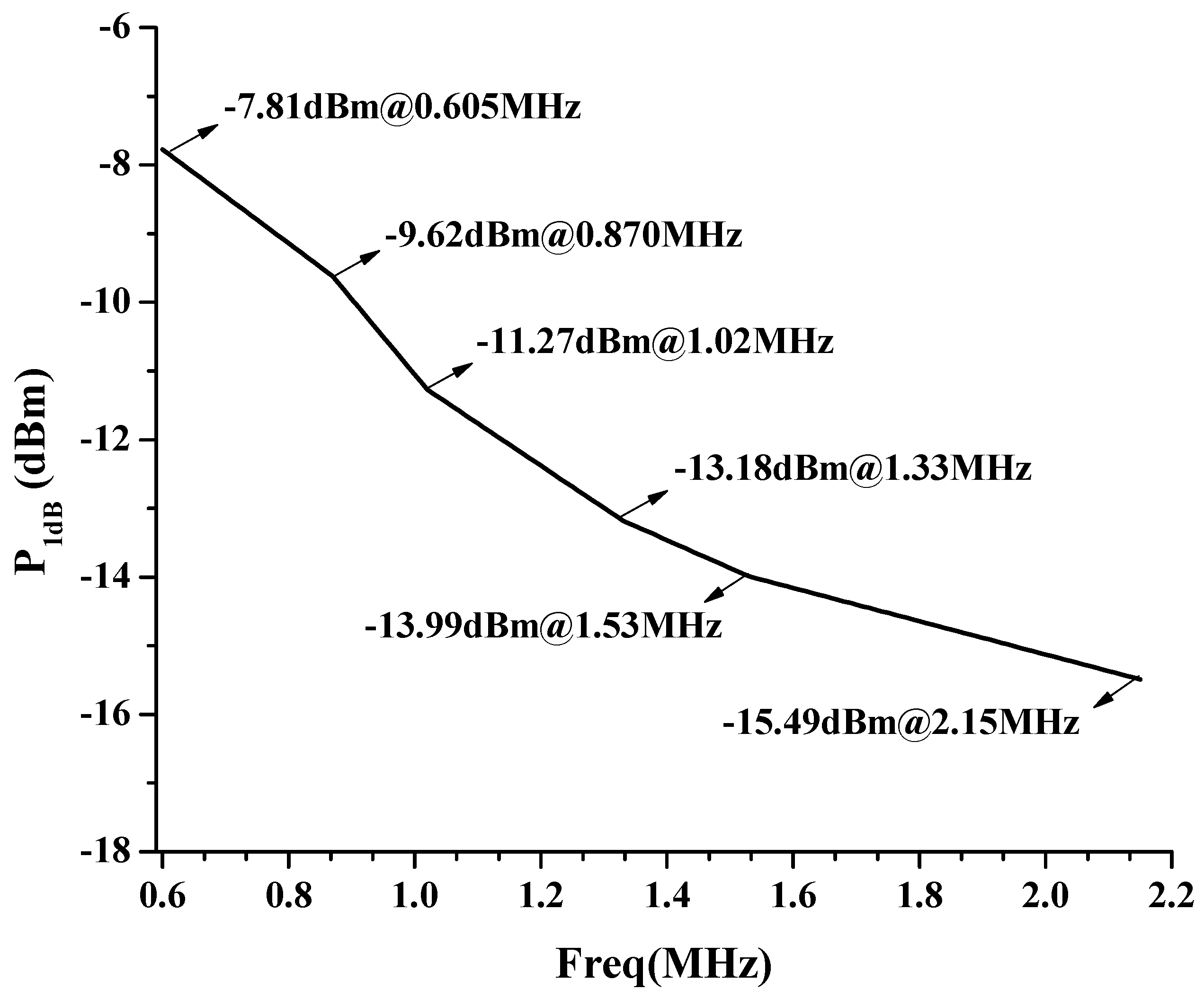
The measured input 1 dB compression point (P1dB) with different bandwidths for the LPF is given in Figure 10. It can be seen that the optimum input P1dB of the low-pass filter reaches −7.81 dBm.
In order to evaluate comprehensively a LPF, the figure of merit (FOM) is defined as follows [20]:
where fc, ATT, Pdiss and Adie represent the cutoff frequency, the attenuation at 10fc, the power consumption and die area, respectively.
The performance summary of the presented LPF and comparison with other prior arts are given in Table 1. It can be seen that the presented fourth-order filter achieves a smaller chip area and lower power consumption, and then the most excellent FOM among these filters of the same process and supply voltage. By contrast, it operates under lower frequencies due to the requirements from the targeted applications.
4. Conclusions
A programmable fourth-order Butterworth active-RC low-pass filter is presented in standard 0.18 μm CMOS technology. Two fully-differential Tow-Thomas biquads with two-stage fully-differential OPAs are employed for the LPF. Simulated results show the LPF achieves the desired performance.
Author Contributions
Conceptualization and methodology, C.Z. and L.S.; writing—original draft preparation, C.Z., L.S. and Y.W.; writing—review and editing, C.Z. and L.T.; visualization, Y.W.; supervision, C.Z.; project administration, C.Z.; funding acquisition, C.Z. and L.T. All authors have read and agreed to the published version of the manuscript.
Funding
This work was supported by the Natural Science Foundation of China (Nos. 61604082, 61674036) and the 14th “Six Talent Peaks” Project of Jiangsu Province (No. XYDXX-080).
Conflicts of Interest
The authors declare no conflict of interest.
References
- Bhattacharyya, M.; Gruenwald, W.; Jansen, D.; Reindl, L.; Aghassi-Hagmann, J. An Ultra-Low-Power RFID/NFC Frontend IC Using 0.18 μm CMOS Technology for Passive Tag Applications. Sensors. 2018, 18, 1452. [Google Scholar] [CrossRef] [PubMed] [Green Version]
- Scherhaufl, M.; Pichler, M.; Stelzer, A. UHF RFID Localization Based on Phase Evaluation of Passive Tag Arrays. IEEE Trans. Instrum. Meas. 2015, 64, 913–922. [Google Scholar] [CrossRef]
- Ghahremani, A.; Rezaei, V.D.; Bakhtiar, M.S. A UHF-RFID Transceiver with a Blocker-Canceller Feedback and +30 dBm Output Power. IEEE Trans. Circuits Syst. I Regul. Pap. 2013, 60, 3043–3054. [Google Scholar] [CrossRef]
- Kipnis, I.; Chiu, S.; Loyer, M.; Carrigan, J.; Rapp, J.; Johansson, P.; Westberg, D.; Johansson, J. A 900MHz UHF RFID Reader Transceiver IC. In Proceedings of the IEEE International Solid-State Circuits Conference, San Francisco, CA, USA, 11–15 February 2007; pp. 214–598. [Google Scholar] [CrossRef]
- Phan, A.T.; Farrell, R.; Lee, J.; Lee, S.-G. 380 MHz low-power sharp-rejection active-RC LPF for IEEE 802.15.4a UWB WPAN. In Proceedings of the IEEE International Symposium on Circuits and Systems, Taipei, Taiwan, 24–27 May 2009; pp. 1369–1372. [Google Scholar] [CrossRef] [Green Version]
- Li, S.; Chen, L.; Zhao, Y. Reconfigurable Active-RC LPF with Self-Adaptive Bandwidth Calibration for Software-Defined Radio in 130 nm CMOS. In Proceedings of the 2018 14th IEEE International Conference on Solid-State and Integrated Circuit Technology (ICSICT), Qingdao, China, 31 October–3 November 2018; pp. 1–3. [Google Scholar] [CrossRef]
- Duan, L.; Chen, G.; Ma, R.; Cao, M.; Chi, B. A Highly Linear 0.9V 3rd-Order Acitve-RC Low-Pass Filter in 28nm CMOS. In Proceedings of the 2019 IEEE International Conference on Electron Devices and Solid-State Circuits (EDSSC), Xi’an, China, 12–14 June 2019; pp. 1–2. [Google Scholar] [CrossRef]
- Ye, L.; Shi, C.; Liao, H.; Huang, R.; Wang, Y. Highly Power-Efficient Active-RC Filters with Wide Bandwidth-Range Using Low-Gain Push-Pull Opamps. IEEE Trans. Circuits Syst. I Regul. Pap. 2013, 60, 95–107. [Google Scholar] [CrossRef]
- Wu, W.; Mo, T.; Lu, Z. A 180nm CMOS three stage feedforward compensation op-amp with linearity improvement technique for active RC LPF. In Proceedings of the 2016 10th IEEE International Conference on Anti-counterfeiting, Security, and Identification (ASID), Xiamen, China, 23–25 September 2016; pp. 91–95. [Google Scholar] [CrossRef]
- Jin, X.; Dai, F.F.; Xin, J. A 6th order zero capacitor spread 1MHz-10MHz tunable CMOS active-RC low pass filter with fast tuning scheme. In Proceedings of the IEEE International Symposium on Circuits and Systems (ISCAS), Seoul, South Korea, 20–23 May 2012; pp. 1187–1190. [Google Scholar] [CrossRef]
- Li, Y.; Wang, Y. A 5th-Order Butterworth Active-RC Complex Band-pass Filter with New Passive Compensation. In Proceedings of the 2018 14th IEEE International Conference on Solid-State and Integrated Circuit Technology (ICSICT), Qingdao, China, 31 October–3 November 2018; pp. 1–3. [Google Scholar] [CrossRef]
- Laouej, D.; Daoud, H.; Loulou, M. Design of sixth order butterworth Gm-C filter using Particle Swarm Optimization program for biomedical application. In Proceedings of the 29th International Conference on Microelectronics (ICM), Beirut, Lebanon, 10–13 December 2017; pp. 1–5. [Google Scholar] [CrossRef]
- Meghdadi, M.; Bakhtiar, M. Analysis and Optimization of SFDR in Differential Active-RC Filters. IEEE Trans. Circuits Syst. I Regul. Pap. 2012, 59, 1168–1177. [Google Scholar] [CrossRef]
- Filanovsky, I.M. Filters with monotonic amplitude-frequency response. In Proceedings of the 1998 Midwest Symposium on Circuits and Systems, Notre Dame, IN, USA, 9–12 August 1998; pp. 436–439. [Google Scholar] [CrossRef]
- Kamat, D.V.; Mohan, P.V.A.; Prabhu, K.G. Active-RC filters using two-stage OTAs with and without feed-forward compensation. IET Circuits Devices Syst. 2011, 5, 527–535. [Google Scholar] [CrossRef]
- Zheng, H.; Luong, H.C. A 36/44 MHz Switched-capacitor Bandpass Filter for Cable-TV Tuner Application. In Proceedings of the 2006 IEEE Asian Solid-State Circuits Conference, Hangzhou, China, 13–15 November 2006; pp. 235–238. [Google Scholar] [CrossRef]
- Ravindran, A.; Savla, A.; Younus, I.; Ismail, M. A 0.8V CMOS filter based on a novel low voltage operational transresistance amplifier. In Proceedings of the 45th Midwest Symposium on Circuits and Systems, Tulsa, OK, USA, 4–7 August 2002; Volume III. [Google Scholar] [CrossRef]
- Mahattanakul, J.; Chutichatuporn, J. Design Procedure for Two-Stage CMOS Opamp with Flexible Noise-Power Balancing Scheme. IEEE Trans. Circuits Syst. I Regul. Pap. 2005, 52, 1508–1514. [Google Scholar] [CrossRef]
- Wang, W.; Yan, N.; Min, H. A wide tuning range Active-RC filter for multi-mode applications. In Proceedings of the 10th IEEE International Conference on Solid-State and Integrated Circuit Technology, Shanghai, China, 1–4 November 2010; pp. 336–338. [Google Scholar] [CrossRef]
- Huang, J.; Wen, J.; Lai, Y.; Liu, R. Chip design of an 8 MHz CMOS switched-capacitor low-pass filter for signal receiver applications. In Proceedings of the 2010 3rd International Congress on Image and Signal Processing, Yantai, China, 16–18 October 2010; pp. 4037–4041. [Google Scholar] [CrossRef]
- Hori, S.; Maeda, T.; Yano, H. A widely tunable CMOS Gm-C filter with a negative source degeneration resistor transconductor. In Proceedings of the 29th European Solid-State Circuits Conference, Estoril, Portugal, 16–18 September 2003; pp. 449–452. [Google Scholar] [CrossRef]
- Chen, G.; Li, Z.; Su, H.; Zhang, L.; Li, W. A 5th-order Chebyshev active RC complex filter with automatic frequency tuning for wireless sensor networks application. In Proceedings of the International Symposium on Signals, Systems and Electronics, Nanjing, China, 17–20 September 2010; pp. 1–4. [Google Scholar] [CrossRef]
- Huang, J.; Wen, J.; Lin, Y. Chip design of a 10-MHz switched capacitor low-pass filter for wireless application. In Proceedings of the 2014 Sixth International Conference on Wireless Communications and Signal Processing (WCSP), Hefei, China, 23–25 October 2014; pp. 1–5. [Google Scholar] [CrossRef]
Figure 1.
Schematic diagram of the presented LPF based on the Tow-Thomas biquads.
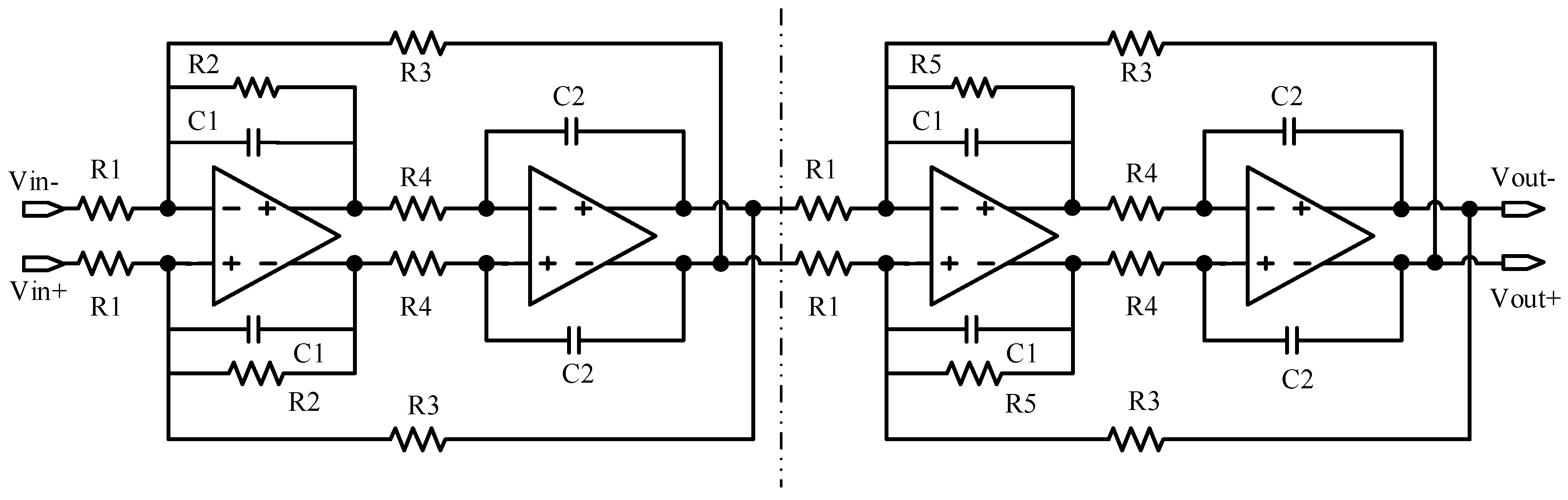
Figure 2.
Schematic diagram of the two-stage operational amplifier.
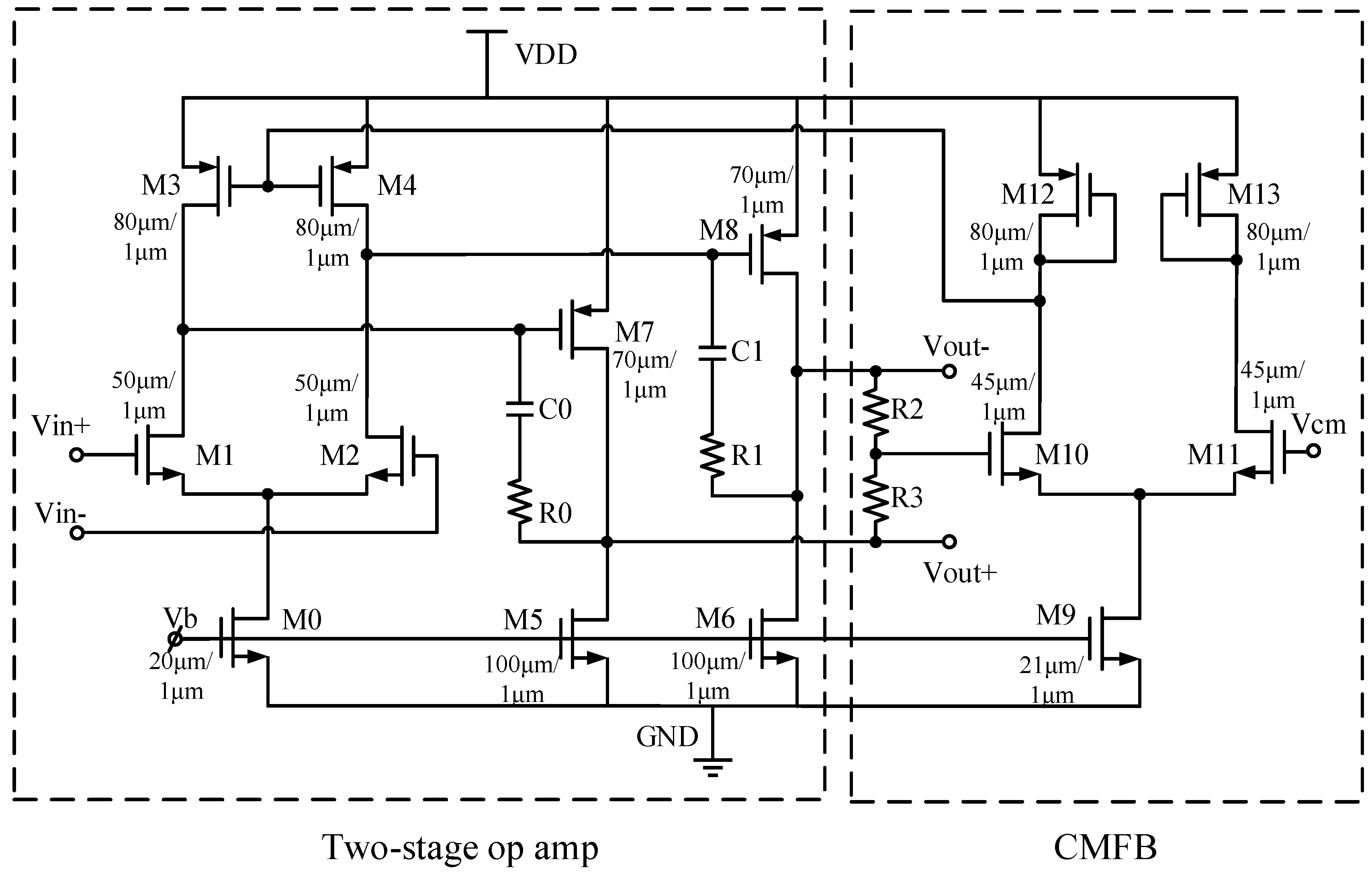
Figure 3.
Simulated frequency responses of the OPA under process conditions (TT, SS, and FF).

Figure 4.
Simulated amplitude-frequency responses of the LPF with different orders.

Figure 5.
Schematic diagram of the digital controlled resistor array.

Figure 6.
Measurement photographs: (a) bonded chip and (b) testing board.

Figure 7.
Measured time-domain responses with two single-tone input signals with amplitudes of 100 mVpp and frequencies of (a) 1 MHz and (b) 5 MHz respectively.
Figure 7.
Measured time-domain responses with two single-tone input signals with amplitudes of 100 mVpp and frequencies of (a) 1 MHz and (b) 5 MHz respectively.

Figure 8.
Measured amplitude-frequency responses with different bandwidths.
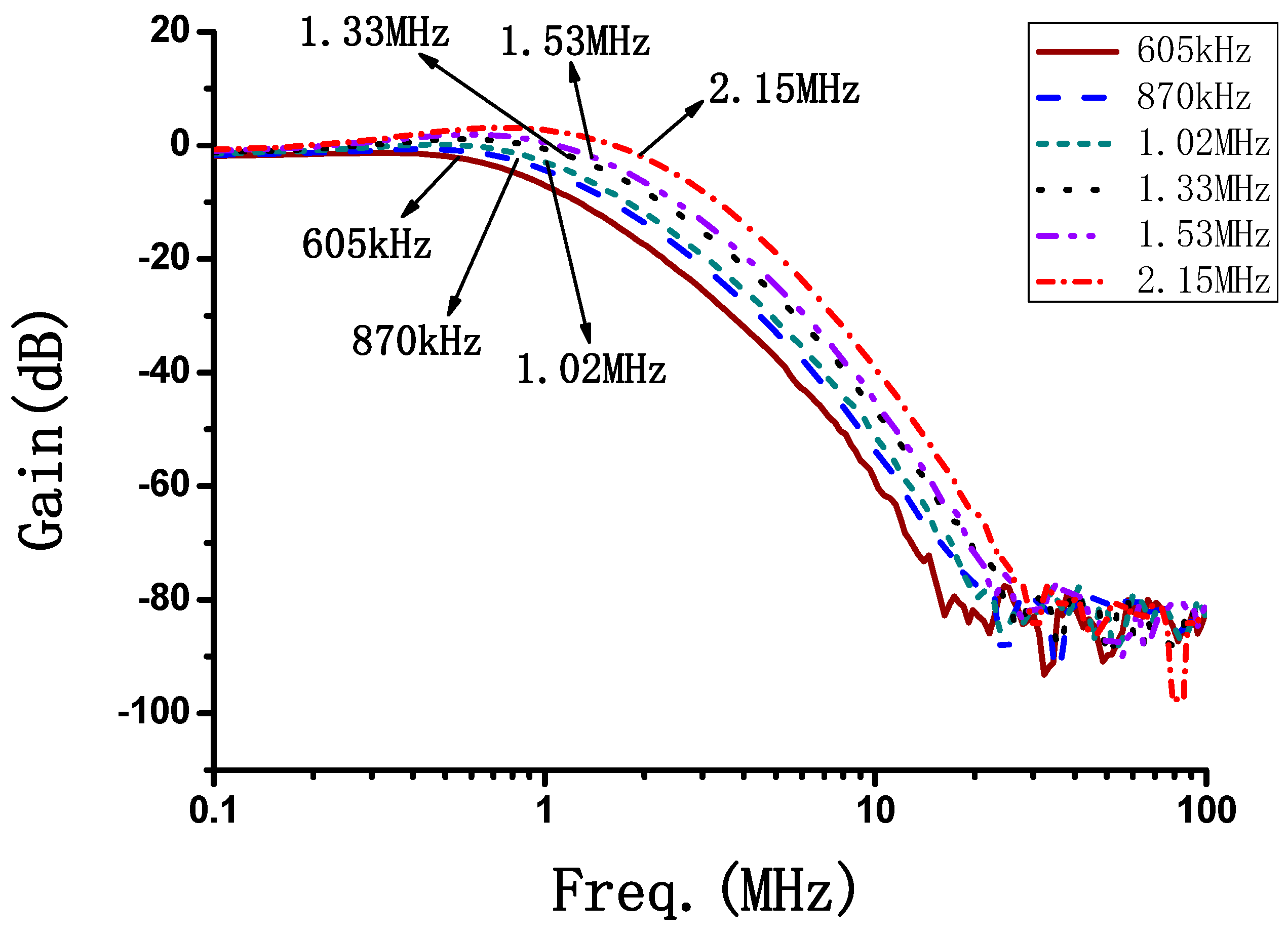
Figure 9.
Comparison between the measurement and simulation results.

Figure 10.
Measured input P1dB versus different bandwidths.

Table 1.
Performance summary and comparison with other prior arts.
| Ref. | [21] | [22] | [23] | [20] | This Work |
|---|---|---|---|---|---|
| Tech./nm | 180 | 180 | 180 | 180 | 180 |
| Supply(V) | 1.8 | 1.8 | 1.8 | 1.8 | 1.8 |
| Filter order | 6 | 5 | 5 | 5 | 4 |
| Power(mW) | 15 | 11.7 | 18 | 44.2 | 12.6 |
| fc(MHz) | 1.5—12 | 0.52—3 | 10.2 | 8.72 | 0.605—2.15 |
| Area(mm2) | 0.83 | 0.85 | 0.41 | 0.90 | 0.17 |
| Atte@10 fc | 60 | 56 | 35 | 40 | 70 |
| Input-referred noise(nV/√Hz) | / | / | / | 56—146 | 9—206 |
| FOM(dB) | 17.6 | 12.2 | 16.8 | 9.45 | 18.5 |
© 2020 by the authors. Licensee MDPI, Basel, Switzerland. This article is an open access article distributed under the terms and conditions of the Creative Commons Attribution (CC BY) license (http://creativecommons.org/licenses/by/4.0/).
Share and Cite
MDPI and ACS Style
Zhang, C.; Shang, L.; Wang, Y.; Tang, L. A CMOS Programmable Fourth-Order Butterworth Active-RC Low-Pass Filter. Electronics 2020, 9, 204. https://doi.org/10.3390/electronics9020204
AMA Style
Zhang C, Shang L, Wang Y, Tang L. A CMOS Programmable Fourth-Order Butterworth Active-RC Low-Pass Filter. Electronics. 2020; 9(2):204. https://doi.org/10.3390/electronics9020204
Chicago/Turabian StyleZhang, Changchun, Long Shang, Yongkai Wang, and Lu Tang. 2020. "A CMOS Programmable Fourth-Order Butterworth Active-RC Low-Pass Filter" Electronics 9, no. 2: 204. https://doi.org/10.3390/electronics9020204
Note that from the first issue of 2016, this journal uses article numbers instead of page numbers. See further details here.