Passive Current Control Design for MMC in HVDC Systems through Energy Reshaping


1
Department of Electrical Engineering and Electronics, University of Liverpool, Liverpool L69 3GJ, UK
2
Faculty of Electric Power Engineering, Kunming University of Science and Technology, Kunming 650500, China
3
College of Electric Power, South China University of Technology, Guangzhou 510640, China
*
Author to whom correspondence should be addressed.
Electronics 2019, 8(9), 967; https://doi.org/10.3390/electronics8090967
Submission received: 15 August 2019
/
Revised: 28 August 2019
/
Accepted: 30 August 2019
/
Published: 30 August 2019
(This article belongs to the Special Issue Modeling and Control of Power Electronic Converters in Renewable Energy and Smart Grid Systems)
Abstract
:The complexity of the internal dynamics of a modular multi-level converter (MMC) has raised severe issues for designing corresponding controllers. The existing MMC cascaded control strategies, based on classical linear control theory, require a relatively complex structure to achieve control objectives and the parameter tuning processes during the corresponding controller design are normally difficult to solve for the highly non-linear systems with highly coupled states in MMC. On account of this, advanced controllers are required for the regulation tasks of MMC. Passivity is introduced into the MMC control system by the passive control (PC) proposed in this paper. PC can provide an extra damping effect to help save energy through utilizing passivity in the system. A controllable de-coupled form is achieved by passivation of the output calculation. Hence, well-tuned controllers can be designed and employed to effectively regulate the output current and inner differential currents of the MMC under system operating point variation. Simulation results yield numerical data that show significantly improved steady-state and transient-state performances with greatly reduced control costs.
1. Introduction
The modular multi-level converter (MMC) has been regarded as the most prominent converter topology for voltage source converter-based high voltage direct current (VSC-HVDC) systems, due to its high efficiency, modular design, scalability (in terms of voltage and power), low distortion of the output voltage, and minimized filter design [1,2]. As a result of the widespread application of VSC in renewable energy generation [3], especially in permanent magnet synchronous generator (PMSG)-based [4] and double fed induction generator (DFIG)-based [5] wind farms and energy storage systems [6], MMC has become one of the most essential power-electronics devices in modern power systems. The overall MMC control system has expanded the MMC design complexity from its topological configuration in power electronics. Consequently, the design of corresponding MMC control systems has drawn considerate research interest recently [7,8]. A number of control strategies [9,10] based on classical linear control theory have been applied to MMC systems, such as proportional-integral (PI) and proportional-resonant (PR) controllers. However, more advanced control strategies are required, due to the highly non-linear dynamics of MMC, with a wide range of operational points and strong coupling among states [11,12]. In addition, the design process of multi-resonant and repetitive linear controllers, especially the parameter tuning process, is too difficult to conduct manually [7,13].
Recently, researchers have presented various model predictive control (MPC)-based control methods, utilizing both direct and indirect model-based predictive control [14,15,16]. However, the high-level model complexity of MMC and the corresponding number of sub-modules (SMs) results in a greatly increased computational burden for MMC digital controllers. Hence, the implementation of MPC-based methods in real time is hindered by their substantial calculation requirements, especially in MMC applications with a large number of voltage levels. Global control consistency can be provided by feedback linearization based control strategy utilizing full non-linearity compensation, which has been shown to be suitable for acquiring both excellent control performance and system stability in MMC systems [7].
The non-linear feedback designs mentioned can not consider the characteristics of investigated systems which have inherent physical properties and corresponding energy-dissipative natures. From a practical point of view, a energy-based non-linear control law is required to fully utilize these intrinsic physical features of complex system characteristics for stabilization and command tracking [17,18]. Passive control (PC), also called Passivity-based control (PBC), theory provides a useful method for systematically analyzing the fundamental physical features in engineering problems. A general dynamical system is regarded as an energy transmission system, where the controller is treated as another energy interconnection system, which reshapes the overall energy of the target system. Hence, a desirable closed-loop system behaviour can be achieved. Linear input–output behavior of the MMC internal dynamics can also be achieved by performing a passivation, while order reduction of the internal dynamics can be realized, in contrast to regarding currents or capacitor voltages as outputs [19]. Therefore, PC introduces robustness to ’energy-preserving’ (i.e., passive) unmodeled effects and enhanced system damping performance, as compared with existing model-based non-linear controllers [17].
This paper proposed a PC-based controller, which has already been successfully implemented in various industrial applications, such as induction motors [20], robot arms [17], and low-voltage/medium-voltage DC-DC converters [21,22]. The proposed PC, compared to the other existing control theories, offers a satisfactory dynamic response and steady-state performance, since it can provide globally consistent control performance with extra damping effects through passivation. Satisfactory dynamic response is an essential requirement for the flexible application of MMC-based VSC-HVDC systems, such as renewable energy source integration. Satisfactory dynamic response is also required to provide the guaranteed stable operation of MMC-based VSC-HVDC systems in power systems under different conditions, especially under fault conditions. Simulation studies in the Simulink software environment are implemented to verify the performance and effectiveness of the proposed PC control strategy in an MMC-based VSC-HVDC system.
2. State Functional Model of the MMC
In this paper, the proposed passive current control strategy is applied and demonstrated in a typical MMC system, shown in Figure 1.
An MMC consists of N SMs per arm and may contain M redundant SMs per arm. The SMs are connected in series, in each arm. In practical applications, normally 10% redundant SMs are used for reliability improvement [23]; however, in this chapter, . An arm inductor is installed in each arm to limit the arm currents in events such as a DC short circuit. Each arm is equipped with an equivalent resistor to represent the losses of the circuit elements in each arm, such as the power semiconductors, with equivalent series resistance in and .
Assuming the SM capacitor voltages are balanced in each system arm, the voltages of the upper () and lower () arms can be expressed as follows:
The current through the upper and lower arms can be expressed, respectively, as follows:
where and denote the average capacitor voltage in the upper arm and lower arms, respectively; denotes the normalized output voltage reference signal; denotes the normalized differential voltage reference signal; denotes the output current of the MMC; denotes the inner differential current; and the output voltage of the MMC is expressed as:
where and are the equivalent voltage source of the load and the equivalent inductor connected to the the middle points of the two arms of the MMC, respectively. The DC voltage can be expressed as follows:
According the equations mentioned above, and can be controlled by adjusting and . The current which flows through each arm will charge and discharge the corresponding SM capacitors, and the following relationships can be derived:
where the and represent the number of SMs inserted in upper and lower arms, respectively, which are the actual control inputs for the MMC [7]. Hence, the state functions of the MMC system can be obtained, where the state variables are chosen as and . The inputs of the system are chosen as and the outputs of the system are chosen as . The state functions of the MMC system can be expressed as follows:
where
3. PC Design for the MMC
3.1. Passive Control with Energy-Reshaping
Consider a normal system as follows
where the output is and control input is , such that considered system (12) is of vector relative degree of one, is considered as being non-linear and consists of the structure with parameter uncertainties, is the time-varying external disturbance, and is a known smooth function of dimension . The unknown control gain is written as
The energy balance equations of the system can be considered as
where is the stored energy function and and are non-negative functions that represent the energy dissipation (such as circuit resistances). The system is defined to have output strictly passive if there exists a continuously differentiable positive semi-definite function , called the storage function, such that
where . The following lemma is required for achieving asymptotic stability . It is assumed that the zero-state of system (12) is detectable and its minimum-phase is locally weak. Hence, the uncontrolled system has an asymptotically stable origin and a positive definite storage function [24]. In addition, the origin of the system will be globally asymptotic stable if the system has a radially unbounded storage function [25].
As illustrated in Figure 2, the controller is regarded as a one-port system which is coupled with the plant , which needs to be controlled by a two-port interconnection subsystem . Hence, in terms of passivity, interconnection of the controller and plant is obvious, as illustrated below. Further detailed considerations of PC can be found in the literature [24,25] .
3.2. Proposed Passive Current Control in MMC
To introduce passivity into the MMC control, calculating the passive output y is necessary (considering the passivity theory):
where are the corresponding reference signals of x and is derived from , which removes the effects of dissipation and supplies and is expressed as
The proposed current controller for system using passivation is designed as
where
where and are the feedback control gains, which place the poles of the closed-loop system in the left-half plane (LHP) and are tuned for system global stability for all operation points. , where is the internal Electromotive Force (EMF) voltage of the MMC.
The whole proposed MMC current control system is illustrated in Figure 3.
As, in the whole MMC operation range, , where ≍ is the asymptotic symbol, the feedback passivation law transforms the non-linear system into a linear one with a decoupled relation. We choose the new system output as Let , where and are some positive constants for the feedback passivation to inject an extra damping and . According to the relations mentioned in the last section, the storage function can be constructed by:
Differentiating with respect to time, we get
According to a typical linear PR controller design adopted in MMC system shown below,
where and are the proportional and resonant gains, respectively; and are the resonant cut-off frequency and the fundamental angular frequency, respectively; and and are the proportional and integral gains, respectively. Therefore, the linear PR controller can efficiently regulate the output current and the linear PI controller can efficiently regulate the differential current.
Therefore, the storage function can be derived as:
It is obvious that the zero-state of the uncontrolled system is detectable. The MMC system is regarded as strictly passive from output Y to input V [18]. As the upper-level output power commands provide instruction to the reference output current , the inner differential current reference is achieved through the SM capacitor voltage control and the balancing active power process. From the relationship mentioned previously, one can conclude that and are asymptotically stabilized to their expected signals.
The canonical form of a typical closed-loop system is represented in the following Figure 4:
A closed-loop system in control theory is regarded as a feedback control system. It provides one typical control system concept which, on the basis of an open-loop system, a forward path is used. However, it has one or more feedback loops for connecting its output and its input.
Closed-loop systems are utilized to obtain the required output signal R(s) by comparison with the actual plant signal C(s). An error signal E(s) is generated to express the difference between the output and the desired signal. In other words, a “closed-loop system” is a fully self-excited control system.
The transfer function is calculated as follows: . In order to study the feedback passivation gains and in the MMC system and analyze the corresponding performance, the closed-loop system can be given as follows:
According to the closed-loop system of the MMC, the poles can be derived and are located at and -. Faster error convergence can be achieved by using larger and . The transfer function of the closed-loop system can be written as follows:
Hence, the bandwidth of proposed controller can be given as follows:
3.3. Internal Dynamics Stability
Under the proposed PC, the relative degree of MMC system ( and ) is , which is less than the dimension of total system (). There is an obvious dimensional subsystem containing two internal dynamics ( and ), which can been seen in Figure 3, that are not observable from the outputs. These unobservable leftover dynamics may cause overall system instability. Thus, analytical verification of the internal dynamics stability is required. The two internal dynamics ( and ) can be expressed as in Equation (6) and as follows:
As the system output tracking errors are expected to identically approach zero, the behaviour of system is governed by the aforementioned differential equation, and the two internal dynamics ( and ) are called the zero dynamics. Meanwhile, , , and can be expressed as:
where and are the amplitudes of and , respectively; is the fundamental angular frequency; and is the phase displacement between and . The voltage ripples on the SM capacitors are neglected in this analysis. Then, and in the expression of can be expressed as follows;
where is the DC component in , which balances the input and output power of the MMC, and is the output of the differential voltage controller, which eliminates the voltage difference between the upper and lower arms. A simple proportional controller with gain K is assumed for the differential voltage control. Therefore, the DC components in the zero dynamics refer to the shifting of SM capacitor voltages, and the AC terms can be taken as ripples on the SM capacitor voltage. The DC terms can be expressed as follows, and are taken into consideration while analyzing the stability of the system zero dynamics.
There are two situations that need to be taken in consideration for the MMC zero dynamics stability analysis. First, , the phase trajectories of the zero dynamics, which are illustrated in Figure 6. It can be seen that, if and are not equal, they will be forced to move toward each other and converge to a new balanced point (where ), with the help of the differential voltage controller. In Figure 6, it is also revealed that can be guaranteed at various operation points.
The phase trajectory diagram of the zero dynamics when SM capacitor voltage is equal to both and is depicted in Figure 7. It is shown that there are two equilibrium points. However, the smaller equilibrium point is unstable, whereas the larger equilibrium point is stable. This implies that, while applying the control law to the MMC system (1)–(3), the SM capacitor voltage of MMC system must come close to [26].
4. Case Studies
The proposed PC was applied to the MMC mentioned in the previous section. The control performance of the proposed PC strategy was evaluated under steady-state and external transient variation conditions and then compared to that of the conventional control and Feedback linearization control (FLC) used in [7]. The system parameters used in the simulation are listed in Table 1. Firstly, the MMC overall performance was evaluated under a step change of grid voltage at 0.096 s. As shown in the converter output three-phase voltage and current curves in Figure 8, Figure 9 and Figure 10, it can be seen that the proposed PC strategy, FLC, and conventional linear control strategies coudl all handle the transient step change of 0.1 per unit (p.u.) on the grid-side voltage. As also illustrated in Figure 8, Figure 9 and Figure 10, the MMC system operated well under the different control strategies and skipped to the new equilibrium point with an acceptable convergence speed. The difference of control performance among the three strategies was not very obvious and, so, required further analysis. For further investigation, enlarged MMC single-phase inner-output current and differential current curves were compared and evaluated among three control strategies in the following part.
For the MMC inner steady-state performance analysis, the MMC output current, output voltage, and both upper/lower arm current waveforms were investigated. The amplitude of the output current was maintained in the steady-state performance. The steady-state performance of the MMC regulated by the proposed PC is illustrated in Figure 11, which shows that the output currents were regulated effectively by applying the proposed PC strategy. The MMC also operated stably with the proposed PC strategy. It is noted that there was a nearly 90° phase difference between the MMC output voltage and current. This is because the MMC system worked as an inverter and operated in a capacitive mode for the MMC inner steady-state performance analysis. In other words, the MMC was injecting reactive power to the equivalent main power grid [27] during this case study.
As can be seen in Figure 12, the capacitor voltage was also well stabilized by the proposed PC strategy.
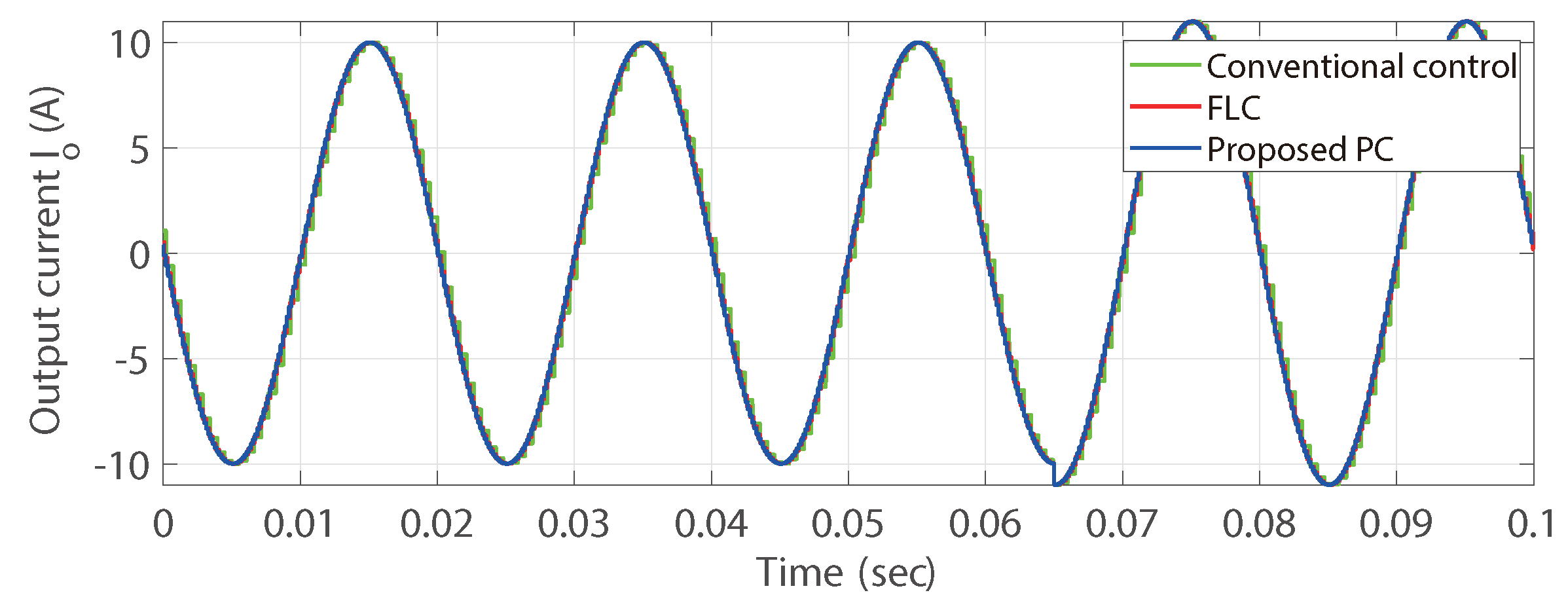
For comparison, the tracking errors of the output current signals of the MMC under the conventional linear control strategy, the FLC proposed in [7], and the proposed PC are shown in Figure 13. It is obvious that the FLC and PC were able to achieve almost the same excellent output current tracking accuracy (with peak-to-peak tracking error of less than 0.07 A) than that of the conventional control strategy, due to consideration of non-linearity. The high-frequency chatting error was easily introduced in the conventional control due to the high sampling frequency of the generated reference signals. The high-frequency chatting error seems to have caused a small impact on the overall system. However, it still had an accumulative influence on the MMC switching process, in the long-term. Therefore, by adopting a control strategy such as the proposed PC, the MMC high-frequency switching stress could be effectively relieved, potentially extending the life-cycle of the power electronics. For evaluating the dynamic response performance of the MMC, the amplitude of the reference current signal was raised by 10% at 0.065s. The waveforms of the output current, as regulated by different control strategies, are displayed in Figure 14. It can be seen that the dynamic responses obtained using the different control strategies were almost similar.
For further evaluation of the control performance of the different control strategies with numerical data, the absolute error index (IAE) was introduced. Here, , where is the reference value of the variable x. The simulation time was s. The results are presented in Table 2. Note that the proposed PC provided excellent performance, when compared with the conventional control and FLC methods, especially in suppressing unwanted fluctuations in differential currents. The IAE value of the proposed PC was only 51.1% of that in the conventional control, and it was 64.1% of that in the FLC method.
The overall control efforts of the different approaches could also be evaluated by IAE index, where . Numerical data is also provided in Table 2 and Table 3 and it was verified that the proposed PC could effectively reduce control efforts, compared with FLC (as proposed in [7]). The large effort savings (12.1% and 26.9%) compared with FLC resulted from the benefit of extra damping effects due to passivation in the proposed PC, instead of the full linearization used in FLC.
5. Conclusions
In this paper, a PC-based control strategy has been proposed and applied to an N-level MMC steady-state model for regulating internal dynamics. MMC is a well-proven technology for VSC-HVDC applications which has high non-linearity and strong coupling among its states. PC-based current control strategies provide an alternative for addressing the non-linear problem and decoupling the states of the system, in comparison with the FLC method proposed in [7]. The use of passivation in the controller can provide extra damping effects, compared to regulating under full system linearization. The proposed PC also considers global stability and does not need further tuning when the operating points vary. Simulation results and the corresponding analysis under steady-state conditions have verified the effectiveness of the proposed PC. In comparison, conventional control systems introduce the high-frequency chatting phenomenon and cause huge waste of control efforts, due to incomplete non-linearity compensation when operating points vary rapidly, especially when applyied to high sampling-resolution reference signals. FLC still wastes a considerable proportion of control efforts during the corresponding regulation process utilizing full linearization. The overall control efforts can be largely reduced by applying the proposed PC in MMC systems.
Author Contributions
Conceptualization, Y.S. and B.Y.; validation, Y.S. and H.S.; investigation, N.A. and F.Z.; methodology, T.Y. and H.S.; writing—original draft preparation, Y.S.; writing—review and editing, Y.S. and B.Y.; visualization, Y.S. and N.A.; supervision, T.Y. and H.S.; project administration, B.Y.; funding acquisition, B.Y.
Funding
This research was funded by National Natural Science Foundation of China grant number (51667010, 51777078).
Conflicts of Interest
The authors declare no conflict of interest.
References
- Martinez-Rodrigo, F.; Ramirez, D.; Rey-Boue, A.B.; De Pablo, S.; Herrero-de Lucas, L.C. Modular Multilevel Converters: Control and Applications. Energies 2017, 10, 1709. [Google Scholar] [CrossRef]
- Debnath, S.; Qin, J.; Bahrani, B.; Saeedifard, M.; Barbosa, P. Operation, control, and applications of the modular multilevel converter: A review. IEEE Trans. Power Electron. 2015, 30, 37–53. [Google Scholar] [CrossRef]
- Liao, S.W.; Yao, W.; Han, X.N.; Wen, J.Y.; Cheng, S.J. Chronological operation simulation framework for regional power system under high penetration of renewable energy using meteorological data. Appl. Energy 2017, 203, 816–828. [Google Scholar] [CrossRef]
- Chen, J.; Yao, W.; Zhang, C.K.; Ren, Y.; Jiang, L. Design of robust MPPT controller for grid-connected PMSG-Based wind turbine via perturbation observation based nonlinear adaptive control. Renew. Energy 2019, 134, 478–495. [Google Scholar] [CrossRef]
- Liu, J.; Yao, W.; Wen, J.Y.; Fang, J.K.; Jiang, L.; He, H.B.; Cheng, S.J. Impact of power grid strength and PLL parameters on stability of grid-connected DFIG wind farm. IEEE Trans. Sustain. Energy 2019. [Google Scholar] [CrossRef]
- Liu, J.; Wen, J.Y.; Yao, W.; Long, Y. Solution to short-term frequency response of wind farms by using energy storage systems. IET Renew. Power Gen. 2016, 10, 669–678. [Google Scholar] [CrossRef]
- Yang, S.; Wang, P.; Tang, Y. Feedback linearization-based current control strategy for modular multilevel converters. IEEE Trans. Power Electron. 2018, 33, 161–174. [Google Scholar] [CrossRef]
- Faisal, R.; Badal, P.D.; Subrata, K.; Sarker Sajal, K.D. A survey on control issues in renewable energy integration and microgrid. Prot. Control Mod. Power Syst. 2019, 4, 87–113. [Google Scholar]
- Tao, F.; Xie, Z.; Cheng, J.; Li, C.; Zhao, L.; Wen, J.Y. Fast valve power loss evaluation method for modular multi-level converter operating at high-frequency. Prot. Control Mod. Power Syst. 2016, 1, 21–32. [Google Scholar] [CrossRef]
- Rahman, H.; Xu, L.; Yao, L. Protection of large partitioned MTDC Networks Using DC-DC converters and circuit breakers. Prot. Control Mod. Power Syst. 2016, 1, 16–30. [Google Scholar] [CrossRef]
- Yang, B.; Yu, T.; Shu, H.C.; Dong, J.; Jiang, L. Robust sliding-mode control of wind energy conversion systems for optimal power extraction via nonlinear perturbation observers. Appl. Energy 2018, 210, 711–723. [Google Scholar] [CrossRef]
- Yang, B.; Jiang, L.; Wang, L.; Yao, W.; Wu, Q.H. Nonlinear maximum power point tracking control and modal analysis of DFIG based wind turbine. Int. J. Electr. Power Energy Syst. 2016, 74, 429–436. [Google Scholar] [CrossRef] [Green Version]
- Yang, B.; Zhang, X.S.; Yu, T.; Shu, H.C.; Fang, Z.H. Grouped grey wolf optimizer for maximum power point tracking of doubly-fed induction generator based wind turbine. Energy Convers. Manag. 2017, 133, 427–443. [Google Scholar] [CrossRef]
- Qin, J.; Saeedifard, M. Predictive control of a modular multilevel converter for a back-to-back HVDC system. IEEE Trans. Power Del. 2012, 2012 27, 1538–1547. [Google Scholar]
- Vatani, M.; Bahrani, B.; Saeedifard, M.; Hovd, M. Indirect finite control set model predictive control of modular multilevel converters. IEEE Trans. Smart Grid 2015, 6, 1520–1529. [Google Scholar] [CrossRef]
- Riar, B.S.; Geyer, T.; Madawala, U.K. Model predictive direct current control of modular multilevel converters: Modeling, analysis, and experimental evaluation. IEEE Trans. Power Electron. 2015, 30, 431–439. [Google Scholar] [CrossRef]
- Ortega, R.; Loria, A.; Nicklasson, P.J.; Sira-Ramirez, H. Passivity Based Control of Euler-Lagrange Systems; Springer: London, UK, 1998. [Google Scholar]
- Yang, B.; Yu, T.; Shu, H.C.; Zhang, Y.M.; Chen, J.; Sang, Y.Y.; Jiang, L. Passivity-based sliding-mode control design for optimal power extraction of a PMSG based variable speed wind turbine. Renew. Energy 2018, 119, 577–589. [Google Scholar] [CrossRef]
- Barnklau, H.; Gensior, A.; Rudolph, J. A model-based control scheme for modular multilevel converters. IEEE Trans. Ind. Electron. 2013, 60, 5359–5375. [Google Scholar] [CrossRef]
- Ortega, R.; Espinosa, G. Torque regulation of induction motors. Automatica 1993, 29, 621–633. [Google Scholar] [CrossRef]
- Sira-Ramirez, H.; Perez-Moreno, R.A.; Ortega, R.; Garcia-Esteban, M. Passivity-based controllers for the stabilization of DC-to-DC power converters. Automatica 1997, 33, 499–513. [Google Scholar] [CrossRef]
- Stankovic, A.M.; Perreault, D.J.; Sato, K. Synthesis of dissipative nonlinear controllers for series resonant DC/DC converters. IEEE Trans. Power Electron. 1999, 14, 673–682. [Google Scholar] [CrossRef]
- Saad, H.; Guillaud, X.; Mahseredjian, J.; Dennetiere, S.; Nguefeu, S. MMC capacitor voltage decoupling and balancing controls. IEEE Trans. Power Del. 2015, 30, 704–712. [Google Scholar]
- Ortega, R.; Schaft, A.; Mareels, I.; Maschke, B. Putting energy back in control. IEEE Control Syst. 2001, 21, 18–33. [Google Scholar]
- Ortega, R.; Schaf, A.; Castanos, F.; Astolfi, A. Control by interconnection and standard passivity-based control of port-Hamiltonian systems. Trans. Autom. Contr. 2008, 53, 2527–2542. [Google Scholar]
- He, L.; Zhang, K.; Xiong, J.; Fan, S. A repetitive control scheme for harmonic suppression of circulating current in modular multilevel converters. IEEE Trans. Power Electron. 2015, 30, 471–481. [Google Scholar] [CrossRef]
- Liu, Y.; Huang, A.Q.; Song, W.; Bhattacharya, S.; Tan, G. Small-signal model-based control strategy for balancing individual DC capacitor voltages in cascade multilevel inverter-based STATCOM. IEEE Trans. Ind. Electron. 2009, 56, 2259–2269. [Google Scholar] [CrossRef]
Figure 1.
(a) Three-phase modular multi-level converter (MMC) topology; (b) Half-bridge circuit for the ith SM.
Figure 1.
(a) Three-phase modular multi-level converter (MMC) topology; (b) Half-bridge circuit for the ith SM.

Figure 2.
Interconnection of controller and plant in terms of passivity.

Figure 3.
Block diagram of the proposed control system for the MMC system.
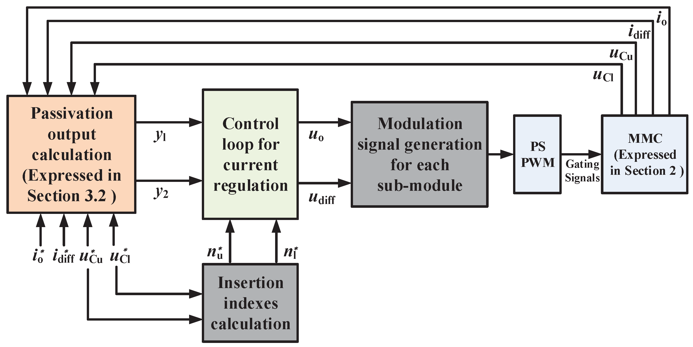
Figure 4.
Block diagram of the closed-loop system transfer function.
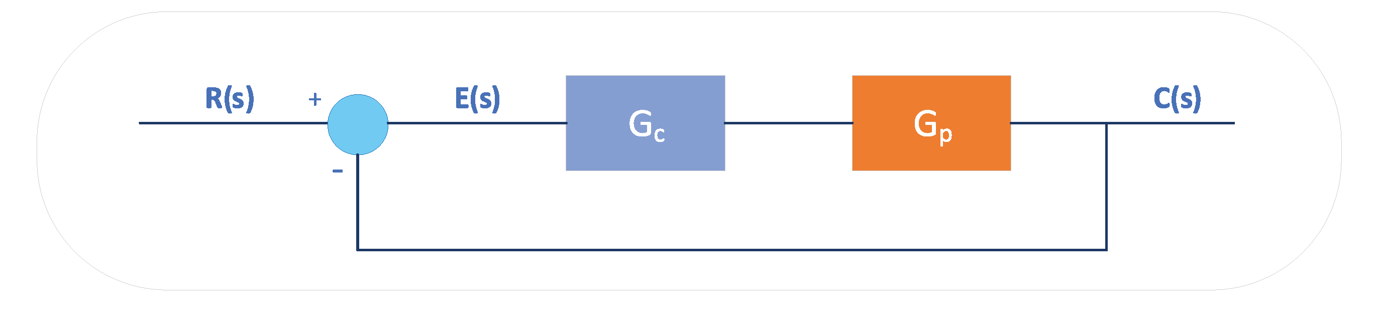
Figure 5.
Block diagram of the proposed control system for the MMC system.
Figure 6.
Phase trajectory of the zero dynamics when is not equal to .

Figure 7.
Phase trajectory of the zero dynamics when and are the same and equal to SM capacitor voltage .
Figure 7.
Phase trajectory of the zero dynamics when and are the same and equal to SM capacitor voltage .
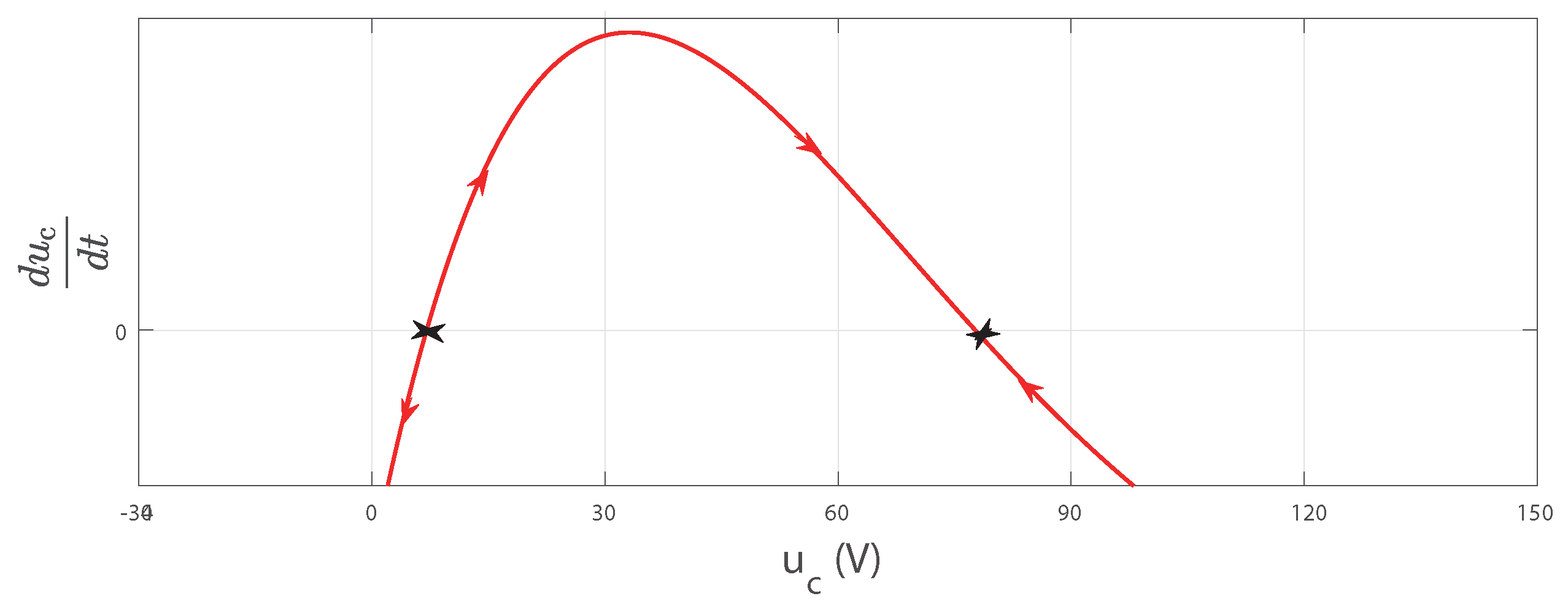
Figure 8.
Three-phase voltage and current waveforms on the MMC converter-side and grid-side with proposed PC.
Figure 8.
Three-phase voltage and current waveforms on the MMC converter-side and grid-side with proposed PC.
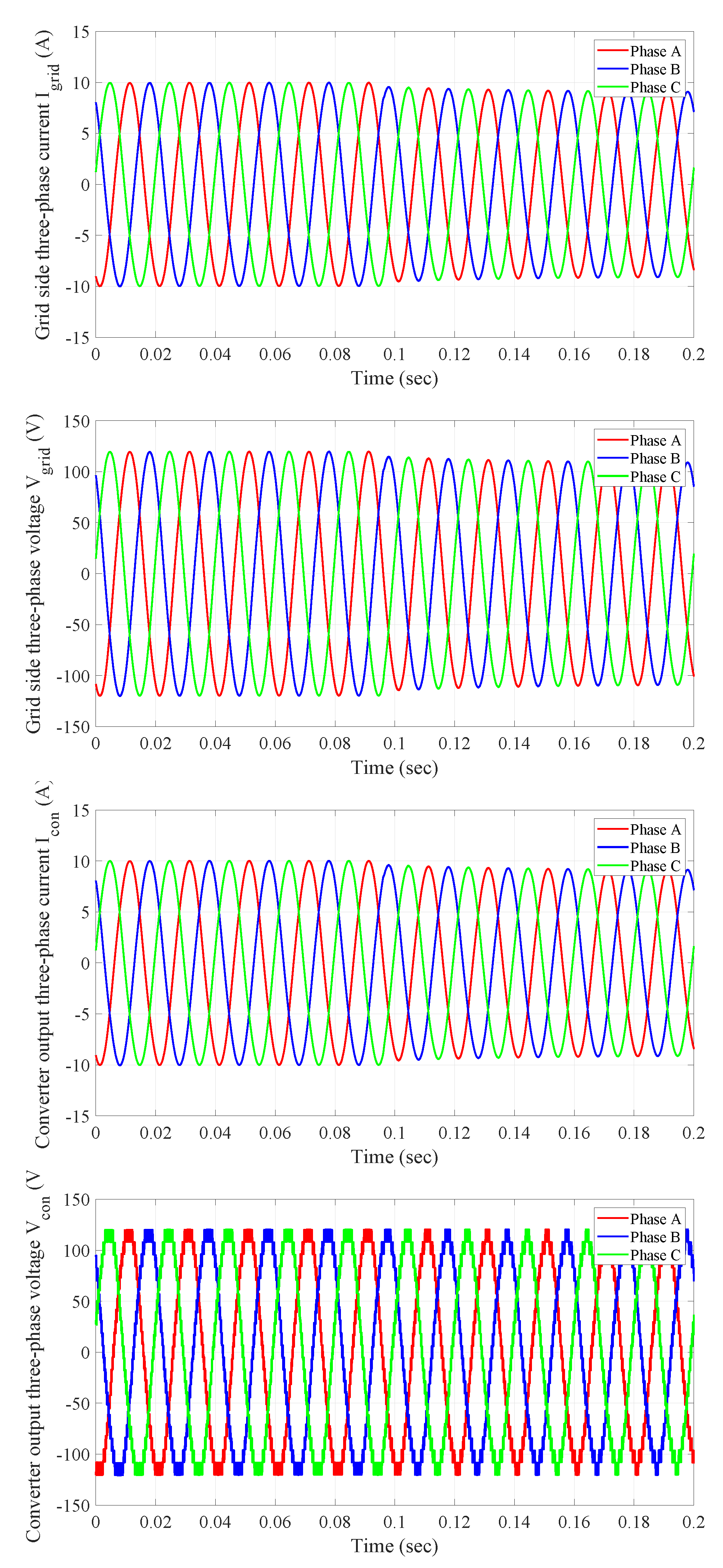
Figure 9.
Three-phase voltage and current waveforms on the MMC converter-side and grid-side with conventional control.
Figure 9.
Three-phase voltage and current waveforms on the MMC converter-side and grid-side with conventional control.
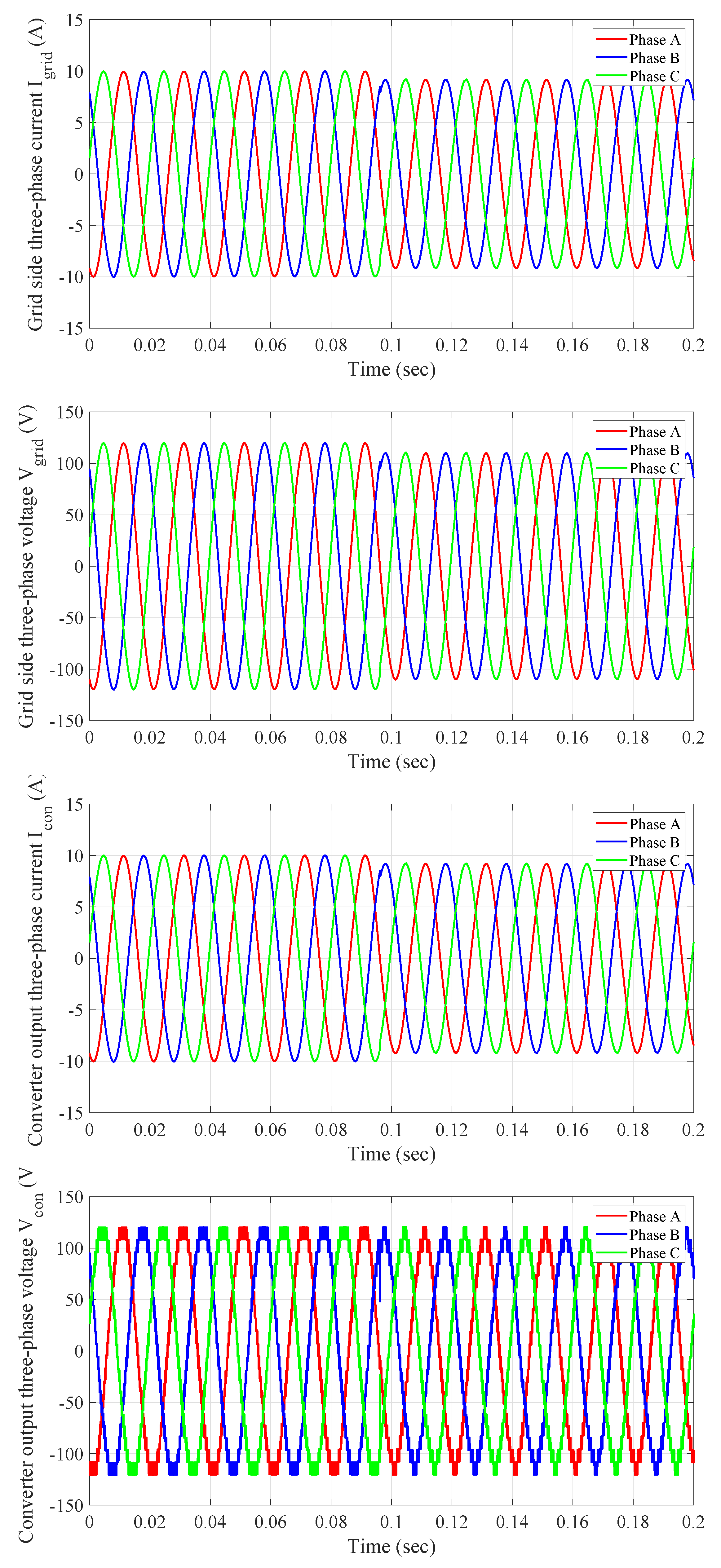
Figure 10.
Three-phase voltage and current waveforms on the MMC converter-side and grid-side with Feedback linearization control (FLC).
Figure 10.
Three-phase voltage and current waveforms on the MMC converter-side and grid-side with Feedback linearization control (FLC).
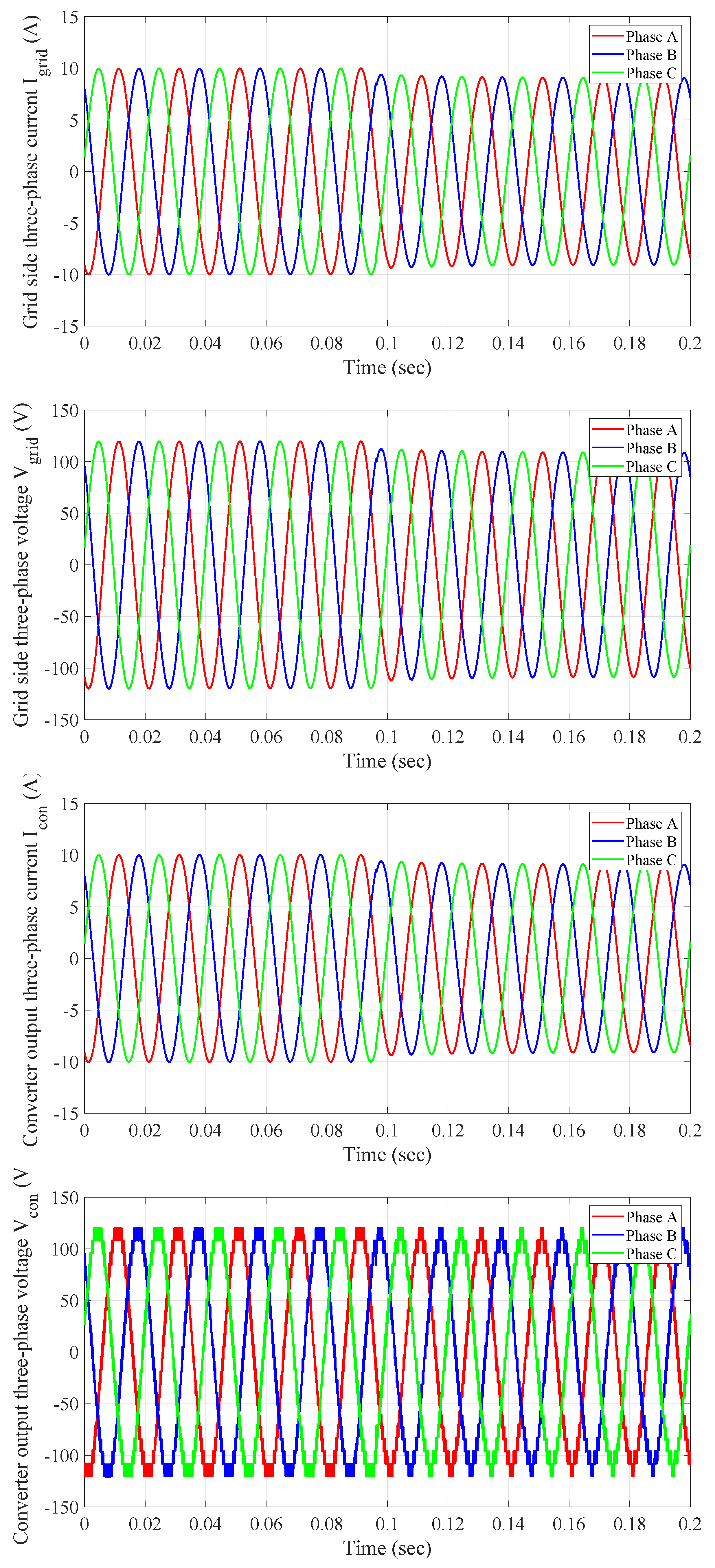
Figure 11.
Voltage and current waveforms of the MMC regulated under steady-state conditions.

Figure 12.
The average capacitor voltages in the upper and lower arm voltage waveforms of the MMC regulated under steady-state conditions.
Figure 12.
The average capacitor voltages in the upper and lower arm voltage waveforms of the MMC regulated under steady-state conditions.

Figure 13.
Tracking error waveform of the output current obtained from the conventional control strategy, FLC, and proposed PC.
Figure 13.
Tracking error waveform of the output current obtained from the conventional control strategy, FLC, and proposed PC.

Figure 14.
Output current waveform obtained by applying the conventional control strategy, FLC, and proposed PC, when reference signal was raised at 0.065s.
Figure 14.
Output current waveform obtained by applying the conventional control strategy, FLC, and proposed PC, when reference signal was raised at 0.065s.

Table 1.
System parameters used in the MMC system.
| Parameters | Symbols | Values |
|---|---|---|
| Rated AC-bus frequency | f | 50 Hz |
| DC-bus voltage | 110 V | |
| DC-bus capacitance | 4 mF | |
| Output inductance | 0.7 mH | |
| Number of sub-module (SM) in each arm | N | 3 |
| Arm inductance | 5 mH | |
| Arm resistance | 0.03 | |
| SM capacitance | 900 µF |
Table 2.
Absolute error index (IAE)index of different control schemes, evaluating the steady-state performance.
Table 2.
Absolute error index (IAE)index of different control schemes, evaluating the steady-state performance.
| Control Method | Variable | |||
|---|---|---|---|---|
| Conventional control | ||||
| FLC in [7] | ||||
| Proposed PC | ||||
Table 3.
IAE index of different control schemes, evaluating the dynamic response performance.
| Control Method | Variable | |||
|---|---|---|---|---|
| Conventional control | ||||
| FLC in [7] | ||||
| Proposed PC | ||||
© 2019 by the authors. Licensee MDPI, Basel, Switzerland. This article is an open access article distributed under the terms and conditions of the Creative Commons Attribution (CC BY) license (http://creativecommons.org/licenses/by/4.0/).
Share and Cite
MDPI and ACS Style
Sang, Y.; Yang, B.; Shu, H.; An, N.; Zeng, F.; Yu, T. Passive Current Control Design for MMC in HVDC Systems through Energy Reshaping. Electronics 2019, 8, 967. https://doi.org/10.3390/electronics8090967
AMA Style
Sang Y, Yang B, Shu H, An N, Zeng F, Yu T. Passive Current Control Design for MMC in HVDC Systems through Energy Reshaping. Electronics. 2019; 8(9):967. https://doi.org/10.3390/electronics8090967
Chicago/Turabian StyleSang, Yiyan, Bo Yang, Hongchun Shu, Na An, Fang Zeng, and Tao Yu. 2019. "Passive Current Control Design for MMC in HVDC Systems through Energy Reshaping" Electronics 8, no. 9: 967. https://doi.org/10.3390/electronics8090967
Note that from the first issue of 2016, this journal uses article numbers instead of page numbers. See further details here.