1. Introduction
Recently, as traffic volumes have become increasingly complex, the need for an advanced driver assistance system (ADAS) has emerged to reduce life-threatening situations caused by traffic accidents. ADAS uses sensors and electronics to help drivers make better decisions [
1]. With the remarkable advances of sensors and electronics in recent years, the expectations for ADAS have significantly increased. In such, various studies have been conducted related to tracking a vehicle using a camera [
2], measurement of the driver’s heart rate using sensors mounted on the seat of the vehicle [
3], notification of the recommended vehicle speed based on weather, road, and vehicle condition [
4], and communication between autonomous vehicles [
5]. With the advancements in ADAS, the underlying software has become more complex; where interoperability, portability, and maintainability became crucial requirements. These requirements are addressed by automotive software platforms such as Open Systems and their Interfaces for the Electronics in Motor Vehicles (OSEK) [
6] and AUTOSAR [
7,
8,
9].
Traditional original equipment manufacturers (OEMs) and electronic control unit (ECU) manufacturers use a variety of hardware and software without a uniform standard to develop the ECU of vehicles. Without a uniform standard, ECUs are developed in a hardware-dependent structure that requires new software to be created when the hardware is changed. In this way, the developed ECU reduces the reusability and reliability of software and increases development costs. To address such problem, German automotive companies jointly started OSEK with the aim to develop “an industry standard for an open-ended architecture for distributed electronic control units in automobiles.” It provides standard interfaces incorporating hardware and software for easier development and reusability. However, the constant increase in system complexity of automobiles leads to the current development of automotive open system architecture (AUTOSAR). AUTOSAR aims to develop the software independent of the hardware and can be distributed or reused in different components of ECUs [
10,
11]. AUTOSAR separates hardware-independent application software from the hardware-oriented software through the runtime environment layer. In this study, we focus on the development of a collision warning system based on AUTOSAR.
Solutions for AUTOSAR development are divided into commercial [
12] and open source distributions [
13]. In a commercial AUTOSAR solution, the vendor provides a well-established development methodology from the development environment to the implementation in accordance with the development tool. Thus, it is relatively easier to use in project development but with higher licensing costs. Conversely, open source solutions can decrease development costs as the licenses are free and can easily be acquired. However, documentation and implementation procedures are not well-defined. For example, Sun et al. [
14] built a software framework based on controller area network (CAN) bus following the AUTOSAR acceptance test. Similarly, Jansson et al. [
15], implemented FlexRay communication using the AUTOSAR communication stack. Both researchers offered performance evaluation of the communication stack and the required implementation mechanisms. However, these studies did not offer actual automotive application. A vehicle seat heating system based on the open source AUTOSAR is presented by Melin et al. [
13] and the application of the message authenticated controller area network (MaCAN) protocol for vehicular applications Kulaty et al. [
16] is proposed. However, all of these studies focus only on the implementation of the communication stack or the specific application. Design and implementation procedures were not considered. For this reason, engineers and practitioners mentioned complexity, learning curve, and bad documentation as the recognizable drawbacks of AUTOSAR [
10].
To address these shortcomings, this paper aims to provide a comprehensive reference for practitioners, especially beginners, on the design and implementation of open source AUTOSAR for automotive applications. To begin, we organized the basic concepts of AUTOSAR to make it easier to understand the architecture and each fundamental component. Although the AUTOSAR manual [
17] describes most of the parts, this study offers a simplified explanation based on the first-hand experience which is very helpful especially in practical implementation. Also, we propose an improvement of the existing development methodology [
18,
19,
20,
21] based on an open source AUTOSAR. This focuses on defining the underlying tools required at each development stage which is very necessary for designing flexible and reusable software modules for a complex system such as an ADAS.
In order to validate the methodology, we developed a collision warning system with actual ultrasonic sensors and light-emitting diodes (LEDs) connected to an AUTOSAR evaluation kit, NXP MPC574XG-324DS [
22], including the complete details and implementation procedures. Visualization of the sensor data was performed in a virtual robot experience platform (V-REP) [
23,
24]. Because an ADAS such as the collision warning system is composed of complex software and electronic hardware devices, precise control period and minimal computational delay should be ensured for proper device handling. Thus, the entire system should display deterministic behavior and responsiveness, i.e. real-time performance. Due to the lack of documentation and established methods in determining the performance of open source AUTSOAR, this study also provides various evaluation methods aiming to measure the real-time performance of the tasks running in the runtime environment of AUTOSAR. These include the task periodicity test to ensure that the system meets real-time constraints and latency tests on each layer of the AUTOSAR communication stack. The results of these evaluation methods can help developers in improving the overall safety of their developed vehicular system. Although we have implemented the proposed procedures and evaluation methods in a collision warning system, these are applicable to any other types of ADAS applications and is very useful as a guideline for integration open source AUTOSAR to more complex vehicular projects.
In summary, the contribution of this study is twofold: First, we provide the complete details on developing a collision warning system using an open source AUTOSAR; including the simplified basic concepts of AUTOSAR and improvement of the existing AUTOSAR development methodology. Second, we propose various evaluation methods measuring the real-time performance of the tasks in the runtime environment and the overall latency of the communication stack. This paper is organized as follows: The second section presents the simplified basic concepts of AUTOSAR. The proposed ADAS development process using an open source AUTOSAR is described in
Section 3. Experiment procedures and results are shown in
Section 4. Evaluation of the implemented system using the proposed evaluation methods are performed in
Section 5 and the last section summarizes the concluding remarks.
2. AUTOSAR Basic Concept
AUTOSAR is a standard software consisting of three major layers: the application software component (ASW), runtime environment (RTE), and basic software (BSW). Each layer is modularized into various software components, connected with each other over a virtual network called the virtual functional bus (VFB) [
25].
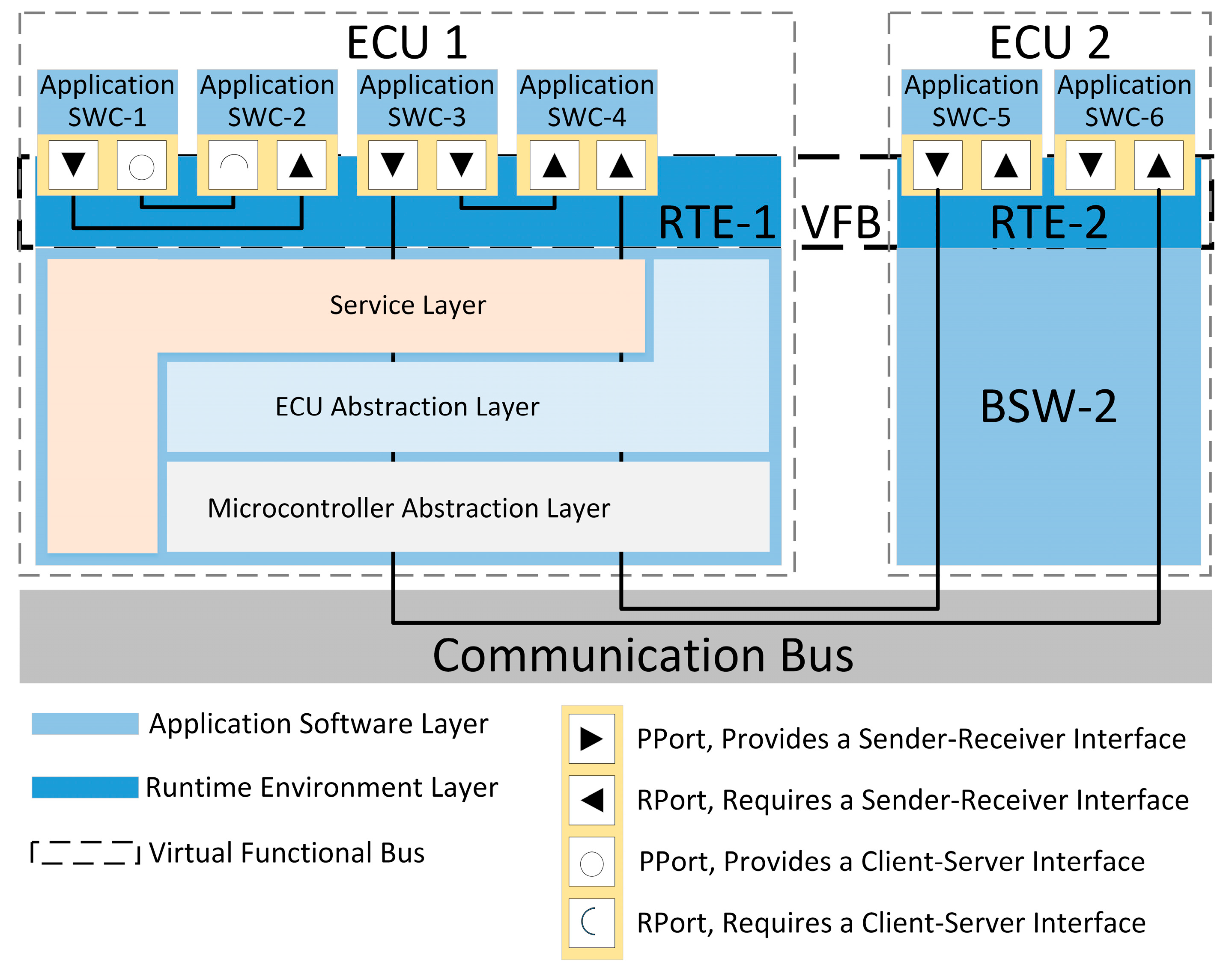
Figure 1 shows the basic software architecture of AUTOSAR [
26].
The ASW layer consists of the AUTOSAR software component (SWC) mapped into a specific ECU. The SWC is separated into minimum units that can be reused based on the function of the AUTOSAR application, in terms of information hiding and encapsulation and is independent of the hardware and network bus. Communication between different SWCs or between an SWC and BSW is performed through a VFB. It defines an interface for an access point that can be input and output data to the SWC, and a communication method to communicate with other SWCs or BSWs. The SWC can send and receive necessary data through the port and the interface regardless of the ECU in which the communication object is located. The communication interface includes a sender-receiver interface and a client-server Interface. In the case of the sender-receiver interface, data is transmitted from the sender to the receiver by the signal passing method. The data type of the transmitted data from the sender must match the data type specified by the receiver. In the case of the client-server interface, the function of the server is called by the client in the function call method. The data type of the parameter to be used when calling the server function in the client should match the data type specified in the server.
The RTE layer serves as a middleware for managing communication between the ASW layer and the BSW layer of the same ECU. The RTE provides the same abstracted interface regardless of whether the communication is within the ECU or through the external communication network, so the SWCs of the ASW layer are independent of those of the BSW layer. The VFB of the RTE layer provides the AUTOSAR communication mechanism for the client-server and sender-receiver interfaces and provides communication service to the SWC. The VFB is a technical concept that enables the development of the functional architecture of the entire system, independent of the actual hardware topology of the ECUs and the network [
25]. In
Figure 1, SWC-1 and SWC-2 communicate within ECU 1, but in the case of SWC-3 to SWC-6, communication is performed between the SWCs of ECU 1 and ECU 2. Since all SWCs are designed to communicate in one VFB, they are designed the same as SWC-1 and SWC-2 when developing SWC-3 to SWC-6, regardless of the position of the mapped ECU. After the SWCs are mapped to the ECU, the VFB is implemented as RTE-1 and RTE-2 in each ECU as shown in
Figure 1. As a result, RTE-1 and RTE-2 play an individual role in VFB.
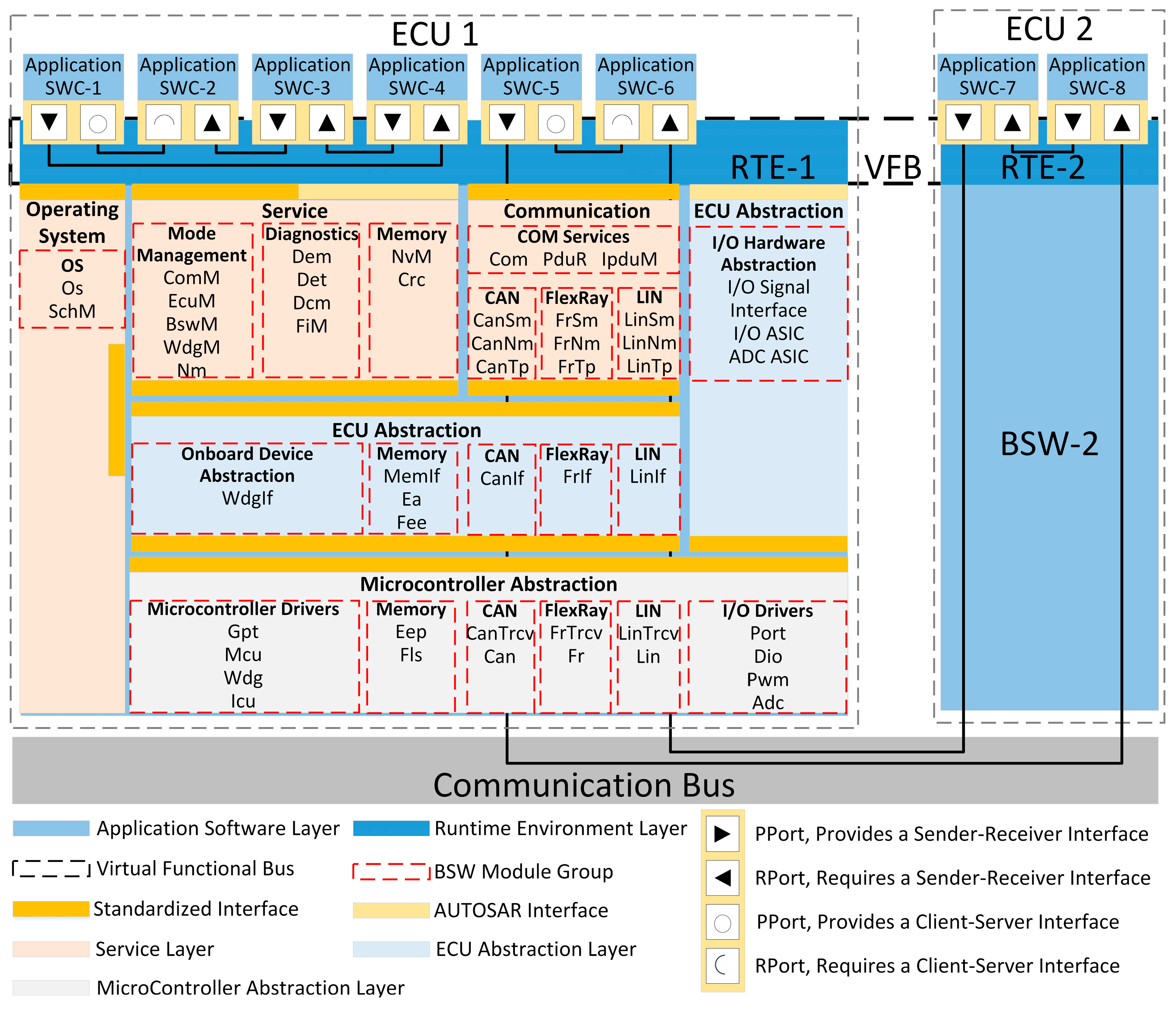
Figure 2 shows the detailed software architecture of AUTOSAR, which was unified based on our own first-hand experience and interpretation of the AUTOSAR manual [
26]. BSW, which was simply presented in
Figure 1, is detailed in
Figure 2.
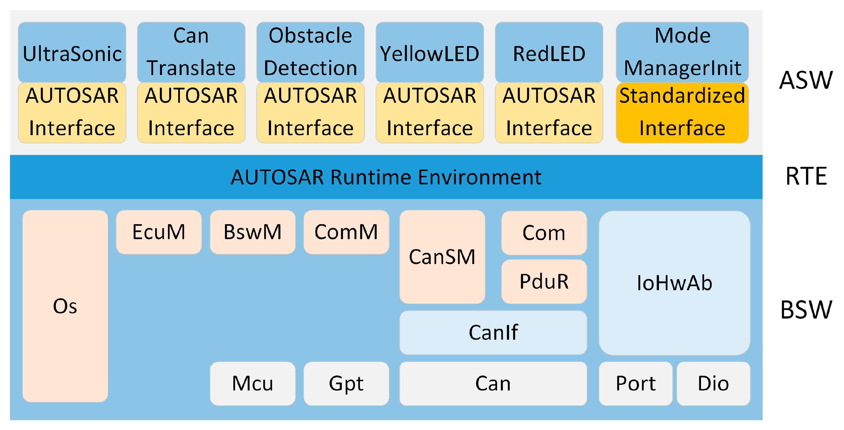
The BSW is also a standard software layer that provides the services required for the ASW layer and the SWCs to perform specified tasks. The BSW consists of a service layer, an ECU abstraction layer, and a microcontroller abstraction layer (MCAL). The service layer is divided into system services, memory services, and communication services depending on the functions to be provided. System services are a group of modules and functions that can be used in all layers of the module. System services provide a real-time operating system, vehicle network communication and management, the ECU status management function, WatchDog, and the diagnostic service function. In
Figure 2, the OS module group, mode management module group, and diagnostics module group correspond to system services. Memory services consist of a group of modules responsible for nonvolatile data management. The standard AUTOSAR interface provides nonvolatile data to the ASW layer; memory location and attribute abstraction; a nonvolatile data management mechanism for storage, load, checksum protection, and verification; and stable storage. In
Figure 2, the memory module group is provided by the memory service.
Communication services are a group of modules that perform functions such as CAN, local interconnect network (LIN), and FlexRay to provide communication to higher layers through a unified interface. Communication services provide a service for communication network management and a unified interface that eliminates the dependency of the lower layers. Additionally, it accesses the communication driver through the abstracted communication driver and has a structure that is independent of the communication driver of the MCAL layer. Communication services provide a unified interface that eliminates the dependency of the lower layers on diverse applications and vehicle network diagnostic communications, allowing applications to be developed without consideration of protocol and message attributes. Internally, there is a network manager (NM), state manager (SM), and transport protocol (TP) for communication networks, such as CAN, LIN, and FlexRay. Furthermore, modules such as communication (Com) and protocol data unit router (PduR) exist. In
Figure 2, the service module groups CAN state manager (CanSm), CAN network manager (CanNm), CAN transport protocol (CanTp), FlexRay state manager (FrSm), FlexRay network manager (FrNm), FlexRay transport protocol (FrTp), LIN state manager (LinSm), and LIN transport protocol (LinTp) are provided in the communication services [
27,
28].
The ECU abstraction layer serves as an interface and driver for creating an upper layer of software, independent of hardware so that MCAL can be used. The ECU abstraction layer is independent of the microcontroller, but it is dependent on the ECU board used. The ECU abstraction layer is divided into onboard device abstraction, memory hardware abstraction, communication hardware abstraction, and input/output (I/O) hardware abstraction depending on the functions to be provided. Onboard device abstraction contains drivers for the ECU onboard devices not visible as sensors or actuators, such as internal or external watchdogs. The function of this module group is to abstract from ECU specific onboard devices. In
Figure 2, the watchdog interface (WdgIf) module is included in the onboard device abstract. Memory hardware abstraction is a group of modules that abstracts internal or external memory devices. It provides a mechanism for accessing internal or external memory devices, allowing access through the same interface regardless of the type of memory, such as electrically erasable programmable read-only memory (EEPROM) or Flash. In
Figure 2, the memory abstraction interface (MemIf), electrically erasable programmable read-only memory abstraction (Ea), and flash electrically erasable programmable read-only memory emulation (Fee) modules are included in the onboard device abstraction. Communication hardware abstraction is a group of modules that abstract communication hardware. To use a specific communication protocol, you must implement the communication hardware abstraction module for that protocol. In
Figure 2, the CanIf, FrIf, and LinIf modules are included in the communication hardware abstraction. I/O hardware abstraction is a group of modules that abstract the I/O hardware. The main purpose of I/O hardware abstraction is to provide I/O access to the ASW layer and the SWCs. It can be accessed from the upper layer through the I/O signal interface without going through the service layer. In
Figure 2, the Port, Dio for digital input/output (DIO), Pwm for pulse width modulation (PWM), and Adc for analog to digital converter (ADC) modules are included in the I/O hardware abstraction.
The microcontroller abstraction layer (MCAL) is the lowest software layer of a BSW. In order to avoid direct access to the microcontroller register in the high layer software, access to the hardware is done through the MCAL device driver, which includes hardware-dependent drivers such as ADC, PWM, DIO, EEPROM, and Flash. Access to the microcontroller’s registers is routed through MCAL, which makes the upper software layer independent of the microcontroller. Depending on the function, the microcontroller driver, memory driver, communication driver, and I/O driver are categorized. This provides an application programming interface (API) for devices and their connection to the microcontroller.
3. Collision Warning ADAS based on an Open Source AUTOSAR
In this section, we describe the design and implementation procedures of a simple collision warning system comprised of ultrasonic sensors and LEDs, with the aim to provide an in-depth reference for an open source AUTOSAR. We present the improved design methodology of developing AUTOSAR applications, which focuses on defining the underlying tools required at each development stage. We also describe the complete design and implementation procedures of a collision warning system including the step-by-step process from configuring both the SWC and BSW. This includes RTE and SWC runnable implementations for developing ADAS applications.
3.1. Design Methodology
The existing AUTOSAR development methodology [
18,
19,
20,
21] has difficulty in clarifying the development process because determining the underlying tools at each development stage is not clearly defined. For commercial AUTOSAR, it is not a problem because the vendor providing the solution provides detailed manuals, but because the open source AUTOSAR does not have a clear methodology for development, there are many challenges for the developers. In this paper, a specialized procedure is proposed for development using open source AUTOSAR. The existing AUTOSAR development process has been reconfigured in five stages. The proposed procedure using ARCCORE’s open source AUTOSAR development solution is shown in
Figure 3.
Step 1: This step is performed in the SWCD Editor of Arctic Studio. The SWC description and system description should be defined for the applications in each software component of .arxml files. We classify the SWCs according to the function of the AUTOSAR software to be implemented and define the communication interface, port, and data type in each SWC. After defining the SWCs, the defined SWCs are used to create prototypes that are objects of the SWC. Then, the communication ports of the prototypes are connected for communication and the signals to the external ports for outside the ECU are mapped.
Step 2: This step is performed in the BSW Editor of Arctic Studio. The BSW module for providing the service required by the SWC is defined and configured in an export.arxml. Modules that should be configured by default at this stage are OS modules for task scheduling, EcuM modules for ECU management and BswM modules for BSW management. Other modules are added to perform their functions according to the functions required by the AUTOSAR SWC. If GPIO is to be used, add the I/O modules. To implement communication between other ECU, add the communication modules. You can configure the detailed features of each module for all added modules. For OS modules, task creation, Priority and Period can be configured. The addition and configuration of modules performed at this stage are all made in the GUI environment. Finally, the ECU extract method is conducted to create an extract.arxml file.
Step 3: This step is the RTE configuration step performed in the RTE Editor and BSW Editor of Arctic Studio. RTE configuration is based on the extract.arxml files created in Step 1 and 2. As a result of this step, source code and header file for the RTE and BSW are generated. The RTE configuration process instantiates the SWC prototype created in Step 1 and maps the tasks and events created in the OS module configuration of Step 2 to the runnable of the instantiated SWC. Through this process, the runnable of the SWC is scheduled and executed in the AUTOSAR OS. After the RTE configuration is completed, RTE and RTE contract files are generated to connect the BSW and the ASW using the generate function provided by the RTE editor. In the RTE contract file, an API for calling the service provided by the BSW layer in the application of the ASW layer is defined. Finally, generate the BSW code using the generate function provided by BSW editor.
Step 4: The runnable, which is a function that defines the SWC, is created in C language. The runnable refers to the RTE contract file which defines the API for communication through the RTE which is generated as a result of the execution of Step 3.
Step 5: The source code and header files generated as a result of Steps 3 and 4 are built and used to generate executable files that will run on the ECU. The tool chain and environment variables of the MCU are specified and used in the ECU. These are performed in Arctic Studio.
3.2. Designing a Collision Warning System
A collision warning system is a system that allows the driver to recognize and avoid an obstacle by generating a warning to the driver according to the distance between the obstacle and vehicle when the obstacle exists in a blind spot that the driver cannot recognize. In this paper, the distance from an ultrasonic sensor to the obstacle is measured and transmitted to the ECU. The ECU determines the warning level according to the distance data. As a demonstration system, V-REP is used to show the visualization of sensor data, which is transferred through the CAN bus. The control signal is also displayed with an LED indicator. The following sections provide a detailed design procedure of a collision warning system described in the previous section.
3.2.1. SWC Configuration
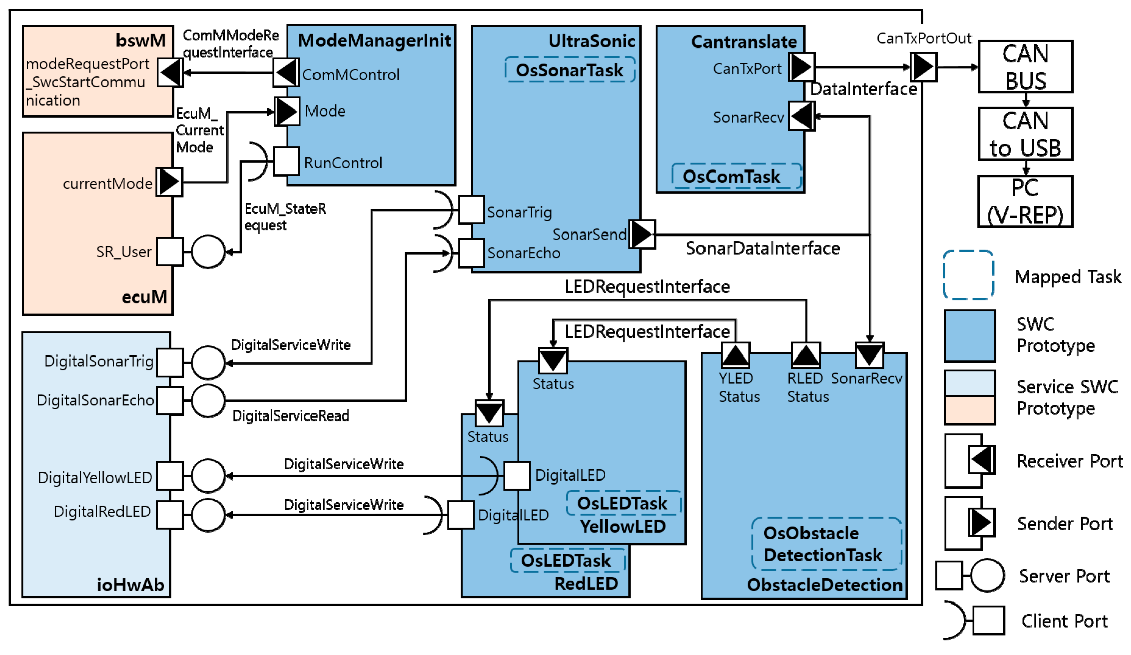
The Communication interface at SWC is classified into standardized interface and AUTOSAR interface according to the communication target module as shown in
Figure 4. The standardized interface is used with the BSW, and the AUTOSAR Interface is used with the SWC. Standardized interface is provided by the AUTOSAR framework and does not need to be defined. AUTOSAR Interface design is classified according to the size and type of data. Three interfaces are defined in this paper: The sonar data interface (SonarDataInterface) is used to transmit the measured ultrasonic sensor data, the data interface (DataInterface) is used for CAN data transmission, and the LED request interface (LedRequestInterface) is used for LED control request. When communicating using the SonarDataInterface and DataInterface, data represented distances and four bytes of an unsigned int data type are used. When communicating using LedRequestInterface, the data only needed to indicate whether to turn on/off the LED for control, so a one byte Boolean data type is used. In
Figure 4, those are used to connect the communication ports of SWC Prototypes.
The SWCs that constitute the communication port and internal behavior are designed by classifying the operations performed in the ECU into five functions: the distance measurements to the obstacle, data transmission with the CAN bus, warning level judgment, LED control for the warning, and ECU initialization. Additionally, the runnable (executable file) is configured for each SWC. Designed SWCs provide a structure for instantiating SWC prototypes. The application layer with the detailed operation and connection of each SWC prototype is shown in
Figure 4. In the developed collision warning system, the SWCs are divided as the UltraSonic, CanTranslate, ObstacleDetection, LEDActuator, and. The UltraSonic converts the measured data from the ultrasonic sensor into distance data in meters. The calculated distance data is then transmitted to the CanTranslate and ObstacleDetection for further processing. After receiving the distance data, the CanTranslate relays them to the CAN bus through the CAN communication stack. On the other hand, the ObstacleDetection determines the color of the LED to be controlled according to the same distance data received from the UltraSonic and signals the LEDActuator. The LEDActuator performs the actual control of the connected LEDs, whether YellowLED or RedLED. The ModeManagerInit transmits the ECU control signals to the ecuM and bswM, and lets the BSW perform Ecu, Gpt (general purpose timer), and communication initialization functions. Through these operations .swcd and .sysd files are finally created for SWC description and an .arxml file is also generated through ECU Export.
3.2.2. BSW Configuration
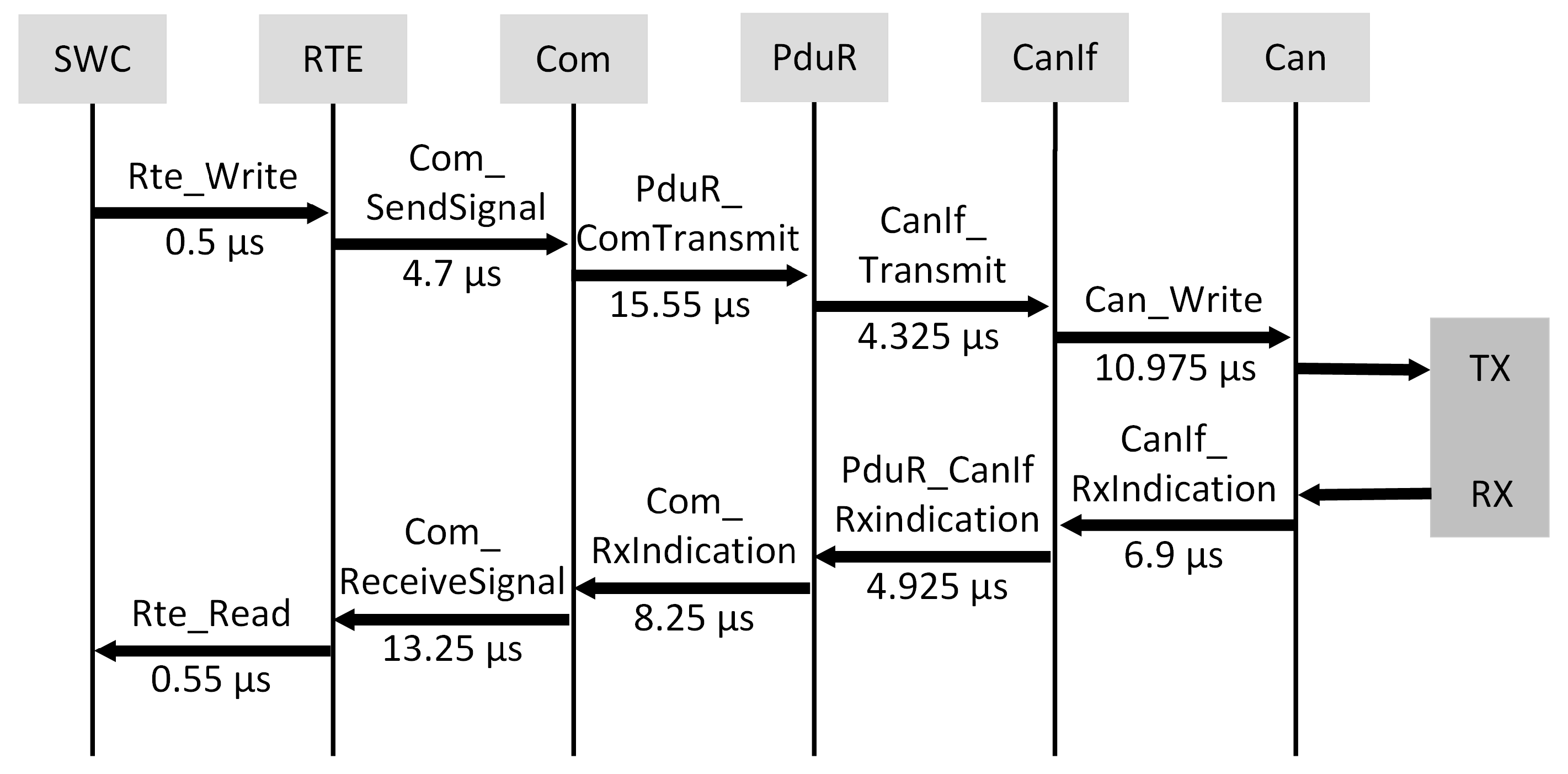
In order to provide the services that the SWC needs to perform specific functions, the modules utilized in the BSW are defined and configured. In such, the UltraSonic SWC requires timer services for measuring the return time of the Digital I/O and ultrasonic waves. CanTranslate needs the CAN communication services. As the ObstacleDetection SWC does not request any hardware resources, a BSW service is not necessary. On the other hand, hardware-related SWCs such as the YellowLED and RedLED require the Digital I/O service. The service required by ModeManagerInit is an ECU management function to perform the initialization of the ECU, timers, and communication. In addition, OS service is required for task creation and scheduling. The Com, PduR, CanIf, and Can modules are used to implement the CAN communication stack [
14,
28]. The CanSM module is used to implement the control flow of the CAN BUS. The Dio, Port, and IoHwAb modules for Digital I/O control are used; the Gpt module for timer control is used; the EcuM, BswM, Mcu, and EcuC modules are used for system management; and the Os module is used to manage the creation and scheduling of AUTOSAR tasks.
Figure 5 shows the layered structure of the collision warning system after performing SWC and BSW configurations.
3.2.3. BSW and RTE Generation
The next procedure is to generate the RTE and BSW codes. RTE is configured by the .arxml file from the SWC and BSW configuration mentioned in the previous subsections. The RTE configuration process instantiates the SWC prototype configured during the SWC configuration process, such that the RTE can recognize the SWC as part of the ASW layer. After instantiating the SWC prototype, the runnable is mapped to the Task and Event configured in the Os module in the BSW configuration. Through this process, the SWC runnable is mapped to a task managed by the OS scheduler and is scheduled in a task unit.
The tasks mapped to SWCs in the collision warning system are displayed as a dotted line in
Figure 4. Those are OsObstacleDetectionTask, OsLEDTask, and OsSonarTask, OsComTask. The OsStartupTask initializes the BSW module by calling EcuM_StartupTwo as the first task to be executed. This task is not mapped and runs only once when the OS is executed. OsBswServiceTask, which is also not mapped, calls the MainFunction of the ComM, Com, EcuM, CanSM, Can, and BswM modules, which are BSW modules that should be called periodically to provide services. This task is also not mapped and is scheduled by the BSW Scheduler to run in polling method every 10 ms. The OsObstacleDetectionTask is triggered every 20 ms and the runnable in the ObstacleDetection SWC Prototype is mapped. The OsLEDTask is triggered every 10 ms and the runnables in the YellowLED and RedLED SWC Prototypes are mapped. The OsSonarTask is triggered every 40 ms and the runnable in the Ultrasonic SWC Prototype are mapped. The OsComTask is triggered at data is received at SonarRecv port, and the runnable in the CanTranslate SWC Prototype are mapped.
3.2.4. SWC Runnable Implementation
The algorithm of the SWCs are designed in the SWC configuration process; a .c file is implemented for each SWC and the runnable is implemented as a function inside the .c file. This implemented the communication between an SWC and other SWCs or communication between the SWC and BSW, by referring to the API defined in the RTE contract file generated as a result of RTE generation.
4. Experiment Results
Experiments were conducted to verify the operation of the developed collision warning system based on the proposed methodology in the previous section. The collision warning system operates by acquiring the distance from ultrasonic sensors, and depending on the measured distance of the obstacle, the state of the corresponding LED changes. In this section, we specify the hardware and software environment of the experimental testbed, verified the operation of the developed system on top of a mobile platform, and visualized the sensor data using the visualization software, V-REP.
4.1. Hardware Environment
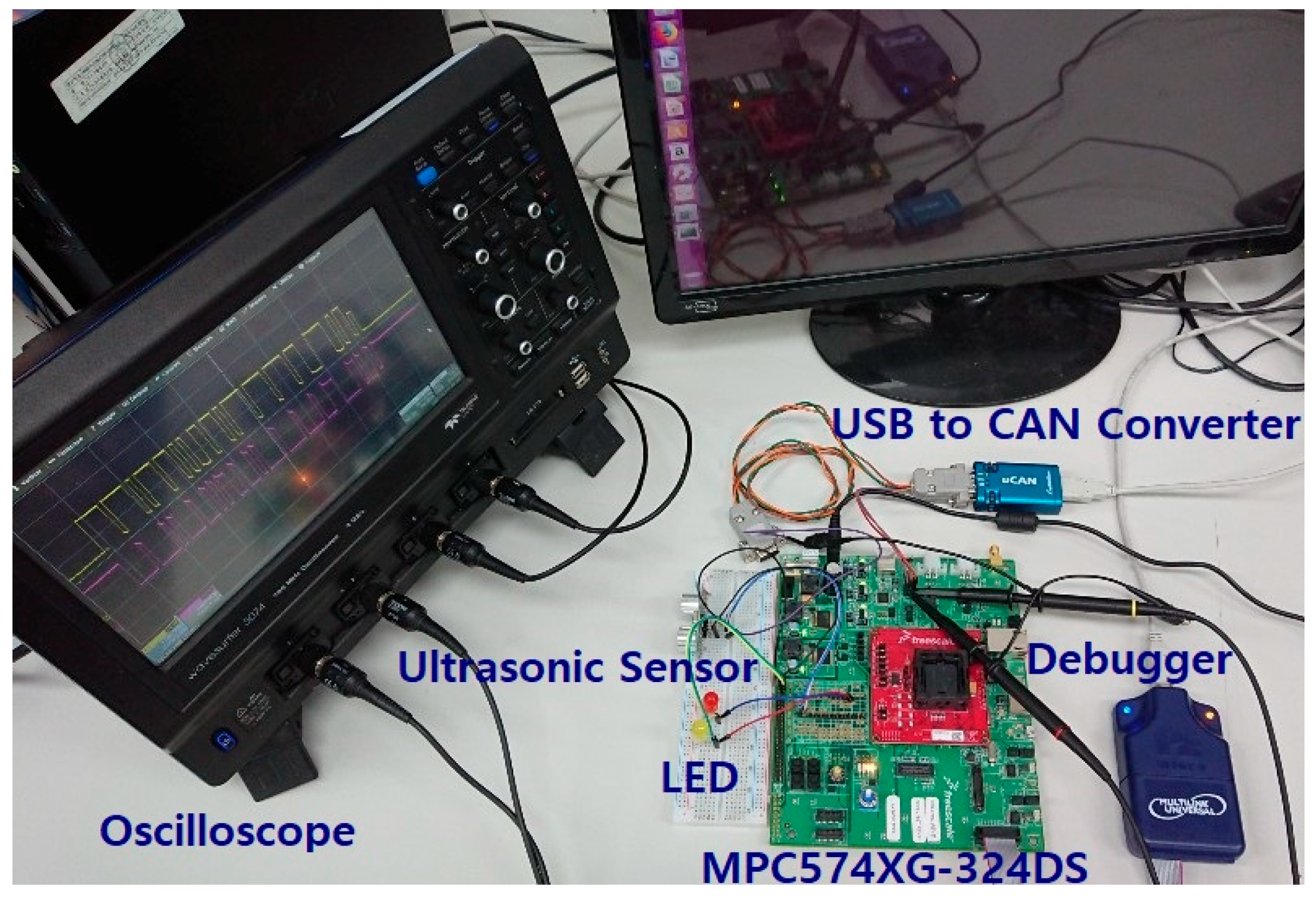
In our developed system, we used the MPC574XG-324DS board with MPC5748G MCU as the ECU. The USB Multilink Universal debug probe is used for debugging and software upload. The USB to CAN converter is used for communication between a PC and the ECU through CAN protocol. The data transferred to the PC are visualized using the tool, V-REP [
23,
24]. Ultrasonic sensors are used to measure the distances from obstacles in the collision warning system. Red and yellow LEDs inform the user about the risk of the obstacles. An oscilloscope is used to identify the CAN message frames. The complete hardware environment is shown in
Figure 6.
4.2. Software Environment
In this study, the open-source AUTOSAR design is based on the Arctic Core 21.0.0 from ARCCORE along with the integrated development environment (IDE), Arctic Studio 21.0.0, running under Eclipse. To develop AUTOSAR software for the MPC5748G MCU, a toolchain of the PowerPC architecture supported by the IDE is required. Currently, supported toolchains are CodeWarrior, Diab, and Greenhills. However, CodeWarrior (the toolchain for NXP boards) does not support the MPC57xx series of MCUs. Therefore, we used the toolchain provided by the “S32 Design Studio for Power Architecture” IDE provided by NXP for the PowerPC architecture.
After installing the toolchain, the environment variables to build the AUTOSAR project is configured in Arctic Studio. These include BOARDDIR, COMPILER, and CROSS_COMPILE. BOARDDIR, for example. COMPILER is set to “gcc” to enable the usage of the gcc cross compiler and CROSS_COMPILE defines the directory where the toolchain is installed. In order to generate the code for the BSW that can be operated on the target board, the MCAL item, found in the ECU information and options of the BSW Editor of Arctic Studio, were set to MPC5748G, the MCU of the target board. Finally, a robot simulator, V-REP PRO EDU, is installed to visualize the behavior of the ECU on the PC.
4.3. Collision Warning System Operation Test
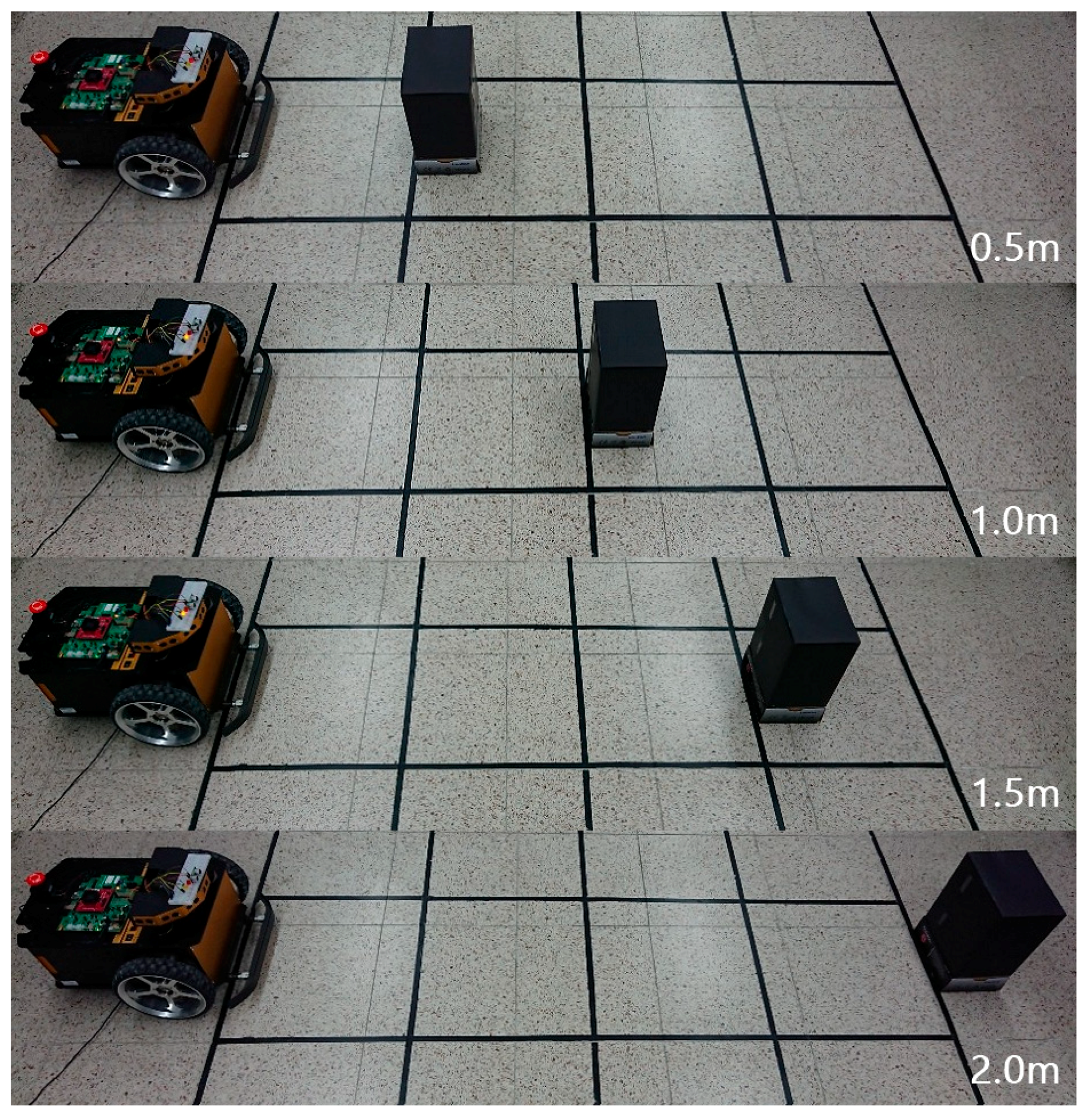
In order to verify the operation of the collision warning system in a real environment, the change of the LED was observed while moving the distance of an obstacle from 0.5 to 2.0 m. The red LED turns on when the distance from the obstacle is less than 1.0 m, the yellow LED lights up when it is between 1.0 m and less than 2.0 m, and both LEDs remain off if the obstacle is more than 2.0 m away. The test results are shown in
Figure 7, showing the distance of the obstacle from the collision warning system in 0.5 m increments. The size of one block of the tile is 0.5 m in width and 0.5 m in height. Through these results, we have verified the normal operation of the collision warning system.
4.4. Sensor Data Visualization Using V-REP
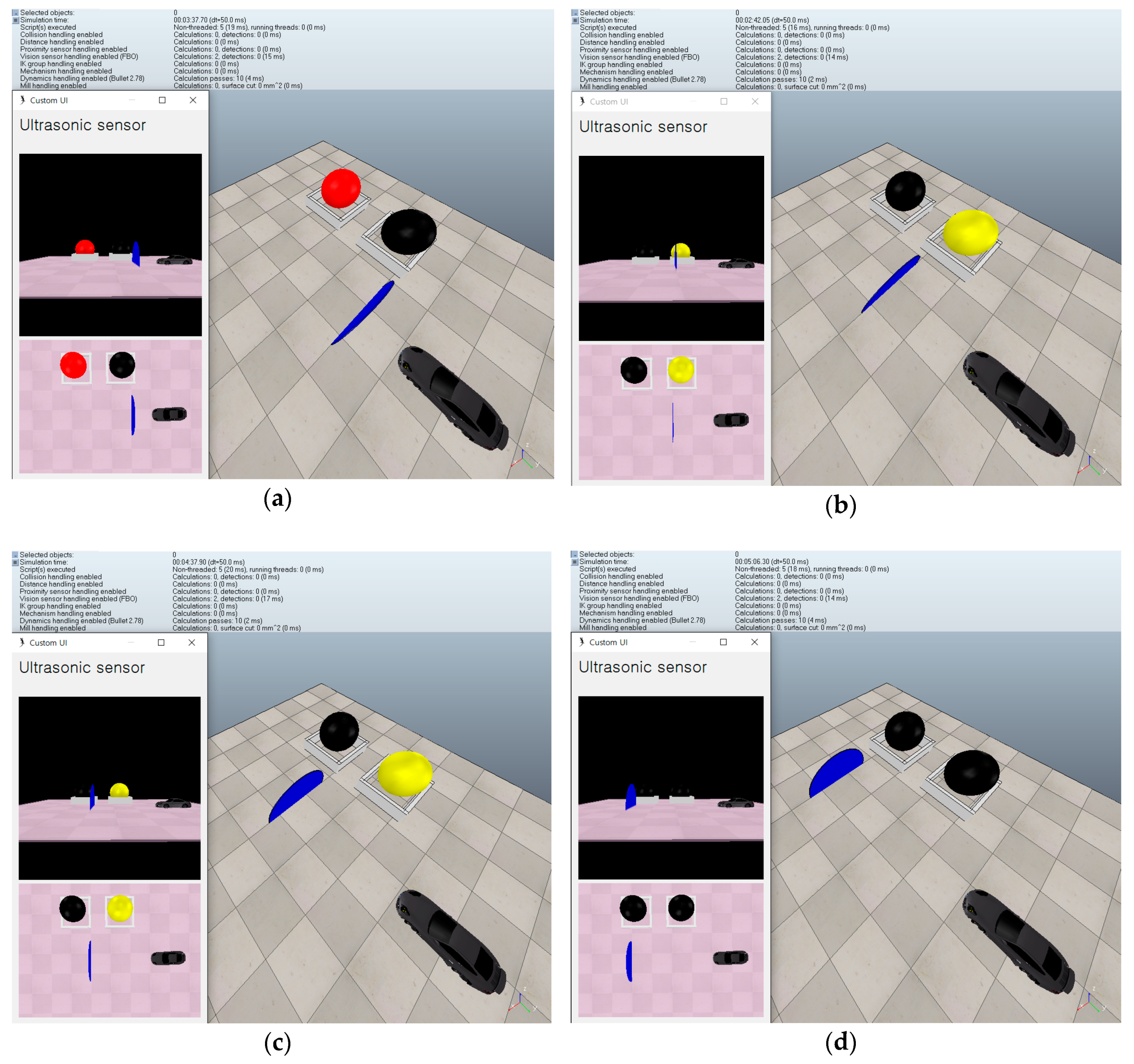
In this section, V-REP visualization is performed to visually confirm the operation of the collision warning system and the data of the ultrasonic sensor as described in the previous subsection.
Figure 8 shows the result of the visualization of ultrasonic sensor data sent from ECU to CAN bus using V-REP of host PC using USB to CAN Converter. To maintain consistency with the actual experiment environment, the size of one block of tile was set to 0.5 m for both width and height. The ultrasonic sensor was attached to the front part of the vehicle, and the position of the obstacle is indicated by a blue disk. The LEDs to indicate the risk of the obstacles were composed of the same red and yellow as the actual hardware configuration. The UI on the left shows the data of the ultrasonic sensor, and the view from the side, and the view from above. We confirmed that the movement of the blue disc and the state of the LED change according to the distance between the ECU and the obstacle. The results show the same behavior with the actual experiment in the previous section.
6. Conclusions
In this paper, a procedure was presented to develop an ADAS using open source AUTOSAR. It was addressed using open source AUTOSAR to ensure the interoperability, portability, and maintenance of complex ADAS software. To develop a system using AUTOSAR, a development solution must first be selected. The development procedure of commercial solutions is well-defined and easy to develop but it is difficult to acquire a license. Licenses can be easily acquired for an open source solution, but there is no established procedure for development, making it difficult for users to develop. Therefore, the detailed design procedure for ADAS based on open source AUTOSAR needs to be defined for most engineers.
Here, we have presented a development procedure that includes design, implementation, and evaluation using open source solutions. To verify the proposed procedure, we implemented a simple collision warning system for ADAS using ARCCORE’s open source AUTOSAR solution Arctic tool and an MPC574XG-324DS board equipped with NXP’s MPC5748G MCU. Real-time performance evaluation, visualization of the sensor data, and communication stack evaluation were performed to test the implemented systems. We confirmed that the implemented system satisfied the real-time constraints and verified the sensor data through visualization. This paper will be a promising result for engineers who want to develop a more complicated ADAS using open source AUTOSAR, from the development environment to implementation and evaluation.
We have provided the entire AUTOSAR and V-REP software for the collision warning system in this paper available at [
34] enumerating the BSW modules and their usage.


