Automated Network Topology Extraction Based on Graph Theory for Distributed Microgrid Protection in Dynamic Power Systems


1
Fukushima Renewable Energy Institute, AIST (FREA), Koriyama 963-0298, Japan
2
The College of Engineering & Science, Victoria University, Werribee, VIC 4P62+53, Australia
*
Author to whom correspondence should be addressed.
Electronics 2019, 8(6), 655; https://doi.org/10.3390/electronics8060655
Submission received: 10 May 2019
/
Revised: 31 May 2019
/
Accepted: 3 June 2019
/
Published: 10 June 2019
(This article belongs to the Special Issue Photovoltaic Systems for Sustainable Energy)
Abstract
:Unlike conventional grids, microgrids may utilize different connections and the overall topology can be variable. Considering this, it is required to develop a new protection concept/scheme for safe operation. Maintaining proper selective operation of the relays in these dynamic microgrid structures is a challenge itself. This requires monitoring the connections and updating time delays of the relays which will ensure the desired hierarchy in the system. In this paper, a novel approach has been taken where electrical networks are modeled according to graph theory. Smart algorithms, such as network graph discovery, local manager selection, and protection coordination strategy, are run to automatically detect topology changes and ensure proper protection operation. Furthermore, distributed nature of this method mitigates the risks associated with central controller-based schemes. The developed method is applicable to all power system operations, and it poses a unique implementation in postdisaster recovery. After a disaster or terror attack, this self-diagnosis, self-healing system can identify healthy sections and run them as a standalone system until the relief arrives. The ability of the protection system to be run as a distributed control makes sure that any healthy part of the system can be restructured and utilized, without the dependency, on any central controller or connection.
1. Introduction
Increasing the share of dynamic components, such as distributed generators (dgs), electric vehicles (evs), and storage devices, in power systems changes the conventional operation rules [1,2,3]. Distinct levels of generation, transmission and distribution become intertwined with bidirection power flows. Furthermore, transmission and distribution networks, which are traditionally passive, start contributing to faults. The volume of this contribution depends on the capacity and type of DGs. The fault current levels and their directions are altered in an unconventional fashion [4,5]. For this reason, traditional power system operation principles need to be updated to accommodate these changes. This includes energy management systems as well as protection systems such as wide-area protection schemes [6].
The above is true for all dynamic power systems. Microgrids, which are smaller power systems that can operate on its own or can be connected to the utility, have dynamic structures. Different equipment, such as EVs, DGs, and storage devices, can connect and disconnect at any time. Furthermore, other devices, such as circuit breakers (CBs), can change the topology or operating mode of a microgrid, e.g., from islanded to grid-connected mode. Traditional protection schemes rely on knowledge of the power system network and its components beforehand [7]. While this makes the protection design very convenient, it is very limiting and falls short of meeting safety requirements of dynamic power systems [8]. Some of the prominent protection issues are short circuit power, fault current level and direction, device discrimination, reduction in reach of overcurrent relays, nuisance tripping, protection blinding, etc. [9].
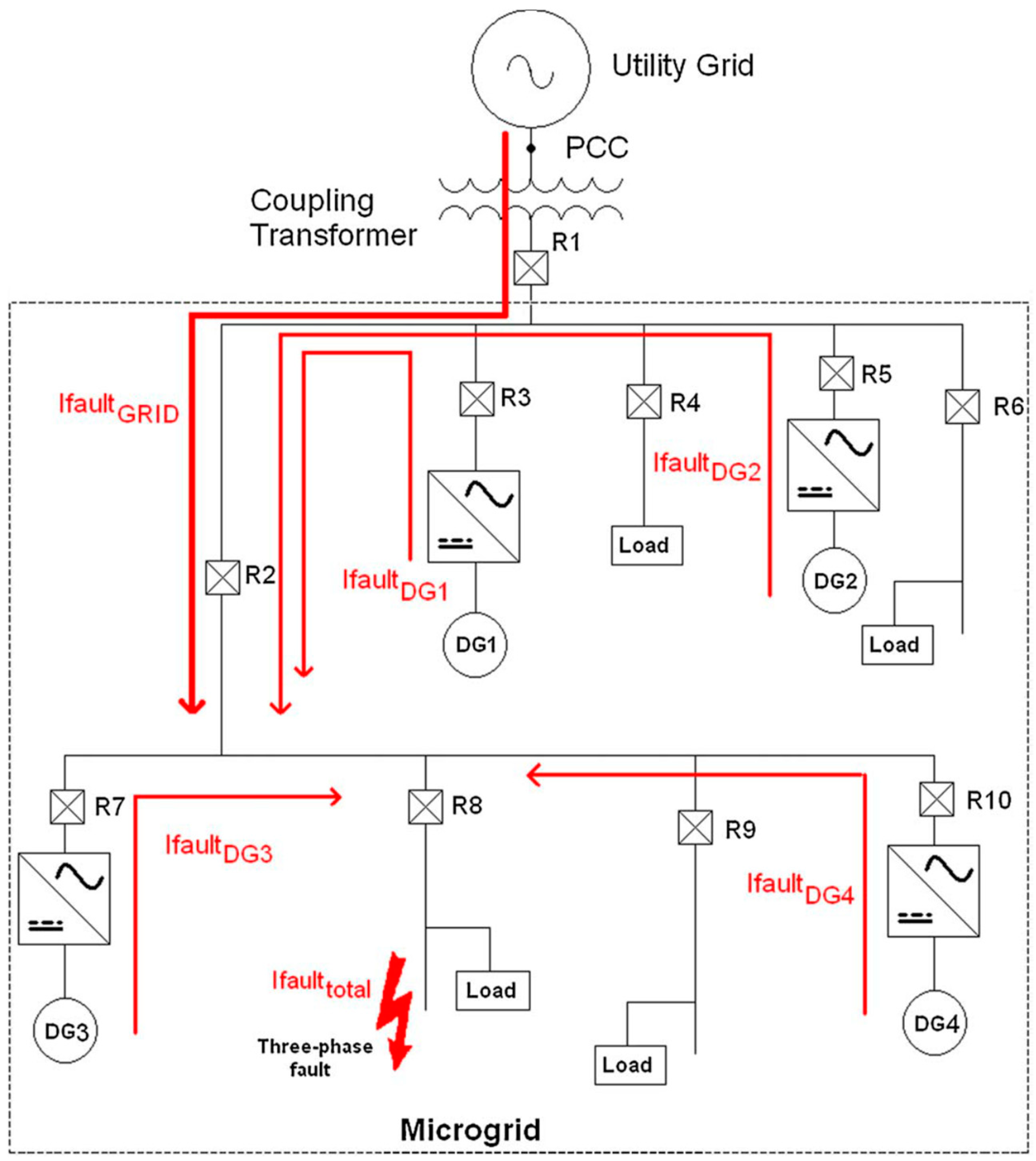
As shown in Figure 1, DGs located in a microgrid contribute to the fault current. Therefore, it is important to know the presence and location of DGs in a network [10]. Furthermore, the grid connection and its contribution play a very big role. As shown, due to relevant locations of fault and DGs, the fault contribution may reach a high level over relay2 (R2) and cause it to trip, although the fault is located somewhere else [11]. DGs may turn on or off anytime, or cease generation due to lack of resource, e.g., cloud coverage for a PV system. This means its fault contribution is not fixed and the protection system should adapt itself accordingly [12]. Moreover, countries have ambitious plans towards increasing their renewable energy shares. This means that more renewable energy based DGs are deployed at power system on a continuous manner. Therefore, new deployments should be easily incorporated into the implemented protection system.
The approach to tackle these novel protection challenges is to establish some sort of coordination between generation and storage devices with protection equipment [13,14]. Such systems are integrated with different components of the network to monitor their operating conditions, updating protection settings, and modes [15]. The common point in all novel protection scenarios is the establishment of a communication link between the components. Majority of these systems also include a central controller to fulfill coordination and adjustment tasks. There are two drawbacks of such systems. First, such schemes require knowledge of the power network beforehand and any slight change in that topology renders them obsolete. Second, presence of central controller creates a bottleneck in the system. If the central controller or its communication link becomes nonoperational, the whole system fails [16].
Microgrids have dynamic structures which constitute a major protection challenge since the conventional selectivity methods assume a fixed network structure and a predetermined relay hierarchy [17]. For desired operation, changing power network conditions should be monitored and reflected on the operation order, i.e., selective levels of relays [18]. This requires extracting the hierarchy of relays under most recent conditions and computing time delays [19]. These can be sent to the individual equipment via communication lines [20]. This requires an algorithm which will determine the current structure of the system and yield the relay hierarchy at all branches of the network.
The use of graph theory for tackling changing behavior of microgrids for different purposes is an emerging field. There are works in the literature focusing on graph partitioning for power flow [21], loss allocation framework [22], as well as distributed secondary control in islanded microgrids [23]. There are studies focusing on implementation of these concepts in power system protection as well. Works in [24,25] represent microgrids as graphs and run Dijkstra’s shortest path algorithm for automated structure detection. However, they require a central controller for implementation. This has disadvantages, considering the dependency on a single controller and possible communication failures. In this respect, a novel distributed microgrid protection approach has been developed in this paper. It models the microgrid according to graph theory, implements smart algorithms to extract the relay hierarchy, and appoints local managers. If the current local manager becomes unavailable due to a malfunction or disaster, a new local manager is appointed, and the operation continues. This approach does not necessitate a priori knowledge of power system configuration and the presence of a central controller. These features make adoption of new deployments much more trivial and pave the way for plug-and-play in power systems.
The developed approach can be utilized in all microgrids during all operating conditions. Moreover, having distributed control with self-diagnosis gives unique self-healing capabilities, which can be utilized for operation of microgrids under emergency conditions. A recent study has shown that natural disasters have quadrupled in the last decade [26], and self-healing systems are the solution for continuous postdisaster power supply [27,28]. Due to unpredictable behavior of such events, adaptive and generic responses are required [29]. Unlike previous approaches, the developed method has the ability to take any microgrid, detect its healthy parts and operate protection system by appointing a local manager. Should an event occur, such as malfunctioning in the local manager, method can be re-run and operation continues.
Specific contributions of the current manuscript are as follows: Energy systems are modeled with Graph Theory for automated control and management. Dijkstra’s shortest path algorithm is implemented to extract the grid structure, i.e., the topology of the power network. In this fashion, the requirement to know the topology a priori is removed for automation systems such as wide-area protection systems and distributed energy resource management systems (DERMS). This paves the way to plug-and-play (PnP) in energy networks. Furthermore, the ability to detect current structure at any given time enables power systems to operate in self-diagnosis, self-healing mode. Therefore, energy systems can operate in topologies not envisioned beforehand, they are automatically detected, optimized, and dispatched.
The organization of this paper is as follows. Section 2 summarizes the background pertaining to protection challenges in microgrids. Section 3 details the fundamentals of network modeling based on graph theory. Section 4 presents the problem in centralized management of network hierarchy data and then proposes a set of distributed algorithms to solve it. Section 5 shows distributed control with an elected local manager for the self-healing ability of smartgrid. Section 6 showcases how distributed control is beneficial in emergency cases where communication lines and/or the electrical grid may be damaged. Finally, Section 7 draws the conclusions.
2. Protection Challenges in Dynamic Networks
Traditional protection systems assume a fixed power system structure and configure relays to operate in a predetermined order. This is done to isolate a fault, or a malfunctioning section, with a circuit breaker that is as close as possible. In this fashion, the remaining part of the network can continue operation without any interruptions. It is perfectly possible that the most downstream circuit breaker, i.e., the one that is closest to actual fault location, may not be able to interrupt the fault current and open the circuit connection. In this case, the next closest circuit breaker above is expected to take charge. These are, normally, larger in fault interruption capacity and can act a backup protection. However, their operation is not the first preference as they isolate a larger portion of the network and affects more customers. Therefore, protection engineers configure circuit breakers, or the relays commanding them, to operate in a selective way, hence, the term selectivity.
In conventional radial power networks, assigning selective levels is trivial since there is only one source of fault current—the feeder—and the natural order is from edges towards the feeder connection. Following this definition, a downstream relay is bound to react faster than any other relay located its upstream. An upstream relay acts as a backup protection, i.e., it waits for its downstream relay to isolate the fault for a predetermined period and only operates if the fault is not cleared before then. Since the structure of the network is fixed, the order of the relays or their relative position to other downstream and upstream relays does not change. Protection engineers can study the system in detail, calculate time delays between backup pairs, and configure the protection system offline.
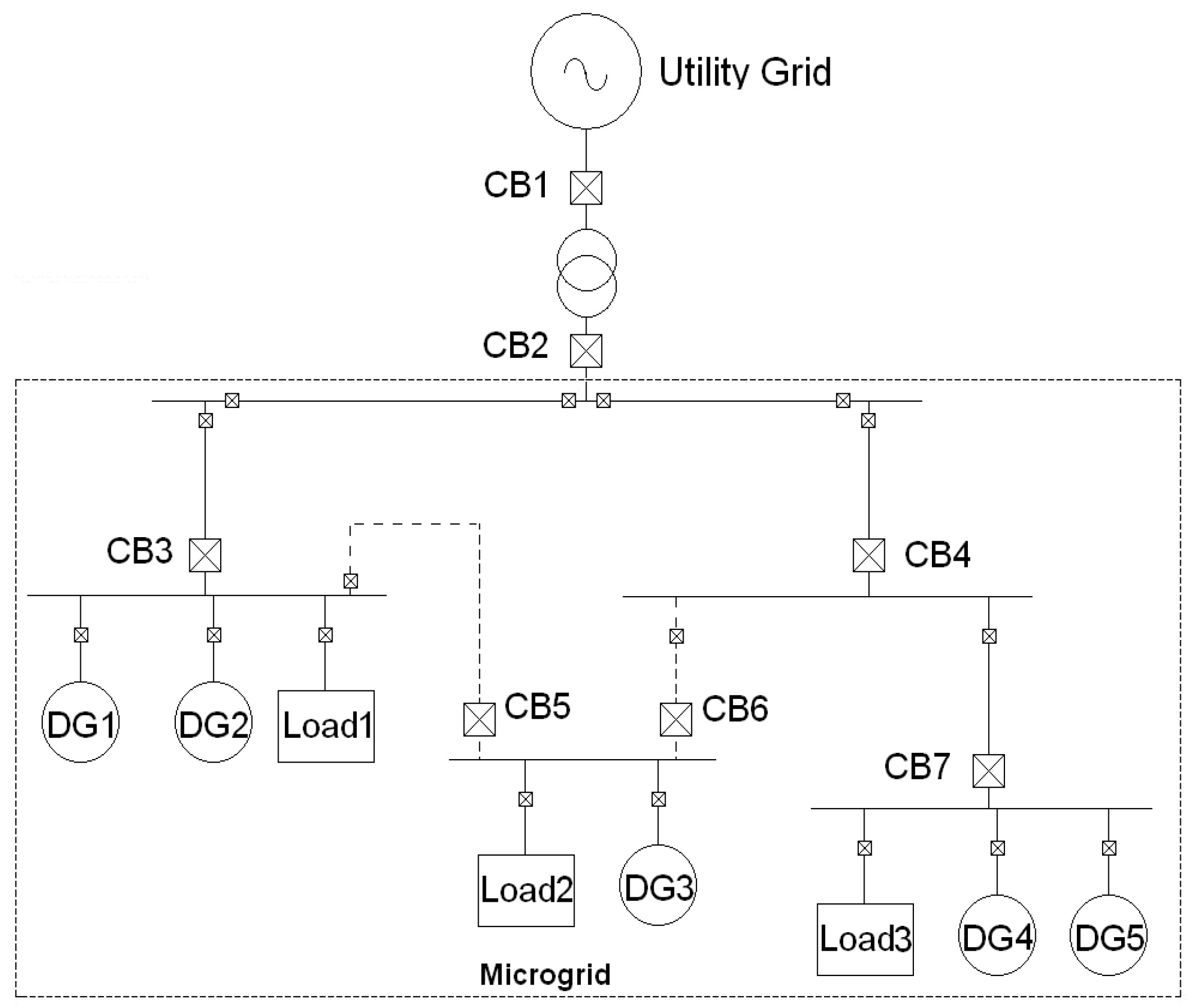
Introduction of microgrids and DGs changes this paradigm massively. Operating mode of the microgrid determines if there will be a fault contribution from the utility grid, and considering that it has the largest magnitude, it is vital to monitor this change. Alternative connections might be used in a microgrid and this causes a change in the upstream–downstream pairs for every different topology. These necessitate online monitoring of the microgrid operating conditions and update relay set points accordingly. A typical microgrid is depicted in Figure 2.
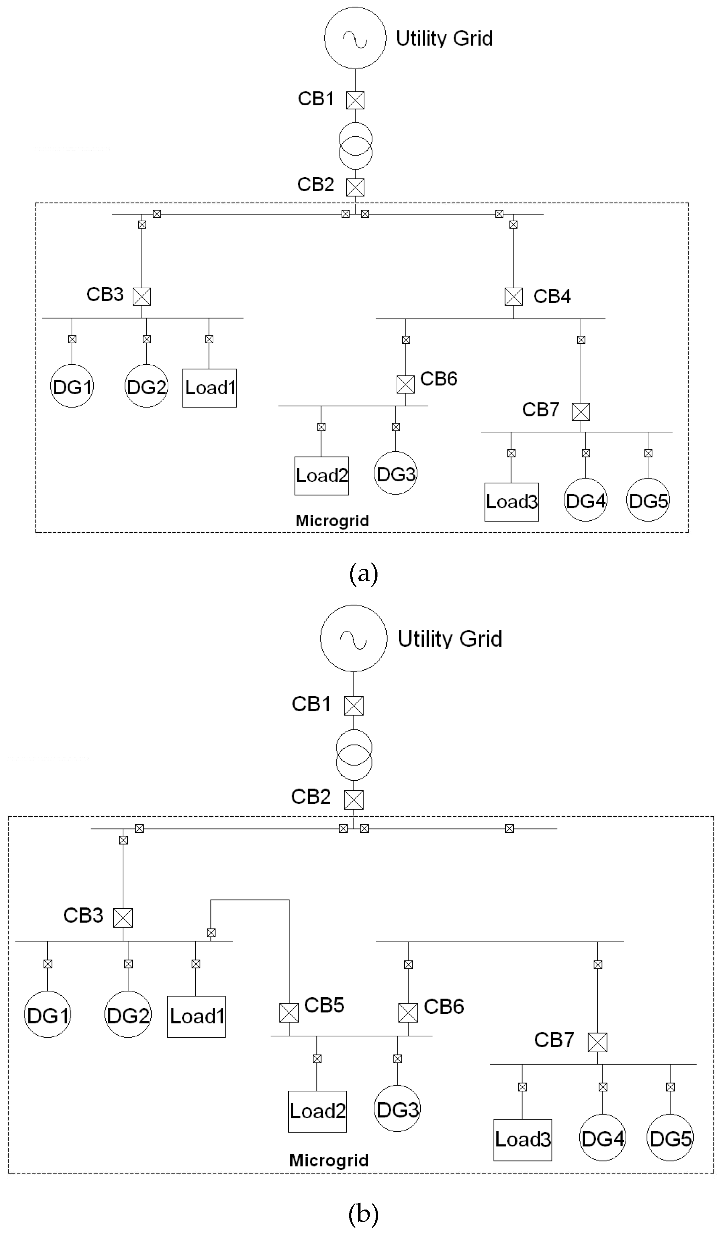
Different connection combinations, due to maintenance, dynamic changes, etc., can create different topologies such as those shown in Figure 3. In the first case (a), there are two distinct branches and, for instance, relay 3 and relay 7 are not associated since they are not in the same protection line. However, this completely changes when CB5 connects and CB4 disconnects. Suddenly relay 3, relay 5, relay 6, and relay 7 belong to the same protection line and become backup pair. Therefore, a system that detects these changes on-the-fly and update the protection settings is required.
There is a finite time, tclear, before which a fault must be cleared in the system. All protection interventions, including primary and backup, must take place within this period. Therefore, time delays between backup pairs are assigned as increments of a base value, tunit:
tunit = tclear/selective levels (n)
The most downstream relay is expected to operate immediately, while others should operate in a cascaded manner. Operation delay of a given relay in the system can be expressed as
trelay = tunit × selective level of relay (nrelay)
If a communication network is utilized to update these values in the devices, then the time required for the communication must be taken into account for protection against worst-case scenario, i.e., when a fault occurs just after the system starts updating its selective level calculations.
trelaycomm = trelay − tcomms
The focus of this paper is to develop an automated method that can extract the current topology of power network and transmit this information to the nodes. Updating the relay settings or their time delays is out of the scope of this paper. Detailed discussion on protection coordination challenges and how relay settings can be updated to ensure proper protection can be found in [18]. However, an important assumption made there is that the current structure of the power network is somehow known. This is an assumption most protection schemes rely on. The current manuscript aims at removing this assumption and making protection schemes more universal.
3. Mapping of Graph Theory on Electrical Networks
This paper takes graph theory concepts and uses them to solve the problems mentioned above. Abstracting the real-world power grids in terms of graphs helps us visualize different problems in distributed grids and, ultimately, solves those problems by leveraging the established research in graph theory and algorithms for solving graph problems.
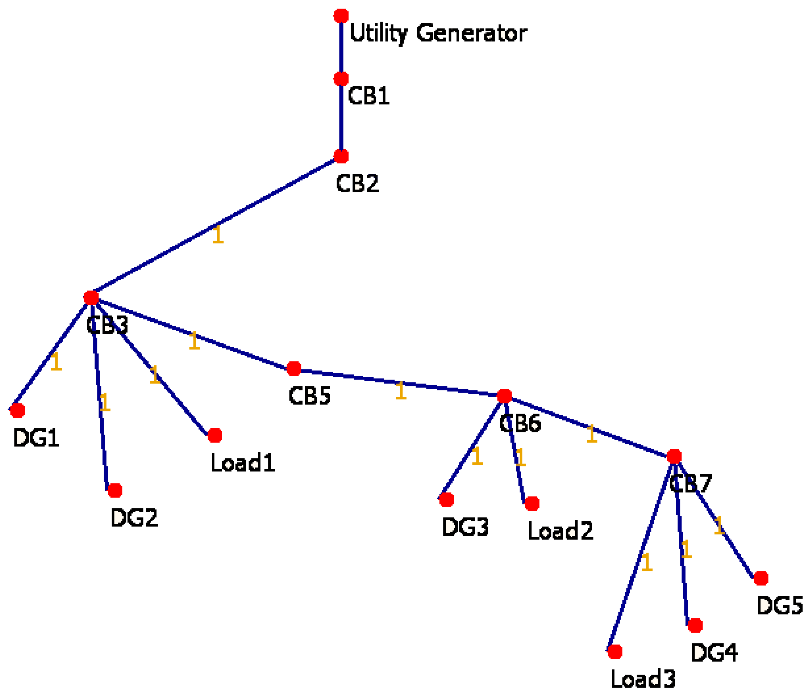
In order to find smart algorithms, electrical networks first needed to be mapped to graph theory concepts. Intuitively, an electrical network is mapped to the basic concept of a graph. An electrical network essentially consists of components and the connections between them, whereas, a graph G consists of a set of vertices V and a set of edges E. Here a simple mapping exists between the vertices in graph G and components in electrical network. Similarly, the edges in graph G are mapped to the connections in electrical network. As an example, the electrical network shown in Figure 3b can be represented by a graph as shown in Figure 4 [6].
Due to inherent nature of electrical networks, the graphs representing them have the following characteristics.
- 1-
- A graph abstraction of electrical network is always an undirected graph.
- 2-
- A graph abstraction of electrical network may or may not be in a connected form.
- 3-
- A graph abstraction of power grid in its ideal state will only be abstracted to one and only one spanning tree, i.e., an undirected connected graph without any cycles in it.
- 4-
- An abstraction of power grid with faults/disconnections will be abstracted to a forest of spanning trees. Where each disconnected subgraph is a spanning tree itself.
These characteristics are important considerations while further mapping the protection in electrical networks to specific graph theory concepts. They also play a significant role in developing and applying algorithms to the graphs.
4. Management of Network Hierarchy Data
Problem 1: The management of information about network hierarchy is important. In a centralized management scheme, a central repository holds the data table representing the network hierarchy, along with a matrix representing the connections between DGs, CBs, and Loads. Central repository leads to a single point of failure as well as hinders the plug-n-playability of the network. Any change in the network results in a need to update the information about the network hierarchy. In traditional setup, this information is updated manually.
Proposed Solution: Any change in the electrical network maps to either addition of a new node in the graph, or a loss of an existing edge. In case an existing edge is lost, due to the characteristic of graph being a sparse tree, the result is always a set of two or more subgraphs, which are sparse trees themselves. In order to maintain the network properly, after each change, the resulting graphs need to provide new network hierarchy to central controller.
This paper proposes algorithms for keeping the graph updated. This involves both the propagation of change information and exploration of new graph structure. These algorithms work on any arbitrary known node of the graph, therefore dependency on centralized maintenance of graph information is removed. The algorithms result in a graph representing complete network hierarchy. The graph algorithm works on the principle that all the nodes know and maintain a list of neighboring nodes. In case of any network change the graph, exploration algorithm can be run on any node, which will result in a complete discovery of the resulting new graph.
Disappearance of an edge or connection of a different edge should be updated in real-time data, if the system is run in real-time. This can be achieved with an already utilized communication network for power system, which is already becoming a staple component of novel systems [18].
Let there are two nodes A and B involved in a change in the graph. In case of change due to a new connection between A and B, both have up-to-date respective graphs. In case of single nodes these graphs will only contain themselves. Formally, each node is expected to have a copy of the graph G of which it itself is a part of. As per the definition of a graph, it consists of a set of vertices V and a set of edges E. Let VA and EA represent the copy of the graph at node A at the time of connection with node B. Similarly, let VB and EB represent the copy of the graph, node B is part of.
When the connection is made, both nodes A and B will merge VA and VB to form V as follows
V = VA U VB
Similarly, EA and EB will merge into E as follows
E = EA U EB
Once both the nodes are updated with the latest V and E, they propagate this information to other nodes in their respective parts of the graph with the help of the following algorithm. The algorithm has two parts, one is the initiation of the algorithm and the second is the update command. The initiation part of the algorithm runs, arbitrarily, on any one of the two nodes involved in the connection. The second part of the algorithm is run on rest of the nodes in the resulting graph. The update command is originated from the initial two nodes and then is propagated to the rest of the graph, ensuring that each node has a latest copy of the graph.
Update Initiation
- 1:
- Input: Local copy of G including E and V
- 2:
- 3:
- At node A
- 4:
- Create an empty set of initiators I
- 5:
- Set A as the initiator by adding A in the set I
- 6:
- From E find all the immediate neighbors of A
- 7:
- For each neighbor of A
- 8:
- Send Update(E, V, and I)
- 9:
- Wait for response
- 10:
- Replace local G with response
- 11:
- Broadcast G to all nodes in V
Update Action
- 1:
- Input: Update command (E,V,I)
- 2:
- 3:
- Set self as initiator and add self to set I
- 4:
- From E find all the immediate neighbors
- 5:
- For all the neighbors not present in I
- 6:
- Send Update(E, V, and I)
- 7:
- Wait for response
- 8:
- Repeat until V = I
- 9:
- If (V = I)
- 10:
- Return local G
As discussed earlier, when the cause of the change event is due to a broken connection between two nodes of the graph, we first need to establish that the change has happened, which can be done by either a direct message from the one of the vertices of the connection edge to other counterpart or it may be due to a failed ping. Assuming that an edge between two nodes, i.e., A and B, is broken, it is required to perform graph detection and update. Removal of an edge can make the graph to be split into two separate graphs each of which will now needs to update all their respective nodes with the new configuration. Since each node initiates a ping to each of its neighbors therefore in case of a broken connection both will have a failed ping and hence will initiate the update process.
The following algorithm is run on each node, referred to as ‘self’ in the algorithm, in V. This algorithm ensures that the latest copy of the graph is propagated to all the nodes in the graph.
Find Missing Node
- 1:
- Input: E, V
- 2:
- Find all immediate neighbors
- 3:
- For each neighbor
- 4:
- Send a ping message
- 5:
- Wait for acknowledgement
- 6:
- If (Acknowledgement Not Received in due time)
- 7:
- Mark the neighbor as missing
- 8:
- If (any neighbor missing)
- 9:
- Consider self as initiator and add self to a set I
- 10:
- Remove all the missing neighbors from E and V
- 11:
- From E find all the remaining immediate neighbors
- 12:
- For all the neighbors not present in I
- 13:
- Send Update(E, V, and I)
- 14:
- Repeat forever
As a result of these two algorithms, any change in the network hierarchy ends up propagating G, which represents the latest structure of electrical grid.
In order to tackle the extreme case where a node in the graph is known but there is no available information about the complete graph, this paper proposes an online graph exploration algorithm, which is based on the premise that any node internally stores the list of its immediate neighbors. Therefore, a complete graph can be extracted, even in chaotic situation, by using the following algorithm. The algorithm can be invoked at any arbitrary node of the graph. The algorithm has clearly two parts, one that is run on the known node, which handles sending the DiscoverGraph command to its neighbors, and the other part is run on its neighbors, who, in turn, both send and receive DiscoverGraph commands and responses to these commands.
Send DiscoverGraph Message
- 1:
- Input: Node n (self)
- 2:
- Output: Graph G
- 3:
- 4:
- Create an empty graph G̀
- 5:
- List all the neighbors of self as Vself
- 6:
- Add local information about connections to G̀
- 7:
- For each neighbor of self
- 8:
- Send DiscoverGraph message (G̀,self)
- 9:
- where G̀ is the new graph and self as the recipient of DiscoverGraph response
- 10:
- Wait (until all responses arrive)
- 11:
- Extract G from last response
Receive DiscoverGraph Message
- 1:
- Input: Node n as recipient of response
- 2:
- Input: Graph G of the sender
- 3:
- List all the immediate neighbors of self Vself
- 4:
- For each neighbor
- 5:
- If (neighbor is not already in G)
- 6:
- Add information of local connections to G
- 7:
- For all new additions in G
- 8:
- Send GraphDiscover (G,self)
- 9:
- If (There is no addition in G)
- 10:
- Send G back to node n
- 11:
- else
- 12:
- Wait (until all responses arrive)
- 13:
- Send the latest G back to node n
Extraction of relay hierarchy is required to apply selectivity appropriately. For this case, there is a single path between CB2 and the loads, DG1-2 and Load1-2. This special case simplifies to a path finding problem where Dijkstra’s algorithm is run to extract this path, rather than comparing it with others to find the shortest one.
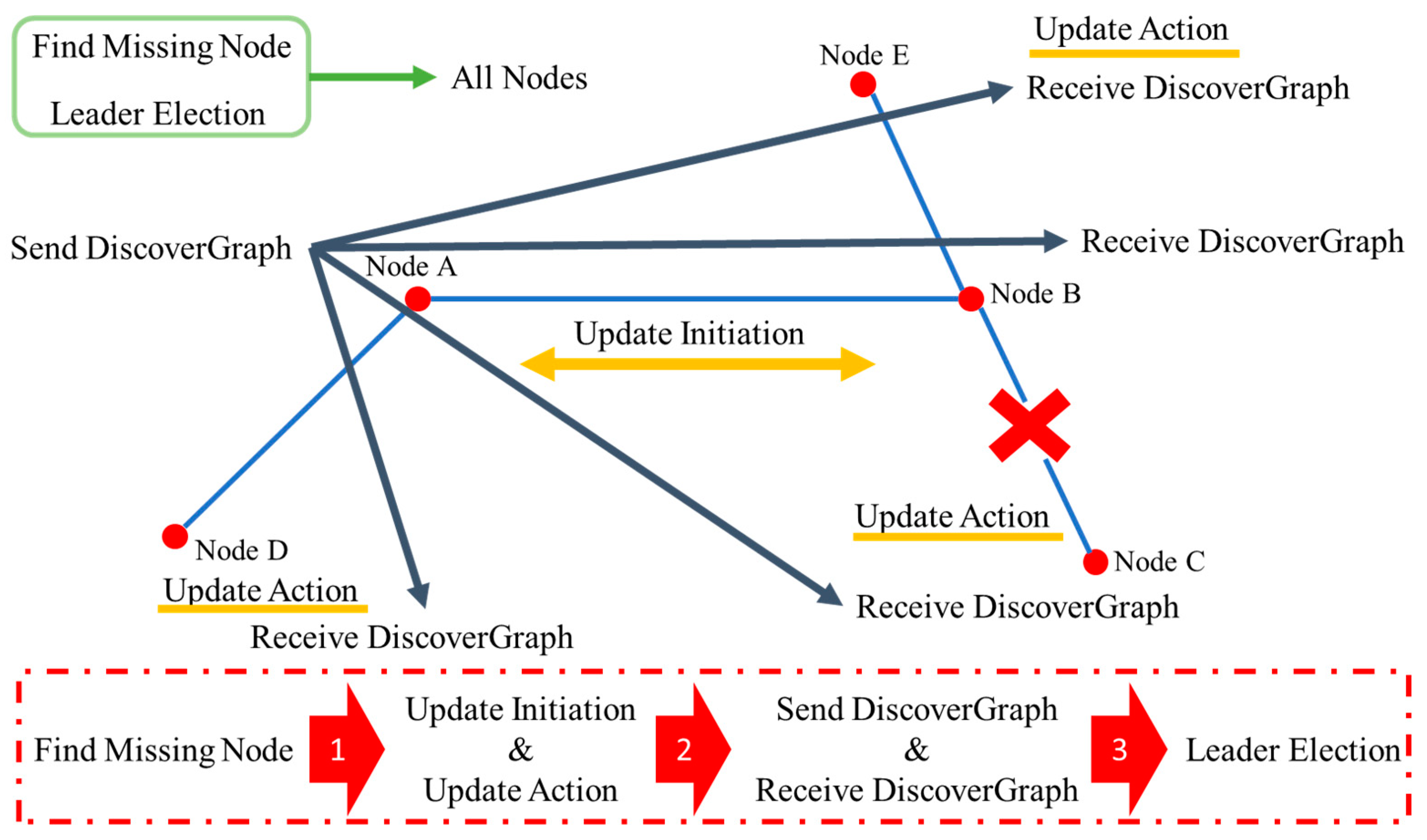
Consider the hierarchy of electrical network, as shown in Figure 3a, has just been transformed to a new hierarchy, as shown in Figure 3b. The resulting abstraction of the network is presented in Figure 4. In order for CB1 to find out the relay hierarchy by using the Dijkstra’ s shortest path algorithm, this new network structure is needed in the form of a graph. This graph becomes available when the proposed graph discovery algorithm is initiated at CB1. When the proposed algorithm is initiated at CB1, the following chain of events happens. Figure 5, below, shows how these different algorithms are initiated, and which nodes are involved.
- 1-
- CB1 runs the Send DiscoverGraph part of the algorithm
- 2-
- Utility Generator and CB2 are sent DiscoverGraph messages
- 3-
- CB2 and Utility Generator nodes run the Receive DiscoverGraph part of the algorithm
- 4-
- Since Utility Generator has no other neighbor than CB1, therefore it ends there.
- 5-
- CB2 has two neighbors CB1 and CB3. A further message is sent to all CB2 requesting it to DiscoverGraph. Since CB1 is the initiator of the DiscoverGraph algo therefore it is not sent a request again, thus avoiding an infinite loop.
- 6-
- CB3 has 5 neighbors CB2, DG1, DG2, Load1, and CB5. Since all, except CB5, are either terminal nodes or a relay that initiated the graph discovery algorithm, therefore a further request for graph discovery is propagated to CB5.
- 7-
- The same step applies to CB6 and CB7.
- 8-
- When CB7 is sent with a DiscoverGraph request and it does not have a further path to propagate the request, it returns the subgraph representing CB7 node and all its terminal nodes. This information is sent back to CB6 which updates its internal information about the network below CB7, and then propagates this information to CB5. So on and so forth.
- 9-
- Each response at CB7,CB6,CB5,CB3, and CB2 ensures that graph information below that relay is complete. Hence, when CB2 responds back to CB1, complete network hierarchy becomes known at CB1.
Once a complete graph is known at any node, Dijkstra’s shortest path algorithm can be used locally to find out the relay hierarchy from that node to any other node in the graph. The default value of the distance in these graphs is one. Since the algorithm is run to extract the path, hence, to detect the topology, any value can be utilized. However, unit distance is used in these studies, since it corresponds to the selectivity level and eases the calculations. The overall distance between two nodes, n in (2). Selective level of a particular relay corresponds to its distance to a node, i.e., nrelay in (3).
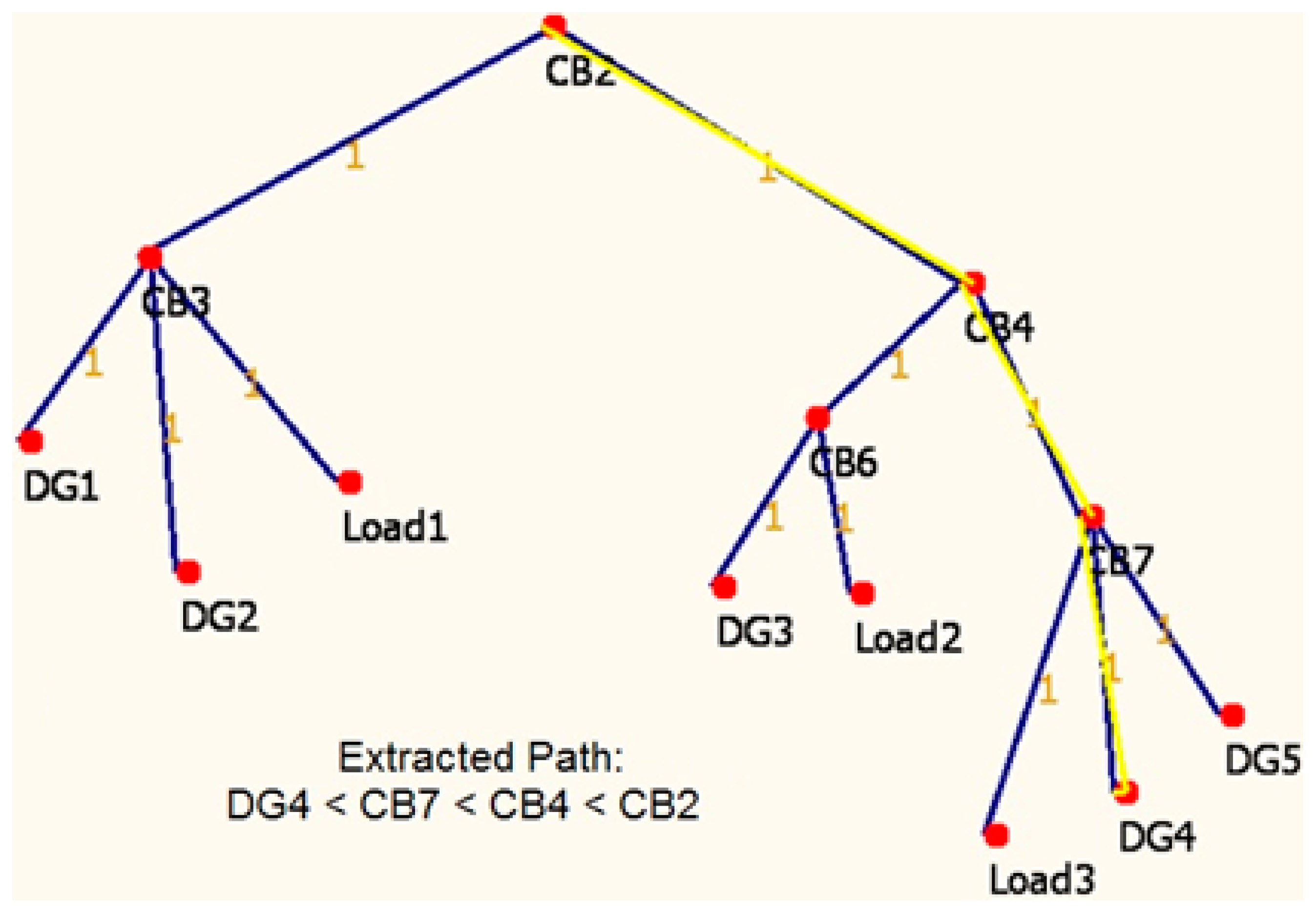
A computer program, developed in C# [30], is used to run and visualize Dijkstra’s algorithm on the modeled graphs of above power system. As shown in Figure 6, the nodes and edges are created, with unit distances. When it is run, the algorithm successfully finds and highlights the path between different nodes, i.e., DG4 and CB2 in this case. This is repeated with Case 2, as in Figure 3b, and the new route is found. Table 1 shows the distances and corresponding paths for both cases. The paths found between DG4 and CB2, third row from the bottom, are different, and in line with the topologies of cases 1 and 2. The strength of the proposed technique is that there is no need for a central unit or aggregator to monitor all these changes. Each node only talks to its neighboring nodes as it connects or disconnects. There is no universal monitoring of the system, yet individual connections are sufficient to recognize the changes between two nodes that are spread apart.
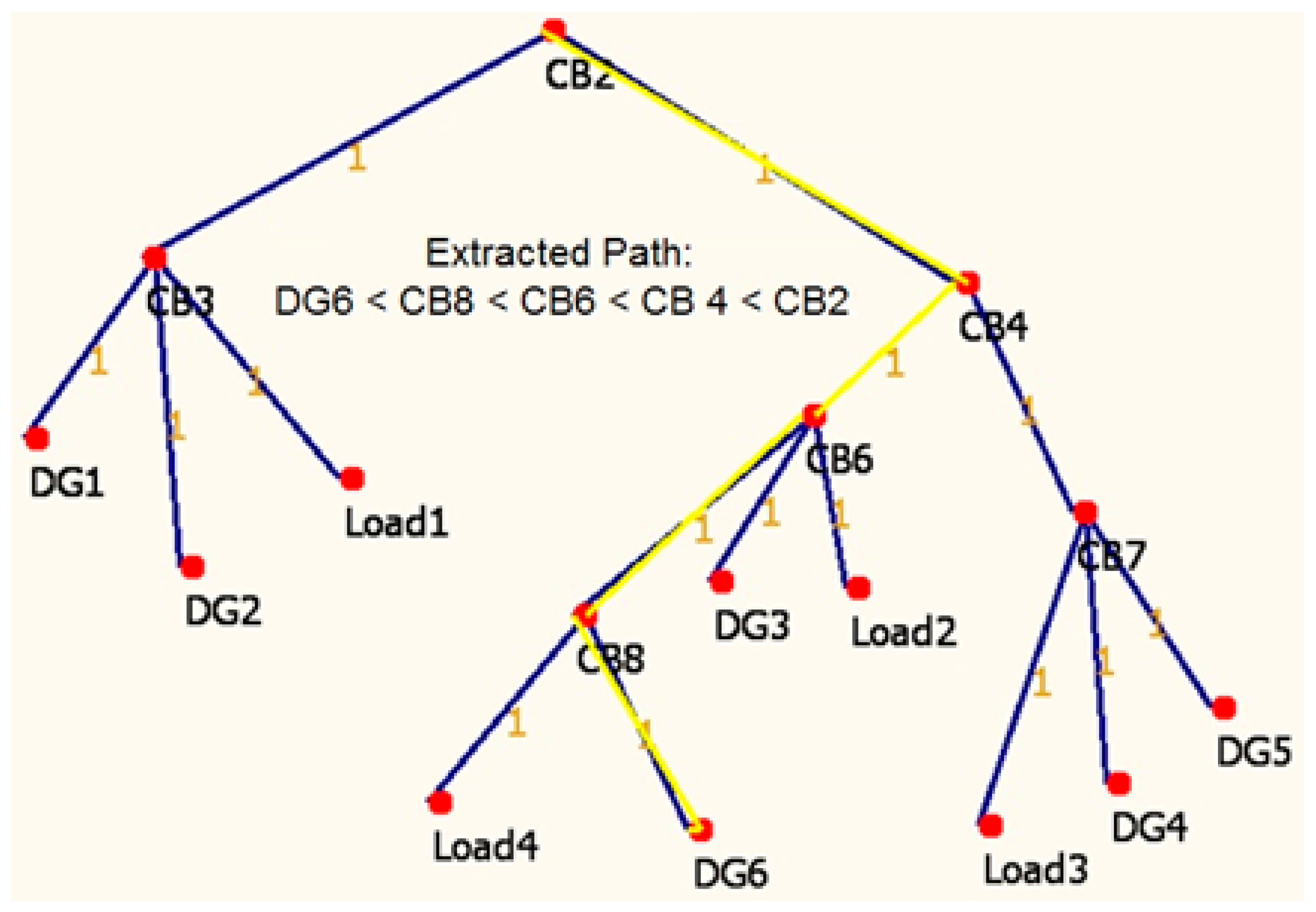
Another advantage of the developed solution is that the new deployments to the microgrid can be automatically detected. If a house owner decides to install PV panels on their roof, all they need to do is to report this to its neighboring node. As shown in Figure 7, a new DG or load connection is detected by the system without the need for a central aggregator or controller.
5. Distributed Microgrid Protection
In light of the above considerations, in this paper, the authors propose a Power System Management Scheme for Emergency Situations (PSMS-ES). The control and communication systems are critical in estimating the extent and scale of the disaster (or attack). If the entire power network is impaired, the proposed scheme is utilized to energize individual houses. If some power lines are still active, a small microgrid can be used and the energy is provided by local generation.
Problem 2: A predesigned rigid central controller setup is more prone to single point of failure. Therefore, a self-healing adaptive mechanism is needed that can scale-up or -down according to the situation.
Proposed Solution: This paper proposes a leader election algorithm, which will be utilized by all nodes in the graph to elect a leader. In terms of electrical network this leader can be mapped to a central controller. The basic idea behind this algorithm is to run it in parallel on all the nodes in graph G. Since all the nodes have discovered same graph G, using the algorithms presented above, therefore their results will be same. This ensures a leader node is elected unanimously without any ambiguity, race condition, or a deadlock. Given a graph G is available to all nodes in G; the following algorithm is executed for central controller election.
Leader Election Algorithm
- 1:
- Input: Graph G
- 2:
- Output: Leader Node
- 3:
- 4:
- For each node n in G
- 5:
- Using Dijkstra’s Shortest Path Algorithm
- 6:
- Find Shortest distances to all other nodes in G
- 7:
- 8:
- Let DSPn = {p1,p2,…,pn-1}.
- 9:
- {˅ pi ϵ DSPn|pi is a path from node n to node i}
- 10:
- 11:
- Let MAXn = Longest(DSPn)
- 12:
- MAXn is the length of the longest path pi ϵ DSPn
- 13:
- SHORTEST = Shortest(MAXi) for I = 1 to n
- 14:
- 15:
- Let LeadershipCandidates = { }
- 16:
- For each node n in G
- 17:
- If(MAXn = SHORTEST)
- 18:
- Add node n to LeadershipCandidates
- 19:
- Leader = LeaderShipCandidates.First
- 20:
- For all candidates C in LeadershipCandidates
- 21:
- If (Leader.ID < c.ID)
- 22:
- Leader = c
This algorithm does not require communication of local computations to other nodes. Similarly, it also minimizes the need for communication of the results. It is worthy to note here that calculating max over a range of numbers is a trivial operation, and is therefore is not presented in this paper. Similarly, selecting an element from a set with shortest value of an attribute (length of the path) is a trivial operation. Furthermore, in case of competition between more than one candidate for leadership, the tie breaker is based on the globally unique ID’s of nodes.
The time complexity analysis of Update and GraphDiscover algorithms results in a running time of O(N) where N is the total number of nodes present in the graph. As evident from the algorithms, they need to broadcast any change to all others, so an upper bound for number of messages sent is O(N). Even the Pings to neighbors does not require more than O(N) messages. Although, the Update and GraphDiscover algorithms can be seen as an adoption of Depth First Search which has a running time of O(|N| + |E|), where E is the total edges in the graph, but in case of electrical network there is only single edge between two nodes. Therefore, in total the time complexity of these algorithms is O(N).
Dijkstra’s algorithm is run for each node therefore it’s running time of O(E log N) becomes O(E N log N). Finding the Max path from a single node takes O(N) and by repeating for all nodes makes it run in O(N2). Eventually the SHORTEST of all Max paths can be found in O(N), and to find the leader in the list with the highest ID value will also require O(N) time. In total, a bound of O(N2) can be easily established.
To illustrate these bounds, let us take an example of 100 nodes (relays, loads, and generators). If one relay gets disconnected, the leftover system will need to send 100 messages to update it. If central controller disconnects then a new one is needed to be elected. With an election process of O(N2) order, there would be approximately 104 logical comparisons made at the most. A typical 1 MHz processor can run 106 instructions in just one second, which is 100 times more computing power than required to run this algorithm in 1 second. This is quite acceptable for grid restructuring and, especially, for postdisaster recovery when outside relief may not arrive for days, or even weeks.
6. Postdisaster Recovery Scheme for Microgrids
The developed method is showcased over the operation of power systems in emergency cases which is a very important topic. Realizing the importance of electrical power and the impacts of its loss, governments around the world have studied vulnerability of power systems to natural disasters and sabotage [31,32]. It is stated that operation and coordination of power systems in extreme weather conditions and acts of cyber and physical attacks are key elements for national emergency recovery. Recent incidents (such as Hurricanes Katrina as well as Fukushima Earthquake) clearly showed that there is not a well-developed plan for providing electrical power under emergency conditions. Continuous supply of power is essential to recover from the negative impacts of emergency cases. Regardless of this case being a natural disaster, sabotage, or open warfare, having electricity for basic needs of neighborhoods, community centers, and public services will be a crucial support for those who are affected.
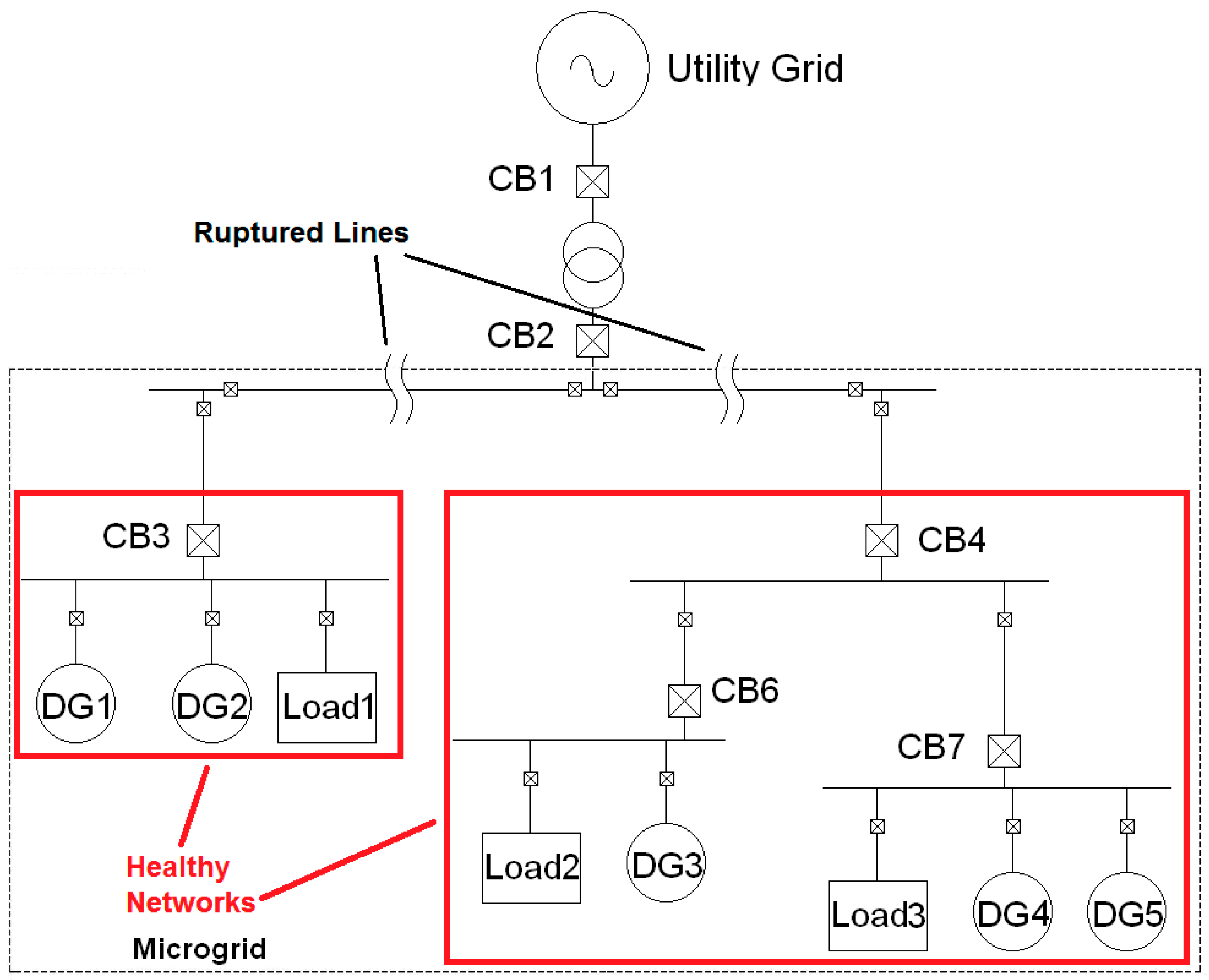
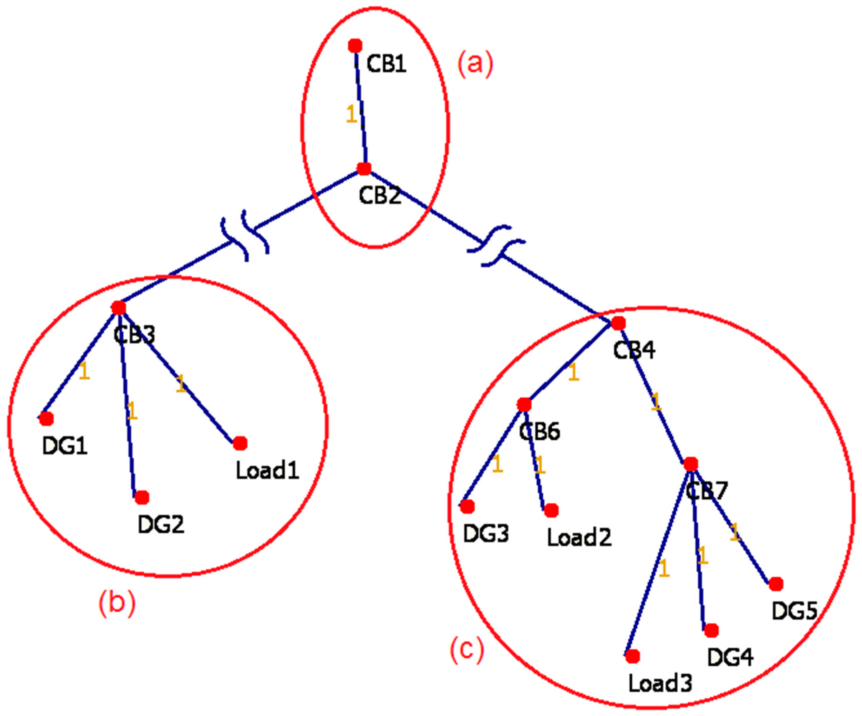
As shown in Figure 8, after a disaster strikes, such as a hurricane, some parts of the electrical grid may be damaged and regular operation cannot continue. To run the proposed algorithm of local central controller election both healthy parts of the network need to explore their local network and find out their corresponding graphs. Figure 9 shows three postdisaster healthy networks. Since the connections between CB2 and CB3 and CB2 and CB4 are lost, CB2, CB3, and CB4 will detect a change in network. Furthermore, if CB2 was acting as the central controller before the disaster then both, otherwise healthy parts of the network will be left leaderless. Since all nodes can detect the loss of their leader, therefore, all nodes will initiate their own copy of leader election algorithm.
To run the leader election algorithm, healthy parts of the network need their corresponding graphs. In order to update the network with the new information, CB3 and CB4 will initiate the update command algorithm. Table 2 and Table 3 show iterations of the algorithm at different nodes in each subgraph (healthy parts of network), this will result in a copy of corresponding subgraphs at initiating nodes.
Once the Update algorithm is finished, a broadcast of local copy of G is sent to all other nodes in the corresponding subgraph. In this case CB3 and CB4 initiated the Update command so they send a broadcast message to all other nodes in their corresponding graphs, with a copy of the complete subgraph. Hence in each healthy part of the network, as shown in Figure 9b,c, a copy of corresponding subgraph is available on each node.
Once the nodes are updated with the complete graph of their network, they are ready to run the local central controller with the help of the leader election algorithm proposed above. This algorithm is run on each node of the graph, and since each node contains the same copy as other nodes, the result of leader election algorithm is same for all nodes running the algorithm. In the example case, Figure 9b, node CB3 is elected to be the new local central controller.
Table 4 shows the leader election algorithm in action, with all the internal calculations. G represents the local graph and V is the set of vertices, while E is the set of edges. Source denotes the source node, Dest. is the destination node, Path shows the path traveled, and Length denotes the length of the path. Longest DSP is the longest length of any path originating from the source node to the destination by using the Dijkstra’s Shortest Path (DSP) algorithm. As shown on the right top corner of Table 4, the node with the shortest Longest DSP, deserves to be the leader as it is the closest node to all other nodes. In Figure 9b, CB3 is chosen to be the leader as it is the closest to all other nodes.
7. Conclusions
Power flow through alternative paths, new deployments, and other factors hinders the proper protection in microgrids. A novel method is required to monitor the microgrid structure and update selective operation of relays. A distributed control is preferred since this mitigates the disadvantages associated with central controller-based solutions. This research makes a significant contribution to literature by developing a new method for determining the topology and components of a microgrid in a distributed manner. This information is vital for relay hierarchy and appointing selective levels. The method models a microgrid according to graph theory and smart algorithms are utilized to extract the network topology automatically. This approach allows for new deployments and automatically includes them in the calculations. This feature is very crucial for plug-and-play purposes in electrical networks.
This method also contributes to postdisaster recovery and ensures that communities have continuous energy supply during emergencies with self-diagnosis and self-healing capabilities. The system relies on smart algorithms to successfully detect healthy parts of power grid and appoint a local manager to continue proper operation. The system rolls-back to normal operation once the emergency case is over.
Author Contributions
All authors contributed equally to this paper.
Funding
No funding to report.
Conflicts of Interest
The authors declare no conflict of interest.
References
- Jenkins, N. Embedded generation. Power Eng. J. 1995, 9, 145–150. [Google Scholar] [CrossRef]
- Aftab, M.A.; Hussain, S.M.S.; Ali, I.; Ustun, T.S. IEC 61850 and XMPP Communication Based Energy Management in Microgrids Considering Electric Vehicles. IEEE Access 2018, 6, 35657–35668. [Google Scholar] [CrossRef]
- Nadeem, F.; Hussain, S.; Tiwari, P.; Goswami, A.K. Comparative Review of Energy Storage Systems, Their Roles, and Impacts on Future Power Systems. IEEE Access 2019, 7, 4555–4585. [Google Scholar] [CrossRef]
- Ustun, T.S. Design and Development of A Communication-Assisted Microgrid Protection System; Victoria University: Melbourne, Australia, 2013. [Google Scholar]
- Maqbool, U.; Khan, U.A. Dynamic and Transient Analysis of a Wavelet-Based Protection Scheme for Smart Grids. In Proceedings of the 2018 International Conference on Electrical Engineering (ICEE), Lahore, Pakistan, 15–16 Febuary 2018; pp. 1–5. [Google Scholar]
- Ustun, T.S.; Hadbah, A.; Kalam, A. Interoperability and interchangeability considerations in microgrids employing IEC61850 standard. In Proceedings of the 2013 IEEE International Conference on Smart Energy Grid Engineering (SEGE), Oshawa, ON, Canada, 28–30 August 2013; pp. 1–5. [Google Scholar]
- Ustun, T.S.; Khan, R.H.; Hadbah, A.; Kalam, A. An adaptive microgrid protection scheme based on a wide-area smart grid communications network. In Proceedings of the 2013 IEEE Latin-America Conference on Communications, Santiago, Chile, 24–26 November 2013; pp. 1–5. [Google Scholar]
- Dong, Y.; Hou, J.; Zhang, J.; Wang, Y.; Wang, H. The research, design and practice of the online special protection systems. In Proceedings of the 12th IET International Conference on Developments in Power System Protection (DPSP 2014), Copenhagen, Denmark, 31 March–3 April 2014; pp. 1–4. [Google Scholar]
- Oudalov, A.; Fidigatti, A. Adaptive Network Protection in Microgrids, More Microgrids Europe. Available online: http://www.microgrids.eu/documents/519.pdf (accessed on 1 June 2019).
- Liu, Y.; Yu, R.; Zhang, L.; Jiang, D.; Chen, N.; Zhao, D. Research on Short-Circuit Currents Calculation Method Considering Dynamic Reactive Power Support of Renewable Energy Systems. In Proceedings of the 2018 2nd IEEE Conference on Energy Internet and Energy System Integration (EI2), Beijing, China, 20–22 October 2018; pp. 1–9. [Google Scholar]
- Yao, L.; Wu, J.; Xu, L.; Rahman, M.H. Studies of coordinated zone protection strategy for DC grid. In Proceedings of the 2016 IEEE 8th International Power Electronics and Motion Control Conference (IPEMC-ECCE Asia), Hefei, China, 22–26 May 2016; pp. 713–718. [Google Scholar]
- Aftab, M.A.; Hussain, S.M.S.; Ustun, T.S. Dynamic Protection of Power Systems with High Penetration of Renewables: A Review of the Traveling Wave Based Fault Location Techniques. Renew. Sustain. Energy Rev. 2019. in print. [Google Scholar]
- Khan, R.H.; Ustun, T.S.; Khan, J. Differential protection of microgrids over a WiMAX network. In 2013 IEEE International Conference on Smart Grid Communications (SmartGridComm); IEEE: Vancouver, BC, Canada, 2013; pp. 732–737. [Google Scholar]
- Ustun, T.S.; Ozansoy, C.; Zayegh, A. Simulation of communication infrastructure of a centralized microgrid protection system based on IEC 61850-7-420. In Proceedings of the 2012 IEEE Third International Conference on Smart Grid Communications (SmartGridComm), Tainan, Taiwan, 5–8 November 2012; pp. 492–497. [Google Scholar]
- Ok, Y.; Lee, J.; Choi, J. Coordination of over current relay for sudden rise of input energy in renewable power system. In Proceedings of the 2015 International Conference on Renewable Energy Research and Applications (ICRERA), Palermo, Italy, 22–25 November 2015; pp. 654–658. [Google Scholar]
- Ustun, T.S.; Ozansoy, C.; Zayegh, A. Extending IEC 61850-7-420 for distributed generators with fault current limiters. In Proceedings of the 2011 IEEE PES Innovative Smart Grid Technologies, Perth, Australia, 13–16 November 2011; pp. 1–8. [Google Scholar]
- Ustun, T.S.; Ozansoy, C.; Zayegh, A. Differential protection of microgrids with central protection unit support. In Proceedings of the IEEE 2013 Tencon-Spring, Sydney, Australia, 17–19 April 2013; pp. 15–19. [Google Scholar]
- Ustun, T.S.; Ozansoy, C.; Zayegh, A. Fault Current Coefficient and Time Delay Assignment for Microgrid Protection System with Central Protection Unit. IEEE Trans. Power Syst. 2013, 28, 598–606. [Google Scholar] [CrossRef]
- Ali, I.; Hussain, S.M.S.; Tak, A.; Ustun, T.S. Communication Modeling for Differential Protection in IEC-61850-Based Substations. IEEE Trans. Ind. Appl. 2018, 54, 135–142. [Google Scholar] [CrossRef]
- Koeln, J.P.; Alleyne, A.G. Stability of decentralized model predictive control of graph-based power flow systems via passivity. Automatica 2017, 82, 29–34. [Google Scholar] [CrossRef]
- Bharti, D.; De, M. A new graph theory based loss allocation framework for bilateral power market using diakoptics. Int. J. Electr. Power Energy Syst. 2016, 77, 395–403. [Google Scholar] [CrossRef]
- Guo, F.; Wen, C.; Mao, J.; Chen, J.; Song, Y. Distributed Cooperative Secondary Control for Voltage Unbalance Compensation in an Islanded Microgrid. IEEE Trans. Ind. Inf. 2015, 11, 1078–1088. [Google Scholar] [CrossRef]
- Ustun, T.S.; Ozansoy, C.; Zayegh, A. Implementation of Dijkstra’s Algorithm in a Dynamic Microgrid for Relay Hierarchy Detection. In Proceedings of the 2nd IEEE International Conference on Smart Grid Communications (SmartGridComm), Brussels, Belgium, 17–20 October 2011. [Google Scholar]
- Swathika, O.V.G.; Hemamalini, S. Prims-Aided Dijkstra Algorithm for Adaptive Protection in Microgrids. IEEE J. Emerg. Sel. Top. Power Electron. 2016, 4, 1279–1286. [Google Scholar] [CrossRef]
- Karagiannis, G.M.; Chondrogiannis, S.; Krausmann, E.; Turksezer, Z.I. Power Grid Recovery After Natural Hazard Impact, EUR 28844 EN; European Commission Report; European Union: Luxembourg, 2017. [Google Scholar]
- World Energy Council. The Road to Resilience—Managing and Financing Extreme Weather Risk; World Energy Council: London, UK, September 2015. [Google Scholar]
- Yuan, W.; Wang, J.; Qiu, F.; Chen, C.; Kang, C.; Zeng, B. Robust Optimization-Based Resilient Distribution Network Planning Against Natural Disasters. IEEE Trans. Smart Grid 2016, 7, 2817–2826. [Google Scholar] [CrossRef]
- Ustun, T.S.; Cali, U.; Kisacikoglu, M. Energizing Microgrids with Electric Vehicles during Emergencies—Natural Disasters, Sabotage and Warfare. In Proceedings of the 37th IEEE International Telecommunications Energy Conference (INTELEC), Osaka, Japan, 18–22 October 2015. [Google Scholar]
- Ustun, T.S.; Khan, R.H. Multiterminal Hybrid Protection of Microgrids Over Wireless Communications Network. IEEE Trans. Smart Grid 2015, 6, 2493–2500. [Google Scholar] [CrossRef]
- Faria, P. Shortest Path with Dijkstra and C#. 2009. Available online: http://bit.ly/1IcrCpi (accessed on 13 July 2013).
- Executive Office of the President. Economic Benefits of Increasing Electric Grid Resilience to Weather Outages; Executive Office of the President: Washington, DC, USA, 2013.
- UK Energy Research Centre (UKERC). Building a Resilient UK Energy System: Research Report. “UK Energy 2050”. 2009. [Google Scholar]
Figure 1.
Novel fault conditions in dynamic power systems.

Figure 2.
A sample microgrid.

Figure 3.
(a) The network structure when CB5 is open and CB4 is closed. (b) The network structure when CB5 closes and CB4 opens.
Figure 3.
(a) The network structure when CB5 is open and CB4 is closed. (b) The network structure when CB5 closes and CB4 opens.

Figure 4.
Modeling case Figure (b with graph theory).

Figure 5.
Sequence of algorithms for discovering power system topology.

Figure 6.
Dijkstra’s Algorithm run for case 1; path from CB2 to DG4.

Figure 7.
Dijkstra’s Algorithm after new deployments; path from CB2 to DG6.

Figure 8.
Detection of postdisaster healthy networks.

Figure 9.
Postdisaster healthy networks modeled with graph theory.


Table 1.
Path from “Circuit Breaker 2”.
| Case 1 | Case 2 | |||
|---|---|---|---|---|
| Node | Dist | Path | Dist | Path |
| CB3 | 1 | CB2-CB3 | 1 | CB2-CB3 |
| CB4 | 1 | CB2-CB4 | - | - |
| *DG1 | 2 | CB2-CB3-DG1 | 2 | CB2-CB3-DG1 |
| *DG2 | 2 | CB2-CB3-DG2 | 2 | CB2-CB3-DG2 |
| *Load1 | 2 | CB2-CB3-Load1 | 2 | CB2-CB3-Load1 |
| CB5 | - | - | 2 | CB2-CB3-CB5 |
| CB6 | 2 | CB2-CB4-CB6 | 3 | CB2-CB3-CB5-CB6 |
| CB7 | 2 | CB2-CB4-CB7 | 4 | CB2-CB3-CB5-CB6-CB7 |
| *DG3 | 3 | CB2-CB4-CB6-DG3 | 4 | CB2-CB3-CB5-CB6-DG3 |
| *Load2 | 3 | CB2-CB4-CB6-Load2 | 4 | CB2-CB3-CB5-CB6-Load2 |
| *DG4 | 3 | CB2-CB4-CB7-DG4 | 5 | CB2-CB3-CB5-CB6-CB7-DG4 |
| *DG5 | 3 | CB2-CB4-CB7-DG5 | 5 | CB2-CB3-CB5-CB6-CB7-DG5 |
| *Load3 | 3 | CB2-CB4-CB7-Load3 | 5 | CB2-CB3-CB5-CB6-CB7-Load3 |
* denotes the leaf nodes.
Table 2.
Application of update algorithm on CB3.
| Node | Algo Run | Neighbors Contacted | Local V | Local V at Initiator Node |
|---|---|---|---|---|
| CB3 | Update Initiate | DG1,DG2, Load1 | DG1,DG2, Load1,CB3 | DG1,DG2,Load1,CB3 |
| DG1 | Update Action | none | CB3 | DG1,DG2,Load1,CB3 |
| DG2 | Update Action | none | CB3 | DG1,DG2,Load1,CB3 |
| Load1 | Update Action | none | CB3 | DG1,DG2,Load1,CB3 |
Table 3.
Application of update algorithm on CB4.
| Node | Algo Run | Neighbors Contacted | Local V | Local V at Initiator Node |
|---|---|---|---|---|
| CB4 | Update Initiate | CB6, CB7 | CB4,CB6,CB7 | CB4,CB6,CB7 |
| CB6 | Update Action | DG3, Load2 | CB4,CB6, DG3,Load2 | CB4,CB6,CB7,DG3,Load2 |
| DG3 | Update Action | none | DG3,CB6 | CB4,CB6,CB7 |
| Load2 | Update Action | none | Load2,CB6 | CB4,CB6,CB7 |
| CB7 | Update Action | Load3,DG4,DG5 | CB4,CB7, Load3,DG4, DG5 | CB4,CB6,CB7,DG3,Load2, Load3, DG4, DG5 |
| Load3 | Update Action | none | Load3,CB7 | CB4,CB6,CB7,DG3,Load2 |
| DG4 | Update Action | none | DG4,CB7 | CB4,CB6,CB7, DG3,Load2 |
| DG5 | Update Action | none | DG5,CB7 | CB4,CB6,CB7, DG3,Load2 |
Table 4.
Application of update algorithm on CB3.
| Graph | G | SHORTEST (Longest DSP) | 1 | |
| V | CB3,DG1,DG2,Load1 | Leadership Candidate | CB3 | |
| E | CB3-DG1,CB3-DG2,CB3-Load1 | Leader | CB3 | |
| Source | Dest | Paths | Length | Longest DSP |
| CB3 | DG1 | CB3-DG1 | 1 | 1 |
| CB3 | DG2 | CB3-DG2 | 1 | |
| CB3 | Load1 | CB3-Load1 | 1 | |
| DG1 | CB3 | DG2-CB3 | 1 | 2 |
| DG1 | DG2 | DG1-CB3-DG2 | 2 | |
| DG1 | Load1 | DG1-CB3-Load1 | 2 | |
| DG2 | CB3 | DG2-CB3 | 1 | 2 |
| DG2 | DG1 | DG2-CB3-DG1 | 2 | |
| DG2 | Load1 | DG2-CB3-Load1 | 2 | |
| Load1 | CB3 | Load1-CB3 | 1 | 2 |
| Load1 | DG1 | Load1-CB3-DG1 | 2 | |
| Load1 | DG2 | Load1-CB3-DG2 | 2 | |
Table 5.
Leader election algorithm in network C.
| Graph | G | SHORTEST (Longest DSP) | 2 | |
| V | CB4,CB6,CB7,DG3,Load2,Load3,DG4,DG5 | Leadership Candidate | CB4 | |
| E | CB4-CB6,CB4-CB7,CB6-DG3, CB6-Load2, CB7-Load3, CB7-DG4, CB7-DG5 | Leader | CB4 | |
| Source | Dest | Paths | Length | Longest DSP |
| CB4 | CB6 | CB4-CB6 | 1 | 2 |
| CB4 | Load2 | CB4-CB6-Load2 | 2 | |
| CB4 | Load3 | CB4-CB7-Load3 | 2 | |
| … | … | … | … | … |
| CB6 | CB4 | CB6-CB4 | 1 | 3 |
| CB6 | Load3 | CB6-CB4-CB7-Load3 | 3 | |
| … | … | … | … | …. |
| CB7 | DG5 | CB7-DG5 | 1 | 3 |
| CB7 | Load2 | CB7-CB4-CB6-Load2 | 3 | |
| CB7 | Load3 | CB7-Load3 | 1 | |
| … | … | … | … | … |
| DG3 | CB6 | DG3-CB6 | 1 | 4 |
| DG3 | Load3 | DG3-CB6-CB4-CB7-Load3 | 4 | |
| … | … | … | … | … |
| Load2 | CB7 | Load2-CB6-CB4-CB7 | 3 | 4 |
| Load2 | Load3 | Load2-CB6-CB4-CB7-Load3 | 4 | |
| … | … | … | … | … |
| Load3 | CB6 | Load3-CB7-CB4-CB6 | 3 | 4 |
| Load3 | Load2 | Load3-CB7-CB4-CB6-Load2 | 4 | |
| … | … | … | … | … |
| DG4 | DG3 | DG4-CB7-CB4-CB6-DG3 | 4 | 4 |
| DG4 | Load3 | DG4-CB7-Load3 | 2 | |
| … | … | … | … | … |
| DG5 | CB7 | DG5-CB7 | 1 | 4 |
| DG5 | Load2 | DG5-CB7-CB4-CB6-Load2 | 4 | |
| DG5 | Load3 | DG5-CB7-Load3 | 2 | |
© 2019 by the authors. Licensee MDPI, Basel, Switzerland. This article is an open access article distributed under the terms and conditions of the Creative Commons Attribution (CC BY) license (http://creativecommons.org/licenses/by/4.0/).
Share and Cite
MDPI and ACS Style
Ustun, T.S.; Ayyubi, S. Automated Network Topology Extraction Based on Graph Theory for Distributed Microgrid Protection in Dynamic Power Systems. Electronics 2019, 8, 655. https://doi.org/10.3390/electronics8060655
AMA Style
Ustun TS, Ayyubi S. Automated Network Topology Extraction Based on Graph Theory for Distributed Microgrid Protection in Dynamic Power Systems. Electronics. 2019; 8(6):655. https://doi.org/10.3390/electronics8060655
Chicago/Turabian StyleUstun, Taha Selim, and Saqib Ayyubi. 2019. "Automated Network Topology Extraction Based on Graph Theory for Distributed Microgrid Protection in Dynamic Power Systems" Electronics 8, no. 6: 655. https://doi.org/10.3390/electronics8060655
Note that from the first issue of 2016, this journal uses article numbers instead of page numbers. See further details here.