3D Multi-Beam and Null Synthesis by Phase-Only Control for 5G Antenna Arrays


Department of Engineering and Architecture, University of Trieste, Via A. Valerio 10, 34127 Trieste, Italy
*
Author to whom correspondence should be addressed.
Electronics 2019, 8(6), 656; https://doi.org/10.3390/electronics8060656
Submission received: 5 May 2019
/
Revised: 30 May 2019
/
Accepted: 8 June 2019
/
Published: 11 June 2019
(This article belongs to the Special Issue Recent Advances in Array Antenna and Array Signal Processing)
Abstract
:This paper presents an iterative algorithm for the synthesis of the three-dimensional (3D) radiation pattern generated by an antenna array of arbitrary geometry. The algorithm is conceived to operate in fifth-generation (5G) millimeter-wave scenarios, thus enabling the support of multi-user mobile streaming and massive peer-to-peer communications, which require the possibility to synthesize 3D patterns with wide null regions and multiple main beams. Moreover, the proposed solution adopts a phase-only control approach to reduce the complexity of the feeding network and is characterized by a low computational cost, thanks to the closed-form expressions derived to estimate the phase of each element at the generic iteration. These expressions are obtained from the minimization of a weighted cost function that includes all the necessary constraints. To finally check its versatility in a 5G environment, the developed method is validated by numerical examples involving planar and conformal arrays, considering desired patterns with different numbers of main beams and nulls.
1. Introduction
Multi-antenna technology has had a very long history since the first antenna array was developed more than one century ago [1]. Along the years, arrays have been exploited for different purposes, including electronic beamsteering, interference suppression, direction of arrival estimation, gain/directivity increase, transmission/reception diversity, and spatial multiplexing [2,3,4,5,6,7,8]. This wide set of applications makes antenna arrays one of the key components of forthcoming communication systems, from nanosatellite swarms to 5G cellular networks, with the aim of allowing the actual realization of the Internet of Things (IoT) and Internet of Everything (IoE) paradigms. One of the main reasons for the employment of multiple antennas for last generation communications is the choice, performed by network designers, of exploiting the millimeter-wave (mmWave) domain, which provides a large amount of unused spectrum. This choice enables the adoption of radiators of reduced size that, in turn, allows the installation of high-gain multi-antenna systems on the network devices in order to compensate the significant mmWave channel attenuations.
Basically, the design of an antenna array has to deal with two main problems: the development of the physical system (i.e., the geometry of the array and the selection of the radiating elements) [9,10], and the evaluation of the excitations that better satisfy the pattern synthesis requirements [11,12]. For this second task, several algorithms have been developed considering the geometry of the array, the shape of the desired pattern, and the degrees of freedom that characterize the array excitations [13,14,15]. However, when the array has to be mounted on a 5G base station (BS) or on a user device, some more specific constraints must be taken into account. Firstly, the beamforming algorithm must be able to perform beamsteering both in the azimuth and zenith domains, thus allowing a three-dimensional (3D) pattern synthesis. This requirement derives from the dimension of the 5G cells, whose radii are expected to be not larger than a few hundred meters [16], which makes situations where a source and a destination lie overground or underground relative to one another likely. Interesting solutions addressing this aspect have been developed by considering the synthesis of both the amplitudes and the phases of the array excitations [17,18,19]. Unfortunately, this choice does not match a second relevant constraint that characterizes the beamforming network of a 5G device: its simplicity. The feeding network must, in fact, be as simple as possible, since the ultra-densification strategy adopted for the 5G cellular system implies the deployment of a huge number of BSs that have to necessarily satisfy stringent cost requirements [20]. This suggests the usage of a phase-only control approach for the synthesis of the excitations, whose amplitudes hence have to be left constant and identical to avoid the installation of expensive power dividers. The development of phase-only synthesis techniques has been widely investigated, and thus a large number of solutions are already present [21,22,23,24,25,26,27], whose testing, except for [27], has been focused on the two-dimensional (2D) scenario. In this context, an interesting 3D clustered approach has been proposed in [28], where the array elements belonging to a cluster are characterized by a common amplitude and different phases. The support of massive device-to-device communications leads to a third constraint: the capability of generating radiation patterns with properly shaped null regions to selectively reduce the interference towards the active peer-to-peer links [8]. In this case, several proposals also already exist [21,22,23,24,25,26,29,30], but their analysis has again often been limited to the 2D environment. Finally, 5G developers aim to enable multi-user mobile streaming for serving multiple distributed mobile users in a cell [31]. This novel functionality has to rely on multibeam patterns, capable of generating multiple independent directional high-gain beams to cover different angular regions. Methods allowing the synthesis of multiple main lobes and also enabling null placement by phase-only control have been proposed [24,25,26], but still solely for the 2D scenario. In consequence, the satisfaction of all of the four discussed requirements invites the development of an array-processing algorithm able to perform multi-beam and null steering by phase-only control, simultaneously operating both in the zenith and azimuth domains.
To address this issue, this paper proposes an iterative method to synthesize the 3D pattern generated by an antenna array of arbitrary geometry with the sole modification of the excitation phases when multiple main lobes and nulls are required. The algorithm relies on the generalization of the 2D approach in [26], which is extended to operate in 3D scenarios also in the presence of wide null regions and is applied to planar and conformal arrays. The proposed method is developed by moving from a weighted cost function that accounts for the different constraints and is iteratively minimized. One of the main advantages of this method is the availability of closed-forms for evaluating the phase of each element at each iteration, which maintains the computational cost of the algorithm low. Numerical examples are presented to check the performance of the conceived solution and to prove its versatility in managing different synthesis problems.
The paper is organized as follows. Section 2 formulates the problem. Section 3 presents the algorithm. Section 4 discusses the results. Section 5 summarizes the main conclusions.
Notation. Throughout the paper the following notation is used: denotes the transpose operator, denotes the complex conjugate, j denotes the imaginary unit, and denotes the argument function.
2. Problem Formulation
Let us consider a Cartesian reference system to identify the positions of the N elements of an antenna array. The location of the generic n-th element () is described by the vector , where , , and denote the unit vectors of the coordinate axes x, y, and z, respectively. Accordingly, the unit vector describing the generic space direction is given by:
where and denote the zenith and azimuth angles, respectively. The far-field radiation pattern generated by this array can hence be expressed as
where is the column vector of the complex excitations, is the pattern of the n-th element, and is the wave number, with representing the wavelength.
Consider now the problem of synthesizing (2) assuming equal amplitudes for all the excitation currents (i.e., phase-only control), which implies , with () denoting the phase of the n-th element. The synthesis has to be carried out satisfying three requirements for the squared amplitude of (2), consisting in: (a) the presence of P maxima in the set of directions , with (); (b) the generation of Q nulls in the set of directions , with (); and (c) the maintenance of low values in the set of the remaining directions . From a mathematical point of view, the objective is hence that of estimating the excitation vector such that:
where the modulus is conventionally defined as
In particular, condition (3a) imposes the P desired directions, condition (3b) imposes the Q undesired directions, condition (3c) imposes the minimum possible radiation in the remaining directions, and finally, condition (3d) imposes the constraint concerning the phase-only control. The algorithm developed to solve this problem is presented in the next section.
3. Algorithm
A versatile approach to take into account the above discussed requirements consists in joining them into a cost function that contains selectable weights, which can be suitably modified in adherence to the specifications of a given problem [5]. However, a further basic aspect that should be considered when multibeam patterns must be synthesized is the equalization of the gains corresponding to the P directions of maxima. Thus, beside the terms deriving from (3a)–(3c), the cost function should include a further term having the objective of reducing the difference between the gains achieved in different desired directions. In agreement with these observations, we hence consider the minimization of the following weighted cost function:
in which the real parameters are proper non-negative weights. In particular, in (5), the minimization of the first term has the purpose of forming the P required maxima, while the minimization of the second term aims to guarantee that the difference between the amplitudes corresponding to these maxima is sufficiently low. Hence, the first two terms jointly impose condition (3a), in order to obtain an identical radiation level for all the P desired directions. The minimization of the third term aims to form the Q required nulls, thus imposing condition (3b), and finally, the minimization of the last term, identified by the integral, allows one to maintain the generated pattern as low as possible in the other directions, thus imposing condition (3c). By inserting (2) in (5) and using (4), after some algebra, can be expressed in compact form as
where
in which
Each of the four terms in (8) may be viewed as the generic component of an matrix. Thus, we can define the matrices , , , and , which are all Hermitian, since it can be easily proved that , , , and . This, in turn, implies that the matrix is also Hermitian.
Let us now impose condition (3d) according to which becomes a function of the sole set of phases . Therefore, recalling that , (6) can be rewritten considering its upper triangular elements as
the minimization of this function cannot be accomplished in closed-form, thus an iterative procedure is required.
This procedure can be inferred from the single co-ordinate method [21], which performs the minimization process through the calculation of the unknown phases one at a time, following a sequential order. Accordingly, (9) is minimized by individually evaluating each of the N unknown phases, assuming the other phases as constants. To allow this operation, the cost function is rearranged to put into evidence its dependence on the generic phase , thus obtaining
where
is a term independent of . A further manipulation of (10) leads to
where
It can be immediately observed that the final expression in (12) is minimized for
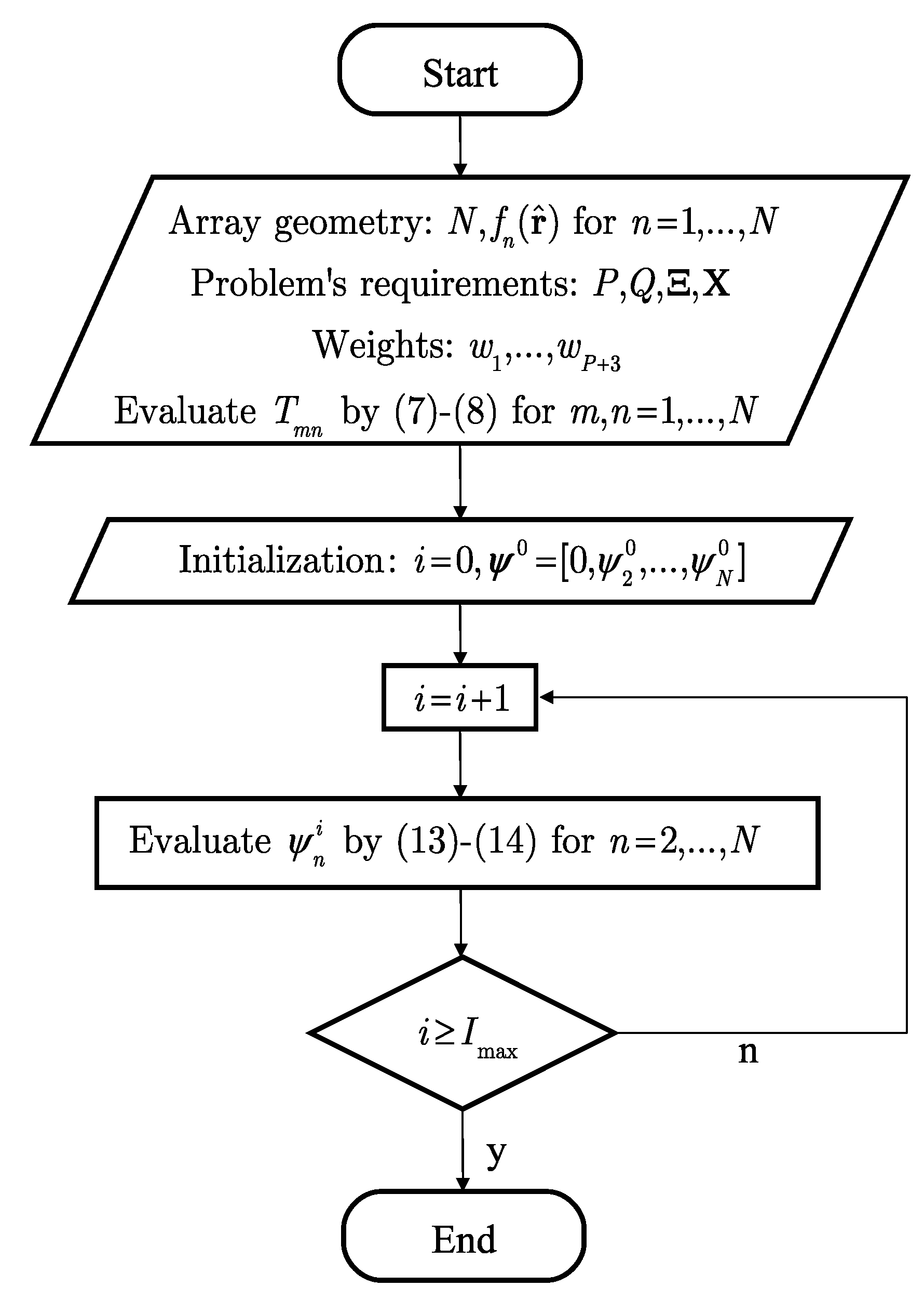
Thus, the generic unknown phase that minimizes can be evaluated in closed form. This advantage can be exploited to design an iterative algorithm to solve the original 3D synthesis problem described in Section 2. The proposed algorithm develops as follows (Figure 1).
First, given the formulated problem (i.e., the antenna array, the sets of desired and undesired directions, and the weights of the cost function), the elements of the matrix are calculated by (7) and (8). The starting point is then selected. Its first component, that is, , is taken as the reference phase, thus its value is maintained equal to zero for the entire evolution of the algorithm. Subsequently, the second element of is modified by using (13) and (14), while keeping constant all the remaining phases of . This leads to the updated value . By using the novel set , the same operation is carried out to update the third phase . This procedure is sequentially repeated until the last element is updated, thus concluding the first iteration of the algorithm, which provides an updated set . Proceeding in this way, at the generic i-th iteration, the last elements of are updated to obtain . Therefore, each iteration consists of subiterations necessary to update the phases different from the reference one. Since the cost function is minimized at each step, the algorithm generates a non-increasing, and hence convergent, sequence , where . The iterative procedure is terminated when the maximum allowed number of iterations is reached.
4. Results
The performance achievable by the conceived method is tested considering four numerical examples that are developed assuming isotropic antenna elements and a working frequency of 28 GHz [16], corresponding to a wavelength mm. The results are derived using the Matlab R2018b tool, which is installed on a personal laptop equipped with an Intel(R) Core(TM) i5-5300U [email protected] GHz processor and 8 GB RAM. For all the presented examples, the maximum number of iterations has been set equal to 4000.
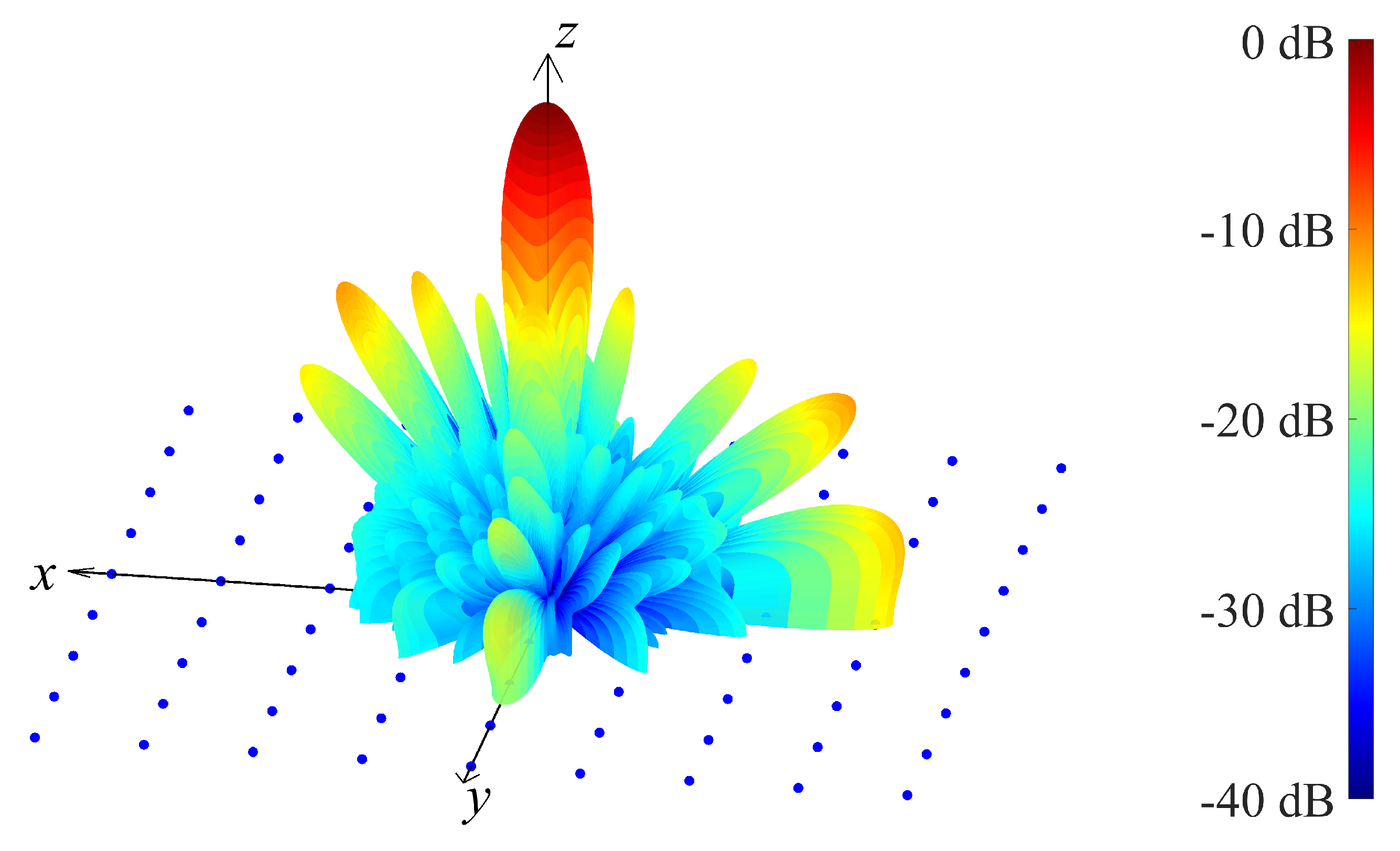
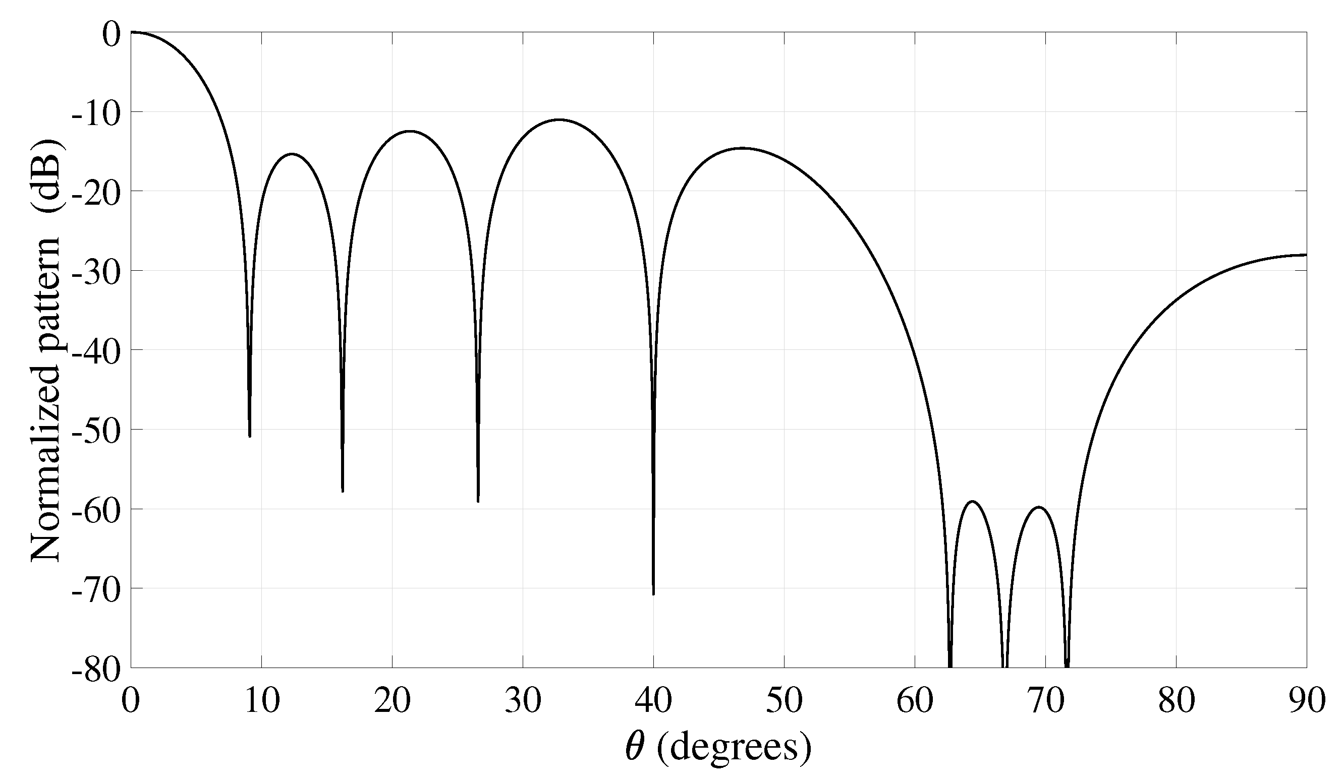
The first example refers to a 9 × 9 uniform square array with an interelement spacing equal to [9]. This implies that the array side is lower than 7 cm, making it suitable for usage on typical commercial smartphones. The desired pattern is characterized by a single main beam () directed at (broadside direction) and two null regions: a notch at and a wide null obtained by imposing four close notches at for , resulting in overall nulls. The 3D pattern synthesized by selecting the weights , , , and is reported in Figure 2, while the corresponding 2D cut at is shown in Figure 3. As it may be seen from this latter figure, the notch is exactly placed at , and the pattern amplitude is maintained close to −60 dB in the angular region identified by the wide null. Moreover, the side lobe level (SLL) of the overall pattern is kept below −10 dB, and interestingly, the entire 3D synthesis procedure is accomplished in approximately 5 s.
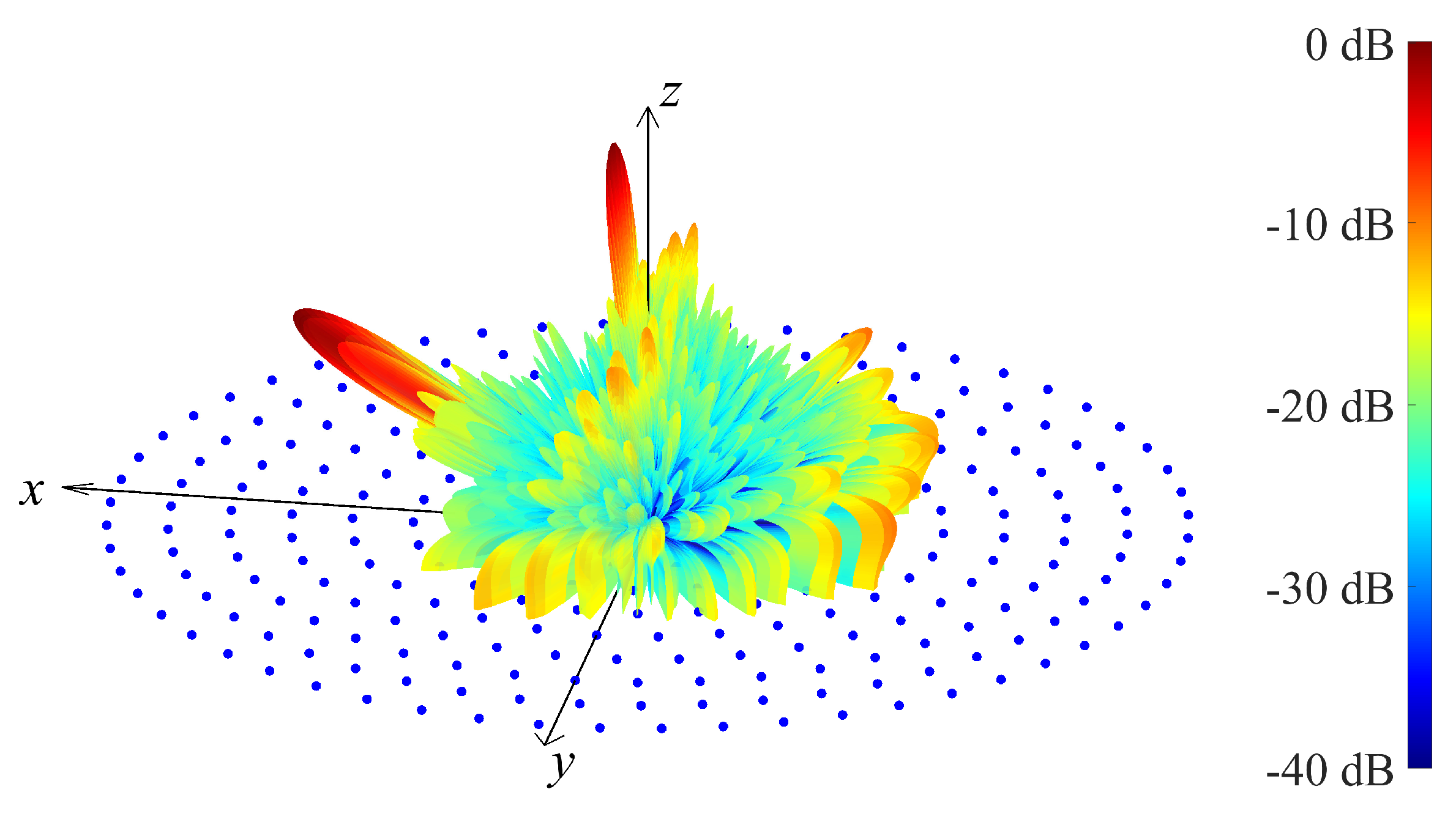
The second and the third examples refer to a larger array suitable for a compact 5G BS. The array consists of elements placed on concentric rings, lying on the plane and having the center at the origin of the Cartesian system. In particular, the nine rings have radii mm, mm, mm, mm, mm, mm, mm, mm, and mm and consist of , , , , , , , , and elements, respectively. These values have been chosen to guarantee a minimum interelement distance not lower than . Using this radiating structure, the second example is developed by considering a desired pattern with two main beams () directed at and , together with a wide null region, obtained by regularly spacing notches at for . The 3D pattern derived by choosing the weights , , , and is plotted in Figure 4, while the corresponding 2D cut at is reported in Figure 5. These two figures confirm the satisfactory behavior achieved by the proposed method, which guarantees the support of the required dual-beam pattern maintaining an SLL below −10 dB and a −50 dB level in the imposed wide null region. Moreover, also in this case the results have been obtained in an acceptable CPU time, since approximately 48 s was sufficient to complete the 3D synthesis procedure.
The third example refers to the same multi-ring array used for the previous example, but considering a more challenging scenario with main beams and two wide nulls. More precisely, the maxima are imposed at , , and , while the null regions are obtained by placing three notches at for and another three at for , resulting in overall nulls. The 3D pattern calculated by adopting the weights , , , , and is shown in Figure 6, while the corresponding 2D cuts at and are depicted in Figure 7a,b, respectively. This example reveals that also in the presence of more stringent requirements involving multiple main beams and wide nulls, the desired constraints are properly matched. The CPU time necessary to obtain this result is approximately equal to 48 s, almost identical to that of the previous example. This is reasonable, since the maximum number of iterations is fixed, and hence the CPU time becomes directly dependent on the number of elements, which is the same for the second and third examples.
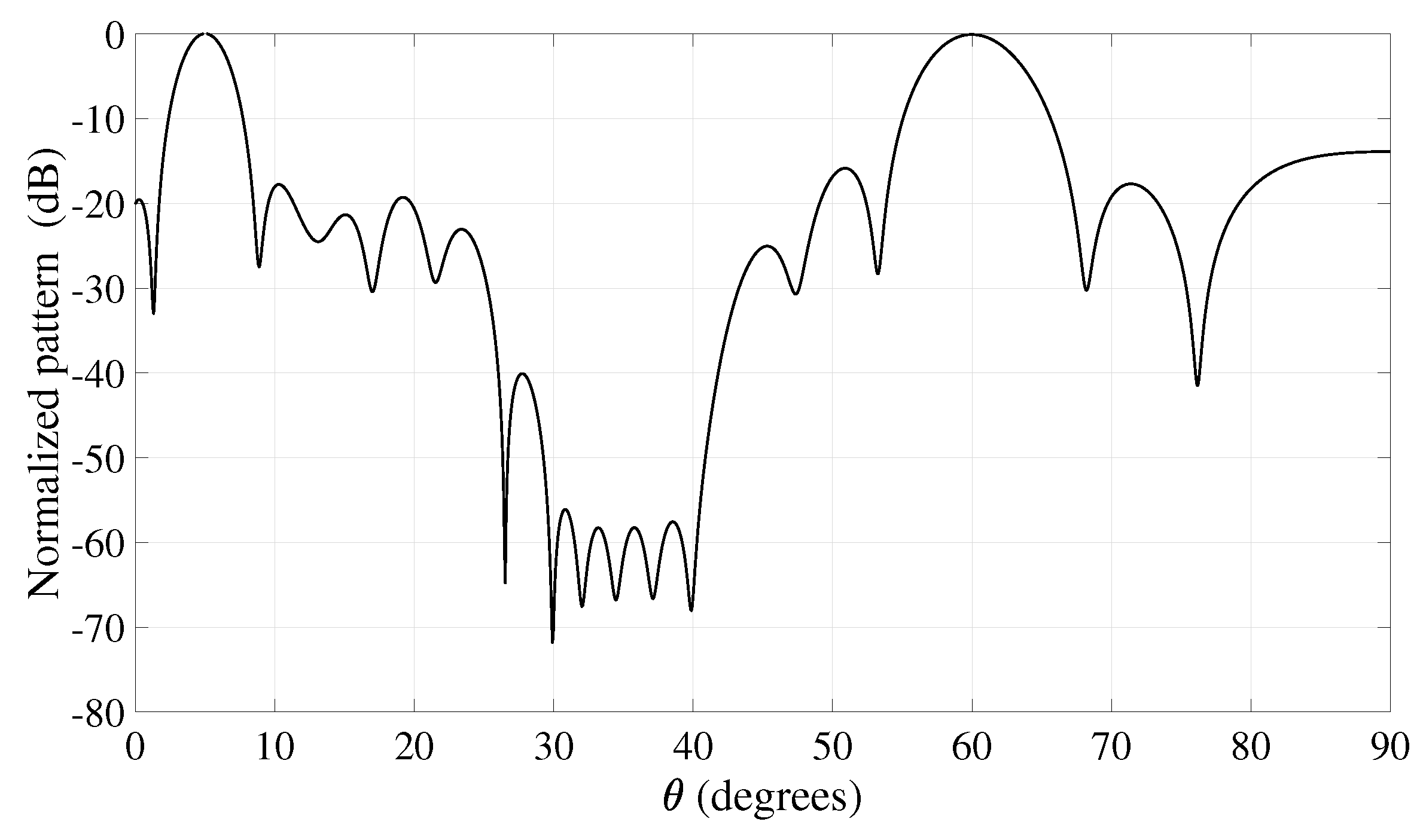
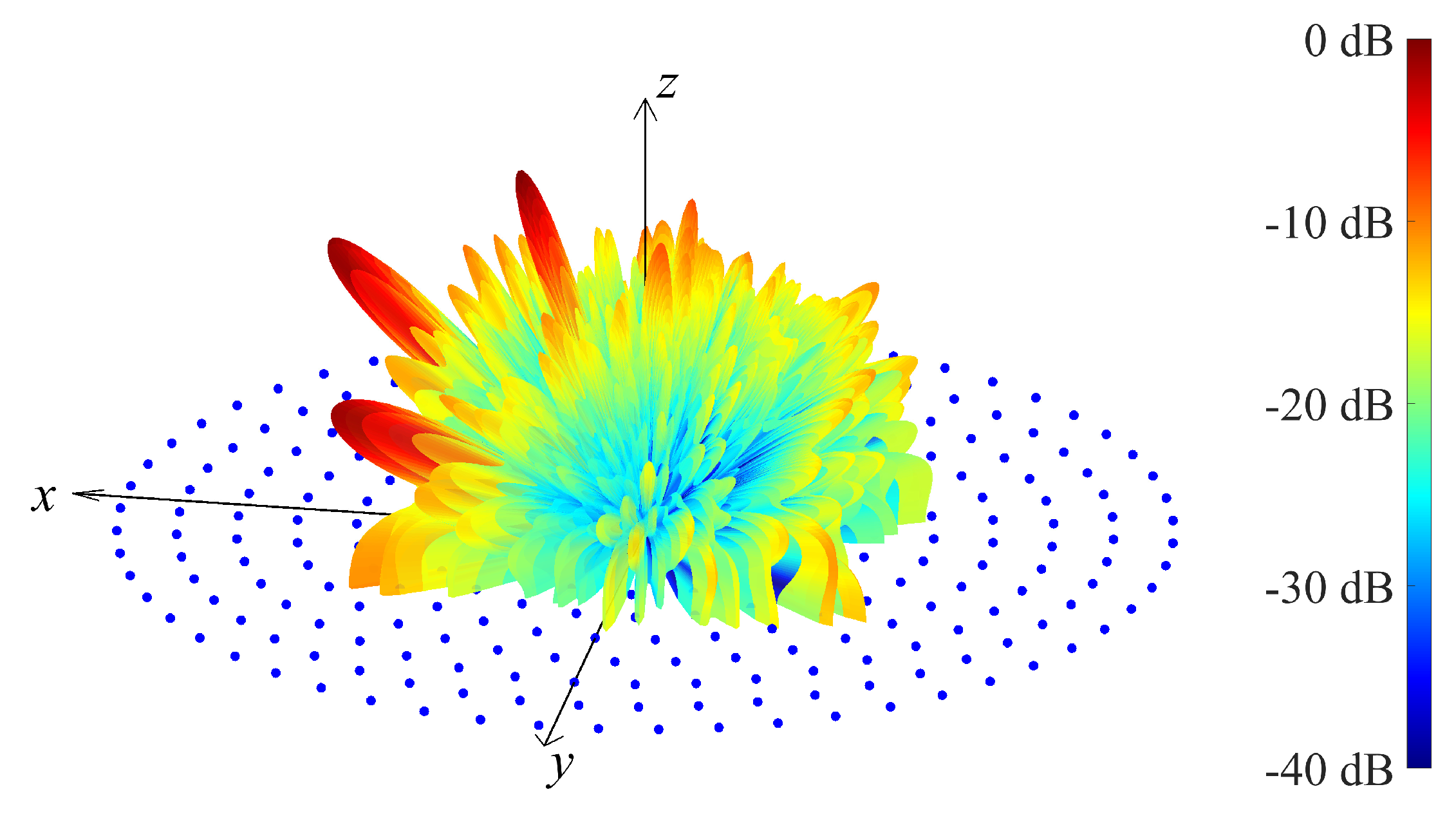
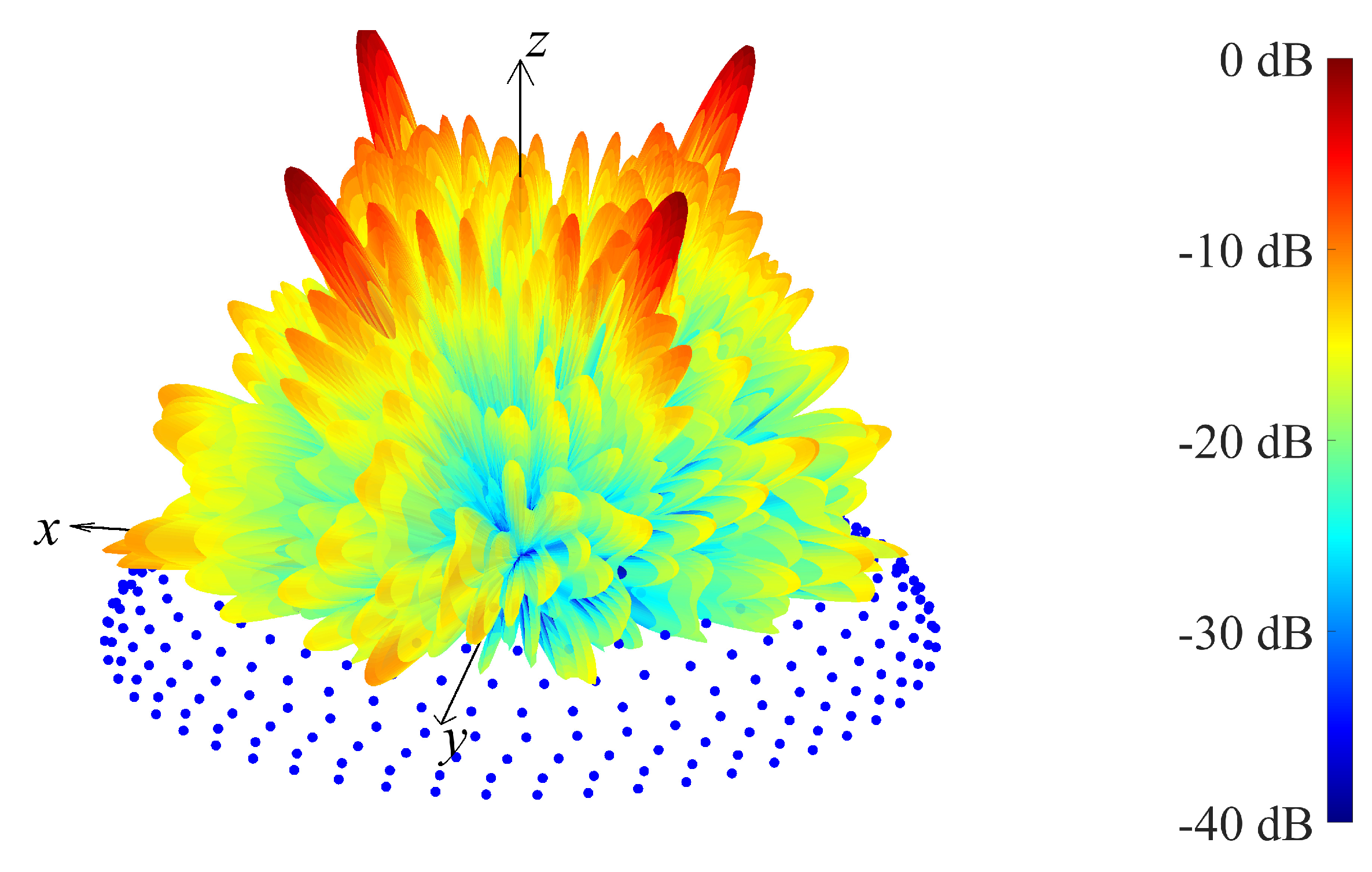
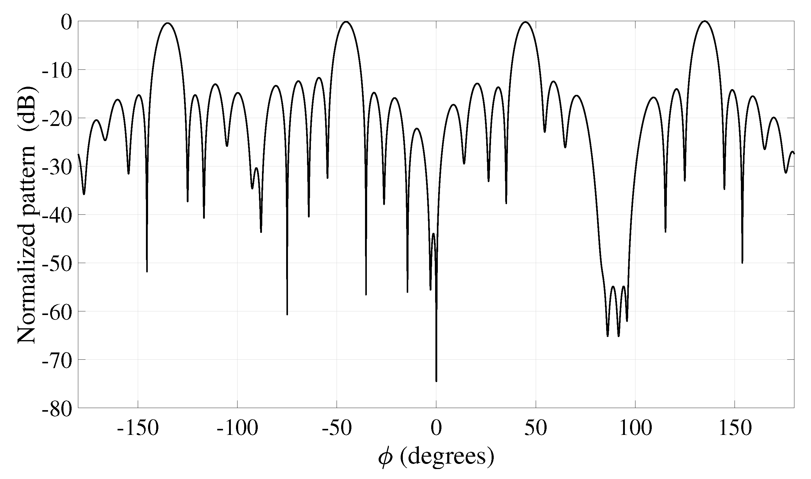
The fourth example refers to an array suitable for a compact 5G BS having a conformal geometry. The array consists of elements placed on rings, with their centers on the z axis, parallel to the plane and lying on the surface of a sphere having the center at the origin of the Cartesian system. More precisely, the radii and the heights of the rings are mm, mm; mm, mm; mm, mm; mm, mm; mm, mm; mm, mm; mm, mm; mm, mm; and , mm, while the corresponding number of elements are , , , , , , , , and . These values have been chosen to guarantee a minimum inter-element distance not lower than . Using this radiating structure, the last example is developed by considering a desired pattern with four main beams () directed at , , and , together with a notch at and a wide null region, obtained by imposing the notches at for , resulting in overall nulls. The 3D pattern derived by choosing the weights , , , and is plotted in Figure 8, while the corresponding 2D cut at is reported in Figure 9. These two figures confirm the ability of the algorithm to guarantee the generation of a four-beam pattern with a maximum SLL lower than −10 dB. A very deep notch is achieved at , and a satisfactory level is guaranteed in the wide null region, where the pattern lies below −50 dB. Finally, also in this example involving a conformal structure, the CPU time remained acceptable since approximately 74 s were sufficient to complete the 3D synthesis procedure.
Observations and Suggestions
One of the most interesting features of the presented algorithm is the availability of the weights , which provide significant versatility in satisfying the requirements of a specific problem. To this aim, some practical rules may be followed during the selection of the weights. In particular, their setting can be carried out following their order in the cost function by firstly specifying to impose the P maxima, then to equalize these maxima and to impose the nulls, and finally, to obtain an acceptable SLL. Some further refinements on some weights can be applied to match the problem requirements. In the proposed examples, just two of these further refinements were necessary to derive the provided results. Thus, in summary, a few preliminary executions of the algorithm can be considered sufficient to accomplish the synthesis. Regarding the magnitude of the weights, one may notice that for all examples, the weight referred to the nulls is usually much higher than the other ones. This characteristic is reasonable since the pattern value in a null is very low. Thus, in the cost function, this value must be properly amplified to be properly taken into account during the numerical evolution of the procedure.
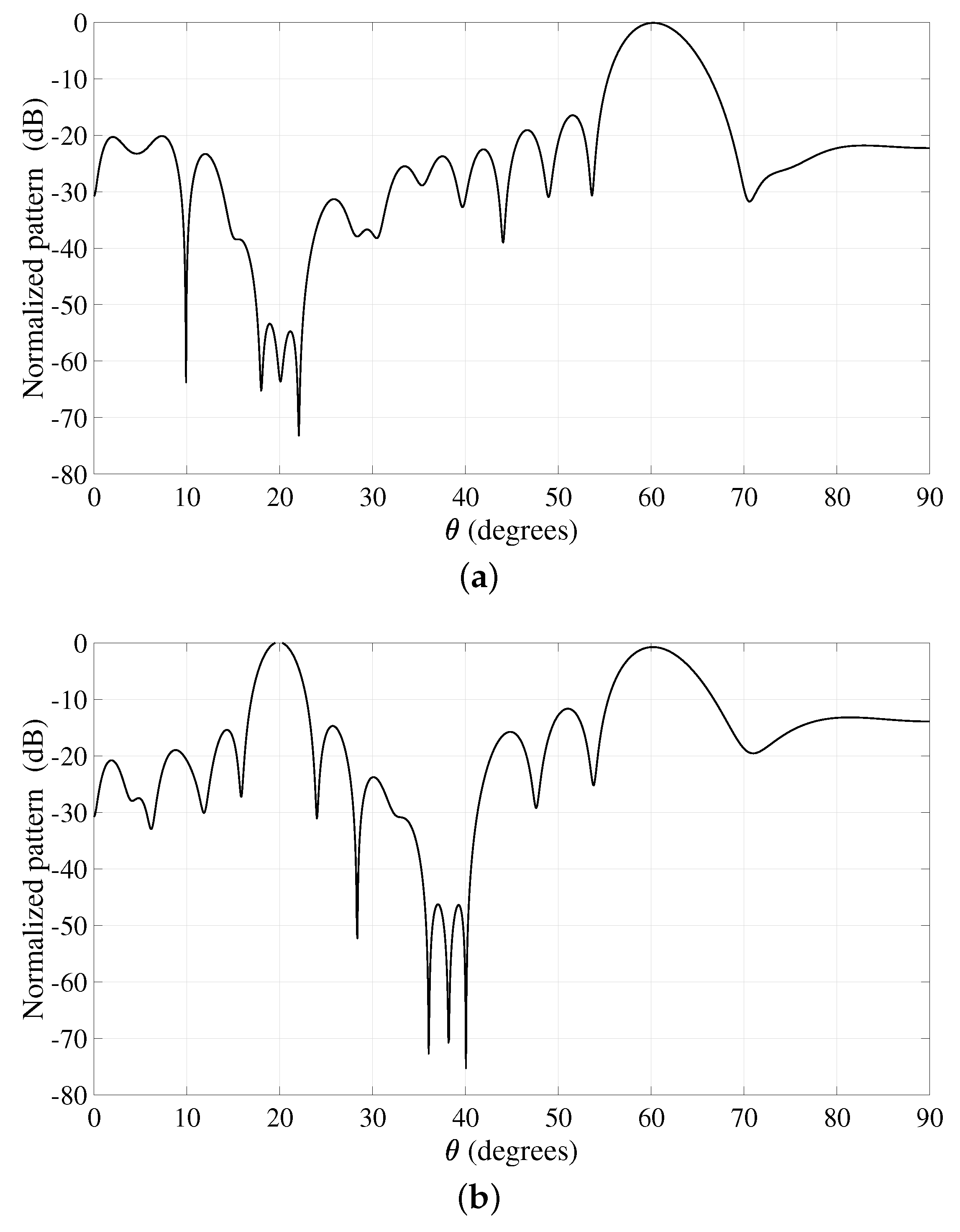
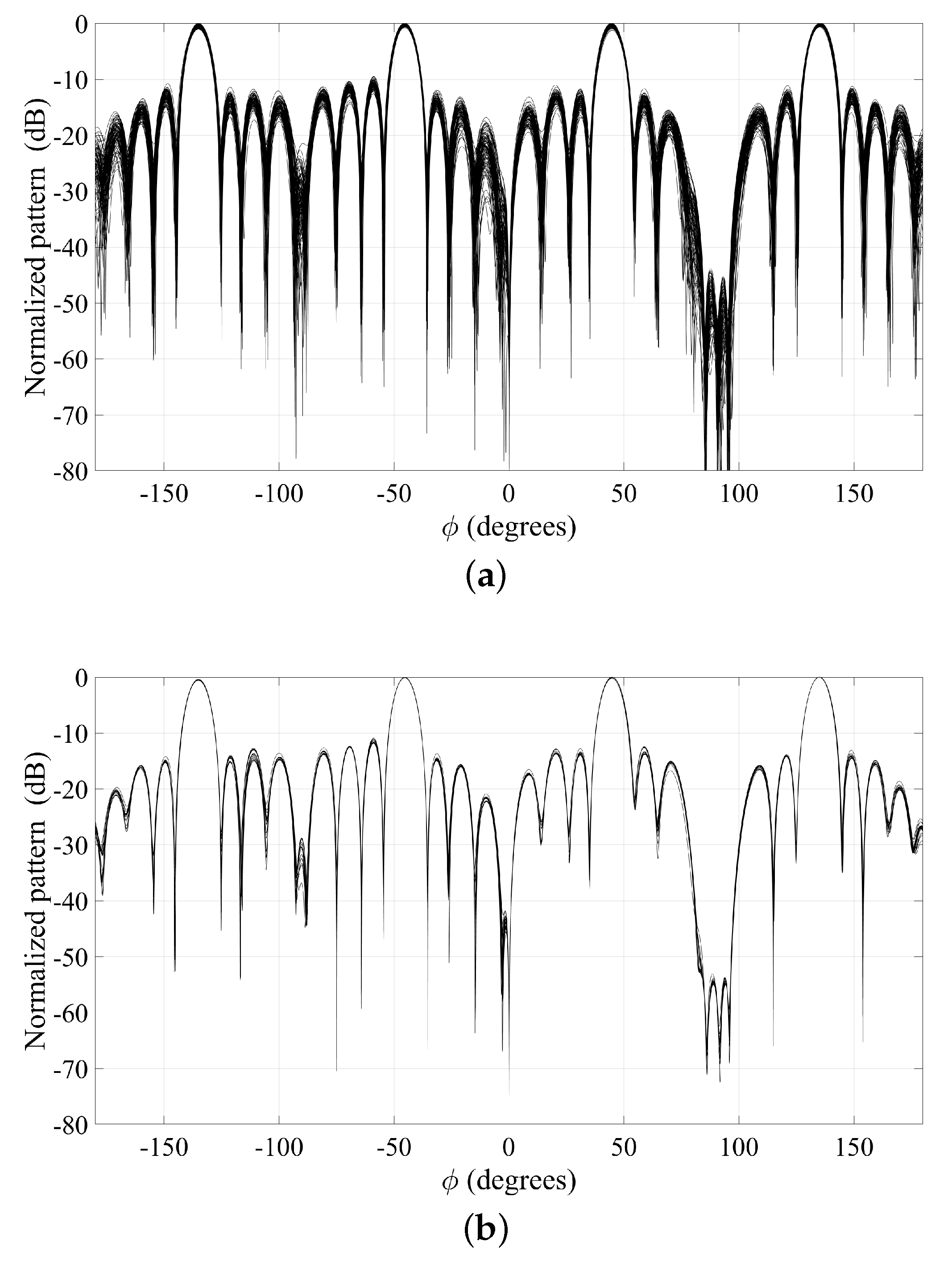
A final aspect that is worth discussing concerns the sensitivity of the achieved solution to the starting point. The provided numerical examples have shown that very good results can be obtained by adopting a very simple choice of the starting point for the phase vector. Precisely, in all of the proposed examples, a null vector of phases has been chosen. However, in order to investigate the dependency of the results on the initialization of the phase coefficients, different starting points may be used. To investigate this aspect, randomly selected sets of phases have been considered for each of the four examples. Figure 10a,b report, for the fourth example, the corresponding one hundred synthesized 2D pattern cuts at for and , respectively. A direct comparison of these figures with Figure 9 reveals that, with a sufficient number of iterations, the algorithm converges towards the same solution, thus revealing poor sensitivity to the starting point. A similar behavior has been observed for the other three examples.
5. Conclusions
An iterative algorithm for the 3D phase-only pattern synthesis of conformal antenna arrays in the presence of null and multibeam constraints has been presented. The method has been shown to be characterized by acceptable CPU times, thanks to the analytical expressions derived from the minimization of a weighted cost function that allow one to estimate the phase of each element in closed form at each iteration. The results have shown that the developed algorithm can be satisfactorily applied to arrays with arbitrary geometry and to synthesis problems characterized by different numbers of main lobes and wide nulls. Furthermore, the radiating structures adopted to test its performance have proven the suitability of the conceived solution for both 5G BSs and user equipments.
Author Contributions
M.C.: conceptualization and original draft preparation; G.P.: software and validation; F.B. and F.V.: review and editing; G.B.: conceptualization and software. All the authors have read and approved the final manuscript.
Funding
This research was partly funded by the Italian Ministry of University and Research (MIUR) within the project FRA 2018 (University of Trieste, Italy), entitled “UBER-5G: Cubesat 5G networks - Access layer analysis and antenna system development”.
Conflicts of Interest
The authors declare no conflict of interest. The funders had no role in the design of the study; in the collection, analyses, or interpretation of data; in the writing of the manuscript, or in the decision to publish the results.
References
- Haupt, R.L.; Rahmat-Samii, Y. Antenna array developments: A perspective on the past, present and future. IEEE Antennas Propag. Mag. 2015, 57, 86–96. [Google Scholar] [CrossRef]
- Liu, M.; Ma, L.; Wang, N.; Zhang, Y.; Yang, Y.; Wang, H. Passive multiple target indoor localization based on joint interference cancellation in an RFID system. Electronics 2019, 8, 426. [Google Scholar] [CrossRef]
- Hunter, A.M.; Andrews, J.G.; Weber, S. Transmission capacity of ad hoc networks with spatial diversity. IEEE Trans. Wirel. Commun. 2008, 7, 5058–5071. [Google Scholar] [CrossRef] [Green Version]
- Hu, W.; Wen, G.; Inserra, D.; Huang, Y.; Li, J.; Chen, Z. A circularly polarized antenna array with gain enhancement for long-range UHF RFID systems. Electronics 2019, 8, 400. [Google Scholar] [CrossRef]
- Comisso, M.; Buttazzoni, G.; Vescovo, R. Reconfigurable antenna arrays with multiple requirements: A versatile 3D approach. Int. J. Antennas Propag. 2017, 2017, 1–9. [Google Scholar] [CrossRef]
- Godara, L.C. Application of antenna arrays to mobile communications, Part II: Beam forming and direction-of-arrival considerations. Proc. IEEE 1997, 85, 1193–1245. [Google Scholar]
- Zhang, J.; Zhang, S.; Lin, X.; Fan, Y.; Pedersen, G.F. 3D radiation pattern reconfigurable phased array for transmission angle sensing in 5G mobile communication. Sensors 2018, 18, 4204. [Google Scholar] [CrossRef]
- Babich, F.; Comisso, M. Including the angular domain in the analysis of finite multi-packet peer-to-peer networks with uniformly distributed sources. IEEE Trans. Commun. 2016, 64, 2494–2510. [Google Scholar] [CrossRef]
- Pinchera, D.; Migliore, M.D.; Schettino, F.; Panariello, G. Antenna arrays for line-of-sight massive MIMO: Half wavelength is not enough. Electronics 2017, 6, 57. [Google Scholar] [CrossRef]
- Parchin, N.O.; Alibakhshikenari, M.; Basherlou, H.J.; Abd-Alhameed, R.A.; Rodriguez, J.; Limiti, E. MM-wave phased array quasi-Yagi antenna for the upcoming 5G cellular communications. Appl. Sci. 2019, 9, 978. [Google Scholar] [CrossRef]
- Kummer, W.H. Basic array theory. Proc. IEEE 1992, 80, 127–140. [Google Scholar] [CrossRef]
- Fuchs, B.; Fuchs, J.J. Optimal polarization synthesis of arbitrary arrays with focused power pattern. IEEE Trans. Antennas Propag. 2011, 59, 4512–4519. [Google Scholar] [CrossRef]
- Choni, Y.I. Synthesis of an antenna according to a given amplitude radiation pattern. AIEE Radio Eng. Electron. Phys. 1971, 16, 770–778. [Google Scholar]
- Mautz, J.R.; Harrington, R.F. Computational methods for antenna pattern synthesis. IEEE Trans. Antennas Propag. 1975, 23, 507–512. [Google Scholar] [CrossRef]
- Rodríguez, J.A.; Landesa, L.; Rodíguez, J.L.; Obelleiro, F.; Ares, F.; García-Pino, A. Pattern synthesis of array antennas with arbitrary elements by simulated annealing and adaptive array theory. Microw. Opt. Tech. Lett. 1999, 20, 48–50. [Google Scholar] [CrossRef]
- Akdeniz, M.R.; Liu, Y.; Samimi, M.K.; Sun, S.; Rangan, S.; Rappaport, T.S.; Erkip, E. Millimeter wave channel modeling and cellular capacity evaluation. IEEE J. Sel. Areas Commun. 2014, 32, 1164–1179. [Google Scholar] [CrossRef]
- Vaskelainen, L.I. Constrained least-squares optimization in conformal array antenna synthesis. IEEE Trans. Antennas Propag. 2007, 55, 859–867. [Google Scholar] [CrossRef]
- Han, Y.; Wan, C. Scalable alternating projection and proximal splitting for array pattern synthesis. Int. J. Antennas Propag. 2015, 2015, 1–13. [Google Scholar] [CrossRef]
- Mao, C.; Gao, S.; Wang, Y. Broadband high-gain beam-scanning antenna array for millimeter-wave applications. IEEE Trans. Antennas Propag. 2017, 65, 4864–48687. [Google Scholar] [CrossRef]
- Gao, X.; Dai, L.; Han, S.; Chih-Lin, I.; Heath, R.W., Jr. Energy-efficient hybrid analog and digital precoding for mmWave MIMO systems with large antenna arrays. IEEE J. Sel. Areas Commun. 2016, 34, 998–1009. [Google Scholar] [CrossRef]
- Khzmalyan, A.D.; Kondrat’yev, A.S. Fast iterative methods for phase-only synthesis of antenna array pattern nulls. Electron. Lett. 1995, 31, 601–602. [Google Scholar] [CrossRef]
- van Luyen, T.; Giang, T.V.B. Interference suppression of ULA antennas by phase-only control using bat algorithm. IEEE Antennas Wirel. Propag. Lett. 2017, 16, 3038–3042. [Google Scholar] [CrossRef]
- Buttazzoni, G.; Comisso, M.; Ruzzier, F.; Vescovo, R. Phase-only antenna array reconfigurability with Gaussian-shaped nulls for 5G applications. Int. J. Antennas Propag. 2019, 2019, 1–8. [Google Scholar] [CrossRef]
- Mouhamadou, M.; Vaudon, P.; Rammal, M. Smart antenna array patterns synthesis: Null steering and multi-user beamforming by phase control. Progr. Electromag. Res. PIER 2006, 60, 95–106. [Google Scholar] [CrossRef]
- Ghayoula, R.; Fadlallah, N.; Gharsallah, A.; Rammal, M. Phase-only adaptive nulling with neural networks for antenna array synthesis. IET Microw. Antennas Propag. 2007, 3, 154–163. [Google Scholar] [CrossRef]
- Comisso, M.; Vescovo, R. Multi-beam synthesis with null constraints by phase control for antenna arrays of arbitrary geometry. Electron. Lett. 2007, 43, 374–375. [Google Scholar] [CrossRef]
- Yu, B.; Yang, K.; Sim, C.; Yang, G. A novel 28 GHz beam steering array for 5G mobile device with metallic casing application. IEEE Trans. Antennas Propag. 2018, 66, 462–466. [Google Scholar] [CrossRef]
- Oliveri, G.; Gottardi, G.; Robol, F.; Polo, A.; Poli, L.; Salucci, M.; Chuan, M.; Massagrande, C.; Vinetti, P.; Mattivi, M.; et al. Co-design of unconventional array architectures and antenna elements for 5G base station. IEEE Trans. Antennas Propag. 2017, 65, 6752–6767. [Google Scholar] [CrossRef]
- Ismail, T.H.; Mismar, M.J.; Dawoud, M.M. Linear array pattern synthesis for wide band sector nulling. Progr. Electromag. Res. PIER 1999, 21, 91–101. [Google Scholar] [CrossRef]
- Güney, K.; Akdağli, A. Null steering of linear antenna arrays using a modified tabu search algorithm. Progr. Electromag. Res. PIER 2001, 33, 167–182. [Google Scholar]
- Andrews, J.G.; Buzzi, S.; Choi, W.; Hanly, S.V.; Lozano, A.; Soong, A.C.K.; Zhang, J.C. What will 5G be? IEEE J. Sel. Areas Commun. 2014, 32, 1065–1082. [Google Scholar] [CrossRef]
Figure 1.
Proposed algorithm.

Figure 2.
First example: 3D pattern.

Figure 3.
First example: 2D pattern cut at .

Figure 4.
Second example: 3D pattern.

Figure 5.
Second example: 2D pattern cut at .

Figure 6.
Third example: 3D pattern.

Figure 7.
Third example: 2D pattern cuts at (a) and (b) .

Figure 8.
Fourth example: 3D pattern.

Figure 9.
Fourth example: 2D pattern cut at .

Figure 10.
Fourth example: overlapping of one hundred 2D pattern cuts at obtained by randomly selected starting points for (a) and (b) .
Figure 10.
Fourth example: overlapping of one hundred 2D pattern cuts at obtained by randomly selected starting points for (a) and (b) .

© 2019 by the authors. Licensee MDPI, Basel, Switzerland. This article is an open access article distributed under the terms and conditions of the Creative Commons Attribution (CC BY) license (http://creativecommons.org/licenses/by/4.0/).
Share and Cite
MDPI and ACS Style
Comisso, M.; Palese, G.; Babich, F.; Vatta, F.; Buttazzoni, G. 3D Multi-Beam and Null Synthesis by Phase-Only Control for 5G Antenna Arrays. Electronics 2019, 8, 656. https://doi.org/10.3390/electronics8060656
AMA Style
Comisso M, Palese G, Babich F, Vatta F, Buttazzoni G. 3D Multi-Beam and Null Synthesis by Phase-Only Control for 5G Antenna Arrays. Electronics. 2019; 8(6):656. https://doi.org/10.3390/electronics8060656
Chicago/Turabian StyleComisso, Massimiliano, Gabriele Palese, Fulvio Babich, Francesca Vatta, and Giulia Buttazzoni. 2019. "3D Multi-Beam and Null Synthesis by Phase-Only Control for 5G Antenna Arrays" Electronics 8, no. 6: 656. https://doi.org/10.3390/electronics8060656
Note that from the first issue of 2016, this journal uses article numbers instead of page numbers. See further details here.