Multi-User Linear Equalizer and Precoder Scheme for Hybrid Sub-Connected Wideband Systems


Instituto de Telecomunicações and DETI, University of Aveiro, 3810-193 Aveiro, Portugal
*
Author to whom correspondence should be addressed.
Electronics 2019, 8(4), 436; https://doi.org/10.3390/electronics8040436
Submission received: 14 March 2019
/
Revised: 9 April 2019
/
Accepted: 11 April 2019
/
Published: 16 April 2019
(This article belongs to the Special Issue Millimeter-Wave (mmWave) Communications)
Abstract
:Millimeter waves and massive multiple-input multiple output (MIMO) are two promising key technologies to achieve the high demands of data rate for the future mobile communication generation. Due to hardware limitations, these systems employ hybrid analog–digital architectures. Nonetheless, most of the works developed for hybrid architectures focus on narrowband channels, and it is expected that millimeter waves be wideband. Moreover, it is more feasible to have a sub-connected architecture than a fully connected one, due to the hardware constraints. Therefore, the aim of this paper is to design a sub-connected hybrid analog–digital multi-user linear equalizer combined with an analog precoder to efficiently remove the multi-user interference. We consider low complexity user terminals employing pure analog precoders, computed with the knowledge of a quantized version of the average angles of departure of each cluster. At the base station, the hybrid multi-user linear equalizer is optimized by using the bit-error-rate (BER) as a metric over all the subcarriers. The analog domain hardware constraints, together with the assumption of a flat analog equalizer over the subcarriers, considerably increase the complexity of the corresponding optimization problem. To simplify the problem at hand, the merit function is first upper bounded, and by leveraging the specific properties of the resulting problem, we show that the analog equalizer may be computed iteratively over the radio frequency (RF) chains by assigning the users in an interleaved fashion to the RF chains. The proposed hybrid sub-connected scheme is compared with a fully connected counterpart.
1. Introduction
Mobile data traffic has increased over the years and the next generation (5G) is a response to this demand for higher data rates [1,2]. It is expected that 5G will achieve a minimum data rate of 1 Gb/s, 5 Gb/s for high mobility users, and 50 Gb/s for pedestrian users [3,4]. The frequency spectrum used by the mobile communications is currently saturated, so it is necessary to find another spectrum band for mobile applications. In this context the millimeter wave (mmW) band, with its huge available bandwidth [5], with wavelengths from 1 to 10 millimeters [6], can be an interesting solution. Other key technology for future generation communications is massive multiple-input-multiple-output (mMIMO), allowing achievement of higher data rates and better energy efficiency (EE) when compared to the previous generation, 4G-Long Term Evolution (LTE) [7].
The combination of mmW with mMIMO systems enables the use of a large antenna array at the base station (BS) and user terminals (UT) [8]. Massive MIMO, also known as large-scale antenna systems (LSAS), beyond improving EE, can also improve the spectrum efficiency (SE) of the mobile communications systems [9]. SE is independent of the number of antennas employed at the BS and grows with the increase of the number of radio frequency (RF) chains, as discussed in [10]. It is well known that when we have a large number of antennas, it is not feasible to have one dedicated RF chain per antenna, and consequently, a full digital beamforming (BF) architecture is not realistic due to the higher costs and power consumption [9,11]. On the other hand, a system that works only in the analog domain, by employing full analog BF, is not feasible due to the availability of only quantized phase shifters and the constraints on the amplitudes of these analog phase shifters. As a result, the fully analog architecture is normally limited to a single-stream transmission [12]. One possible solution to overcome these limitations is to consider hybrid digital and analog BF where the signal is processed at both analog and digital levels. When this hybrid architecture is compared with the fully digital one, the performance of the hybrid solution is limited by the number of RF chains, but it is possible to design efficient signal processing schemes to achieve a performance close to the fully digital counterpart [13].
1.1. Previous Work on Fully Connected Architectures
Some fully connected hybrid beamforming architectures for narrowband single-user systems were discussed in [14,15,16]. The work presented in [14] considered a transmit precoding and a receiver combining scheme for mmW mMIMO. In this work the spatial structure of the mmW channels was exploited to design the precoding/combining schemes as a sparse reconstruction problem. In [15] an iterative turbo-like algorithm was proposed that found the near-optimal pair of analog precoder/combiner. A matrix decomposition method that could convert any existing precoder/combining design for the full digital scheme into an analog–digital precoder/combining for the hybrid architecture was addressed in [16]. Approaches for narrowband multi-user systems were also considered in [17,18,19,20,21,22]. A limited feedback hybrid analog–digital precoding/combining scheme for multi-user systems was addressed in [17]. A heuristic hybrid BF was addressed in [18], where the proposed design could achieve a performance close to the fully digital BF with low-resolution phase shifters. A hybrid analog–digital precoding/combining multi-user system based on the mean-squared error (MSE) was proposed in [19]. The authors of [20] designed an iterative hybrid analog–digital equalizer that efficiently removed the multi-user interferences. In [21], an iterative precoder and combiner design was proposed by exploiting the duality of the uplink and downlink multi-user MIMO channels. In [22], a hybrid beamforming system based on a dual polarized array antenna was proposed for single user systems. The hybrid architecture for either single or multi-user the mmW mMIMO wideband systems was considered in [23,24,25]. Precoding solutions with codebook design for limited feedback spatial multiplexing in single user wideband mmW were developed in [23]. For the multi-user case, statistical MIMO orthogonal frequency division multiplexing (OFDM) beamformers without instantaneous channel information were designed in [24], where the beams were formed using the dominant eigenvectors to select the main directions. In [25], a downlink MIMO–OFDM hybrid multi-user precoder based on the vector quantization concept was proposed, where the total transmit power was minimized.
1.2. Previous Work on Sub-Connected Architectures
The previous works mainly focused on fully connected architectures. However, sub-connected architectures, where each RF chain is only connected to a subset of the available antennas, is more suited for practical applications due to its lower complexity. Narrowband fixed sub-connected hybrid architectures for single user systems were addressed in [26,27]. The authors of [26] proposed a two-layer optimization method jointly exploiting the interference alignment and fractional programming principles. First, the analog precoder and combiner were optimized via the alternating-direction optimization method and then the precoder and combiner were optimized based on an effective MIMO channel coefficient. In [27] two analog precoder schemes for high and low signal-to-noise ratio (SNR) condition were developed. For multi-user sub-connected narrowband architecture, some approaches were also proposed in [28,29,30,31,32]. In [28], the total achievable rate optimization problem with nonconvex constraints was decomposed into a series of sub-rate optimization problems for each sub-antenna array, and then a successive interference cancelation (SIC) based hybrid precoder was proposed. A low-complexity hybrid precoding and combining design was discussed in [29], where a virtual path was performed to maximize the channel gain and then, based on the effective channel, a zero-forcing precoding was applied to manage the interference. The scheme proposed in [30] efficiently controlled the multi-user interference by sequentially computing the analog part of the equalizer over the RF chains, using a dictionary obtained from the array response vectors. In [31], the Gram–Schmidt (GS) based antenna selection (AS) algorithm was used to obtain an appropriate antenna subset for the overlapped, interlaced, and dynamic architectures. Solutions for wideband sub-connected hybrid architectures were also considered in [32,33]. In [32], solutions for fully connected, fixed, and dynamic subconnected OFDM single user hybrid precoding were designed to maximize the sum rate. Precoding techniques for multi-user downlink massive mmWave MIMO–OFDM systems were proposed in [33]. A unified heuristic design for both fully connected and sub-connected hybrid structures was developed by maximizing the overall spectral efficiency.
1.3. Main Contributions
The previous works considered mainly a sub-connected hybrid architecture for single and multi-user narrowband systems. The works for wideband sub-connected hybrid architectures are very scarce in the literature and they mainly focus on solutions for the downlink considering OFDM modulations. To the best of our knowledge, sub-connected hybrid approaches for uplink of multi-user wideband mmWave massive MIMO systems have yet to be addressed in the literature. Therefore, in this paper we aim to fill this gap and design an efficient hybrid multi-user equalizer combined with a pure analog precoder for sub-connected uplink mmW massive MIMO single-carrier frequency division multiple access (SC–FDMA) systems. We consider single RF UTs employing a low complexity, yet efficient, analog precoder approach based on the knowledge of partial channel state information (CSI), i.e., only a quantized version of the average angle of departure (AoD) of each cluster is considered. The hybrid multi-user linear equalizer employed at the BS is optimized by using the bit-error-rate (BER) as a metric over all the subcarriers. We assume that the digital part of the equalizer is computed on a per subcarrier basis while the analog part is constant over the subcarriers. The analog domain hardware constraints considerably increase the complexity of the corresponding optimization problem. To simplify it, the merit function is first upper bounded, and by leveraging the specific properties of the resulting problem, we show that the analog equalizer may be computed iteratively over the RF chains by assigning the users in an interleaved fashion to the RF chains, using a dictionary built from the array response vectors. The results show that the performance penalty of the sub-connected multi-user equalizer approach to the fully connected counterpart decreases as the number of RF chains increases.
1.4. Organization and Notation
This paper is organized as follows: Section 2 describes the transmitter, channel, and receiver system model. In Section 3 the analog precoder employed at each UT is described, while in Section 4 the sub-connected hybrid analog–digital multi-user equalizer is derived. In Section 5, the main performance results are presented. Finally, the conclusions are discussed in Section 6.
The following notation is used in this paper: boldface uppercase letters, boldface lowercase letters, and italic letters denote matrices, vectors and scalars, respectively. The operations , , , and represent the transpose, the Hermitian, the conjugate, and the trace of a matrix, respectively. The operator corresponds to the diagonal entries of the matrix . The identity matrix of size is denoted . and represent the expectation operator and an length sequence, respectively. denotes the absolute value of a. represents the entry of the nth row and lth column of the matrix . The indices, t, , and represent the time domain, subcarrier in the frequency domain, and user terminal, respectively.
2. System Model
In this section, we describe the transmitter, the channel model, and the receiver for the considered uplink massive MIMO mmW SC–FDMA system.
2.1. Transmitter Description
We assume UTs sharing the same radio resources, each equipped with transmit antennas and with a single RF chain. Figure 1 presents the general schematic of the uth user terminal. Firstly, the time domain -length sequence , with , is divided into data blocks of size , where represents the rth data block. Then, this time domain sequence is moved to the frequency domain and the resulting sequence denominated by , where is the discrete Fourier transform (DFT) of the time domain sequence . After that, the frequency domain data is interleaved and mapped to the OFDM symbol. To simplify the formulation, we assume that , which means that only a single -length block is considered and assume the identity mapping. Therefore, the frequency domain sequence is the DFT of the full-time sequence . After the cyclic prefix (CP), an analog precoder is employed. Due to the hardware constraints, we only consider analog phase shifters that force all coefficients of the precoder to have equal magnitude, i.e., , and furthermore, it is assumed that they are constant over the subcarriers. Therefore, the discrete transmit complex baseband signal of the uth user at subcarrier k can be represented as
where . The design of the analog precoder coefficients will be presented in the next Section. We assume that the number of users is lower than the number of RF chains () at the receiver, .
2.2. Channel Model Description
We assume a channel given by the sum of the contribution of clusters; each one contributes with propagation paths. The considered delay-d MIMO channel matrix of the uth user can be written as
and the corresponding frequency domain channel matrix of the uth user at the kth subcarrier is given by
where represents the number of receive antennas, represents the path-loss between the transmitter and the receiver, is the complex path gain of the lth ray in the qth scattering cluster, and a raised-cosine filter is adopted for the pulse shaping function for -spaced signaling, as in [22]. The th cluster has a time delay , angles of departure , and arrival . Each ray from qth cluster has a relative time delay , relative angles of departure , and arrival . The paths delay is uniformly distributed in where D denotes the length of the CP, and the angles follow the random distribution mentioned in [22], such that . Finally, the vectors and represent the normalized receive and transmit array response vectors, respectively. For an N-element uniform linear array (ULA), the array response vector can be given by
where , is the wavelength, and is the inter-element spacing. The channel matrix of the uth user can also be expressed as
where is a diagonal matrix, with entry that corresponds to the path gain of the lth ray in the qth scattering cluster. and hold the transmit and receive array response vectors of the uth user, respectively.
2.3. Receiver Description
At the receiver we consider a hybrid analog–digital sub-connected architecture, where each RF chain is connected into a group of antennas, where is the number of RF chains, as represented in Figure 2. We assume that the number of RF chains is lower than the number of receive antennas, .
The frequency domain received signal at the kth subcarrier can be written as
where is the zero mean Gaussian noise with variance , and and represent the discrete transmit complex baseband signal and analog precoder of the uth user at subcarrier k, respectively. We consider a sub-connected hybrid analog–digital multi-user equalizer to efficiently separate the users, as shown in Figure 2. Initially, the signal is processed through the phase shifters modeled by the vector , where all elements of have equal magnitudes . The overall analog matrix that represents the connection between each subset of antennas and the corresponding chain, has a block diagonal structure
As in the analog precoder, we also assume that the analog part of the equalizer is constant for all subcarriers.
After that, the CP is removed on each RF chain and the signal is moved to the frequency domain by applying the DFT operator. Then, the samples of each subcarrier pass through the digital part of the equalizer modeled by matrix . Therefore, the resulting signal at the end of the analog and digital processing equalizer can be written as
where represents the overall equivalent channel between the U users and the receiver, and denotes the frequency domain transmitted signal of all users at the kth subcarrier.
Finally, the equalized signals are demapped and moved to the time domain by using the inverse DFT, obtaining the estimates of the uth user transmitted -length data block .
3. Analog Precoder Design
In this section, we design a low complexity analog precoder to be employed at the transmitters. These precoders are computed based on the knowledge of partial CSI, i.e., only a quantized version of the average AoD of each cluster is used. These angles estimated at the receiver are quantized as
and then sent to the transmitters. In this paper, for the sake of simplicity, we consider uniform quantizers, i.e., the uniform function has (n is the number of quantization bits) levels equally spaced between clipping levels and .
With the knowledge of these quantized angles, user u should start by computing the correlation matrix , where the overall matrix is given as
with computed from
To compute the analog precoders, we first need to apply the eigenvalue decomposition to the correlation matrix , i.e., , where is a diagonal matrix whose elements are the matrix eigenvalues and a square matrix where the ith column is the ith eigenvector of . Finally, entry of the proposed analog precoders of the uth user is set as
where denotes the argument of complex number and represents entry of the eigenvector corresponding to the largest eigenvalue of the correlation matrix . Hence, the beam follows the best channel direction, improving the transmit/receive link reliability.
4. Multi-User Equalizer Design
In this section, we design a hybrid analog–digital sub-connected equalizer for multi-user mmW mMIMO to be employed at the receiver side. A decoupled transmitter–receiver optimization problem is assumed in this paper, since a joint optimization problem is a very complex task. The overall analog matrix defined in (7) and the digital matrices are optimized by minimizing the BER, which is equivalent to minimize the MSE.
4.1. Problem Formulation
It can be shown that the digital part of the equalizer that minimizes the BER is given by
since it maximizes the overall signal-to-interference-plus-noise-ratio (SINR) of the uth user at time t, , i.e., the SINR relatively to data symbol [23].
Let us now describe the method to compute the analog part of the considered sub-connected architecture. By using the matrix inversion lemma [34], the overall analog–digital equalizer matrix simplifies to
Assuming quadrature phase shift keying (QPSK) constellations for simplicity and without loss of generality, the average BER can be written as
where represents the well-known Q-function and with the given by
where represents the entry of the uth row and column of the matrix . From (16) we see that is independent of the time index. So, we can simplify (15) as
with .
The optimization problem to compute the analog part of the equalizer may be mathematically formulated as
where denotes the feasible set for the analog equalizer.
4.2. Proposed Method Derivation
Due to the non-convex nature of the merit function and the constraint imposed in problem (18), it is difficult or even impossible to obtain an analytical solution to the optimization problem at hand. Moreover, as we are considering a multi-user scenario, the resulting average BER is a weighted function of the average BER for each user, making it even harder to obtain a solution to the aforementioned problem. Hence, instead of an exact solution to problem (18) we will derive, in the following, an algorithm to obtain an approximate solution to the previous optimization problem.
Using the exponential upper bound of the Q-function we obtain , and as a consequence we have
Replacing Equation (16) in Equation (19), and after some mathematical manipulations, we obtain,
and then an approximate solution to the optimization problem (18) may be obtained from the following simplified optimization problem
where represents the equivalent channel of user u. To solve it, we propose to iteratively compute matrix column by column, which in practice corresponds to iteratively adding RF chains to the receiver. Let matrix and vector denote the first columns and column of matrix , respectively; then we can define . The aim is to compute iteratively instead to compute the overall matrix at once, and thus the optimization problem can be modified as
From the definition of and the Gram–Schmidt orthogonalization follows [35], where , and . Note that is a block diagonal matrix and therefore and are also block diagonal. Therefore, the term in the denominator of the merit function of the optimization problem (22) can be simplified to
Notice that the first term in Equation (23) is constant at iteration , since it does not depend on vector , and is equal to zero for the first iteration. Furthermore, as is a projection matrix it follows that
with equality if . Therefore, if one of the terms of Equation (23) is large, the other one must be small and the following approximation follows,
Nonetheless, due to the independence of the user channels, if leads to a large value for the term for user , then with high probability for the other users , the value of this term will be small. For this reason, may be approximated as follows
Therefore, the optimization problem (22) can be approximated by
where is a constant and thus it only depends on the channels and matrix computed in the previous iteration. represents the column i of the elements of set .
Therefore, the optimization problem (22) may be simplified to
In spite of the previous simplifications, the optimization problem is still non-convex and hard to solve due to the constraint . Therefore, to further simplify it, we replace the set by the codebook , where is a block diagonal matrix where all blocks are zero except , which is equal to the identity matrix, i.e., the elements of the codebook are the normalized receiver array response vectors, which leads to the simpler optimization problem
Notice that we need to follow some criterion to associate a given user to iteration . We propose to do this association using the following mapping between users and iterations , i.e., the users are interleaved along the iterations. For example, for and , we have .
The procedure to obtain the analog part of the equalizer matrix is presented in Algorithm 1. It can be summarized as follows: Firstly we start with user 1, (line 1) and compute the projection matrix (line 4). After that, we compute the merit function of the optimization problem (29) for each element of the codebook (lines 5–9). Vector is set to be equal to the element of codebook with the lowest value (lines 10–11). Then, the column vector is added to matrix to form (line 12). With , the same procedure may be repeated for the other users according to the mapping between users and iterations defined by .
To compute the optimization problem of (29), we need to compute the correlation matrix for all the elements of the selected codebook , which may be accomplished with the following expression:
Notice that since is an idempotent matrix. Nonetheless, as the Gram–Schmidt procedure may lead to a loss of orthogonality among vectors [35], we use a Gram–Schmidt algorithm with reorthogonalization that amounts to applying two times the projection matrix or using instead of .
| Algorithm 1: The proposed analog–digital multi-user linear equalizer algorithm for sub-connected architecture |
| Inputs: |
| Analog Part of the equalizer |
| 1: |
| 2: for i = 1 to do |
| 3: |
| 4: |
| 5: |
| 6: for k = 1 to do |
| 7: |
| 8: |
| 9: end for |
| 10: |
| 11: |
| 12: |
| 13: |
| 14: end for |
| Digital part of the equalizer |
| return: , |
4.3. Complexity Analysis
The steps presented in Algorithm 1 describe the procedure to obtain the analog and digital parts of the proposed equalizer. In the following, the computational complexity of Algorithm 1 is analyzed. Matrix at line 4 may be computed with complexity, with , since matrix is block diagonal and each column has only non-zero elements. To obtain vector at line 7, the vector must be calculated. As both and are block diagonal with blocks of size and is a block diagonal matrix where all blocks are zero except , which is equal to the identity matrix, then the product requires complexity. As the resulting vector has only non-zero elements and is a matrix with dimension , may be computed with complexity. As the computation done in line 7 is repeated for all subcarriers and all RF chains, the overall complexity of lines 6–9 is . Line 10 requires the computation of the minimum of vector , whose complexity is . In line 11 we compute vector with complexity . The complexity of line 12 is identical to line 11. As the previous must be repeated for all RF chains, the overall complexity is times the individual complexities previously described. The computation of the digital equalizer must be performed for all subcarriers and requires the inversion of a matrix with size , resulting in a complexity . Therefore, the computational complexity of the proposed algorithm is linear in the number of subcarriers, quadratic with the number of antennas per RF chain, and cubic with the number RF chains. The full connected architecture would require a complexity scaling quadratically with the number of antennas and for the full-digital architecture the complexity is a cubic function of the number of antennas.
5. Performance Results
In this section, we evaluate the performance of the proposed multi-user linear equalizer and precoder scheme designed for hybrid sub-connected wideband mmW systems.
The carrier frequency was set to 72 GHz and for each user, the clustered wideband channel model was considered, as discussed in Section 2, with five clusters , all with the same average power, such that , and each one contributed with propagation path. The path delays were uniformly distributed in the CP interval. We considered a ULA with antenna element spacing set to half-wavelength, but it should be emphasized that the schemes proposed in this paper can be applied to any antenna arrays. The azimuth angles of departure and arrival had a Laplacian distribution as in [20] and were considered to have an angle spread of for both the transmitter and receiver. It was assumed a QPSK modulation, perfect synchronization, and that the CSI is known at the receiver side. At the transmitter, only a quantized version of the average angle of departure of each cluster was known. We assumed subcarriers, and the CP was set to be a quarter of the number of subcarriers, such that . We considered a Monte-Carlo simulation with a length of 100,000 SC–FDMA blocks. The average BER was considered the performance metric, presented as a function of , where is the average bit energy and is the one-sided noise power spectral density. We considered that the average was identical for all the users u and is given by .
We considered that each transmitter had a single RF chain and was equipped with antennas. At the receiver side, it was assumed that a sub-connected architecture existed, where each RF chain was connected to a group of antennas, with antennas. The results were compared with the fully connected counterpart that could be obtained from the proposed one by relaxing the optimization constraints, since each RF chain was connected to all antennas. The main simulation parameters are presented in Table 1.
Figure 3 depicts the results for the proposed hybrid sub-connected multi-user equalizer with the analog precoder for two, four, and eight users. In this figure, it was assumed perfect knowledge of the average AoD of each cluster. It was also assumed eight RF chains existed, which meant that each one was connected to two antennas. As it can be seen in Figure 3, the performance of both sub- and fully connected improved as the number of users decreased, as expected, since the multi-user equalizer had to deal with less interference and the available degrees of freedom could be used to provide more diversity. We could also observe a performance penalty of the sub-connected approach against the fully connected one of approximately 2 dB, independently of the number of users, at a target BER of . This was because the number of connections of the fully-connected architecture was larger than the number of connections for the sub-connected architecture and, as expected, the result for the fully-connected one was better than for the sub-connected architecture. The worst performance, for both fully and sub-connected approaches, was obtained for the full load case, i.e., when the number of users was equal to the number of RF chains .
In Figure 4 we present results for different numbers of RF chains and two users. If the number of antennas () connected to each RF chain was reduced, we verified that the penalty for fully digital approach decreased. We could observe a penalty of approximately 3 dB, 2 dB, and 0 dB for , , and , respectively (BER of ). This happened because more RF chains and consequently less antennas per chain increase the number of available degrees of freedom of the sub-connected architecture. For the extreme case of (one RF chain per antenna) the curve obtained for the sub-connected approximately overlapped the one obtained for the fully connected.
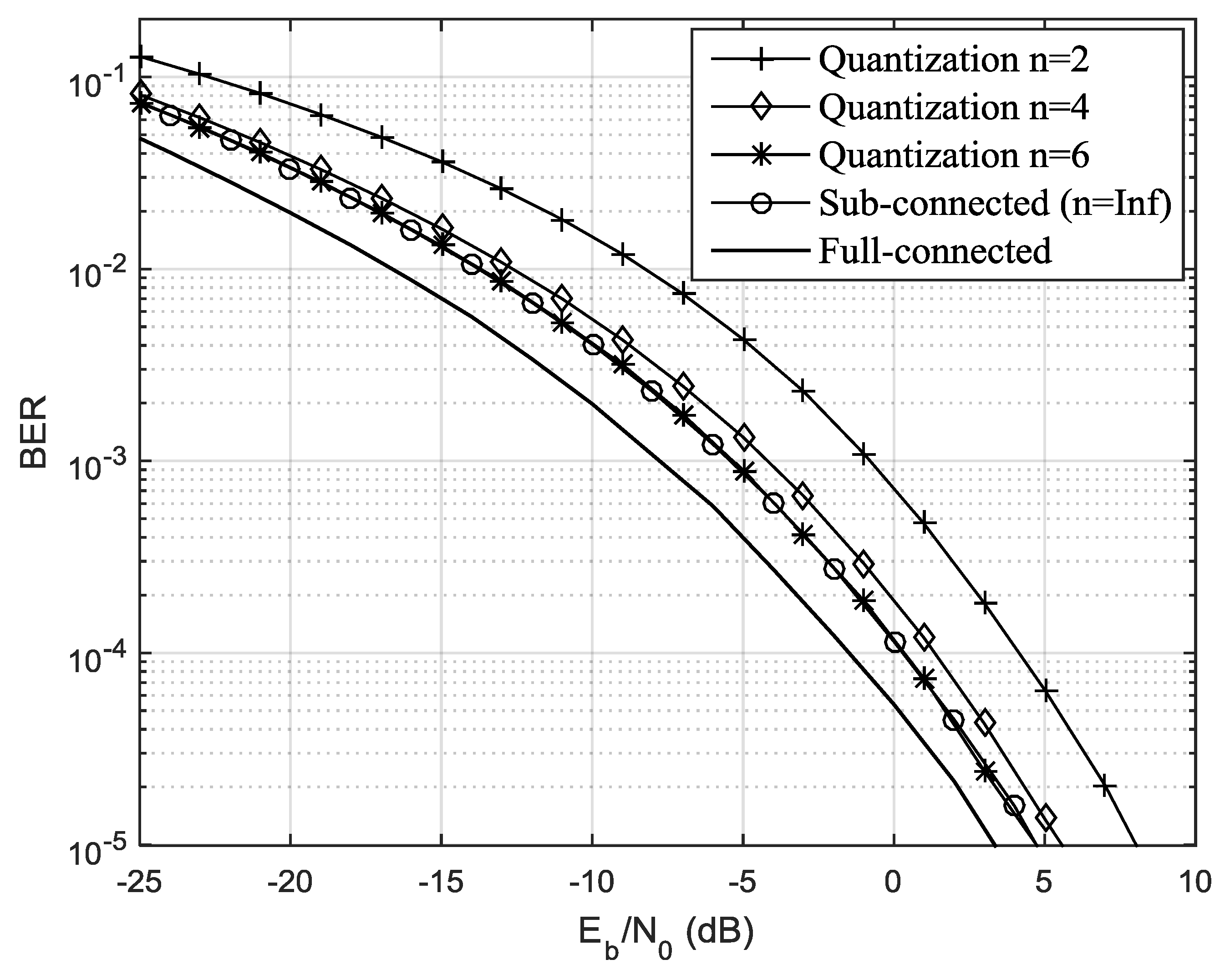
As seen in Figure 5 and Figure 6, we evaluated the impact of imperfect knowledge of the average AoD at the transmitter side. To compute the analog precoders we assumed the knowledge of only a quantized version of the average AoD of each cluster, as discussed in Section 3. We presented results for quantization bits. Figure 5 and Figure 6 depict the results for two and eight users, respectively. As expected, increasing the number of quantization bits improved the performance of the proposed sub-connected scheme and tended to the one achieved for perfect knowledge of the average AoD () for both cases . When the number of bits in the quantizer was lower, the performance was worse compared to the perfect curve. In Figure 5 we can observe a performance penalty, for BER of , of approximately 5 dB, 1.5 dB, and 0 dB, for n = 2, 4, and 6, respectively. This means that a very limited number of bits for the quantization of the average AoD of each cluster was enough to get a performance close to the perfect case. Since the mmW channels were usually sparse, the amount of information needed to be fed back from the BS to the UTs was small.
6. Conclusions
In this paper, we proposed an analog precoder combined with an efficient hybrid analog–digital multi-user equalizer for sub-connected mmW massive MIMO SC–FDMA systems. At the UT, we proposed a low complexity pure analog precoder that requires the knowledge of a quantized version of the average AoD of each cluster. At the BS, a hybrid analog–digital multi-user equalizer was developed for a sub-connected architecture. It was assumed that the analog part was constant over all subcarriers, while the digital part was computed on a per subcarrier basis. We considered a minimum MSE-based equalizer for the digital part, and the analog part was optimized using the average bit-error-rate of all subcarriers as metric. In order to simplify the optimization problem at hand, the merit function was first upper bounded and then, due to the specific properties of the resulting problem, we showed that the analog part of the hybrid equalizer may be computed iteratively over the RF chains by assigning the users in an interleaved fashion to the RF chains.
The numerical results show that the proposed wideband hybrid multi-user linear equalizer is quite efficient at removing the multi-user interference, and the performance tends to the one achieved by the fully connected counterpart as the number of RF chains increases. Furthermore, only a few bits are required for the quantization of the average AoD of each cluster to obtain a performance close to the perfect case. The small performance gap between the proposed sub-connected approach and the fully connected one, together with the lower complexity, make it a very interesting choice for practical systems.
Author Contributions
Conceptualization, D.C. and A.S.; software, S.T. and R.S.; validation, S.T. and R.S.; formal analysis, D.C.; investigation, S.T. and R.S.; writing—original draft preparation, D.C., A.S., and A.G.; writing—review and editing, D.C., A.S., and A.G.; funding acquisition, A.S.
Funding
This work is supported by the European Regional Development Fund (FEDER), through the Competitiveness and Internationalization Operational Program (COMPETE 2020) of the Portugal 2020 framework, Regional OP Centro (CENTRO 2020), Regional OP Lisboa (LISBOA 14-20), and by FCT/MEC through national funds, under Project MASSIVE5G (AAC nº 02/SAICT/2017), and in part by the European Structural and Investment Funds (FEEI) through the Competitiveness and Internationalization Operational Program—COMPETE 2020 and by the National Funds through the Foundation for Science and Technology under the Project RETIOT under Grant POCI-01-0145-FEDER-016432.
Conflicts of Interest
The authors declare no conflict of interest.
References
- Demestichas, P.; Georgakopoulos, A.; Karvounas, D.; Tsagkaris, K.; Stavroulaki, V.; Lu, J.; Xiong, C.; Yao, J. 5G on the Horizon: Key Challenges for the Radio-Access Network. IEEE Veh. Technol. Mag. 2013, 8, 47–53. [Google Scholar] [CrossRef]
- Hossain, E.; Rasti, M.; Tabassum, H.; Abdelnasser, A. Evolution toward 5G multi-tier cellular wireless networks: An interference management perspective. IEEE Wirel. Commun. 2014, 21, 118–127. [Google Scholar] [CrossRef]
- Roh, W.; Seol, J.; Park, J.; Lee, B.; Lee, J.; Kim, Y.; Cho, J.; Cheun, K.; Aryanfar, F. Millimeter-wave beamforming as an enabling technology for 5G cellular communications: Theoretical feasibility and prototype results. IEEE Commun. Mag. 2014, 52, 106–113. [Google Scholar] [CrossRef]
- Bogale, T.E.; Le, L.B. Massive MIMO and mmWave for 5G Wireless HetNet: Potential Benefits and Challenges. IEEE Veh. Technol. Mag. 2016, 11, 64–75. [Google Scholar] [CrossRef]
- Swindlehurts, A.; Ayanoglu, E.; Heydari, P.; Capolino, F. Millimeter-wave massive MIMO: The next wireless revolution? IEEE Commun. Mag. 2014, 52, 56–62. [Google Scholar] [CrossRef]
- Pi, Z.; Khan, F. An introduction to millimeter-wave mobile broadband systems. IEEE Commun. Mag. 2011, 49, 101–107. [Google Scholar] [CrossRef]
- Prasad, K.; Hossain, E.; Bhargava, V.K. Energy efficiency in massive MIMO-based 5G networks: Opportunities and challenges. IEEE Wirel. Commun. 2017, 24, 86–94. [Google Scholar] [CrossRef]
- Vu, T.K.; Liu, C.-F.; Bennis, M.; Debbah, M.; Latva-Aho, M.; Hong, C.S. Ultra-Reliable and Low Latency Communication in mmWave-Enabled Massive MIMO Networks. IEEE Commun. Lett. 2017, 21, 2041–2044. [Google Scholar] [CrossRef]
- Han, S.; Lin, C.; Rowell, C.; Xu, Z.; Wang, S.; Pan, Z. Large scale antenna system with hybrid digital and analog beamforming structure. In Proceedings of the 2014 ICC—2014 IEEE International Conference on Communication Workshop (ICC), Sydney, NSW, Australia, 10–14 June 2014; pp. 842–847. [Google Scholar]
- Tan, W.; Matthaiou, M.; Jin, S.; Li, X. Spectral Efficiency of DFT-Based Processing Hybrid Architectures in Massive MIMO. IEEE Wirel. Commun. Lett. 2017, 6, 586–589. [Google Scholar] [CrossRef]
- Roze, A.; Crussiere, M.; Helard, M.; Langlais, C. Comparison between a hybrid digital and analog beamforming system and a fully digital Massive MIMO system with adaptive beamsteering receivers in millimeter-Wave transmissions. In Proceedings of the 2016 International Symposium on Wireless Communication Systems (ISWCS), Poznan, Poland, 20–23 September 2016; pp. 86–91. [Google Scholar]
- Alkhateeb, A.; El Ayach, O.; Leus, G.; Heath, R.W. Channel Estimation and Hybrid Precoding for Millimeter Wave Cellular Systems. IEEE J. Sel. Top. Process. 2014, 8, 831–846. [Google Scholar] [CrossRef]
- Alkhateeb, A.; Mo, J.; González-Prelcic, N.; Heath, R., Jr. MIMO precoding and combining solutions for millimeter-wave systems. IEEE Commun. Mag. 2014, 52, 122–131. [Google Scholar] [CrossRef]
- Ayach, O.; Rajagopal, S.; Surra, S.; Pi, Z.; Heath, R. Spatially sparse precoding in millimeter wave MIMO systems. IEEE Trans. Wirel. Commun. 2014, 13, 1499–1513. [Google Scholar] [CrossRef]
- Gao, X.; Dai, L.; Yuen, C.; Wang, Z. Turbo-Like Beamforming Based on Tabu Search Algorithm for Millimeter-Wave Massive MIMO Systems. IEEE Trans. Veh. Technol. 2016, 65, 5731–5737. [Google Scholar] [CrossRef]
- Ni, W.; Dong, X.; Lu, W.S. Near-optimal hybrid processing for massive MIMO systems via matrix decomposition. IEEE Trans. Signal Process. 2017, 65, 3922–3933. [Google Scholar] [CrossRef]
- Alkhateeb, A.; Leus, G.; Heath, R.W. Limited feedback hybrid precoding formulti-user millimeter wave systems. IEEE Trans. Wirel. Commun. 2015, 14, 6481–6494. [Google Scholar] [CrossRef]
- Sohrabi, F.; Yu, W. Hybrid digital and analog beamforming design for large-scale antenna Arrays. IEEE J. Sel. Top. Signal Process. 2016, 10, 501–513. [Google Scholar] [CrossRef]
- Nguyen, D.H.N.; Le, L.B.; Le-Ngoc, T.; Heath, R.W. Hybrid MMSE Precoding and Combining Designs for mmWave Multiuser Systems. IEEE Access 2017, 5, 19167–19181. [Google Scholar] [CrossRef]
- Magueta, R.; Castanheira, D.; Silva, A.; Dinis, R.; Gameiro, A. Hybrid Iterative Space-Time Equalization for Multi-User mmW Massive MIMO Systems. IEEE Trans. Commun. 2017, 65, 608–620. [Google Scholar] [CrossRef]
- Wang, Z.; Li, M.; Tian, X.; Liu, Q. Iterative hybrid precoder and combiner design for mmWave multiuser MIMO systems. IEEE Commun. Lett. 2017, 21, 1581–1584. [Google Scholar] [CrossRef]
- Sung, L.; Park, D.; Cho, D. Limited feedback hybrid beamforming based on dual polarized array antenna. IEEE Commun. Lett. 2018, 22, 1486–1489. [Google Scholar] [CrossRef]
- Alkhateeb, A.; Heath, R.W. Frequency selective hybrid precoding for limited feedback millimeter wave systems. IEEE Trans. Commun. 2016, 64, 1801–1818. [Google Scholar] [CrossRef]
- Lin, Y. Hybrid MIMO-OFDM beamforming for wideband mmWave channels without instantaneous feedback. IEEE Trans. Signal Process. 2018, 66, 5142–5151. [Google Scholar] [CrossRef]
- Kong, L.; Han, S.; Yang, C. Hybrid precoding with rate and coverage constraints for wideband massive MIMO systems. IEEE Trans. Wirel. Commun. 2018, 17, 4634–4647. [Google Scholar] [CrossRef]
- He, S.; Qi, C.; Wu, Y.; Huang, Y. Energy-Efficient Transceiver Design for Hybrid Sub-Array Architecture MIMO Systems. IEEE Access 2016, 4, 9895–9905. [Google Scholar] [CrossRef]
- Li, N.; Wei, Z.; Yang, H.; Zhang, X.; Yang, D. Hybrid precoding for mmWave massive MIMO systems with partially connected structure. IEEE Access 2017, 5, 15142–15151. [Google Scholar] [CrossRef]
- Gao, X.; Dai, L.; Han, S.; Chih-Lin, I.; Heath, R.W. Energy-efficient hybrid analog and digital precoding for mmWave MIMO systems with large antenna arrays. IEEE J. Sel. Areas Commun. 2016, 34, 998–1009. [Google Scholar] [CrossRef]
- Li, A.; Masouros, C. Hybrid Analog-Digital Millimeter-Wave MU-MIMO Transmission with Virtual Path Selection. IEEE Commun. Lett. 2017, 21, 438–441. [Google Scholar] [CrossRef]
- Magueta, R.; Mendes, V.; Castanheira, D.; Silva, A.; Dinis, R.; Gameiro, A. Iterative Multiuser Equalization for Subconnected Hybrid mmWave Massive MIMO Architecture. Wirel. Commun. Mob. Comput. 2017, 2017, 1–13. [Google Scholar] [CrossRef]
- Hu, C.; Zhang, J. Hybrid precoding design for adaptive sub-connected structures in millimeter-wave MIMO systems. IEEE Syst. J. 2019, 13, 137–146. [Google Scholar] [CrossRef]
- Park, S.; Alkhateeb, A.; Heath, R.W. Dynamic subarrays for hybrid precoding in wideband mmWave MIMO systems. IEEE Trans. Wirel. Commun. 2017, 16, 2907–2920. [Google Scholar] [CrossRef]
- Sohrabi, F.; Yu, W. Hybrid analog and digital beamforming for mmWave OFDM large-scale antenna arrays. IEEE J. Sel. Areas Commun. 2017, 35, 1432–1443. [Google Scholar] [CrossRef]
- Palomar, D.; Jiang, Y. MIMO Transceiver Design via Majorization Theory; Now: Boston, MA, USA, 2007. [Google Scholar]
- Giraud, L.; Langou, J.; Rozložník, M. The loss of orthogonality in the Gram-Schmidt orthogonalization process. Comput. Math. Appl. 2005, 50, 1069–1075. [Google Scholar] [CrossRef]
Figure 1.
Schematic of the uth user terminal transmitter. CP is cycle prefix, RF is radio frequency, FFT and IFFT are the fast Fourier transform and inverse fast Fourier transform.
Figure 1.
Schematic of the uth user terminal transmitter. CP is cycle prefix, RF is radio frequency, FFT and IFFT are the fast Fourier transform and inverse fast Fourier transform.

Figure 2.
Schematic of the receiver.

Figure 3.
Performance of the proposed hybrid sub-connected scheme for . BER is bit-error-rate.

Figure 4.
Performance of the proposed hybrid sub-connected schemes for and .
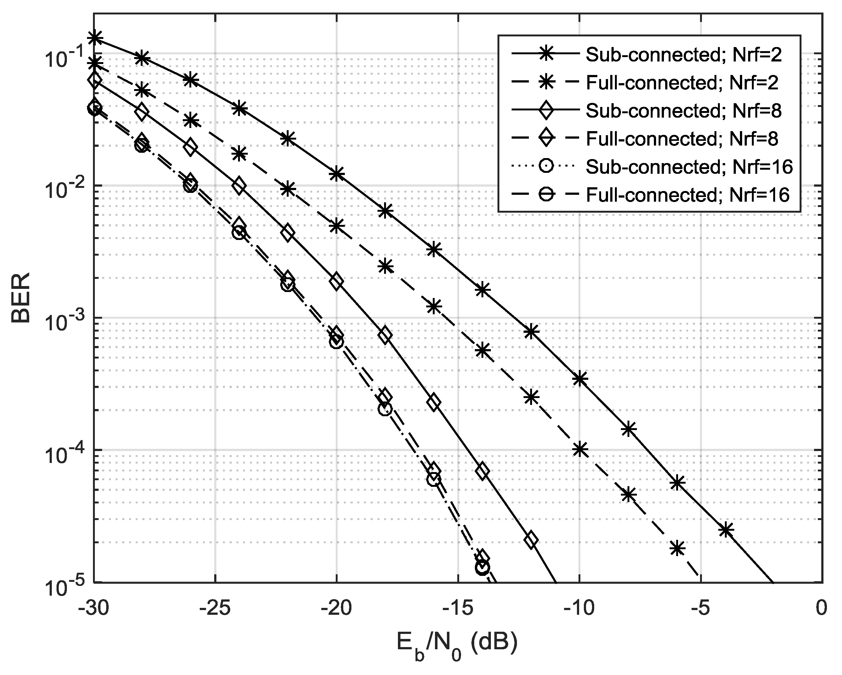
Figure 5.
Performance of the proposed hybrid sub-connected scheme for different numbers of quantization bits of the average AoD, .
Figure 5.
Performance of the proposed hybrid sub-connected scheme for different numbers of quantization bits of the average AoD, .

Figure 6.
Performance of the proposed hybrid sub-connected scheme for different numbers of quantization bits of the average AoD, .
Figure 6.
Performance of the proposed hybrid sub-connected scheme for different numbers of quantization bits of the average AoD, .

Table 1.
Main simulation parameters.
| Parameter | Values |
|---|---|
| Number of user (U) | 2, 4, and 8 |
| Number of Receive antennas () | 16 |
| Number of Transmit antennas () | 8 |
| Number of RF chains (R) | 2,8, and 16 |
| Number of subcarriers () | 64 |
| Cyclic prefix | 16 |
| Number of quantization bits (n) | 2, 4, and 6 |
| Carrier frequency | 72 GHz |
| Number of clusters () | 5 |
| Number of rays per cluster () | 3 |
© 2019 by the authors. Licensee MDPI, Basel, Switzerland. This article is an open access article distributed under the terms and conditions of the Creative Commons Attribution (CC BY) license (http://creativecommons.org/licenses/by/4.0/).
Share and Cite
MDPI and ACS Style
Castanheira, D.; Teodoro, S.; Simões, R.; Silva, A.; Gameiro, A. Multi-User Linear Equalizer and Precoder Scheme for Hybrid Sub-Connected Wideband Systems. Electronics 2019, 8, 436. https://doi.org/10.3390/electronics8040436
AMA Style
Castanheira D, Teodoro S, Simões R, Silva A, Gameiro A. Multi-User Linear Equalizer and Precoder Scheme for Hybrid Sub-Connected Wideband Systems. Electronics. 2019; 8(4):436. https://doi.org/10.3390/electronics8040436
Chicago/Turabian StyleCastanheira, Daniel, Sara Teodoro, Ricardo Simões, Adão Silva, and Atilio Gameiro. 2019. "Multi-User Linear Equalizer and Precoder Scheme for Hybrid Sub-Connected Wideband Systems" Electronics 8, no. 4: 436. https://doi.org/10.3390/electronics8040436
Note that from the first issue of 2016, this journal uses article numbers instead of page numbers. See further details here.