Small-Signal Stability Criteria in AC Distribution Systems—A Review


Abstract
:1. Introduction
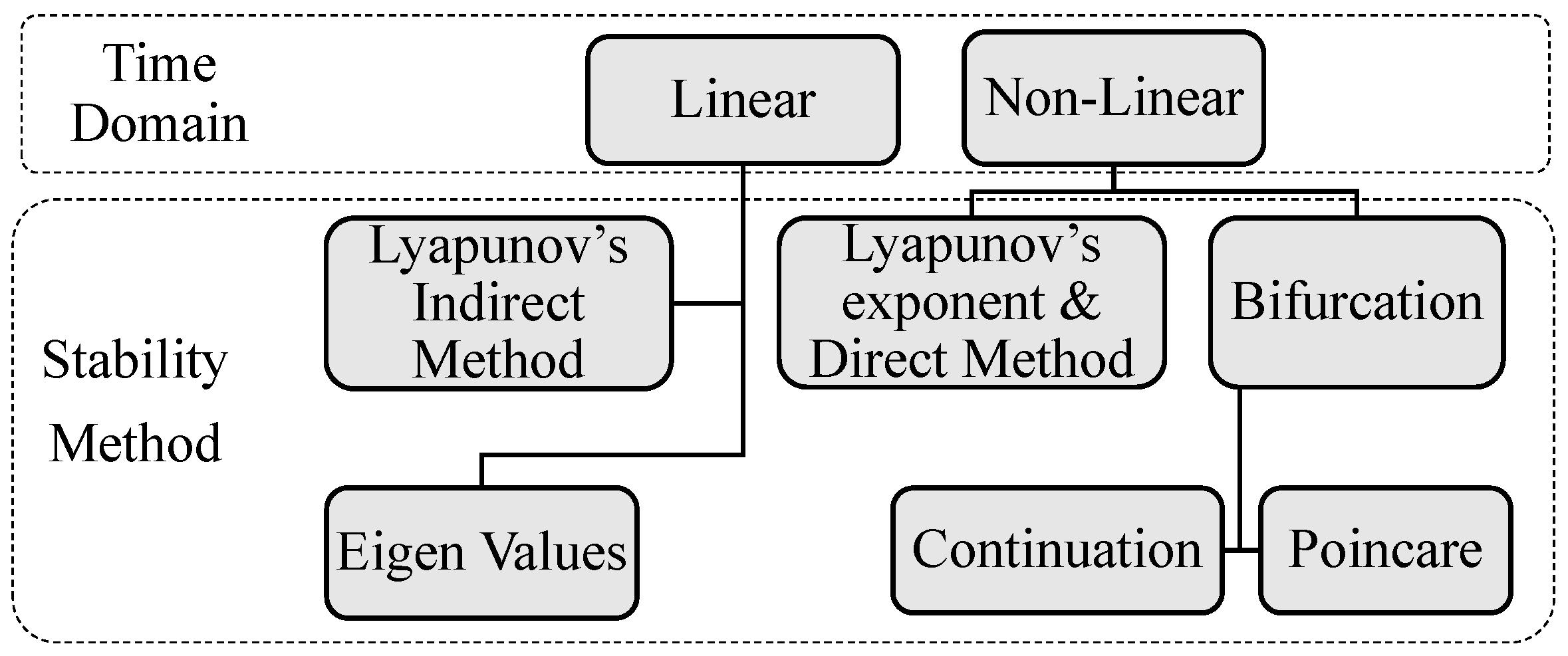
2. Small-Signal Stability Methods
3. Modelling and Analysis in Frequency Domain
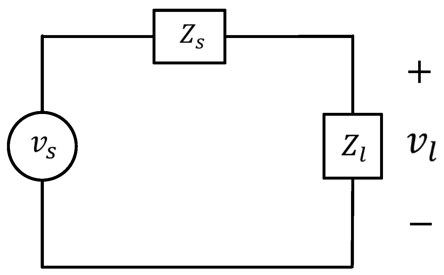
4. Impedance-Based Modelling and Analysis
5. Modelling and Analysis in SRF
5.1. Modelling and Analysis of Three-Phase AC Impedance
5.2. Modelling and Analysis of Single-Phase AC Impedance
6. Future Work
7. Summary
Author Contributions
Funding
Acknowledgments
Conflicts of Interest
References
- Rocabert, J.; Luna, A.; Blaabjerg, F.; Rodríguez, P. Control of Power Converters in AC Microgrids. IEEE Trans. Power Electron. 2012, 27, 4734–4749. [Google Scholar] [CrossRef]
- Siddique, M.N.; Ahmad, A.; Nawaz, M.K. Optimal integration of hybrid ( wind–solar ) system with diesel power plant using HOMER. Turk. J. Electr. Eng. Comput. Sci. 2015, 23, 1547–1557. [Google Scholar] [CrossRef]
- Matos, E.O.D.; Soares, T.M.; Bezerra, U.H.; De, M.E.; Tostes, L.; Rodrigo, A.; Manito, A.; Cordeiro, B.C., Jr. Using linear and non-parametric regression models to describe the contribution of non-linear loads on the voltage harmonic distortions in the electrical grid. IET Gener. Transm. Distrib. 2016, 1825–1832. [Google Scholar] [CrossRef]
- Bhattacharyya, S.; Cobben, S.; Ribeiro, P.; Kling, W. Harmonic emission limits and responsibilities at a point of connection. IET Gener. Transm. Distrib. 2012, 6, 256–264. [Google Scholar] [CrossRef]
- Middlebrook, R.; Cuk, S. A general unified approach to modelling switching-converter power stages. In Proceedings of the 1976 IEEE Power Electronics Specialists Conference, Cleveland, OH, USA, 8–10 June 1976; pp. 18–34. [Google Scholar] [CrossRef]
- Sudhoff, S.; Corzine, K.; Glover, S.; Hegner, H.; Robey, H. DC link stabilized field oriented control of electric propulsion systems. IEEE Trans. Energy Convers. 1998, 13, 27–33. [Google Scholar] [CrossRef]
- Sudhoff, S.; Glover, S.; Lamm, P.; Schmucker, D.; Delisle, D. Admittance space stability analysis of power electronic systems. IEEE Trans. Aerosp. Electron. Syst. 2000, 36, 965–973. [Google Scholar] [CrossRef]
- Emadi, A.; Khaligh, A.; Rivetta, C.; Williamson, G. Constant Power Loads and Negative Impedance Instability in Automotive Systems: Definition, Modeling, Stability, and Control of Power Electronic Converters and Motor Drives. IEEE Trans. Veh. Technol. 2006, 55, 1112–1125. [Google Scholar] [CrossRef]
- Feng, X.; Liu, J.; Lee, F. Impedance Specifications for Stable DC Distributed Power Systems. IEEE Trans. Power Electron. 2002, 17, 157–162. [Google Scholar] [CrossRef]
- Wildrick, C.; Lee, F.; Cho, B.; Choi, B. A method of defining the load impedance specification for a stable distributed power system. In Proceedings of the Proceedings of IEEE Power Electronics Specialist Conference, Seattle, WA, USA, 20–24 June 1993; pp. 826–832. [Google Scholar] [CrossRef]
- Liu, J.; Feng, X.; Lee, F.; Borojevich, D. Stability margin monitoring for DC distributed power systems via current/voltage perturbation. In Proceedings of the Sixteenth Annual IEEE Applied Power Electronics Conference and Exposition (Cat. No.01CH37181) APEC 2001, Anaheim, CA, USA, 4–8 March 2001; Volume 2, pp. 745–751. [Google Scholar] [CrossRef]
- Belkhayat, M.; Cooley, R.; Witulski, A. Large Signal Stability Criteria For Distributed Systems with Constant Power Loads. In Proceedings of the Power Electronics Specialist Conference, Atlanta, GA, USA, 18–22 June 1995; Volume 2, pp. 1333–1338. [Google Scholar] [CrossRef]
- Khaligh, A.; Rahimi, A.; Emadi, A. Negative Impedance Stabilizing Pulse Adjustment Control Technique for DC/DC Converters Operating in Discontinuous Conduction Mode and Driving Constant Power Loads. IEEE Trans. Veh. Technol. 2007, 56, 2005–2016. [Google Scholar] [CrossRef]
- Emadi, A.; Ehsani, M. Negative impedance stabilizing controls for PWM DC-DC converters using feedback linearization techniques. In Proceedings of the 35th Intersociety Energy Conversion Engineering Conference and Exhibit, Las Vegas, NV, USA, 24–28 July 2000; Volume 1, pp. 613–620. [Google Scholar]
- Grigore, V.; Hatonen, J.; Kyyra, J.; Suntio, T. Dynamics of a buck converter with a constant power load. In Proceedings of the 29th Annual IEEE Power Electronics Specialists Conference (Cat. No.98CH36196) PESC 98 Record, Fukuoka, Japan, 22 May 1998; Volume 1, pp. 72–78. [Google Scholar] [CrossRef]
- Liserre, M.; Teodorescu, R.; Blaabjerg, F. Stability of photovoltaic and wind turbine grid-connected inverters for a large set of grid impedance values. IEEE Trans. Power Electron. 2006, 21, 263–272. [Google Scholar] [CrossRef]
- Chen, M.; Sun, J. Low-Frequency Input Impedance Modeling of Boost Single-Phase PFC Converters. IEEE Trans. Power Electron. 2007, 22, 1402–1409. [Google Scholar] [CrossRef]
- Prodic, A. Compensator Design and Stability Assessment for Fast Voltage Loops of Power Factor Correction Rectifiers. IEEE Trans. Power Electron. 2007, 22, 1719–1730. [Google Scholar] [CrossRef]
- Jayabalan, R.; Fahimi, B. Naval Shipboard Power System. In Proceedings of the 2005 IEEE Vehicle Power and Propulsion Conference, Chicago, IL, USA, 7 September 2005; pp. 86–90. [Google Scholar] [CrossRef]
- Emadi, K.; Ehsani, M. Aircraft power systems: technology, state of the art, and future trends. IEEE Aerosp. Electron. Syst. Mag. 2000, 15, 28–32. [Google Scholar] [CrossRef]
- Wan, C.; Huang, M.; Tse, C.K.; Ruan, X. Stability of interacting grid-connected power converters. Proc. IEEE Int. Symp. Circuits Syst. 2014, 2668–2671. [Google Scholar] [CrossRef]
- Sun, J. Small-signal methods for AC distributed power systems—A review. IEEE Trans. Power Electron. 2009, 24, 2545–2554. [Google Scholar] [CrossRef]
- Sokal, N.O. System oscillations from negative input resistance at power input port of switching-mode regulator, amplifier, DC/DC converter, or DC/DC inverter. In Proceedings of the 1973 IEEE Power Electronics Specialists Conference, Pasadena, CA, USA, 11–13 June 1973; pp. 138–140. [Google Scholar] [CrossRef]
- Majumder, R. Some Aspects of Stability in Microgrids. IEEE Trans. Power Syst. 2012, 28, 3243–3252. [Google Scholar] [CrossRef]
- Iyer, S.V.; Belur, M.N.; Chandorkar, M.C. A Generalized Computational Method to Determine Stability of a Multi-inverter Microgrid. IEEE Trans. Power Electron. 2010, 25, 2420–2432. [Google Scholar] [CrossRef] [Green Version]
- Ghosh, A.; Ledwich, G. Stability of hysteretic controlled voltage source converters in a power system. In Proceedings of the 2011 IEEE PES Innovative Smart Grid Technologies, Perth, WA, Australia, 13–16 November 2011; pp. 1–8. [Google Scholar] [CrossRef]
- Wang, S.; Su, J.; Yang, X.; Du, Y.; Tu, Y.; Xu, H. A Review on the Small Signal Stability of Microgrid. In Proceedings of the 2016 IEEE 8th International Power Electronics and Motion Control Conference (IPEMC-ECCE Asia), Hefei, China, 22–26 May 2016. [Google Scholar]
- Amin, M.; Molinas, M. Small-Signal Stability Assessment of Power Electronics based Power Systems: A Discussion of Impedance and Eigenvalue-based Methods. IEEE Trans. Ind. Appl. 2017, 53, 5014–5030. [Google Scholar] [CrossRef]
- Kundur, P. Power System Stability and Control; McGraw- Hill: New York, NY, USA, 1994. [Google Scholar]
- Taylor, C. Power System Voltage Stability; McGraw-Hill: New York, NY, USA, 1994. [Google Scholar]
- Sanchez, S. Stability Investigation of Power Electronics Systems: A Microgrid Case. Ph.D. Thesis, Norwegian University of Science and Technology, Trondheim, Norway, 2015. [Google Scholar]
- Khalil, H.K. Nonlinear Systems, 2nd ed.; Prentice Hall: Englewood Cliffs, NJ, USA, 1996. [Google Scholar]
- Yao, Z.; Therond, P.G.; Davat, B. Stability analysis of power systems by the generalised Nyquist criterion. In Proceedings of the 1994 International Conference on Control—Control ’94, Coventry, UK, 21–24 March 1994; pp. 739–744. [Google Scholar]
- Xu, J.; Kanyingi, P.K.; Wang, K.; Li, G.; Han, B.; Jiang, X. Probabilistic small signal stability analysis with large scale integration of wind power considering dependence. Renew. Sustain. Energy Rev. 2016. [Google Scholar] [CrossRef]
- Moiola, C.G.; Moiola, J.L. Hopf Bifurcation Analysis: A Frequency Domain Approach; World Scientific: Singapore, 1996. [Google Scholar]
- Rygg, A.; Molinas, M.; Zhang, C.; Cai, X. A Modified Sequence-Domain Impedance Definition and Its Equivalence to the dq-Domain Impedance Definition for the Stability Analysis of AC Power Electronic Systems. IEEE J. Emerg. Sel. Top. Power Electron. 2016, 4, 1383–1396. [Google Scholar] [CrossRef] [Green Version]
- Rahman, A.U.; Syed, I.; Ullah, M. Small signal stability of a balanced three-phase ac microgrid using harmonic linearization: Parametric-based analysis. Electronics 2019, 8, 12. [Google Scholar] [CrossRef]
- Gelb, A.; Velde, W.E.V. Multiple-Input Describing Functions and Nonlinear System Design; McGraw-Hill: New York, NY, USA, 1968. [Google Scholar]
- El Aroudi, A.; Orabi, M.; Haroun, R.; Martinez-Salamero, L. Asymptotic Slow-Scale Stability Boundary of PFC AC-DC Power Converters: Theoretical Prediction and Experimental Validation. IEEE Trans. Ind. Electron. 2011, 58, 3448–3460. [Google Scholar] [CrossRef]
- Wang, X.; Blaabjerg, F.; Liserre, M.; Chen, Z.; He, J.; Li, Y. An Active Damper for Stabilizing Power-Electronics-Based AC Systems. IEEE Trans. Power Electron. 2014, 29, 3318–3329. [Google Scholar] [CrossRef]
- Wang, X.; Blaabjerg, F.; Wu, W. Modeling and analysis of harmonic stability in an AC power-electronics-based power system. IEEE Trans. Power Electron. 2014, 29, 6421–6432. [Google Scholar] [CrossRef]
- Schweizer, M.; Kolar, J.W. Shifting Input Filter Resonances—An Intelligent Converter Behavior for Maintaining System Stability. In Proceedings of the 2010 International Power Electronics Conference, Sapporo, Japan, 21–24 June 2010; pp. 906–913. [Google Scholar] [CrossRef]
- Radwan, A.A.A.; Mohamed, Y.A.R.I. Analysis and Active Suppression of AC- and DC-Side Instabilities in Grid-Connected Current-Source Converter-Based Photovoltaic System. IEEE Trans. Sustain. Energy 2013, 4, 630–642. [Google Scholar] [CrossRef]
- Chen, M.; Sun, J. Low-Frequency Input Impedance Models for Boost Single-Phase PFC Converters. In Proceedings of the 2005 IEEE 36th Power Electronics Specialists Conference, Recife, Brazil, 16 June 2005; pp. 1062–1068. [Google Scholar] [CrossRef]
- Sun, J.; Bing, Z. Input impedance modeling of single-phase PFC by the method of harmonic linearization. In Proceedings of the 2008 Twenty-Third Annual IEEE Applied Power Electronics Conference and Exposition, Austin, TX, USA, 24–28 February 2008; pp. 1188–1194. [Google Scholar] [CrossRef]
- Bing, Z.; Karimi, K.; Sun, J. Input Impedance Modeling and Analysis of Line-Commutated Rectifiers. IEEE Trans. Power Electron. 2009, 24, 2338–2346. [Google Scholar] [CrossRef]
- Bing, Z.; Sun, J. Input impedance modeling of multipulse rectifiers by double-fourier series method. In Proceedings of the 2010 IEEE Energy Conversion Congress and Exposition, Atlanta, GA, USA, 12–16 September 2010; Volume 24, pp. 3754–3761. [Google Scholar] [CrossRef]
- Sun, J.; Bing, Z.; Karimi, K.J. Small-signal modeling of multipulse rectifiers for more-electric aircraft applications. In Proceedings of the 2008 IEEE Power Electronics Specialists Conference, Rhodes, Greece, 15–19 June 2008; pp. 302–308. [Google Scholar] [CrossRef]
- Krein, P.T.; Bentsman, J.; Bass, R.M.; Lesieutre, B.L. On the Use of Averaging for the Analysis of Power Electronic Systems. IEEE Trans. Power Electron. 1990, 5, 182–190. [Google Scholar] [CrossRef]
- Burgos, R.; Boroyevich, D.; Wang, F.; Karimi, K.; Francis, G. On the AC stability of high power factor three-phase rectifiers. In Proceedings of the 2010 IEEE Energy Conversion Congress and Exposition, Atlanta, GA, USA, 12–16 September 2010; pp. 2047–2054. [Google Scholar] [CrossRef]
- Wen, B.; Boroyevich, D.; Mattavelli, P.; Shen, Z.; Burgos, R. Experimental Verification of the Generalized Nyquist Stability Criterion for Balanced Three-phase Ac Systems in the Presence of Constant Power Loads. In Proceedings of the 2012 IEEE Energy Conversion Congress and Exposition (ECCE), Raleigh, NC, USA, 15–20 September 2012; pp. 3926–3933. [Google Scholar] [CrossRef]
- Belkhayat, M. Stability Criteria for AC Power Systems with Regulated Loads. Ph.D. Thesis, Purdue University, West Lafayette, IN, USA, 1997. [Google Scholar]
- MacFarlane, A.G.J.; Postlethwaite, I. The generalized Nyquist stability criterion and multivariable root loci. Int. J. Control 1977, 25, 81–127. [Google Scholar] [CrossRef]
- Wen, B.; Boroyevich, D.; Burgos, R.; Mattavelli, P.; Shen, Z. Small-Signal Stability Analysis of Three-Phase AC Systems in the Presence of Constant Power Loads Based on Measured D-Q Frame Impedances. IEEE Trans. Power Electron. 2015, 30, 5952–5963. [Google Scholar] [CrossRef]
- Familiant, Y.A.; Huang, J.; Corzine, K.A.; Belkhayat, M. New Techniques for Measuring Impedance Characteristics of Three-Phase AC Power Systems. IEEE Trans. Power Electron. 2009, 24, 1802–1810. [Google Scholar] [CrossRef]
- Francis, G.; Burgos, R.; Boroyevich, D.; Wang, F.; Karimi, K. An Algorithm and Implementation System for Measuring Impedance in the D-Q Domain. In Proceedings of the 2011 IEEE Energy Conversion Congress and Exposition, Phoenix, AZ, USA, 17–22 September 2011; pp. 3221–3228. [Google Scholar] [CrossRef]
- Shen, Z.; Jaksic, M.; Zhou, B.; Mattavelli, P.; Boroyevich, D.; Verhulst, J.; Belkhayat, M. Analysis of Phase Locked Loop (PLL) influence on dq impedance measurement in three-phase AC systems. In Proceedings of the 2013 Twenty-Eighth Annual IEEE Applied Power Electronics Conference and Exposition (APEC), Long Beach, CA, USA, 17–21 March 2013; pp. 939–945. [Google Scholar] [CrossRef]
- Polak, E. Frequency-response methods in control systems. Proc. IEEE 1981, 69, 1596. [Google Scholar] [CrossRef]
- Burgos, R.; Boroyevich, D.; Wang, F.; Karimi, K.; Francis, G. Ac stability of high power factor multi-pulse rectifiers. In Proceedings of the 2011 IEEE Energy Conversion Congress and Exposition, Phoenix, AZ, USA, 17–22 September 2011; pp. 3758–3765. [Google Scholar] [CrossRef]
- Harris, M.; Kelley, A.; Rhode, J.; Baran, M. Instrumentation for measurement of line impedance. In Proceedings of the 1994 IEEE Applied Power Electronics Conference and Exposition, Orlando, FL, USA, 13–17 February 1994; pp. 887–893. [Google Scholar] [CrossRef]
- Feng, X.; Lee, F. On-line measurement on stability margin of DC distributed power system. In Proceedings of the Fifteenth Annual IEEE Applied Power Electronics Conference and Exposition, New Orleans, LA, USA, 6–10 February 2000; Volume 2, pp. 1190–1196. [Google Scholar]
- Feng, X.; Ye, Z.; Xing, K.; Lee, F.; Borojevic, D. Individual load impedance specification for a stable DC distributed power system. In Proceedings of the Fourteenth Annual Applied Power Electronics Conference and Exposition, Dallas, TX, USA, 14–18 March 1999; Volume 2, pp. 923–929. [Google Scholar] [CrossRef]
- Familiant, Y.; Corzine, K.; Huang, J.; Belkhayat, M. AC Impedance Measurement Techniques. In Proceedings of the IEEE International Conference on Electric Machines and Drives, San Antonio, TX, USA, 15 May 2005; pp. 1850–1857. [Google Scholar] [CrossRef]
- Mao, H.; Boroyevich, D.; Lee, F. Novel reduced-order small-signal model of three-phase PWM rectifiers and its application in control design and system analysis. In Proceedings of the 27th Annual IEEE Power Electronics Specialists Conference, Baveno, Italy, 23–27 June 1996; Volume 1, pp. 556–562. [Google Scholar] [CrossRef]
- Francis, G. An Algorithm and System for Measuring Impedance in D-Q Coordinates. Ph.D. Thesis, Virginia Polytechnic Institute and State University, Blacksburg, Virginia, 2010. [Google Scholar]
- Belkhayat, M.; Williams, M.L. Impedance Extraction Techniques for DC and AC Systems. In Proceedings of the Naval Symposium on Electric Machines, Philadelphia, PA, USA, 4–7 December 2000. [Google Scholar]
- Shen, Z.; Jaksic, M.; Mattavelli, P.; Boroyevich, D.; Verhulst, J.; Belkhayat, M. Three-phase AC system impedance measurement unit (IMU) using chirp signal injection. In Proceedings of the 2013 Twenty-Eighth Annual IEEE Applied Power Electronics Conference and Exposition, Long Beach, CA, USA, 17–21 March 2013; pp. 2666–2673. [Google Scholar] [CrossRef]
- Huang, J. AC/DC Power System Small-Signal Impedance Measurement for Stability Analysis. Ph.D. Thesis, Missouri University of Science and Technology, Rolla, MO, USA, 2009. [Google Scholar]
- Wen, B.; Boroyevich, D.; Burgos, R.; Mattavelli, P. Input impedance of voltage source converter with stationary frame linear current regulators and phase-locked loop. In Proceedings of the 2013 IEEE Energy Conversion Congress and Exposition, Denver, CO, USA, 15–19 September 2013; pp. 4207–4213. [Google Scholar] [CrossRef]
- Valdivia, V.; Lázaro, A.; Barrado, A.; Zumel, P.; Fernández, C.; Sanz, M. Impedance Identification Procedure of Three-Phase Balanced Voltage Source Inverters Based on Transient Response Measurements. IEEE Trans. Power Electron. 2011, 26, 3810–3816. [Google Scholar] [CrossRef]
- Huang, J.; Corzine, K.A.; Belkhayat, M. Small-Signal Impedance Measurement of Power-Electronics-Based AC Power Systems Using Line-to-Line Current Injection. IEEE Trans. Power Electron. 2009, 24, 445–455. [Google Scholar] [CrossRef]
- Huang, J.; Corzine, K. AC Impedance Measurement by Line-to-Line Injected Current. In Proceedings of the Conference Record of the 2006 IEEE Industry Applications Conference Forty-First IAS Annual Meeting, Tampa, FL, USA, 8–12 October 2006; Volume 1, pp. 300–306. [Google Scholar] [CrossRef]
- Shen, Z.; Jaksic, M.; Mattavelli, P.; Boroyevich, D.; Verhulst, J.; Belkhayat, M. Design and implementation of three-phase AC impedance measurement unit (IMU) with series and shunt injection. In Proceedings of the 2013 Twenty-Eighth Annual IEEE Applied Power Electronics Conference and Exposition (APEC), Long Beach, CA, USA, 17–21 March 2013; pp. 2674–2681. [Google Scholar] [CrossRef]
- Jaksic, M.; Shen, Z.; Cvetkovic, I.; Boroyevich, D.; Burgos, R.; Mattavelli, P. Multi-level single-phase shunt current injection converter used in small-signal dq impedance identification. In Proceedings of the 2014 IEEE Applied Power Electronics Conference and Exposition, Fort Worth, TX, USA, 16–20 March 2014; pp. 2775–2782. [Google Scholar] [CrossRef]
- Busada, C.A.; Gomez Jorge, S.; Leon, A.E.; Solsona, J.A. Current Controller Based on Reduced Order Generalized Integrators for Distributed Generation Systems. IEEE Trans. Ind. Electron. 2012, 59, 2898–2909. [Google Scholar] [CrossRef]
- Liserre, M.; Teodorescu, R.; Blaabjerg, F. Stability of grid-connected PV inverters with large grid impedance variation. In Proceedings of the 2004 IEEE 35th Annual Power Electronics Specialists Conference, Aachen, Germany, 20–25 June 2004; pp. 4773–4779. [Google Scholar] [CrossRef]
- Familiant, Y.L. AC Impedance Measurement Techniques in Power Systems. Ph.D. Thesis, University of Wisconsin, Milwaukee, WI, USA, 2006. [Google Scholar]
- Harnefors, L. Modeling of Three-Phase Dynamic Systems Using Complex Transfer Functions and Transfer Matrices. IEEE Trans. Ind. Electron. 2007, 54, 2239–2248. [Google Scholar] [CrossRef]
- Harnefors, L.; Bongiorno, M.; Lundberg, S. Input-Admittance Calculation and Shaping for Controlled Voltage-Source Converters. IEEE Trans. Ind. Electron. 2007, 54, 3323–3334. [Google Scholar] [CrossRef]
- Huang, J.; Corzine, K.; Belkhayat, M. Single-Phase AC Impedance Modeling for Stability of Integrated Power Systems. In Proceedings of the 2007 IEEE Electric Ship Technologies Symposium, Arlington, VA, USA, 21–23 May 2007; pp. 483–489. [Google Scholar] [CrossRef]
- Turner, R.; Walton, S.; Duke, R. Stability and Bandwidth Implications of Digitally Controlled Grid-Connected Parallel Inverters. IEEE Trans. Ind. Electron. 2010, 57, 3685–3694. [Google Scholar] [CrossRef] [Green Version]
- Rodriguez, P.; Luna, A.; Candela, I.; Mujal, R.; Teodorescu, R.; Blaabjerg, F. Multiresonant Frequency-Locked Loop for Grid Synchronization of Power Converters Under Distorted Grid Conditions. IEEE Trans. Ind. Electron. 2011, 58, 127–138. [Google Scholar] [CrossRef] [Green Version]
- Jaksic, M.; Boroyevich, D.; Burgos, R.; Shen, Z.; Cvetkovic, I.; Mattavelli, P. Modular interleaved single-phase series voltage injection converter used in small-signal dq impedance identification. In Proceedings of the 2014 IEEE Energy Conversion Congress and Exposition (ECCE), Pittsburgh, PA, USA, 14–18 September 2014; pp. 3036–3045. [Google Scholar] [CrossRef]
- Roinila, T.; Vilkko, M. Broadband Methods for Online Grid Impedance Measurement. In Proceedings of the 2013 IEEE Energy Conversion Congress and Exposition, Denver, CO, USA, 15–19 September 2013; pp. 3003–3010. [Google Scholar] [CrossRef]
- Roinila, T.; Vilkko, M.; Sun, J. Online Grid Impedance Measurement Using Discrete-Interval Binary Sequence Injection. IEEE J. Emerg. Sel. Top. Power Electron. 2014, 2, 985–993. [Google Scholar] [CrossRef]
- Xiao, P.; Venayagamoorthy, G.K.; Corzine, K.A.; Huang, J. Recurrent Neural Networks Based Impedance Measurement Technique for Power Electronic Systems. IEEE Trans. Power Electron. 2010, 25, 382–390. [Google Scholar] [CrossRef]
- Cobreces, S.; Bueno, E.J.; Pizarro, D.; Rodriguez, F.J.; Huerta, F.; Member, S. Grid Impedance Monitoring System for Distributed Power Generation Electronic Interfaces. IEEE Trans. Instrum. Meas. 2009, 58, 3112–3121. [Google Scholar] [CrossRef]
- Cespedes, M.; Sun, J. Adaptive Control of Grid-Connected Inverters Based on Online Grid Impedance Measurements. IEEE Trans. Sustain. Energy 2014, 5, 516–523. [Google Scholar] [CrossRef]
- Ciobotaru, M.; Agelidis, V.; Member, S.; Member, S.; G, E.E.B.; Nsw, U.S. Line impedance estimation using model based identification technique. In Proceedings of the 2011 14th European Conference on Power Electronics and Applications, Birmingham, UK, 30 August–1 September 2011; pp. 15–21. [Google Scholar]
- Hoffmann, N.; Fuchs, F.W. Minimal Invasive Equivalent Grid Impedance Estimation in Inductive-Resistive Power Networks Using Extended Kalman Filter. IEEE Trans. Power Electron. 2014, 29, 631–641. [Google Scholar] [CrossRef]
- Dong, D.; Wen, B.; Boroyevich, D.; Mattavelli, P.; Xue, Y. Analysis of Phase-Locked Loop Low-Frequency Stability in Three-Phase Grid-Connected Power Converters Considering Impedance Interactions. IEEE Trans. Ind. Electron. 2015, 62, 310–321. [Google Scholar] [CrossRef]
- Cespedes, M.; Sun, J. Impedance Modeling and Analysis of Grid-Connected Voltage-Source Converters. IEEE Trans. Power Electron. 2014, 29, 1254–1261. [Google Scholar] [CrossRef]
- Wen, B.; Dong, D.; Boroyevich, D.; Burgos, R.; Mattavelli, P.; Shen, Z. Impedance-Based Analysis of Grid-Synchronization Stability for Three-Phase Paralleled Converters. IEEE Trans. Power Electron. 2016, 31, 26–38. [Google Scholar] [CrossRef]
- Wen, B.; Boroyevich, D.; Burgos, R.; Mattavelli, P.; Shen, Z. Analysis of D-Q Small-Signal Impedance of Grid-Tied Inverters. IEEE Trans. Power Electron. 2016, 31, 675–687. [Google Scholar] [CrossRef]
- Valdivia, V.; Lazaro, A.; Barrado, A.; Zumel, P.; Fernandez, C.; Sanz, M. Black-Box Modeling of Three-Phase Voltage Source Inverters for System-Level Analysis. IEEE Trans. Ind. Electron. 2012, 59, 3648–3662. [Google Scholar] [CrossRef]
- Turner, R.; Walton, S.; Duke, R. A Case Study on the Application of the Nyquist Stability Criterion as applied to Interconnected Loads and Sources on Grids. IEEE Trans. Ind. Electron. 2013, 60, 2740–2749. [Google Scholar] [CrossRef]
- Desoer, C.; Wang, Y.-T. On the generalized nyquist stability criterion. IEEE Trans. Automat. Contr. 1980, 25, 187–196. [Google Scholar] [CrossRef]
- Liu, Z.; Liu, J.; Bao, W.; Zhao, Y. Infinity-Norm of Impedance-Based Stability Criterion for Three-Phase AC Distributed Power Systems With Constant Power Loads. IEEE Trans. Power Electron. 2015, 30, 3030–3043. [Google Scholar] [CrossRef]
- Wildrick, C.; Lee, F.; Cho, B.; Choi, B. A method of defining the load impedance specification for a stable distributed power system. IEEE Trans. Power Electron. 1995, 10, 280–285. [Google Scholar] [CrossRef]
- Sun, J. Impedance-Based Stability Criterion for Grid-Connected Inverters. IEEE Trans. Power Electron. 2011, 26, 3075–3078. [Google Scholar] [CrossRef]
- Liu, Z.; Liu, J.; Wang, H. Output Impedance Modeling and Stability Criterion for Parallel Inverters with Average Load Sharing Scheme in AC Distributed Power System. In Proceedings of the 2012 Twenty-Seventh Annual IEEE Applied Power Electronics Conference and Exposition (APEC), Orlando, FL, USA, 5–9 February 2012; pp. 1921–1926. [Google Scholar]
- Hou, L.; Liu, B.; Shi, H.; Yi, H.; Zhuo, F. New techniques for measuring islanded microgrid impedance characteristics based on current injection. In Proceedings of the 2014 International Power Electronics Conference, Hiroshima, Japan, 18–21 May 2014; pp. 577–581. [Google Scholar] [CrossRef]
- Park, R.H. Two-reaction theory of synchronous machines generalized method of analysis-part I. Trans. Am. Inst. Electr. Eng. 1929, 48, 716–727. [Google Scholar] [CrossRef]
- Park, R.H. Two-reaction theory of synchronous machines Part II. Electr. Eng. 1933, 52, 44–45. [Google Scholar] [CrossRef]
- Hiti, S.; Boroyevich, D. Small-signal modeling of three-phase PWM modulators. In Proceedings of the 27th Annual IEEE Power Electronics Specialists Conference PESC Record, Baveno, Italy, 23–27 June 1996; Volume 1, pp. 550–555. [Google Scholar] [CrossRef]
- Rodriguez, P.; Lunar, A.; Teodorescu, R.; Iov, F.; Blaabjerg, F. Fault ride-through capability implementation in wind turbine converters using a decoupled double synchronous reference frame PLL. In Proceedings of the 2007 European Conference on Power Electronics and Applications, Aalborg, Denmark, 2–5 September 2007; pp. 1–10. [Google Scholar] [CrossRef]
- Santos Filho, R.M.; Seixas, P.F.; Cortizo, P.C.; Torres, L.A.B.; Souza, A.F. Comparison of Three Single-Phase PLL Algorithms for UPS Applications. IEEE Trans. Ind. Electron. 2008, 55, 2923–2932. [Google Scholar] [CrossRef]
- Shinnaka, S. A Robust Single-Phase PLL System With Stable and Fast Tracking. IEEE Trans. Ind. Appl. 2008, 44, 624–633. [Google Scholar] [CrossRef]
- Rodriguez, P.; Pou, J.; Bergas, J.; Candela, J.I.; Burgos, R.P.; Boroyevich, D. Decoupled Double Synchronous Reference Frame PLL for Power Converters Control. IEEE Trans. Power Electron. 2007, 22, 584–592. [Google Scholar] [CrossRef]
- Cespedes, M.; Sun, J. Renewable Energy Systems Instability Involving Grid-Parallel Inverters. In Proceedings of the 2009 Twenty-Fourth Annual IEEE Applied Power Electronics Conference and Exposition, Washington, DC, USA, 15–19 February 2009; pp. 1971–1977. [Google Scholar] [CrossRef]
- Acevedo, S.S.; Molinas, M. Power electronics modeling fidelity: Impact on stability estimate of micro-grid systems. In Proceedings of the 2011 IEEE PES Innovative Smart Grid Technologies, Perth, WA, Australia, 13–16 November 2011; pp. 1–8. [Google Scholar] [CrossRef]


| Model | Detail | Advantage | Disadvantage | Ref. |
|---|---|---|---|---|
| Lyapunov indirect | Use eigenvalue to estimate stability | Can determine the stability of the entire system globally for an operating point. | It requires detailed modelling of entire system. Its converter model cannot identify the sustained harmonics. | [28,29,30,31,32,33] |
| Lyapunov direct | Use positive definite function and its derivative in state space | Can apply to small systems | Not suitable for large-scale systems | [29,30,31,32,33] |
| Probabilistic Numerical methods | Different types including Monte Carlo simulation method | Capable of analyzing a complex & large-scale system with high accuracy. | Time-consuming method. Huge computation efforts required | [34] |
| Probabilistic Analytical Methods | Cumulant-based method | Low computation efforts required so can deal with large-scale system. | Inaccurate in some situations due to inaccurate first order approximation | [34] |
| Probabilistic Approximate Methods | Point Estimation method (PEM) | Attains quick convergence, a low computational effort is required and can work for large-scale system | Applicability to large-scale system depends on applied scheme, requires complex formulation | [34] |
| Phasor Model | Estimate stability in time domain | Can be linearized using state-space methods if model is not large. | Dimensions are significantly higher. It is not differentiable often | [22] |
| Bifurcation | Apply mathematical approach to ordinary differential equations (ODEs) to extract eigenvalues | Performs very well for small system i.e., up to 2nd order ODEs | Slow for higher order ODEs | [35] |
| Model | Detail | Advantage | Disadvantage | Ref. |
|---|---|---|---|---|
| Bifurcation | Apply Laplace transform to non-linear ODEs | Work well for higher order system as well | More complicated | [35] |
| SRF | Extract impedance using SRF technique to estimate stability | Detailed modelling is not required. It can deal with large system. | Only work for balanced 3-phase or pure single-phase | [22,28] |
| Harmonic Linearization | Extract impedance by injecting a specific harmonic component | Work for both unbalanced 3-phase and combination for 1-phase and 3-phase | Limited observability of certain states | [22,28] |
| Impedance | ||||
|---|---|---|---|---|
| Extraction | Detail | Advantage | Disadvantage | Ref. |
| Technique | ||||
| Bridge converter (three-phase) | Three-phase bridge converter or a shunt-connected power converter was used for current injection | The accurate control of the injected currents. | Limitations for measuring high frequencies. Pulse width modulation (PWM) needs to be a multiple of the injected frequency | [55,77] |
| Three-Phase Chopper Circuit | Modulates a three-phase shunt-connected resistive impedance using a three-phase chopper circuit | The switching frequency is set to the injected frequency and is very low compared to the full-bridge circuit. | The injected current will have considerable harmonics | [55,77] |
| Three-Phase Wound-Rotor Induction Machine (WRIM) | Used to inject a perturbation into the system. The machine injects onto all three phases as it rotates. | Can produce the same quality injection current as bridge converter and is suitable for low-, medium-, and high-voltage systems. | The WRIM must be at specific location. Induction machine must be sized for each application and power level. | [55,77] |
| Single-phase current injection | The impedance in SRF can be determined by injecting line-to-line current between two lines. | (1) Simpler to construct, requires less components, reduced cost, straightforward implementation. (2) Can be used for both ac and dc systems. | The injected current will have considerable harmonics (depending upon type of injection device) | [71,72] |
| Impedance | ||||
|---|---|---|---|---|
| Extraction | Detail | Advantage | Disadvantage | Ref. |
| Technique | ||||
| Maximum-length binary sequence (MLBS) | uses maximum-length binary sequence (MLBS) injection and averaging Fourier techniques to overcome the drawbacks of impulse injection | cost effective, easy data acquisition, can work under low SNR and tight amplitude restrictions, straightforward generation of sequence | Requires low noise floor | [84] |
| Discrete interval binary sequence (DIBS) | It is one class of pseudorandom sequences, in which the power spectrum can be specified by the user. | Energy at the harmonic frequencies can be increased up to eight times compared with MLBS, so perturbation injection is minimized | Strong grid conditions are required. Perturbation may create harmonics & nonlinearities. | [85] |
| Chirp Signal (also called a swept-sine signal) | Signal with wide bandwidth and low crest factor is injected into three-phase | Low crest factor so low perturbation level & wide bandwidth. Reduce measurement time. | More susceptible to noise | [67] |
| Recurrent Neural Networks Based Impedance Measurement | Random PWM signals and resistive chopper circuits are used to inject perturbation signals into the system | Much smaller number of online injections are needed. Impedance extraction is more consistent due to stable operating point. Reduces online test time. | Training is required to obtain impedance information at any frequency within the range of interest. | [86] |
| Signal | Hilbert Transform |
|---|---|
© 2019 by the authors. Licensee MDPI, Basel, Switzerland. This article is an open access article distributed under the terms and conditions of the Creative Commons Attribution (CC BY) license (http://creativecommons.org/licenses/by/4.0/).
Share and Cite
Rahman, A.U.; Syed, I.; Ullah, M. Small-Signal Stability Criteria in AC Distribution Systems—A Review. Electronics 2019, 8, 216. https://doi.org/10.3390/electronics8020216
Rahman AU, Syed I, Ullah M. Small-Signal Stability Criteria in AC Distribution Systems—A Review. Electronics. 2019; 8(2):216. https://doi.org/10.3390/electronics8020216
Chicago/Turabian StyleRahman, Atta Ur, Irtaza Syed, and Mukhtar Ullah. 2019. "Small-Signal Stability Criteria in AC Distribution Systems—A Review" Electronics 8, no. 2: 216. https://doi.org/10.3390/electronics8020216