A Receiving Antenna Allocation Scheme for Downlink MU-MIMO-OFDM Transmission

Abstract
:1. Introduction
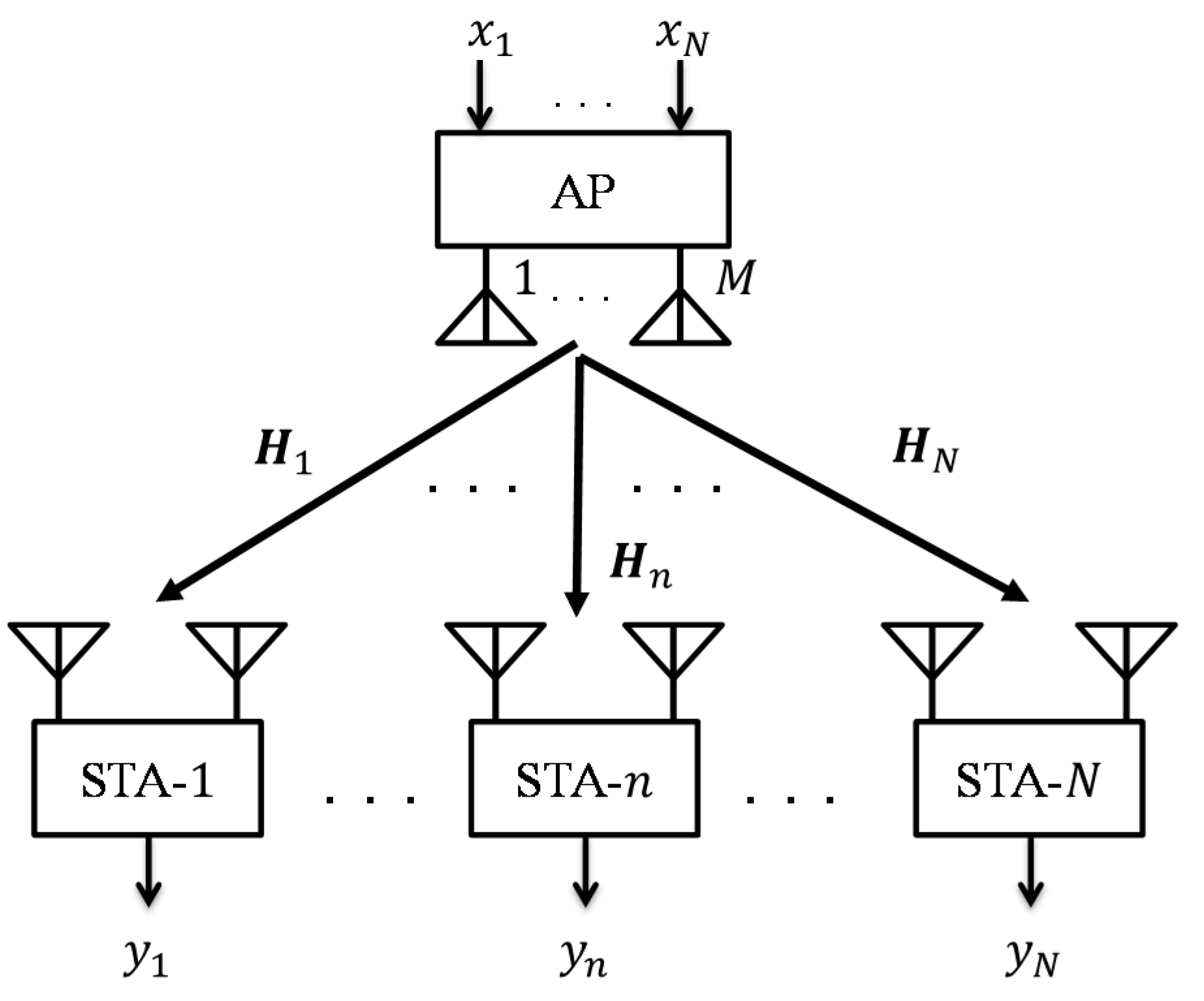
2. System Model
3. Proposed Scheme
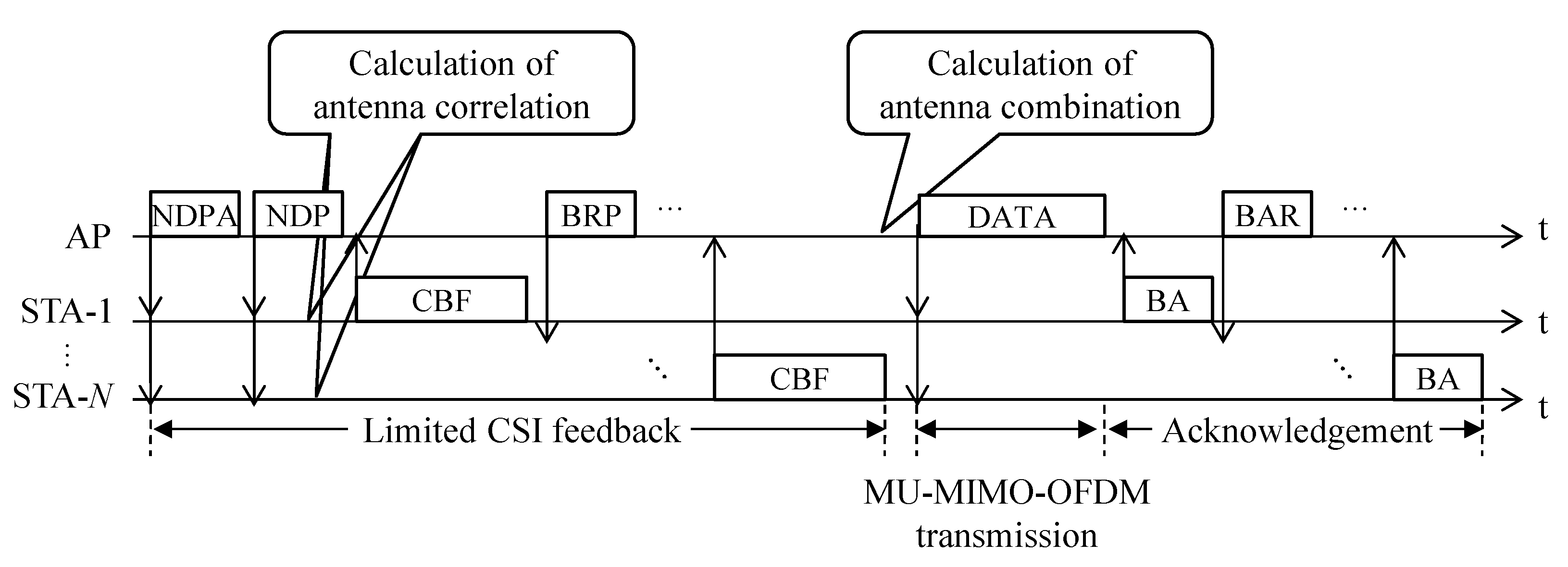
3.1. Limited CSI Feedback Sequence
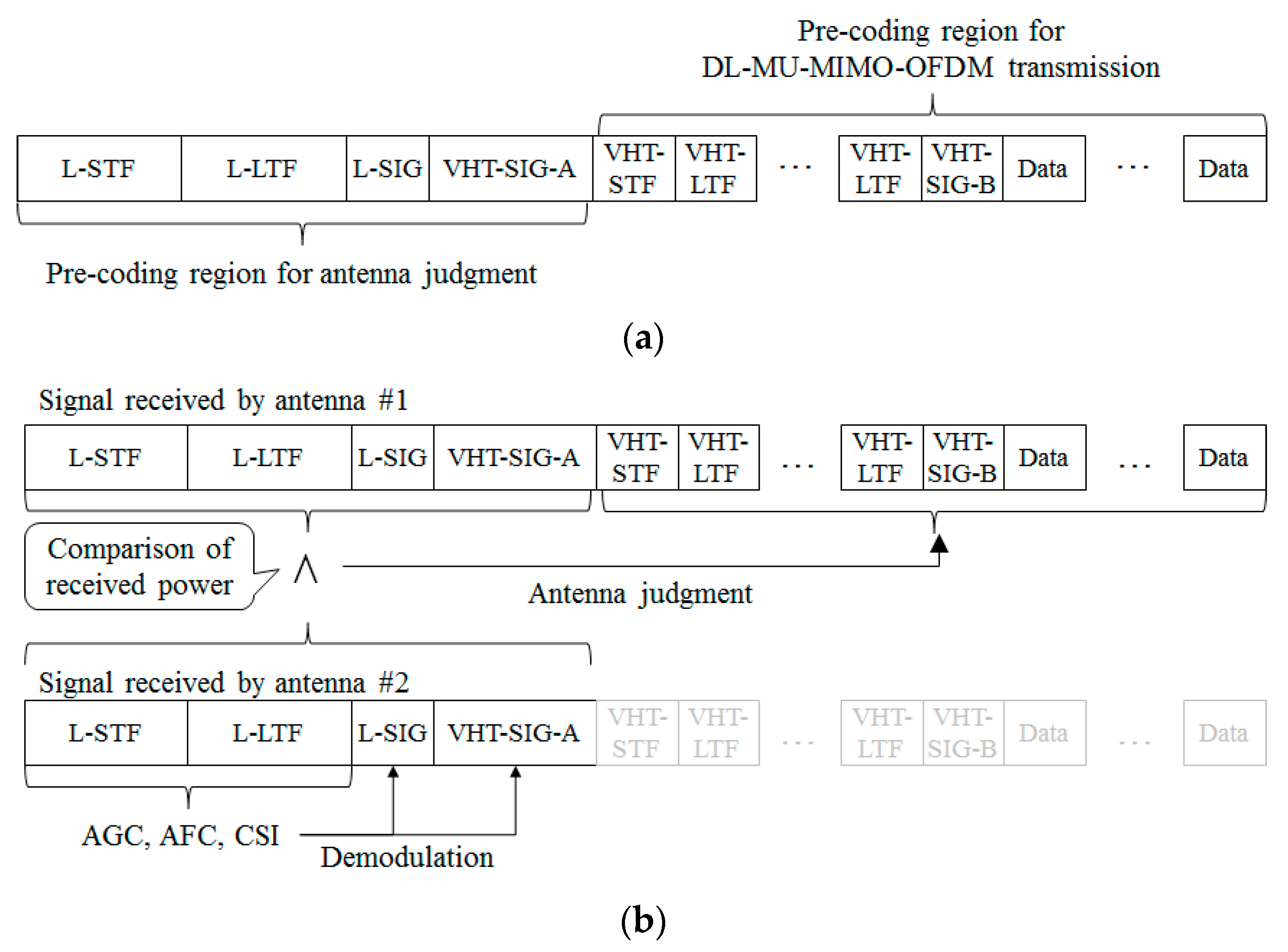
3.2. Receiving Antenna Decision Method
4. Performance Evaluation
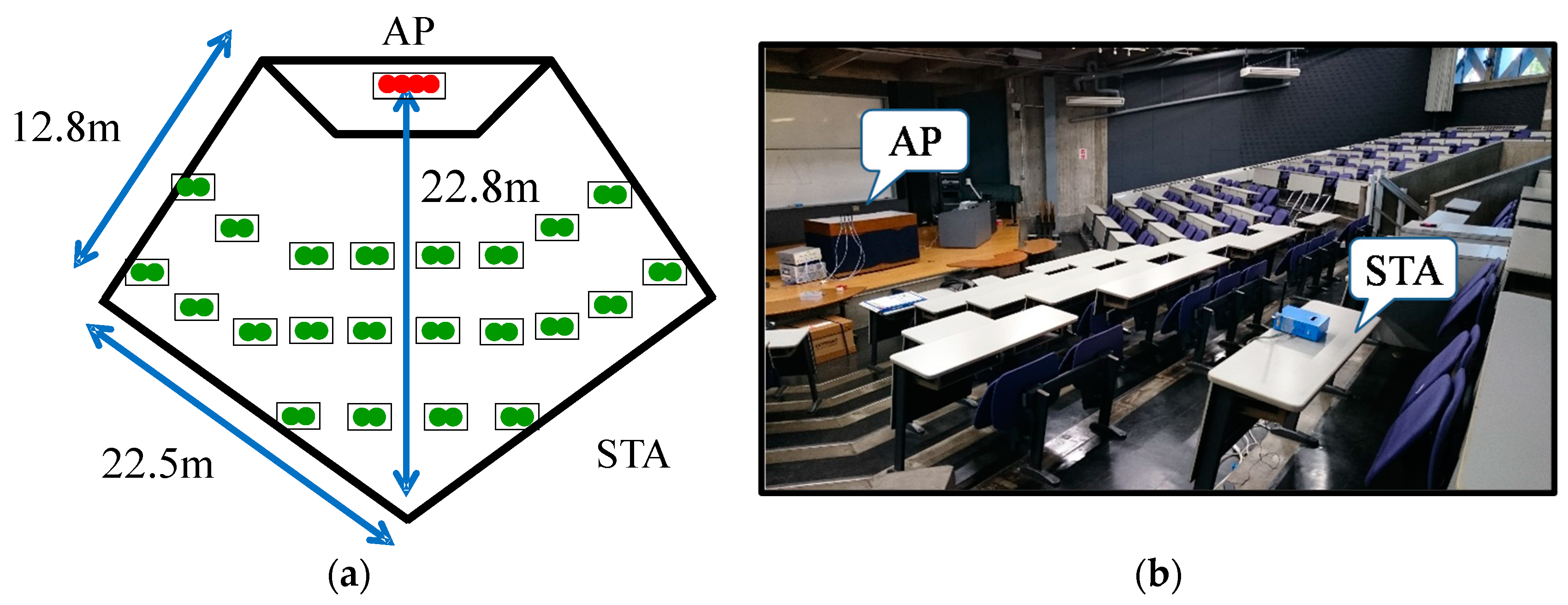
4.1. Experimental Measurements of Channel Responses
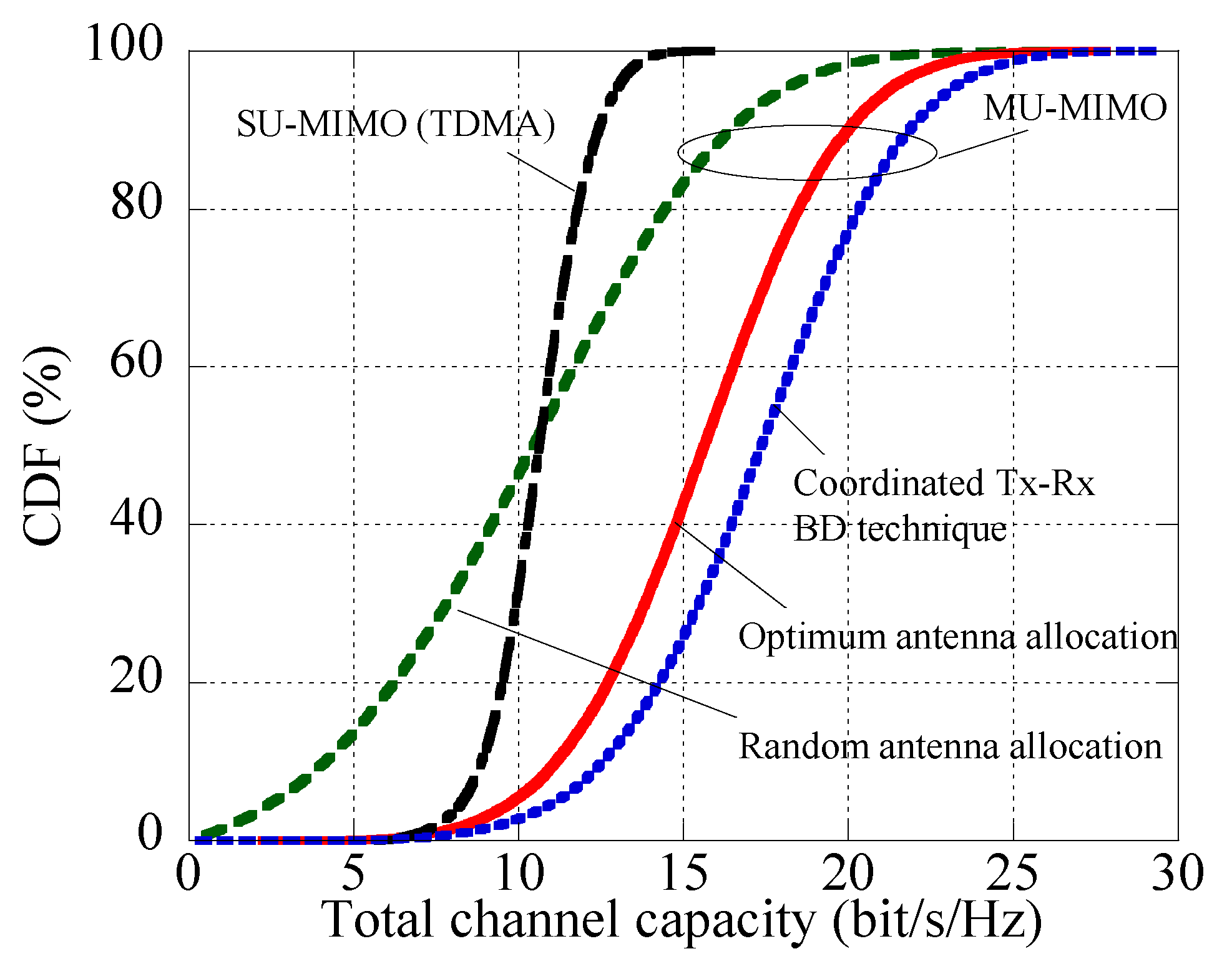
4.2. Validity of DL-MU-MIMO-OFDM Transmission Using Receiving Antenna Allocation
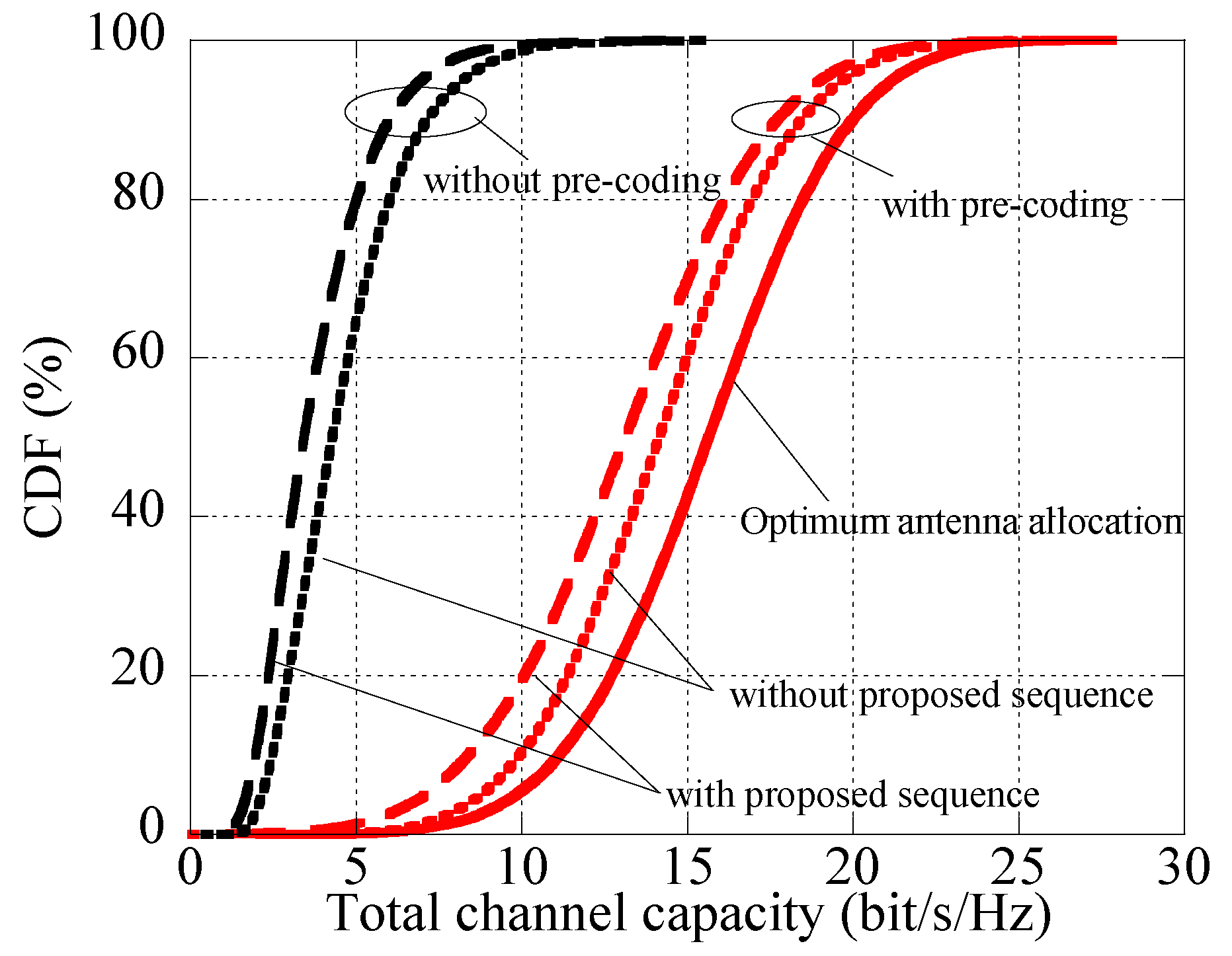
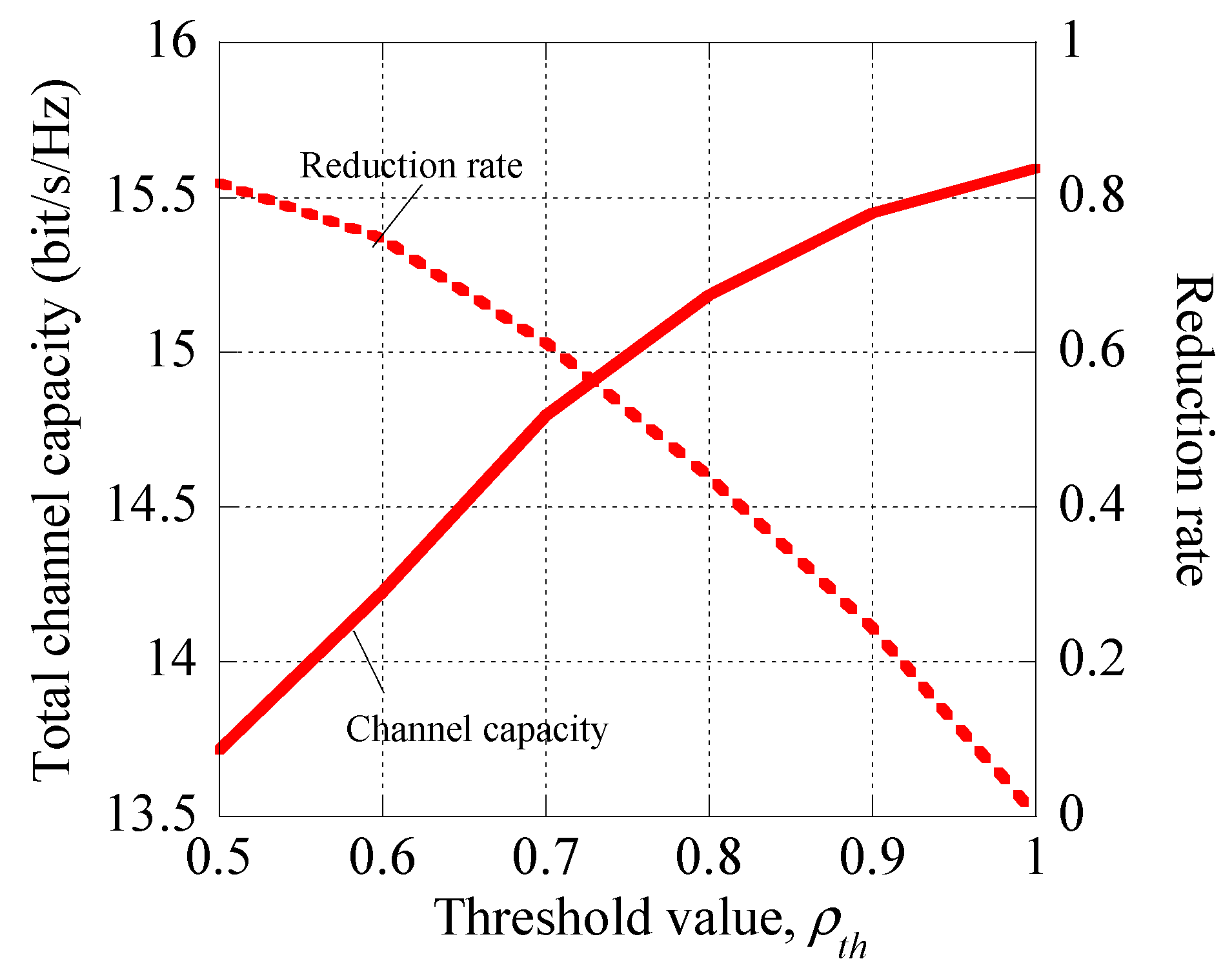
4.3. Analysis of Limited CSI Feedback Sequence
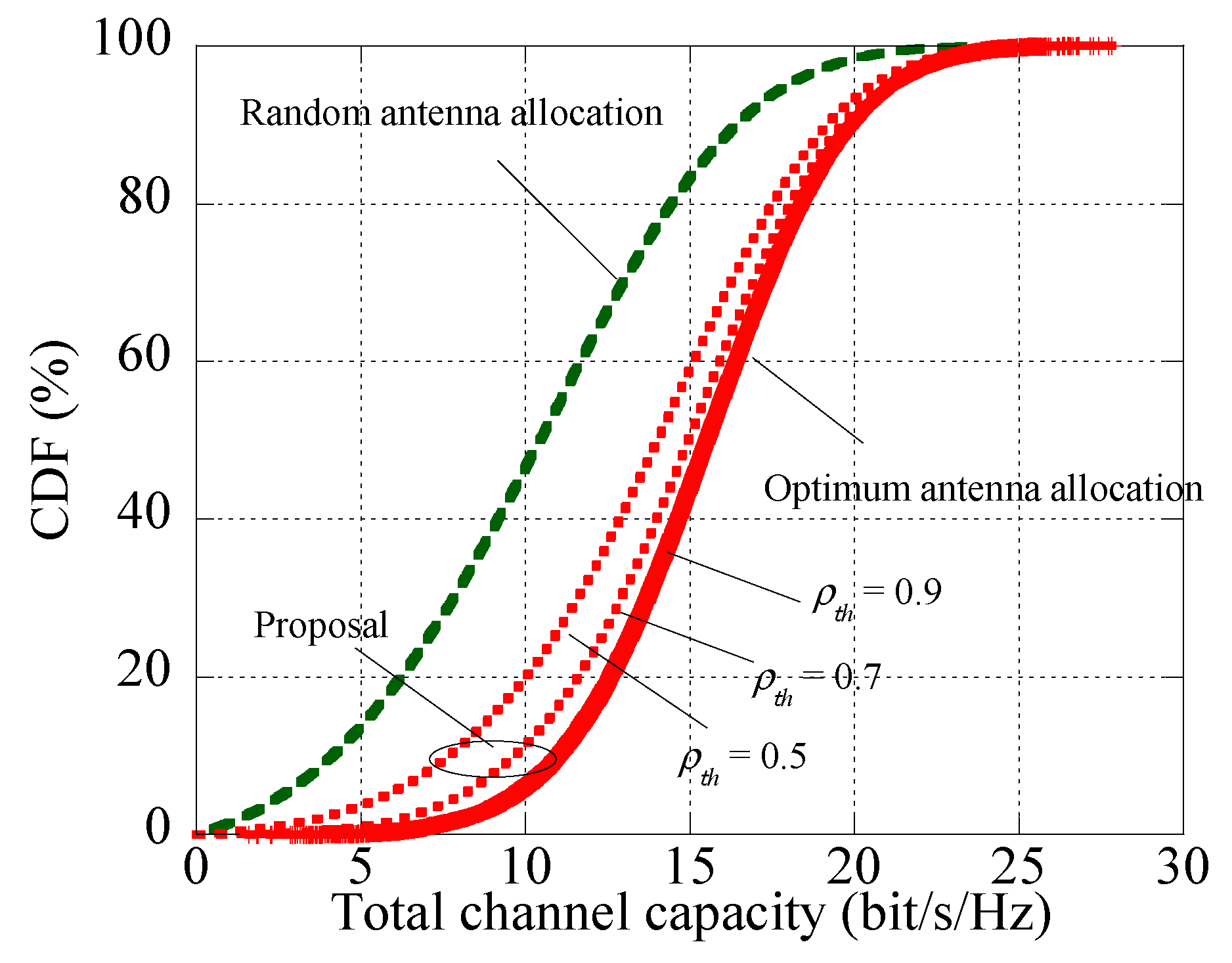
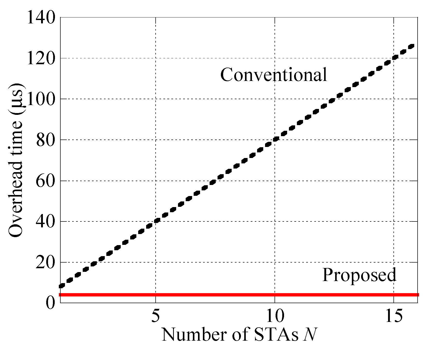
4.4. Analysis of Receiving Antenna Decision Method
5. Conclusions
Author Contributions
Funding
Conflicts of Interest
References
- Cisco Visual Networking Index: Global Mobile Traffic Forecast Update. Available online: https://www.cisco.com/c/en/us/solutions/collateral/service-provider/visual-networking-index-vni/mobile-white-paper-c11-520862.pdf (accessed on 26 July 2018).
- Traffic and Market Data Report. Available online: https://www.ericsson.com/res/docs/2014/ericsson-mobility-report-august-2014-interim.pdf (accessed on 26 July 2018).
- Andrews, J.G.; Buzzi, S.; Choi, W.; Hanly, S.V.; Lozano, A.; Soong, A.C.; Zhang, J.C. What will 5G be? IEEE J. Sel. Areas Commun. 2014, 6, 1065–1082. [Google Scholar] [CrossRef]
- Wang, C.X.; Haider, F.; Gao, X.; You, X.H.; Yang, Y.; Yuan, D.; Hepsaydir, E. Cellular architecture and key technologies for 5G wireless communication networks. IEEE Commun. Mag. 2014, 52, 122–130. [Google Scholar] [CrossRef] [Green Version]
- Nakamura, T. 3GPP TR 36.913—Requirements for further advancements for Evolved Universal Terrestrial Radio Access (EUTRA) LTE-Advanced. Available online: http://www.tech-invite.com/3m36/tinv-3gpp-36-913.html (accessed on 26 July 2018).
- IEEE Computer Society LAN MAN Standards Committee. Wireless LAN Medium Access Control (MAC) and Physical Layer (PHY) Specifications. In IEEE Std. 802.11ac-2013; IEEE: Piscataway, NJ, US, 2013. [Google Scholar]
- Larsson, E.L.; Edfors, O.; Tufvesson, F.; Marzetta, T.L. Massive MIMO for next generation wireless systems. IEEE Commun. Mag. 2014, 52, 185–195. [Google Scholar] [CrossRef]
- Ngo, H.Q.; Larsson, E.G.; Marzetta, T.L. Energy and spectral efficiency of very large multiuser MIMO systems. IEEE Trans. Commun. 2013, 61, 1436–1449. [Google Scholar]
- Spencer, Q.H.; Swindlehurst, A.L.; Haardt, M. Zero-forcing methods for downlink spatial multiplexing in multiuser MIMO channels. IEEE Trans. Signal Process. 2004, 52, 461–471. [Google Scholar] [CrossRef]
- Kudo, R.; Takatori, Y.; Nishimori, K.; Ohta, A.; Kubota, S. A new user measure in block diagonalization for multiuser MIMO systems. IEICE Trans. Commun. 2009, E92-B, 3206–3218. [Google Scholar] [CrossRef]
- Stankovic, V.; Haardt, M. Successive optimization Tomlinson-Harashima precoding (SO THP) for multi-user MIMO systems. In Proceedings of the IEEE International Conference on Acoustics, Speech, and Signal Processing, Philadelphia, PA, USA, 23 March 2005; Volume 3, pp. 1117–1120. [Google Scholar]
- Peel, C.; Hochwald, B.; Swindlehurst, L. A vector-perturbation technique for near-capacity multiantenna multiuser communication-part I: Channel inversion and regularization. IEEE Trans. Commun. 2005, 53, 195–202. [Google Scholar] [CrossRef]
- Codreanu, M.; Tolli, A.; Juntii, M.; Latva-aho, M. Joint design of Tx-Rx Beamforers in MIMO downlink channel. IEEE Trans. Signal Process. 2007, 55, 4639–4655. [Google Scholar] [CrossRef]
- Sadek, M.; Tarighat, A.; Sayed, A.H. Active antenna selection in multiuser MIMO communications. IEEE Trans. Signal Process. 2007, 55, 1498–1510. [Google Scholar] [CrossRef]
- Zhang, X.; Lv, Z.; Wang, W. Performance analysis of multiuser diversity in MIMO systems with antenna selection. IEEE Trans. Wirel. Commun. 2008, 7, 15–21. [Google Scholar] [CrossRef]
- Gore, D.A.; Paulraj, A.J. MIMO antenna subset selection with space-time coding. IEEE Trans. Signal Process. 2002, 50, 2580–2588. [Google Scholar] [CrossRef] [Green Version]
- Shen, Z.; Chen, R.; Andrews, J.G.; Heath, R.W.; Evans B, L. Low complexity user selection algorithms for multiuser MIMO systems with block diagonalization. IEEE Trans. Signal Process. 2006, 54, 3658–3663. [Google Scholar] [CrossRef]
- Ntontin, K.; Di Renzo, M.; Pérez-Neira, A.I.; Verikoukis, C. A low-complexity method for antenna selection in spatial modulation systems. IEEE Commun. Lett. 2013, 17, 2312–2315. [Google Scholar] [CrossRef]
- Zhang, H.; Li, Y.; Stolpman, V.; Van Waes, N. A reduced CSI feedback approach for precoded MIMO-OFDM systems. IEEE Trans. Wirel. Commun. 2007, 6. [Google Scholar] [CrossRef]
- Murakami, T.; Takatori, Y.; Mizoguchi, M.; Ujihara, K.; Maehara, F. Downlink multiuser MIMO-OFDM transmission using simple receive antenna selection. In Proceedings of the International Symposium on Antennas and Propagation, Ginowan, Japan, 24–28 October 2016; pp. 604–605. [Google Scholar]
- Murakami, T.; Takatori, Y.; Mizoguchi, M.; Maehara, F. Antenna decision method for downlink multiuser MIMO systems with receive antenna allocation. In Proceedings of the 2015 IEEE International Symposium on Antennas and Propagation & USNC/URSI National Radio Science Meeting, Vancouver, BC, Canada, 19–24 July 2015; pp. 304–305. [Google Scholar]
- Keysight Technologies. Available online: https://literature.cdn.keysight.com/litweb/pdf/5989-7819EN.pdf?id=1364807 (accessed on 26 July 2018).


| Parameter | Value |
|---|---|
| Center frequency | 5.18 GHz |
| Bandwidth (Subcarrier number) | 20 MHz (52) |
| Transmit power | 13 dBm |
| Number of AP antennas | 4 |
| Number of STA antennas | 2 |
| Transmit/Receiving antennas (Gain) | Dipole (2 dBi) |
© 2018 by the authors. Licensee MDPI, Basel, Switzerland. This article is an open access article distributed under the terms and conditions of the Creative Commons Attribution (CC BY) license (http://creativecommons.org/licenses/by/4.0/).
Share and Cite
Murakami, T.; Takatori, Y.; Maehara, F. A Receiving Antenna Allocation Scheme for Downlink MU-MIMO-OFDM Transmission. Electronics 2018, 7, 129. https://doi.org/10.3390/electronics7080129
Murakami T, Takatori Y, Maehara F. A Receiving Antenna Allocation Scheme for Downlink MU-MIMO-OFDM Transmission. Electronics. 2018; 7(8):129. https://doi.org/10.3390/electronics7080129
Chicago/Turabian StyleMurakami, Tomoki, Yasushi Takatori, and Fumiaki Maehara. 2018. "A Receiving Antenna Allocation Scheme for Downlink MU-MIMO-OFDM Transmission" Electronics 7, no. 8: 129. https://doi.org/10.3390/electronics7080129