Article

Impact Responses and Parameters Sensitivity Analysis of Electric Wheelchairs

School of Automation, Beijing University of Posts and Telecommunications, 10 Xitucheng Road, Haidian District, Beijing 100876, China
*
Author to whom correspondence should be addressed.
Electronics 2018, 7(6), 87; https://doi.org/10.3390/electronics7060087
Submission received: 8 May 2018 / Revised: 28 May 2018 / Accepted: 1 June 2018 / Published: 3 June 2018

Abstract

:

Featured Application

This work is specifically applied to wheelchairs.

Abstract

The shock and vibration of electric wheelchairs undergoing road irregularities is inevitable. The road excitation causes the uneven magnetic gap of the motor, and the harmful vibration decreases the recovery rate of rehabilitation patients. To effectively suppress the shock and vibration, this paper introduces the DA (dynamic absorber) to the electric wheelchair. Firstly, a vibration model of the human-wheelchair system with the DA was created. The models of the road excitation for wheelchairs going up a step and going down a step were proposed, respectively. To reasonably evaluate the impact level of the human-wheelchair system undergoing the step–road transition, evaluation indexes were given. Moreover, the created vibration model and the road–step model were validated via tests. Then, to reveal the vibration suppression performance of the DA, the impact responses and the amplitude frequency characteristics were numerically simulated and compared. Finally, a sensitivity analysis of the impact responses to the tire static radius r and the characteristic parameters was carried out. The results show that the DA can effectively suppress the shock and vibration of the human-wheelchair system. Moreover, for the electric wheelchair going up a step and going down a step, there are some differences in the vibration behaviors.

1. Introduction

Wheelchairs are medical devices [1]. They are widely used in hospitals, rehabilitation institutions, and endowment institutions [2]. With the progress of society, rehabilitation wheelchairs have developed from simple travel tools to important means of enabling the elderly and the disabled to exercise, take care of themselves, and participate in social activities [3,4,5]. They have played an important role in integrating the elderly and the disabled back into society.
Wheelchairs can be mainly divided into three categories according to their sophistication: manual wheelchairs [6], electric wheelchairs [7], and intelligent wheelchairs [8]. Manual wheelchairs are the most common rehabilitation accessories. They have been widely used by the elderly and the disabled. Manual wheelchairs are affordable and more suitable for ordinary families. Electric wheelchairs are based on the traditional manual wheelchairs. They are equipped with a high-performance power driving device, batteries, and an electric control system [9]. A traditional wheelchair must rely on manpower. If no one takes care of the user, he/she will have to push the wheel himself. For an electric wheelchair, so long as the batteries are fully charged, there is no need for the family members to accompany the user all of the time. Intelligent wheelchairs are an important application platform of robot technologies. They combine many technologies in the robot field, such as motion control, machine vision, pattern recognition, and human–machine interaction [10,11]. The price of intelligent wheelchairs is very high. It is difficult for ordinary families to afford them.
In recent years, the enormous demand for wheelchairs has led to higher performance requirements [12]. How to effectively reduce the shock and vibration of electric wheelchairs has aroused a growing public attention [13,14,15]. When an electric wheelchair undergoes road irregularities, the shock and vibration of the human body and the wheelchair body are inevitable. The adverse effects of the shock and vibration caused by the road excitation mainly include four aspects. (1) The shock and vibration transmitted to the human body decrease the recovery rate of the patients. (2) The road excitation causes the uneven magnetic gap of the motor, resulting in the further deterioration of the vibration. (3) The intense shock causes a shorter working life of the wheelchair accessories, which include for instance, the mechanical parts, the motor, and the control hardware system. (4) The excessive vibration reduces the tire grounding safety.
Various standards have been developed around the world to evaluate the performances of wheelchairs. The British standard 12183-2009 provides the requirements and the test methods of manual wheelchairs [16]. America instituted the standard ANSI/RESNA WC-1a-2009 for wheelchairs [17]. China instituted the standard GB/T 13800-2009 [18]. This standard is applicable for manual wheelchairs and electric wheelchairs. Generally speaking, the vibration acceleration of the human body is used to evaluate the ride comfort of wheelchairs; the vibration acceleration of the wheelchair body is used to evaluate the operational reliability of the wheelchair accessories. Moreover, the tire dynamic deflection fd or the tire contact force is often used to characterize the tire grounding safety [19].
To effectively reduce the shock and vibration of wheelchairs, scholars from various countries have studied the issue and made some achievements. Some scholars focused on the investigation of the cushion system of wheelchairs. For example, Hillman et al. investigated the hysteresis and impact damping of cushions for wheelchairs [20]. Wang et al. studied the comfort of cushions for electric wheelchairs [21]. Brienza et al. researched the influences of the wheelchair cushion type on tissue deformation [22]. Some scholars paid attention to the dynamic modeling of wheelchairs. For example, Brown et al. created a model of wheelchair-users undergoing vibrations [23]. Leary et al. proposed a mathematical model of wheelchair biomechanics [24]. Chen et al. established a model of an electric wheelchair and identified its system parameters [25]. Salipur et al. developed a rear impact model of an adult manual transit wheelchair with a seated occupant [26]. Ceravolo et al. created a predictive control model of an autonomous wheelchair [27]. These models provide useful references and tools for analyzing the comfort and vibration of wheelchairs. In addition, there are also some scholars who devoted themselves to the vibration characteristics research of wheelchairs. Dziechciowski et al. analyzed the vibration transmitted to the human body during the patient’s ride in a wheelchair [28]. Hikmawan et al. analyzed the comfort of electric wheelchairs using a half-car model [29]. Miyawaki et al. studied the whole-body vibration of passengers sitting on wheelchairs loaded onto a lifter [30]. Su et al. designed a magnetic suspension vibrator for electric wheelchairs [31]. Ababou et al. developed a test bench for the analysis of harmful vibrations to wheelchair users [32]. Hischke et al. analyzed the influence of the rear wheel suspension on the tilt-in-space wheelchair shock and vibration attenuation [33]. These studies provide useful references for attenuating the shock and vibration of wheelchairs. However, there are few studies on the comprehensive performance of wheelchairs undergoing a step.
The dynamic absorber (DA) is a vibration-reducing device that is connected to the vibration system by elastic and damping elements. It occupies a small space, and provides a cheap and effective way to attenuate the shock and vibration of various vibration systems [34]. For example, Orečný et al. introduced the DA to a working machine seat, and showed that the DA can effectively suppress the seat vibration [35]. However, there have been no related research reports on the use of dynamic absorbers in wheelchairs. To effectively suppress the shock and vibration, this paper introduces the DA to the electric wheelchair. In Section 2, to theoretically prove the vibration isolation effect of the DA in wheelchairs, a vibration model of the human-wheelchair system with the DA was created. In Section 3, the models of the road excitation for wheelchairs going up a step and going down a step were proposed, respectively. In Section 4, to effectively evaluate the impact level of the human-wheelchair system undergoing the step road, the evaluation indexes were given. In Section 5, the created vibration model and the road step model were validated by test. In Section 6, to reveal the vibration suppression performance of the DA, the impact responses were numerically simulated and compared. In Section 7, the influences of the tire static radius r on the vibration behaviors of the human-wheelchair system were analyzed. In Section 8, the influences of the characteristic parameters on the vibration behaviors were revealed.

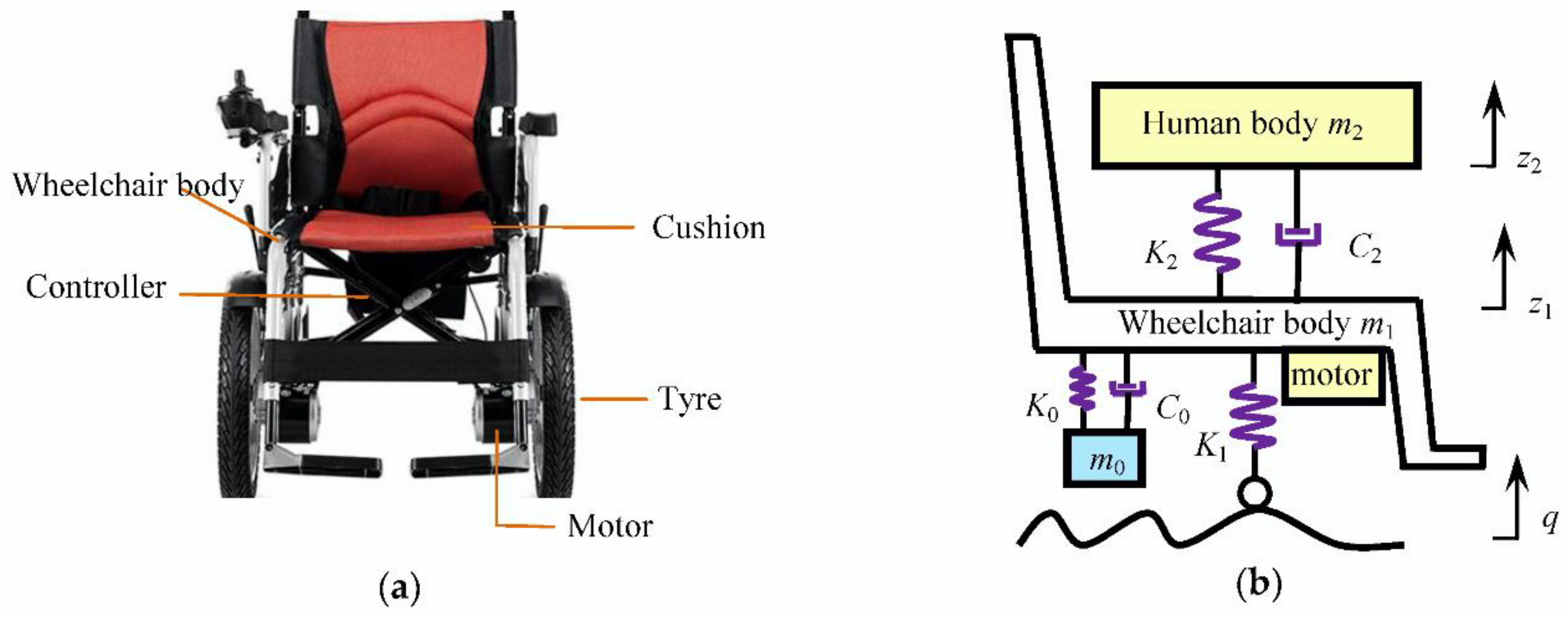
2. Modeling of the Human-Wheelchair System with DA

A commercially available electric wheelchair is shown in Figure 1a. According to the electric wheelchair, a simplified vibration model of the human-wheelchair system with the DA was created, as shown in Figure 1b where the motor is fixed on the wheelchair body; m2, m1, and m0 are the human body mass, the wheelchair body mass (including the motor mass), and the DA mass, respectively; C2 and C0 are the damping coefficients of the cushion and the DA, respectively; K2, K1, and K0 are stiffness coefficients of the cushion, the tire system, and the DA, respectively; z2, z1, and z0 are the corresponding displacements; and q is the road excitation.
The differential equations of the vibration model can be expressed as:
{ m 2 z ¨ 2 + C 2 ( z ˙ 2 z ˙ 1 ) + K 2 ( z 2 z 1 ) = 0 m 0 z ¨ 0 + C 0 ( z ˙ 0 z ˙ 1 ) + K 0 ( z 0 z 1 ) = 0 m 1 z ¨ 1 + C 2 ( z ˙ 1 z ˙ 2 ) + K 2 ( z 1 z 2 ) + C 0 ( z ˙ 1 z ˙ 0 ) + K 0 ( z 1 z 0 ) + K 1 ( z 1 q ) = 0 .
The natural frequencies, the damping ratios, and other ratio parameters have important guiding significances for the wheelchair design. The characteristic parameters are adopted as follows:
ω 2 = K 2 m 2 ,   ω 1 = K 1 m 1 ,   ω 0 = K 0 m 0 ,   ξ 2 = C 2 2 m 2 K 2 ,   ξ 0 = C 0 2 m 0 K 0 ,   r 0 = m 0 m 1 ,   r 2 = m 2 m 1
where, ω0, ω1, and ω2 are the natural circular frequencies of the DA, the wheelchair body, and the human body, respectively; ξ0 and ξ2 are the damping ratios of the DA system and the cushion system, respectively; r0 is the mass ratio of the DA mass to the wheelchair body mass; and r2 is the mass ratio of the human body mass to the wheelchair body mass.
Based on the adopted characteristic parameters, Equation (1) can be rewritten as:
{ m 2 z ¨ 2 + 2 m 2 ξ 2 ω 2 ( z ˙ 2 z ˙ 1 ) + m 2 ω 2 2 ( z 2 z 1 ) = 0 m 0 z ¨ 0 + 2 m 0 ξ 0 ω 0 ( z ˙ 0 z ˙ 1 ) + m 0 ω 0 2 ( z 0 z 1 ) = 0 m 1 z ¨ 1 + 2 m 2 ξ 2 ω 2 ( z ˙ 1 z ˙ 2 ) + m 2 ω 2 2 ( z 1 z 2 ) + 2 m 0 ξ 0 ω 0 ( z ˙ 1 z ˙ 0 ) + m 0 ω 0 2 ( z 1 z 0 ) + m 1 ω 1 2 ( z 1 q ) = 0 .
Equation (2) can be further expressed as:
{ z ¨ 2 + 2 ξ 2 ω 2 ( z ˙ 2 z ˙ 1 ) + ω 2 2 ( z 2 z 1 ) = 0 z ¨ 0 + 2 ξ 0 ω 0 ( z ˙ 0 z ˙ 1 ) + ω 0 2 ( z 0 z 1 ) = 0 z ¨ 1 + 2 r 2 ξ 2 ω 2 ( z ˙ 1 z ˙ 2 ) + r 2 ω 2 2 ( z 1 z 2 ) + 2 r 0 ξ 0 ω 0 ( z ˙ 1 z ˙ 0 ) + r 0 ω 0 2 ( z 1 z 0 ) + ω 1 2 ( z 1 q ) = 0 .

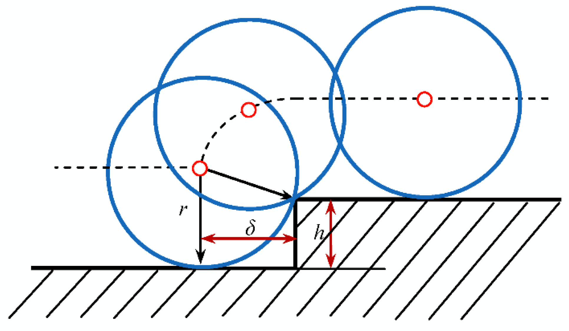
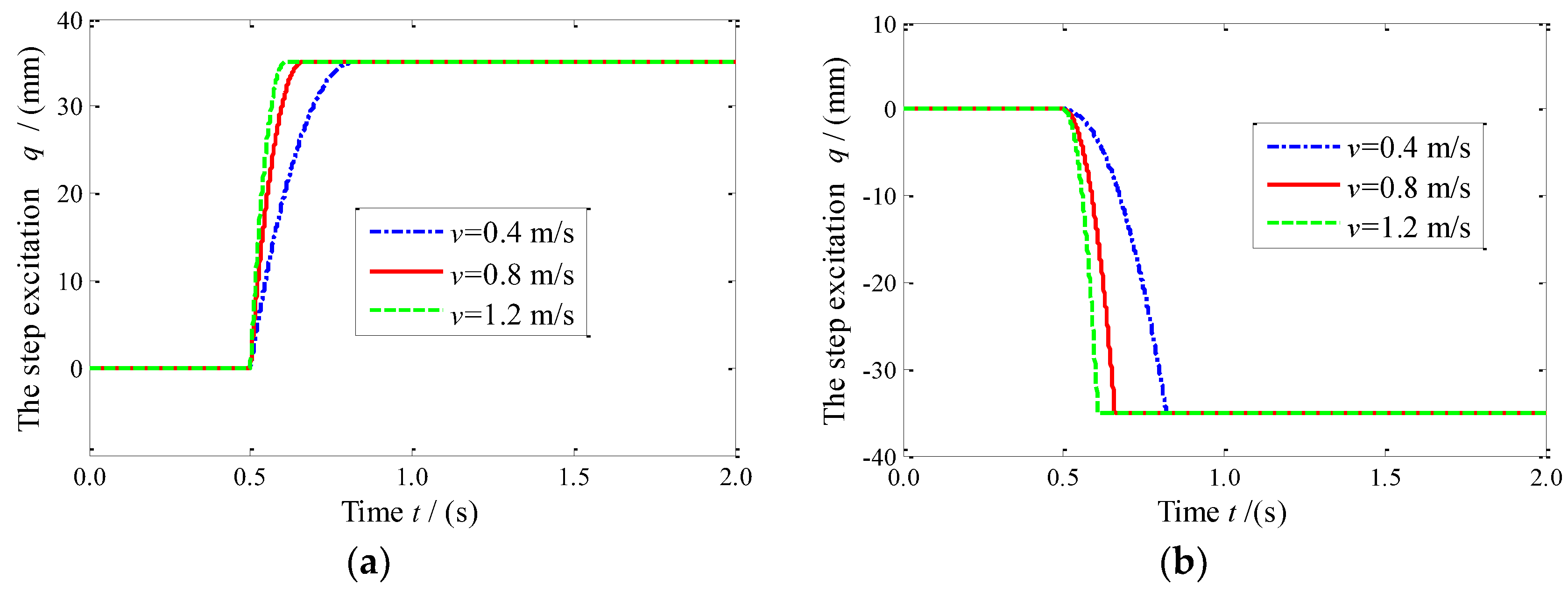
3. Modeling of the Step Road Excitation

When a wheelchair goes up a step or goes down a step, the displacement excitation is not exactly the same as the step shape. The tire has a correction to the step–road surface. Figure 2 depicts the rolling condition of the tire passing the step without leaving the road surface. In Figure 2, the dotted line is the trajectory of the tire center; r is the static radius of the tire; h is the height of the step; and δ is the horizontal distance of the tire center to the step.
From Figure 2, we obtain the following:
δ 2 + ( r h ) 2 = r 2 .
Based on Equation (4), we produce:
δ = 2 r h h 2 .
For a wheelchair going up the step, the step–road excitation can be expressed as:
q = { h + r 2 ( δ v t ) 2 r t [ 0 , δ v ] h   t ( δ v , + ] ,
where t is time, and v is the running speed of wheelchairs.
For a wheelchair going down the step, the step road excitation can be expressed as:
q = { r 2 v 2 t 2 r t [ 0 , δ v ] h   t ( δ v , + ] .
For example, r = 250 mm for a wheelchair, h = 35 mm, and v = 0.4, 0.8, and 1.2 m/s. Figure 3a,b depicts the time histories of the step excitation q for the wheelchair going up the step and going down the step, respectively. It can be seen that the greater the running speed v, the more sharply the excitation changes.

4. Evaluation Indexes

In order to evaluate the impact level of the human-wheelchair system undergoing the step road, the unweighted vibration dose values (VDV) of the wheelchair body and the human body are adopted, respectively. They are the cumulative values of the corresponding acceleration values for a period of time. According to the ISO2631 standard, the sensitivity of the human body to different vibration frequencies is different. When evaluating the impact of the vibration on the human health, the vibration signals need to be weighted on the basis of the ISO2631 standard. This study mainly focuses on the impact strength and analyzes the vibration isolation effect of the DA. Thus, the acceleration signals are not weighted.
Based on the vibration model, the vibration dose value VDV1 of the wheelchair body acceleration z ¨ 1 = a1 can be expressed as:
VDV 1 = [ 0 T a 1 4 ( t ) d t ] 1 4 .
where T is the length of time from the tire starting to contact the step to the vibration disappearing.
The vibration dose value VDV2 of the human body acceleration z ¨ 2 = a2 can be expressed as:
VDV 2 = [ 0 T a 2 4 ( t ) d t ] 1 4 .
The boundary condition of the tires off the ground can be expressed as:
f d f d 0 0 .
For the human-wheelchair system with the DA and without the DA, the calculation formula of the tire static deflection fd0 are as follows, respectively:
f d 0 = { m 0 + m 1 + m 2 K 1 , with   DA m 1 + m 2 K 1 , without   DA ,
The ratio p of the length of time for f d f d 0 0 to T is adopted as the evaluation index of the running safety:
p = N Δ t T ,
where N is the number of the points satisfying Equation (10); and Δ t is the simulation step.
When the wheelchair undergoes a step, during the time from the tire starting to contact the step to the vibration disappearing, the condition of the tire off the ground should be avoided. If the tire does not contact the ground, the maneuverability of the wheelchair will be reduced. Thus, the smaller of the ratio p, the better the tire grounding safety.
In order to further investigate the vibration attenuation effect of the DA, the vibration transfer characteristics need to be analyzed. According to Equation (3), the transfer functions of the wheelchair body acceleration z ¨ 1 , the human body acceleration z ¨ 2 , and the tire dynamic deflection fd = z1q to the road excitation velocity q ˙ can be respectively expressed as:
H 1 = H z ¨ 1 ~ q ˙ = ω 1 2 s 5 + ( 2 ξ 0 ω 0 + 2 ξ 2 ω 2 ) ω 1 2 s 4 + ( ω 0 2 + 4 ξ 0 ξ 2 ω 0 ω 2 + ω 2 2 ) ω 1 2 s 3 + L X s 2 + ω 0 2 ω 1 2 ω 2 2 s s 6 + L 5 s 5 + L 4 s 4 + L 3 s 3 + L 2 s 2 + L 1 s + L 0 ,
H 2 = H z ¨ 2 ~ q ˙ = 2 ξ 2 ω 1 2 ω 2 s 4 + ( ω 2 2 + 4 ξ 0 ξ 2 ω 0 ω 2 ) ω 1 2 s 3 + L X s 2 + ω 0 2 ω 1 2 ω 2 2 s s 6 + L 5 s 5 + L 4 s 4 + L 3 s 3 + L 2 s 2 + L 1 s + L 0 ,
H 3 = H f d ~ q ˙ = ω 1 2 s 4 + 2 ( ξ 0 ω 0 + ξ 2 ω 2 ) ω 1 2 s 3 + ( ω 0 2 + 4 ξ 0 ξ 2 ω 0 ω 2 + ω 2 2 ) ω 1 2 s 2 + L X s + ω 0 2 ω 1 2 ω 2 2 ( s 6 + L 5 s 5 + L 4 s 4 + L 3 s 3 + L 2 s 2 + L 1 s + L 0 ) s 1 s ,
where s is the Laplace operator:
  • L X = 2 ( ξ 2 ω 0 2 ω 2 + ξ 0 ω 0 ω 2 2 ) ω 1 2 ,
  • L 5 = 2 ξ 0 ω 0 + 2 ξ 2 ω 2 + 2 ξ 0 ω 0 r 0 + 2 ξ 2 ω 2 r 2 ,
  • L 4 = ω 0 2 + ω 1 2 + ω 2 2 + r 0 ω 0 2 + r 2 ω 2 2 + 4 ξ 0 ξ 2 ω 0 ω 2 + 4 r 0 ξ 0 ξ 2 ω 0 ω 2 + 4 r 2 ξ 0 ξ 2 ω 0 ω 2 ,
  • L 3 = 2 ξ 0 ω 0 ω 1 2 + 2 ξ 0 ω 0 ω 2 2 + 2 ξ 2 ω 0 2 ω 2 + 2 ξ 2 ω 1 2 ω 2 + 2 r 0 ξ 0 ω 0 ω 2 2 + 2 r 0 ξ 2 ω 0 2 ω 2 + 2 r 2 ξ 0 ω 0 ω 2 2 + 2 r 2 ξ 2 ω 0 2 ω 2 ,
  • L 2 = ω 0 2 ω 1 2 + ω 0 2 ω 2 2 + ω 1 2 ω 2 2 + r 0 ω 0 2 ω 2 2 + r 2 ω 0 2 ω 2 2 + 4 ξ 0 ξ 2 ω 0 ω 1 2 ω 2 ,
  • L 1 = 2 ξ 0 ω 0 ω 1 2 ω 2 2 + 2 ξ 2 ω 0 2 ω 1 2 ω 2 , L 0 = ω 0 2 ω 1 2 ω 2 2 .

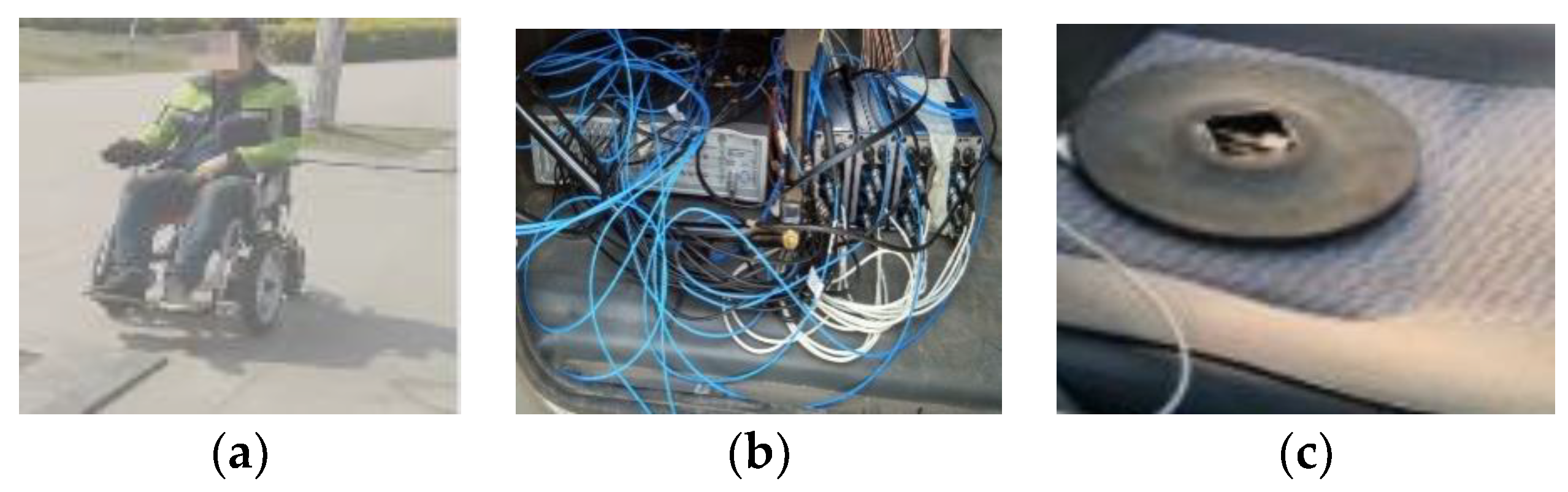
5. Test Verification

To verify the effectiveness of the created vibration model and the step road model, the test verification should be carried out. If the DA system is directly mounted on electric wheelchairs, there will be some risks. For example, the mismatched DA may aggravate the vibration of wheelchairs and do harm to human bodies. Therefore, this study carried out the pulse test by using an electric wheelchair manufactured by Bo Yu Electric Vehicle Co., Ltd. (Yongkang, China). This wheelchair is not equipped with the DA system. The values of the parameters for the human-wheelchair system are shown in Table 1.
The pulse test was conducted in the test field, as shown in Figure 4a. The height of the step is h = 35 mm. The test condition is v = 0.2~0.8 m/s. The test equipment is LMS Test.Lab (LMS Company, Leuven, Belgium), as shown in Figure 4b. The sample frequency was set as 512 Hz. Before the test, a Lance LC0173 acceleration sensor (Lance Techonogies Inc., Copley, OH, America) was installed on the cushion of the test wheelchair, as shown in Figure 4c.
The tested values of VDV2 were calculated based on the measured human body acceleration signals. Moreover, according to the parameters in Table 1, the simulated human body acceleration signals were obtained using Equation (1) with m0 = 0. Then, the simulated values of VDV2 were calculated. Table 2 and Table 3 give the comparisons of the calculated results. From Table 2 and Table 3, it can be seen that the relative deviations of the simulated VDV2 and the tested VDV2 are less than 10%. The results show that the created vibration model for the wheelchair without the DA is workable, and the step road model is effective.

6. Comparison Analysis of Performances

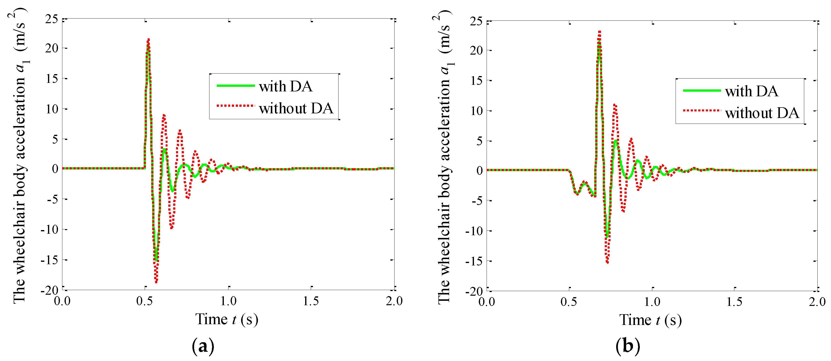
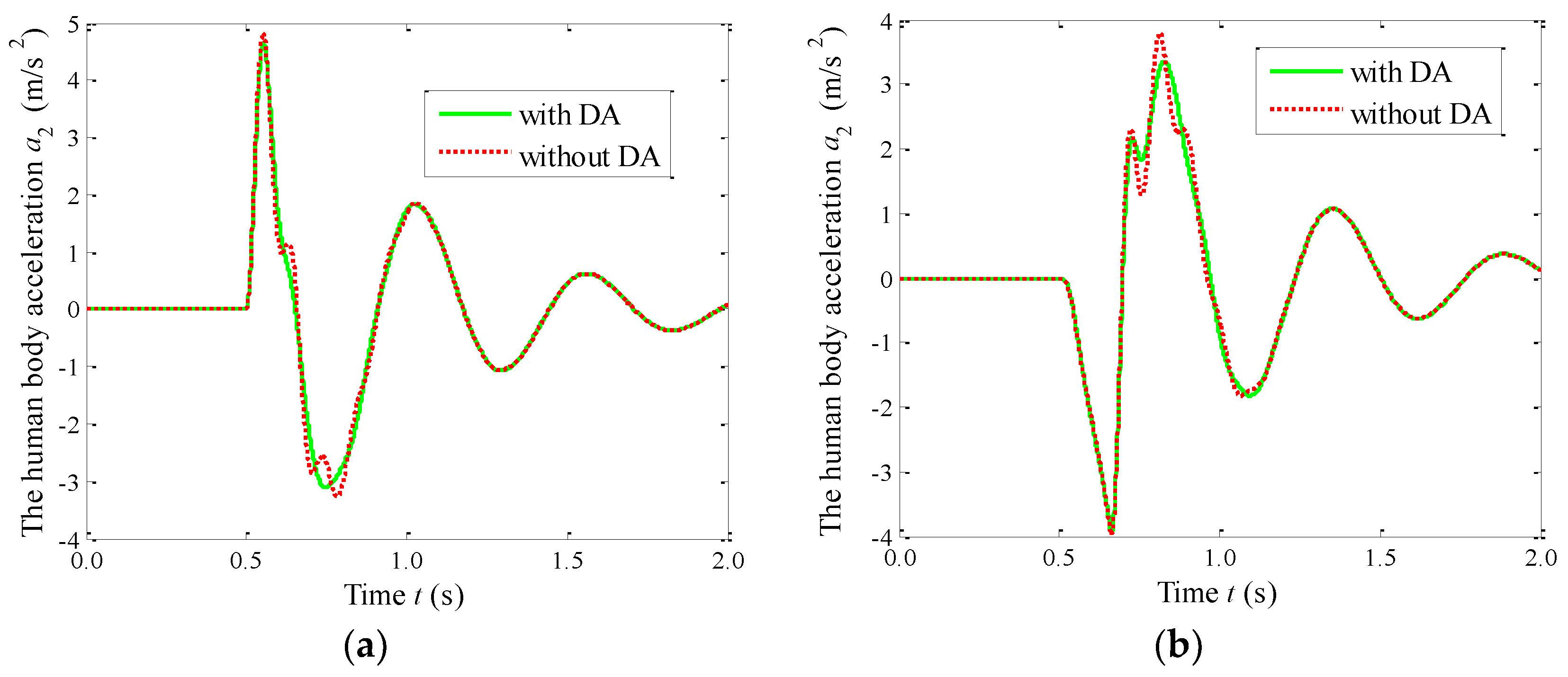
6.1. The Time Domain Responses

To reveal the vibration suppression performance of the DA, the impact responses were numerically simulated. The simulation condition is set as: h = 35 mm, v = 0.2~1.2 m/s. The simulation step is set as Δ t = 0.001 s. Table 4 gives the values of the parameters for the human-wheelchair system. Based on the selection method of the DA [34,35], the DA mass m0 was selected as the 10% of the wheelchair body mass m1. To make ω0 = ω1, the DA stiffness K0 was also selected as the 10% of the tire stiffness K1. The damping ratio ξ0 was selected as 0.25; thus, C0 = 78 Ns/m. Figure 5 provides a comparison of the vibration behaviors of the human-wheelchair system with the DA and without the DA undergoing the step.
As shown in Figure 5a, VDV1 increases linearly with the increase of the running speed v. The curves of VDV1 versus v are almost the same for the wheelchair going up and going down the step. Compared with the wheelchair without the DA, the VDV1 of the wheelchair with the DA is reduced by 11.2%. Figure 5b shows that VDV2 increases nonlinearly with the increase of the running speed v. The VDV2 values of the wheelchair going down the step are slightly larger than those of the wheelchair going up the step. Compared with the wheelchair without the DA, the VDV2 of the wheelchair with the DA is reduced by 11.3%. As shown in Figure 5c, p increases rapidly with the increase of the running speed v at the beginning. When v >0.8 m/s, p hardly increases. From v = 0.0 m/s to v = 0.4 m/s, the DA system has little effect on p. When v = 0.8 m/s, the improvement of p is up to 16.7%. In addition, the curves of p versus v are almost the same from v = 0.0 m/s to v = 0.4 m/s for the wheelchair going up and going down the step. When v >0.4 m/s, the p value of the wheelchair going down the step is obviously larger than that of the wheelchair going up the step.
The comparison results show that the three evaluation indexes are all improved by using the DA. This proves that the DA can effectively improve the vibration isolation performance of the wheelchairs. In addition, when the wheelchair goes up the step and goes down the step, the differences for VDV1 and VDV2 are relatively smaller, but the differences for p are relatively larger, with a maximum difference of more than 10%.
To more clearly show the effects of the DA for the wheelchair undergoing the step, Figure 6, Figure 7 and Figure 8 give a comparison of the time histories of the vibration responses. As shown in Figure 6a,b, compared with the wheelchair without the DA, the wheelchair with the DA can rapidly attenuate the road impact. When the wheelchair goes up the step, the maximum acceleration of the wheelchair body appears during the process of the wheelchair going up the step. When the wheelchair goes down the step, the maximum acceleration of the wheelchair body appears after passing the step. Figure 7a,b shows that the DA can only significantly reduce the second maximum peak of the human body acceleration. The maximum acceleration of the human body for the wheelchair going up the step is 26.6% larger than that for the wheelchair going down the step. Figure 8a,b indicates that the DA can effectively suppress fd starting from the second peak. In the process of the wheelchair going up the step, the maximum value of fd is reduced by 33.4% by using the DA. The maximum value of fd cannot be obviously improved in the process of the wheelchair going down the step.

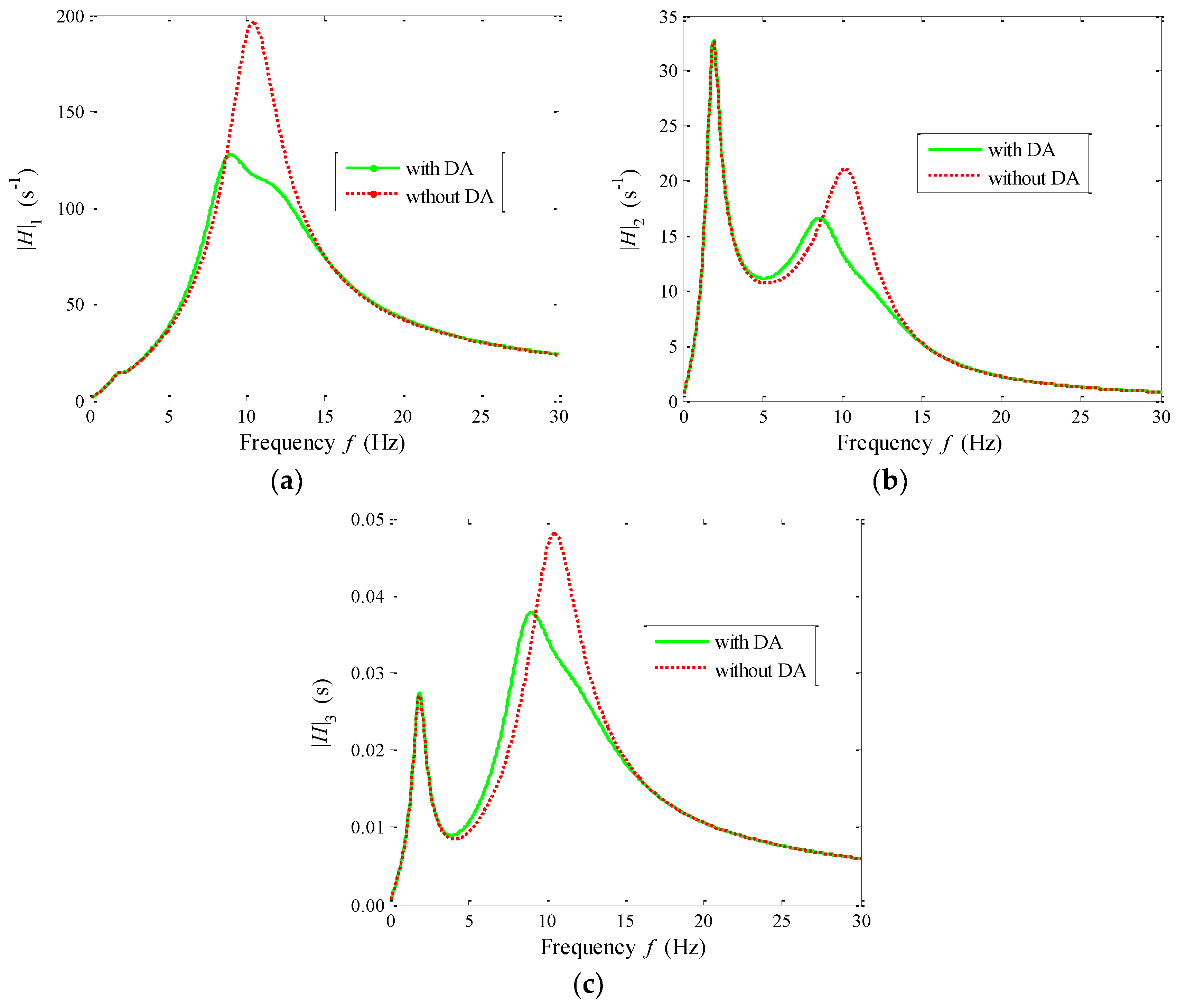
6.2. The Frequency Responses

Only analyzing the time domain responses is not enough to fully reveal the differences of the system with the DA and without the DA. The amplitude frequency characteristics of the system should be analyzed. In this section, based on the parameters in Table 1, the curves of |H1|, |H2|, and |H3| versus the excitation frequency f were plotted, as shown in Figure 9.
Figure 9a shows that the amplitude of |H1| for the system with the DA is 38.5% smaller than that for the system without the DA in the resonant region of the wheelchair body. The result proves that the DA can effectively suppress the vibration of the wheelchair body. Figure 9b depicts that by using the DA, the amplitude of |H2| can be reduced about 23.5% around the second resonance peak. The result proves that although the DA cannot suppress the vibration of the human body around the first resonance peak, it can obviously improve the vibration isolation performance of the wheelchair system around the second resonance peak. From Figure 9c, it can be seen that the maximum amplitude of |H3| appears in the resonant region of the wheelchair body; the amplitude is reduced by more than 20.0% in this region. To sum up, the DA can significantly reduce the amplitudes of |H1|, |H2|, and |H3| in the resonant region of the wheelchair body. Moreover, the DA does not lead to the vibration deterioration in the resonant region of the human body. The DA has a favorable effect that reduces the tire dynamic deflection and attenuates the vibration of the human body and the wheelchair body.

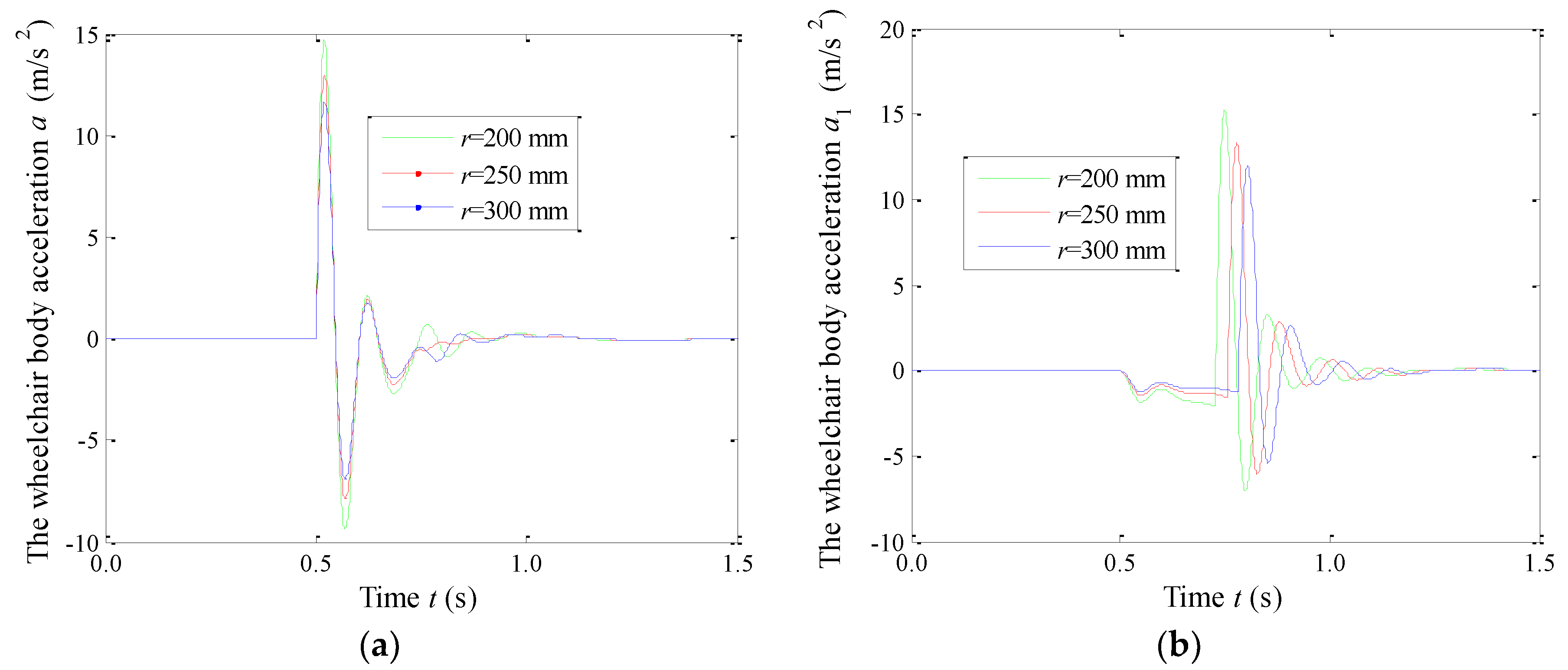
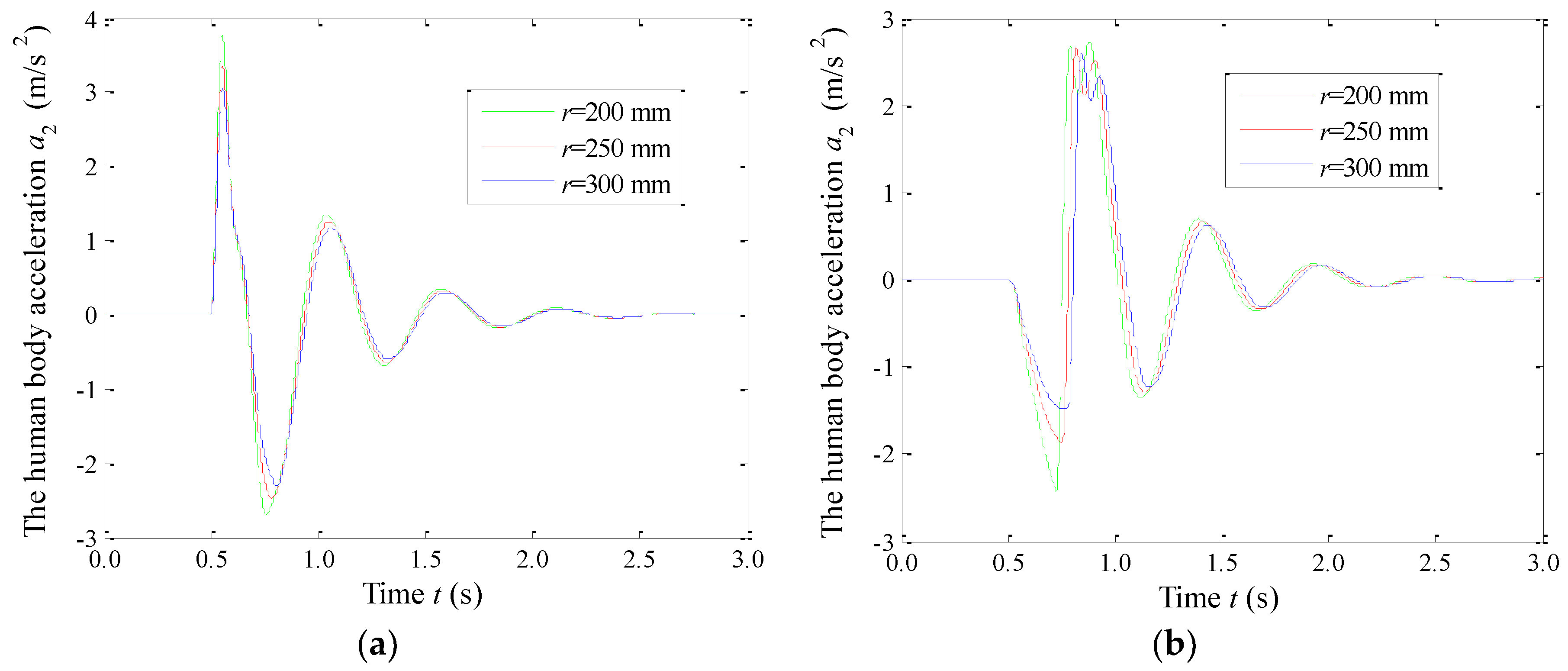
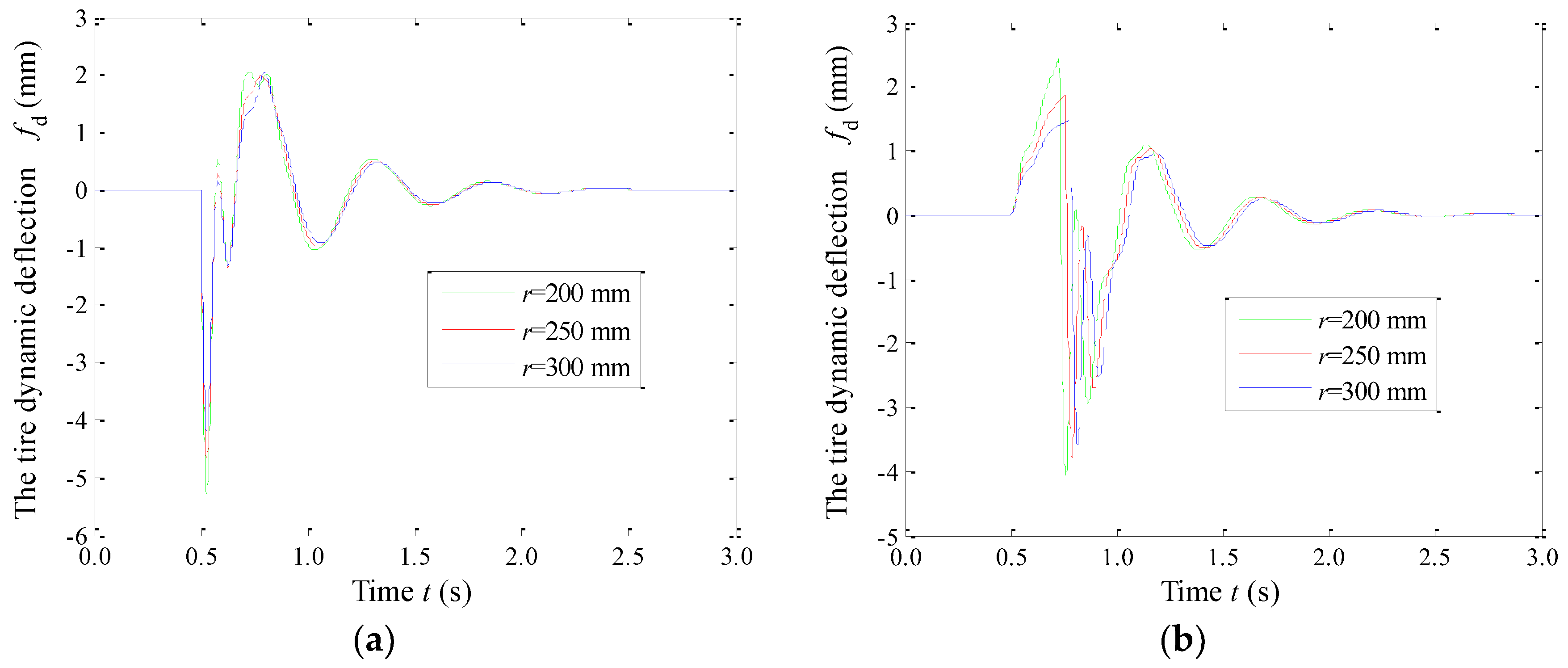
7. Influences of the Tire Static Radius r on the Vibration Behaviors

To reveal the influences of the tire static radius r on the vibration behaviors, the impact responses were numerically simulated for r = 200 mm, 250 mm, and 300 mm, respectively. The used parameters of the human-wheelchair system with the DA are in Table 4. The simulation condition is set as: h = 35 mm, v = 0.5 m/s. The simulation step is set as Δ t = 0.001 s. The calculated results of the vibration responses were given in Table 5. The comparisons of the time histories of the wheelchair body acceleration a1, the human body acceleration a2, and the tire dynamic deflection fd at different values of r are shown in Figure 10, Figure 11 and Figure 12, respectively
Table 5 shows that with the increase of the tire static radius r, the vibration responses VDV1, VDV2, and p decrease. Thus, increasing r contributes to the attenuation of the pavement impact. Figure 10a,b shows that increasing r can effectively suppress the vibration peaks of the wheelchair body acceleration a1. Interestingly, with the increase of r, the response curve of a1 clearly moves to the right for the wheelchair going down the step. Figure 11a,b illustrates that increasing r helps to reduce the vibration of the human body. Similarly, with the increase of r, the response curve of a2 also moves to the right for the wheelchair going down the step. Figure 12a depicts that increasing r cannot obviously reduce the maximum value of fd for the wheelchair going up the step. Figure 12b shows that increasing r can effectively reduce the maximum value of fd for the wheelchair going down the step. Moreover, the response curve of fd also shifts to the right.

8. Sensitivity Analysis of the Impact Responses to the Characteristic Parameters

To reveal the influence laws of the characteristic parameters r2, r0, ξ2, ξ0, f1, f2, and f0 on the vibration behaviors, VDV1, VDV2, and p were calculated. Where, f0 = ω0/2π, f1 = ω1/2π, and f2 = ω2/2π. When analyzing the influence of one of the seven characteristic parameters, the baseline value is increased by 100% or decreased by 50%. The values of the characteristic parameters are provided in Table 6. To plot the curves of VDV1, VDV2, and p versus a certain characteristic parameter in one diagram, VDV1, VDV2, and p are normalized by y 1 = VDV 1 / | VDV 1 | b , y 2 = VDV 2 / | VDV 2 | b , and y 3 = p / | p | b , respectively, where, the subscript “b” represents “baseline”.

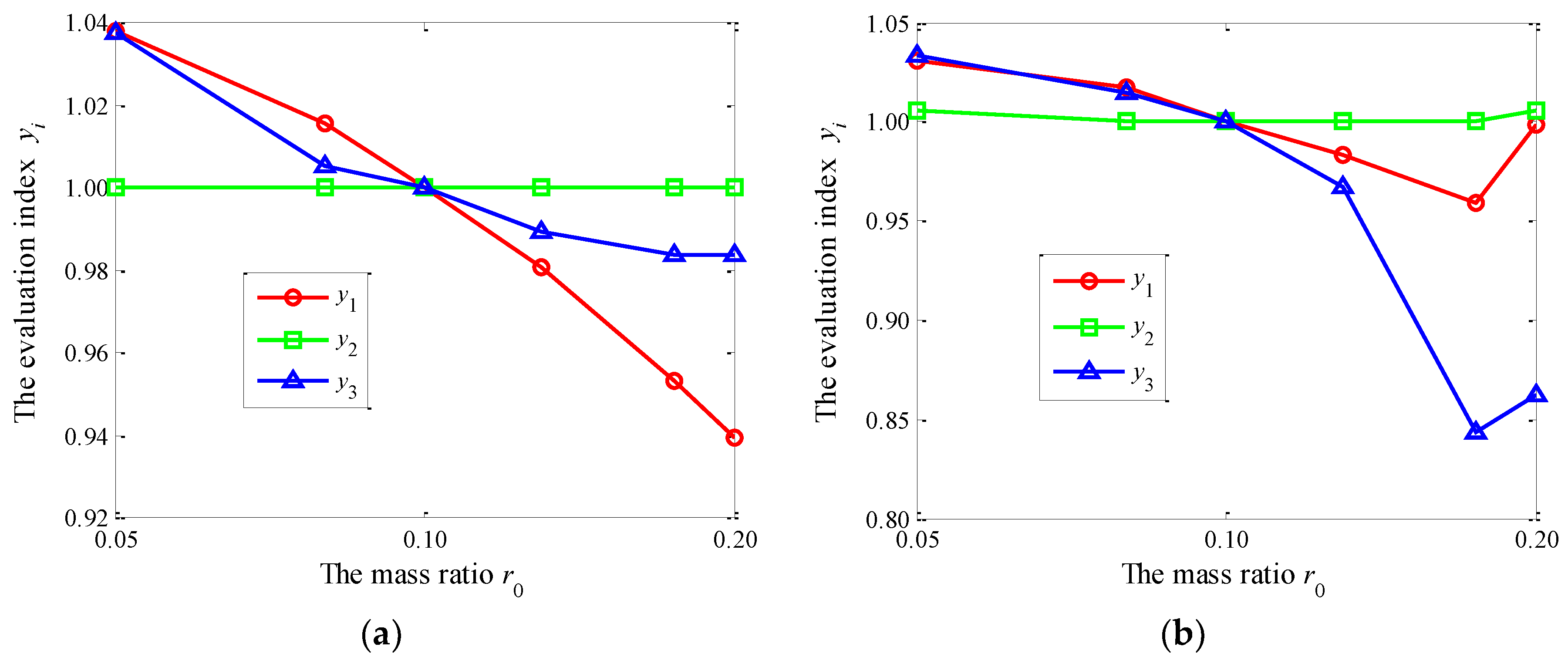
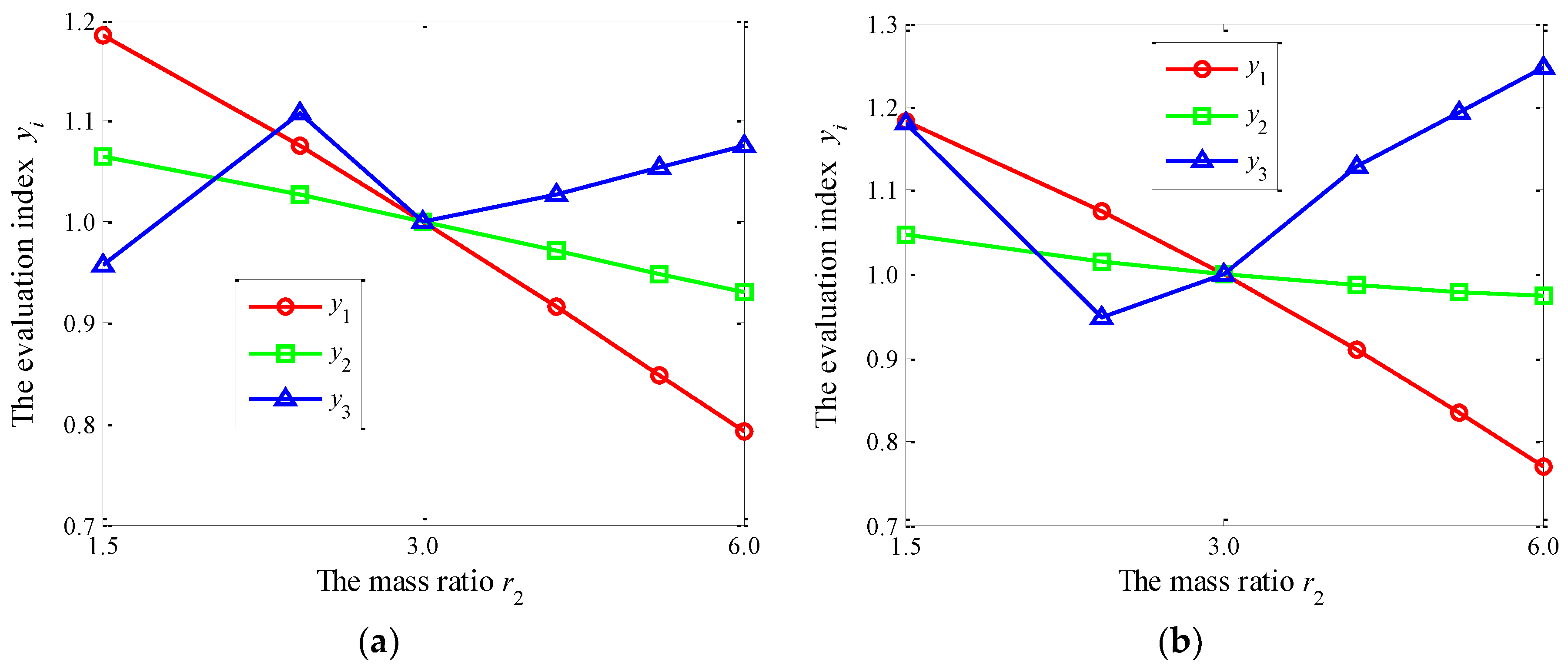
8.1. Influences of the Mass Ratios r0 and r2

Figure 13 and Figure 14 show the curves of the evaluation indexes y1, y2, and y3 versus the mass ratios r0 and r2, respectively. As shown in Figure 13, the effect of r0 on y2 is very small. With the increase of r0, both y1 and y3 decrease. For the wheelchair going up the step, r0 has a greater influence on y1 than on y3. For the wheelchair going down the step, r0 has a greater influence on y3 than on y1. Therefore, it is difficult to effectively suppress the vibration acceleration of the human body by changing r0. From Figure 14, it can be seen that the change trends of yi versus r2 are similar for the wheelchair going up and going down the step, while y1 and y2 are in inverse proportion to r2. Therefore, increasing r2 is beneficial to suppress the vibration of the human body and the wheelchair body, but it also reduces the running safety.

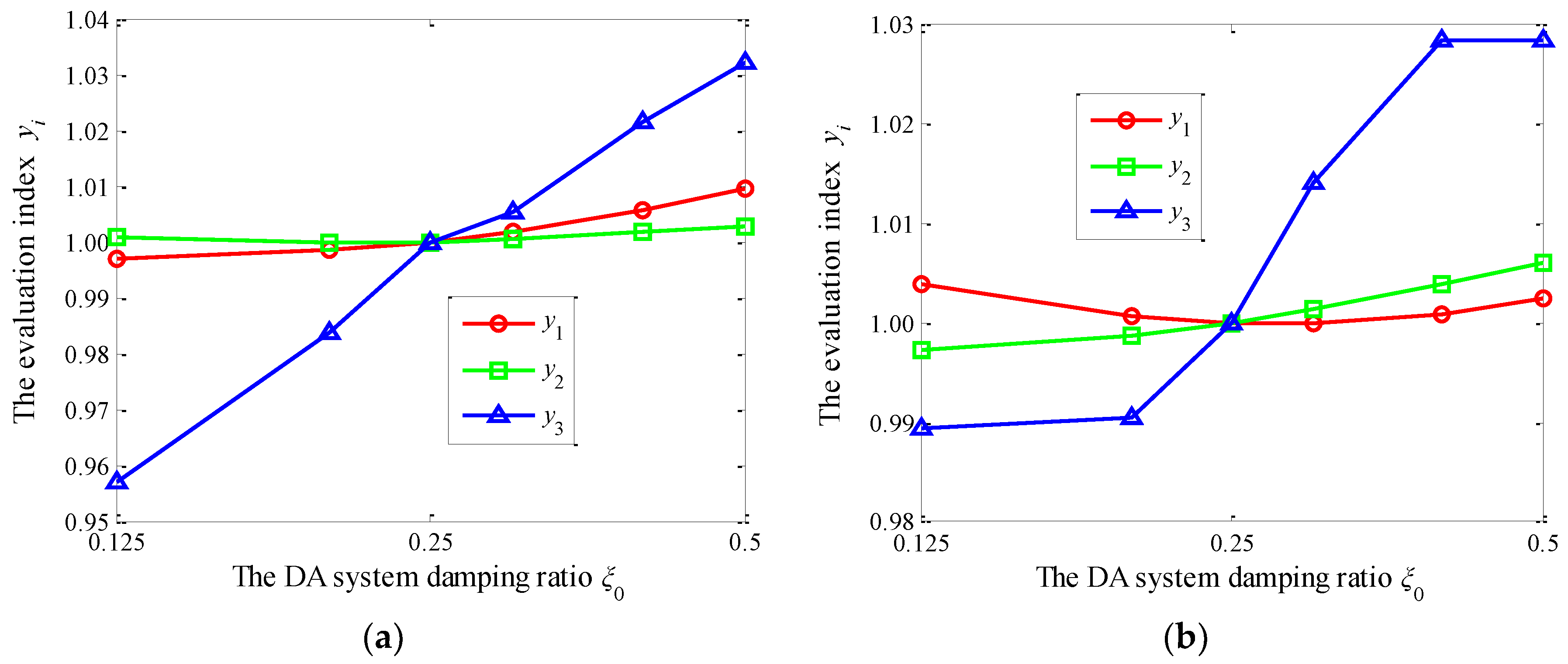
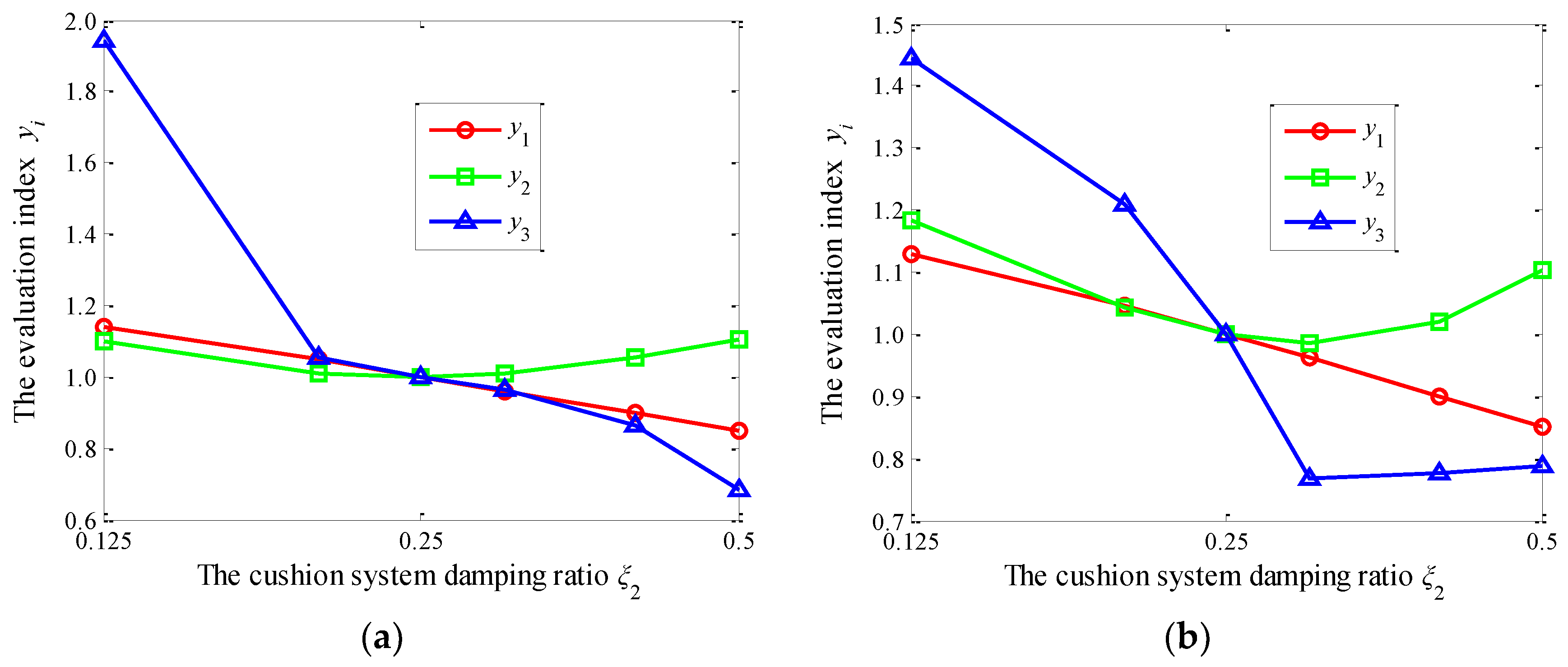
8.2. Influences of the Damping Ratios ξ0 and ξ2

Figure 15 and Figure 16 show the curves of the evaluation indexes y1, y2, and y3 versus the damping ratios of ξ0 and ξ2, respectively. By comparing Figure 15a,b, it can be seen that the trends are similar, but there are also some subtle differences. For the wheelchair going up the step, y3 is almost proportional to ξ0. However, with the increase of ξ0, y3 nonlinearly increases. Reducing ξ0 helps to effectively improve the running safety. It can also be seen that y1 and y2 are not sensitive to the damping ratio ξ0. Figure 16a,b shows that an optimal value of ξ2 exists to minimize y2; ξ2 has a greater influence on y3, but it has little effect on y1 and y2. Increasing ξ2 helps to improve the running safety and reduce the road impact.

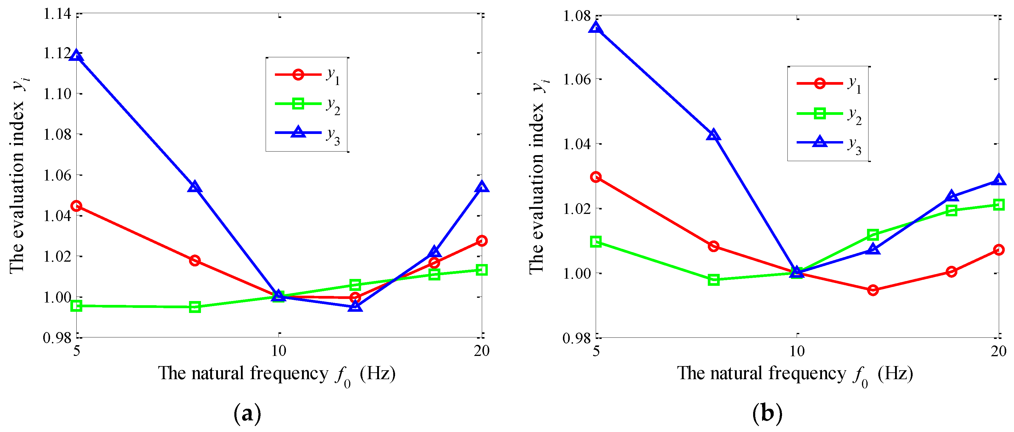
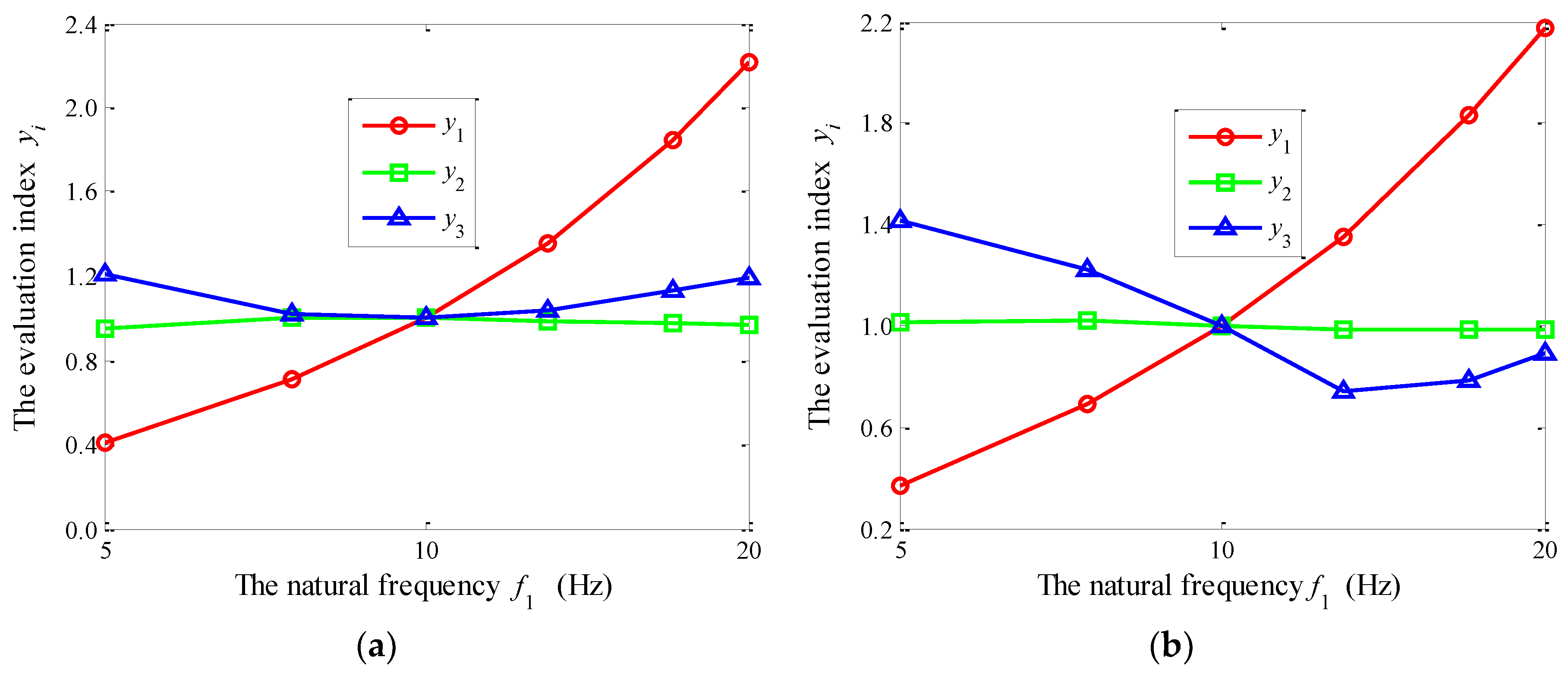
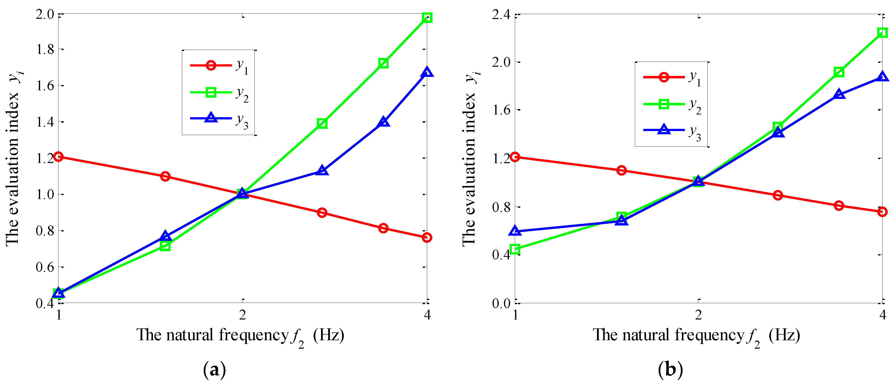
8.3. Influences of the Natural Frequencies f0, f1, and f2

Figure 17, Figure 18 and Figure 19 show the curves of the evaluation indexes y1, y2, and y3 versus the natural frequencies f0, f1, and f2, respectively.
For the wheelchair going up the step, with the increase of f0, both y2 and y3 decrease firstly and then increase; however, y2 increases continuously, as shown in Figure 17a. For the wheelchair going down the step, with the increase of f0, y1, y2, and y3 decrease firstly and then increase, as shown in Figure 17b. y1 is very sensitive to f1, as shown in Figure 18. Thus, reducing f1 can help to reduce the impact of the road to the wheelchair body. As can be seen in Figure 18, f1 has a minimal effect on y2. From Figure 19, it can be seen that y1, y2, and y3 are very sensitive to f2; y1 is inversely proportional to f2; both y2 and y3 are approximately proportional to f2.

8.4. Sensitivity Calculation of the Vibration Responses

Based on the influence trends analysis of the characteristic parameters on the vibration responses yi, the sensitivity values were calculated. Table 7 provides the calculated results. The calculation formulae are as follows:
{ s y i = y ( U i + Δ U i ) y ( U i ) y ( U i ) / Δ U i U i s y = 1 n i = 1 n | s y i | ,
where n is the number of the intervals, i represents the ith interval; ΔUi refers to the incremental value of the characteristic parameter U in the ith interval; sy is the response sensitivity; and y represents VDV1, VDV2, and p.
From Table 7, it can be seen that the sensitivity values are not exactly the same for the wheelchair going up the step and going down the step. In both cases, VDV1 is the most sensitive to f1, and other influencing factors from strong to weak are f2, r2, ξ2, r0, f0, and ξ0. In both cases, VDV2 is the most sensitive to f2 and other influencing factors of VDV2 from strong to weak are ξ2, r2, f1, f0, ξ0, and r0. p is very sensitive to both ξ2 and f2. For the wheelchair going up the step, other influencing factors from strong to weak are f1, r2, f0, ξ0, and r0. However, for wheelchair going down the step, other influencing factors of VDV2 from strong to weak are f1, r2, r0, f0, and ξ0.

9. Conclusions

This paper introduces the DA to the electric wheelchair. A vibration model of the human-wheelchair system with the DA was created. Models of the road excitation for wheelchairs going up a step and going down a step were proposed, respectively. The vibration dose value VDV1 of the wheelchair body acceleration a1, the vibration dose value VDV2 of the human body acceleration a2, and the time ratio p were adopted as evaluation indexes of the vibration behaviors. The impact responses and the amplitude frequency characteristics were numerically simulated and compared. The influences of the tire static radius r and the characteristic parameters on the vibration behaviors were revealed. The results of this study demonstrate the following:
(1)
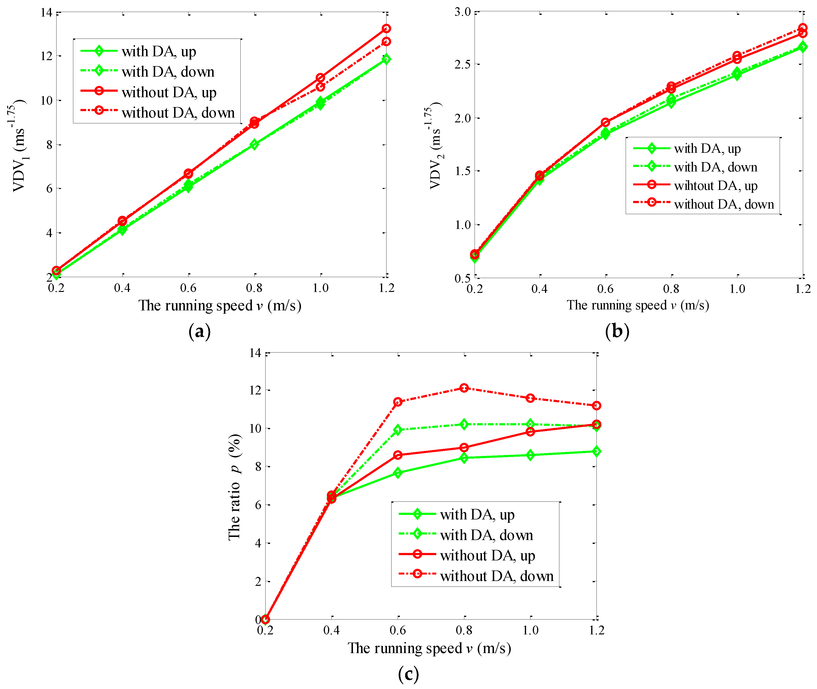
The three evaluation indexes are all improved by using the DA. When the wheelchair goes up the step and goes down the step, the differences for VDV1 and VDV2 are relatively smaller, but the differences for p are relatively larger.
(2)
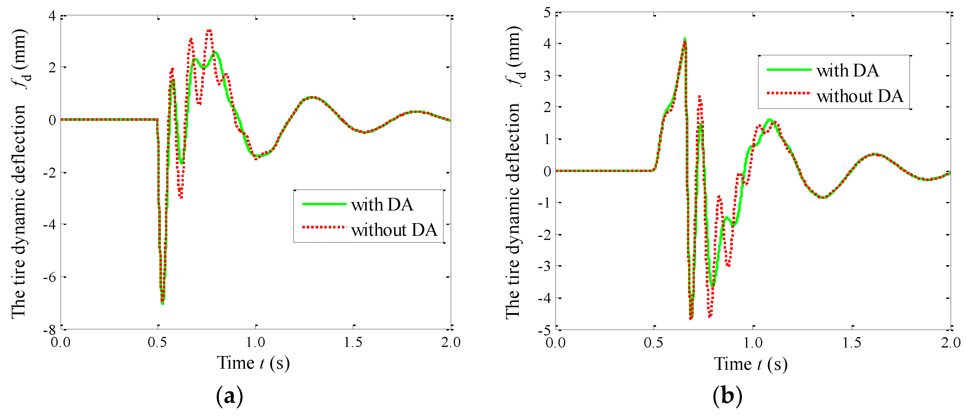
The DA can significantly reduce the amplitudes of |H1|, |H2|, and |H3| in the resonant region of the wheelchair body. Moreover, the DA does not lead to the vibration deterioration in the resonant region of the human body. The DA has the favorable effect of reducing the tire dynamic deflection and attenuating the vibration of the human body and the wheelchair body.
(3)
With the increase of the tire static radius r, the vibration responses VDV1, VDV2, and p decrease. Thus, increasing r contributes to the attenuation of the pavement impact. The sensitivity values of the vibration responses to the characteristic parameters are not exactly the same for the wheelchair going up the step and going down the step. In both cases, VDV1 is the most sensitive to f1, and VDV2 is the most sensitive to f2. Meanwhile, p is very sensitive to both ξ2 and f2.
The contribution of the experiment to the validation of the model is obviously limited; the model of the human-wheelchair system with the DA should be validated by test for further research. Moreover, the selection and matching of the DA should be discussed in detail.

Author Contributions

The corresponding author L.Z. proposed this research; L.Z. and S.W. performed the simulation; Y.H. and L.Z. analyzed the data; F.Y. reviewed and edited the manuscript; S.W. wrote the paper.

Funding

This work is supported by National Natural Science Foundation of China (No. 61627816), the National Key R&D Program of China (No. 2016YFC0701309).

Conflicts of Interest

The authors declare no conflict of interest.

References

  1. Kim, K.T.; Suk, H.I.; Lee, S.W. Commanding a brain-controlled wheelchair using steady-state somatosensory evoked potentials. IEEE Trans. Neural Syst. Rehabil. Eng. 2018, 26, 654–665. [Google Scholar] [CrossRef] [PubMed]
  2. Gong, D.X.; He, R.; Zuo, G.Y.; Yu, J.Y. Motion mapping in the joint space for the control of the heterogeneous wheelchair-mounted robotic arm. Acta Electron. Sin. 2018, 46, 464–472. [Google Scholar]
  3. Nguyen, V.T.; Jayawardena, C.; Ardekani, I. A navigation model for side-by-side robotic wheelchairs for optimizing social comfort in crossing situations. Robot. Auton. Syst. 2018, 100, 27–40. [Google Scholar] [CrossRef]
  4. Travlos, V.; Patman, S.; Wilson, A. Quality of life and psychosocial well-being in youth with neuromuscular disorders who are wheelchair users: A systematic review. Arch. Phys. Med. Rehabil. 2016, 98, 1004–1017. [Google Scholar] [CrossRef] [PubMed]
  5. Wu, B.F.; Chen, P.Y.; Lin, C.H. A New criterion of human comfort assessment for wheelchair robots by Q-Learning based accompanist tracking fuzzy controller. Int. J. Fuzzy Syst. 2016, 18, 1039–1053. [Google Scholar] [CrossRef]
  6. Routhier, F.; Lettre, J.; Miller, W.C.; Borisoff, J.F.; Keetch, K. Data logger technologies for manual wheelchairs: A scoping review. Assist. Technol. 2018, 30, 51–58. [Google Scholar] [CrossRef] [PubMed]
  7. Rojas, M.; Ponce, P.; Molina, A. A fuzzy logic navigation controller implemented in hardware for an electric wheelchair. Int. J. Adv. Robot. Syst. 2018, 15. [Google Scholar] [CrossRef] [Green Version]
  8. Pushp, S.; Saikia, A.; Khan, A.; Hazarika, S.M. A cognitively enhanced collaborative control architecture for an intelligent wheelchair: Formalization, implementation and evaluation. Cogn. Syst. Res. 2018, 49, 114–127. [Google Scholar] [CrossRef]
  9. Ma, K.; Qi, T.Z. A human-centered design of electric wheelchair controller with dual control access for both drivers of disabled people and caregiver. J. Comput. Inf. Sci. Eng. 2017, 17. [Google Scholar] [CrossRef]
  10. Arnay, R.; Hernández-Aceituno, J.; Toledo, J.; Acosta, L. Laser and Optical Flow Fusion for a Non-Intrusive Obstacle Detection System on an Intelligent Wheelchair. IEEE Sens. J. 2018, 18, 3799–3805. [Google Scholar] [CrossRef]
  11. Ktistakis, I.P.; Bourbakis, N.G. Assistive intelligent robotic wheelchairs. IEEE Potentials 2017, 36, 10–13. [Google Scholar] [CrossRef]
  12. Frank, A.O.; De Souza, L.H. Clinical features of children and adults with a muscular dystrophy using powered indoor/outdoor wheelchairs: Disease features, comorbidities and complications of disability. Disabil. Rehabil. 2018, 40, 1007–1013. [Google Scholar] [CrossRef] [PubMed]
  13. Kundu, A.S.; Lenka, P.K.; Lenka, P.K.; Bhaumik, S. Design and performance evaluation of 4 wheeled omni wheelchair with reduced slip and vibration. Procedia Comput. Sci. 2017, 105, 289–295. [Google Scholar] [CrossRef]
  14. Garcia-Mendenz, Y.; Pearlman, J.L.; Boninger, M.L.; Cooper, R.A. Health risks of vibration exposure to wheelchair users in the community. J. Spinal Cord Med. 2013, 36, 365–375. [Google Scholar] [CrossRef] [PubMed] [Green Version]
  15. Requejo, P.S.; Maneekobkunwong, S.; McNitt-Gray, J. Influence of hand-rim wheelchairs with rear suspension on seat forces and head accelerations during curb descent landings. J. Rehabil. Med. 2009, 41, 459–466. [Google Scholar] [CrossRef] [PubMed]
  16. BSI. BS EN 12183:2009 Manual Wheelchairs-Requirements and Test Methods; BSI: London, UK, 2009. [Google Scholar]
  17. RESNA. ANSI/RESNA WC-1:2009 Requirements and Test Methods for Wheelchairs (Including Scooters); RESNA: Washington, WA, USA, 2009. [Google Scholar]
  18. Standardization Administration of China. GB/T 13800-2009 Manual Wheelchairs; Standardization Administration of China: Beijing, China, 2009.
  19. Silva, L.C.; Dedini, F.G.; Corrêa, F.C.; Eckert, J.J.; Becker, M. Measurement of wheelchair contact force with a low cost bench test. Med. Eng. Phys. 2015, 38, 163–170. [Google Scholar] [CrossRef] [PubMed]
  20. Hillman, S.J.; Hollington, J.; Crossan, N. Correlation of ISO 16840-2:2007 impact damping and hysteresis measures for a sample of wheelchair seating cushions. Assist. Technol. 2018, 30, 77–83. [Google Scholar] [CrossRef] [PubMed]
  21. Wang, S.Y.; Sun, C.Y.; Wang, B.G. Preliminary study on comfortableness of motorized wheelchair cushion. J. Biomed. Eng. 2016, 33, 320–324. [Google Scholar]
  22. Brienza, D.; Vallely, J.; Karg, P.; Akins, J.; Gefen, A. An MRI investigation of the effects of user anatomy and wheelchair cushion type on tissue deformation. J. Tissue Viab. 2018, 27, 42–53. [Google Scholar] [CrossRef] [PubMed]
  23. Brown, K.; Flashner, H.; Mcnittgray, J.L. Modeling wheelchair-users undergoing vibrations. J. Biomech. Eng. 2017, 139. [Google Scholar] [CrossRef] [PubMed]
  24. Leary, M.; Gruijters, J.; Mazur, M.; Subic, A.; Burton, M. A fundamental model of quasi-static wheelchair biomechanics. Med. Eng. Phys. 2012, 34, 1278–1286. [Google Scholar] [CrossRef] [PubMed]
  25. Chen, X.Q.; Chase, J.G.; Wolm, P. System Identification and modelling of front wheel drive electric wheelchairs. In Proceedings of the 17th World Congress the International Federation of Automatic Control, Seoul, Korea, 6–11 July 2008. [Google Scholar]
  26. Salipur, Z.; Bertocci, G. Development and validation of rear impact computer simulation model of an adult manual transit wheelchair with a seated occupant. Med. Eng. Phys. 2010, 32, 66–75. [Google Scholar] [CrossRef] [PubMed] [Green Version]
  27. Ceravolo, E.; Gabellone, M.; Farina, M.; Bascetta, L.; Matteucci, M. Model Predictive Control of an autonomous wheelchair. IFAC PapersOnLine 2017, 50, 9821–9826. [Google Scholar] [CrossRef]
  28. Dziechciowski, Z.; Kromkaszydek, M. Vibration transmitted to the human body during the patient’s ride in a wheelchair. Arch. Acoust. 2017, 42, 137–148. [Google Scholar] [CrossRef]
  29. Hikmawan, M.F.; Nugraha, A.S. Analysis of electric wheelchair passenger comfort with a half car model approach. In Proceedings of the 2016 International Conference on Sustainable Energy Engineering and Application: Sustainable Energy for a Better Life, Jakarta, Indonesia, 3–5 October 2016. [Google Scholar]
  30. Miyawaki, K.; Takahashi, D. Investigation of whole-body vibration of passenger sitting on wheelchair and of passenger sitting on wheelchair loaded on lifter. In Proceedings of the 2016 International Symposium on Micro-NanoMechatronics and Human Science, Nagoya, Japan, 28–30 November 2016. [Google Scholar]
  31. Su, K.H.; Chang, T.H.; Su, S.F. Design of fuzzy-based magnetic suspension vibrator for electric wheelchair. In Proceedings of the IEEE 12th International Conference on Networking, Sensing and Control, Taipei, Taiwan, 9–11 April 2015. [Google Scholar]
  32. Ababou, A.; Ababou, N.; Morsi, T.; Boukhechem, L. Test bench for analysis of harmful vibrations induced to wheelchair users. In Proceedings of the Part of 7th International Joint Conference on Biomedical Engineering Systems and Technologies, Angers, France, 3–6 March 2014. [Google Scholar]
  33. Hischke, M.; Raoul, I.I. Effect of rear wheel suspension on tilt-in-space wheelchair shock and vibration attenuation. PM R 2018. [Google Scholar] [CrossRef] [PubMed]
  34. Egidio, A.D.; Leo, A.M.D.; Simoneschi, G. Effectiveness of mass–damper dynamic absorber on rocking block under one-sine pulse ground motion. Int. J. Non-Linear Mech. 2018, 98, 154–162. [Google Scholar]
  35. Orečný, M.; Štefan, S.; Huňady, R.; Želmíra, F. Application of a magneto-rheological damper and a dynamic absorber for a suspension of a working machine seat. Procedia Eng. 2014, 96, 338–344. [Google Scholar] [CrossRef]
Figure 1. The electric wheelchair: (a) a commercial product; (b) the vibration model.
Electronics 07 00087 g001
Figure 2. The step–road surface.
Electronics 07 00087 g002
Figure 3. The time histories of the step excitation q for the wheelchair: (a) going up the step; and (b) going down the step.
Electronics 07 00087 g003
Figure 4. Pulse test: (a) the test field; (b) the test equipment LMS Test.Lab; (c) the set up of the test.
Electronics 07 00087 g004
Figure 5. A comparison of the vibration behaviors of the human-wheelchair system with the dynamic absorber (DA) and without the DA undergoing the step: (a) VDV1 versus v; (b) VDV2 versus v; (c) p versus v.
Electronics 07 00087 g005
Figure 6. A comparison of the time histories of the wheelchair body acceleration a1 for the system with the DA and without the DA: (a) going up the step; (b) going down the step.
Electronics 07 00087 g006
Figure 7. A comparison of the time histories of the human body acceleration a2 for the system with the DA and without the DA: (a) going up the step; (b) going down the step.
Electronics 07 00087 g007
Figure 8. A comparison of the time histories of the tire dynamic deflection fd for the system with the DA and without the DA: (a) going up the step; (b) going down the step.
Electronics 07 00087 g008
Figure 9. A comparison of the amplitude frequency characteristics of the system with the DA and without the DA: (a) |H1| for the wheelchair versus f; (b) |H2| for the human versus f; (c) |H3| for the tire versus f.
Electronics 07 00087 g009
Figure 10. A comparison of the time histories of the wheelchair body acceleration a1 at different values of r for the wheelchair: (a) going up the step; (b) going down the step.
Electronics 07 00087 g010
Figure 11. A comparison of the time histories of the human body acceleration a2 at different values of r for the wheelchair: (a) going up the step; (b) going down the step.
Electronics 07 00087 g011
Figure 12. A comparison of the time histories of the human body acceleration a2 at different values of r for the wheelchair: (a) going up the step; (b) going down the step.
Electronics 07 00087 g012
Figure 13. The evaluation index yi versus the mass ratio r0 for the wheelchair: (a) going up the step; (b) going down the step.
Electronics 07 00087 g013
Figure 14. The evaluation index yi versus the mass ratio r2 for the wheelchair: (a) going up the step; (b) going down the step.
Electronics 07 00087 g014
Figure 15. The evaluation index yi versus the DA system damping ratio ξ0 for the wheelchair: (a) going up the step; (b) going down the step.
Electronics 07 00087 g015
Figure 16. The evaluation index yi versus the cushion system damping ratio ξ2 for the wheelchair: (a) going up the step; (b) going down the step.
Electronics 07 00087 g016
Figure 17. The evaluation index yi versus the natural frequency f0 for the wheelchair: (a) going up the step; (b) going down the step.
Electronics 07 00087 g017
Figure 18. The evaluation index yi versus the natural frequency f1 for the wheelchair: (a) going up the step; (b) going down the step.
Electronics 07 00087 g018
Figure 19. The evaluation index yi versus the natural frequency f2 for the wheelchair: (a) going up the step; (b) going down the step.
Electronics 07 00087 g019
Table 1. The values of the parameters for the human-wheelchair system.
ParameterValueParameterValue
m2 (kg)75K2 (N/mm)11.84
m1 (kg)25K1 (N/mm)98.70
C2 (Ns/m)377r (mm)250
Table 2. A comparison of the calculated values of vibration dose values (VDV2) for the wheelchair going up the step.
Running Speed v
(m/s)
The Tested VDV2
(ms−1.75)
The Simulated VDV2
(ms−1.75)
The Relative Deviation
(%)
0.20.700.745.7
0.41.481.425.1
0.61.901.973.7
0.82.252.364.9
Table 3. A comparison of the calculated values of VDV2 for the wheelchair going down the step.
Running Speed v
(m/s)
The Tested VDV2
(ms−1.75)
The Simulated VDV2
(ms−1.75)
The Relative Deviation
(%)
0.20.710.692.8
0.41.451.403.4
0.61.761.674.0
0.82.101.928.6
Table 4. The values of the parameters for the human-wheelchair system.
ParameterValueParameterValue
m2 (kg)75K2 (N/mm)11.84
m1 (kg)25K1 (N/mm)98.70
m0 (kg)2.5K0 (N/mm)9.87
C2 (Ns/m)377r (mm)250
C0 (Ns/m)78
Table 5. The calculated results of the vibration responses.
r (mm)VDV1 (ms−1.75)VDV2 (ms−1.75)p (%)
UpDownUpDownUpDown
2005.565.661.861.717.487.68
2504.874.941.701.587.465.64
3004.394.461.571.497.355.62
Table 6. The values of the characteristic parameters.
Characteristic ParameterBaseline+100%−50%
r23.06.01.5
r00.100.050.20
ξ20.250.50.125
ξ00.250.50.125
f22.04.01.0
f110.020.05.0
f010.020.05.0
Table 7. The calculated results of the vibration response sensitivity.
System Parameter S VDV 1 S VDV 2 Sp
UpDownUpDownUpDown
r00.2580.2810.0010.0910.1910.345
r20.5210.5320.3050.2320.5000.606
ξ00.0900.0650.0500.0780.2300.178
ξ20.4540.4400.3540.4570.9070.780
f00.2270.1870.1120.1550.3650.277
f11.0951.1010.2560.1830.5310.773
f20.5560.5611.0111.0870.9220.914

