
Assessment of a Smart Sensing Shoe for Gait Phase Detection in Level Walking


Abstract
:1. Introduction
2. Material and Methods
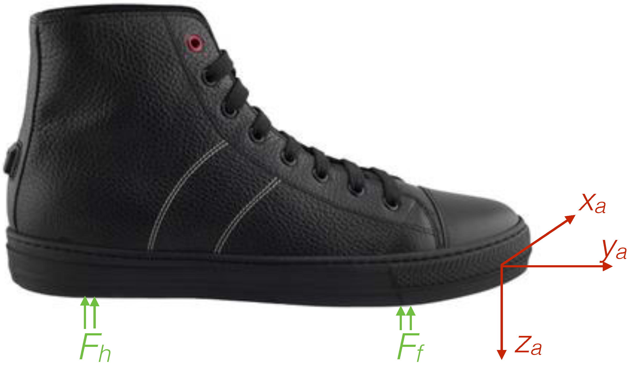
2.1. FootMoov
2.2. Gait Phase Detection
2.2.1. Signal Pre-Processing
2.2.2. Detection Algorithm
- E1 (Heel-strike to Stance): in the Heel-strike state, Stance is detected when both heel and fore-foot sensors are loaded or the foot rotational velocity is close to zero ([ AND ] OR );
- E2 (Stance to Heel-off): in the Stance state, Heel-off is detected if the heel sensor is unloaded and the foot inclination angle (ψ) exceeds a certain threshold ( AND );
- E3 (Heel-off to Swing): in the Heel-off state, Swing is recognized if heel and fore-foot are unloaded and the rotational velocity turns from positive to negative ([ AND ] AND );
- E4 (Swing to Heel-strike): in the Swing state, Heel-strike is detected as the heel touches the ground and the heel sensor is loaded ().
2.3. Experiments
2.3.1. Free Walking Experiment
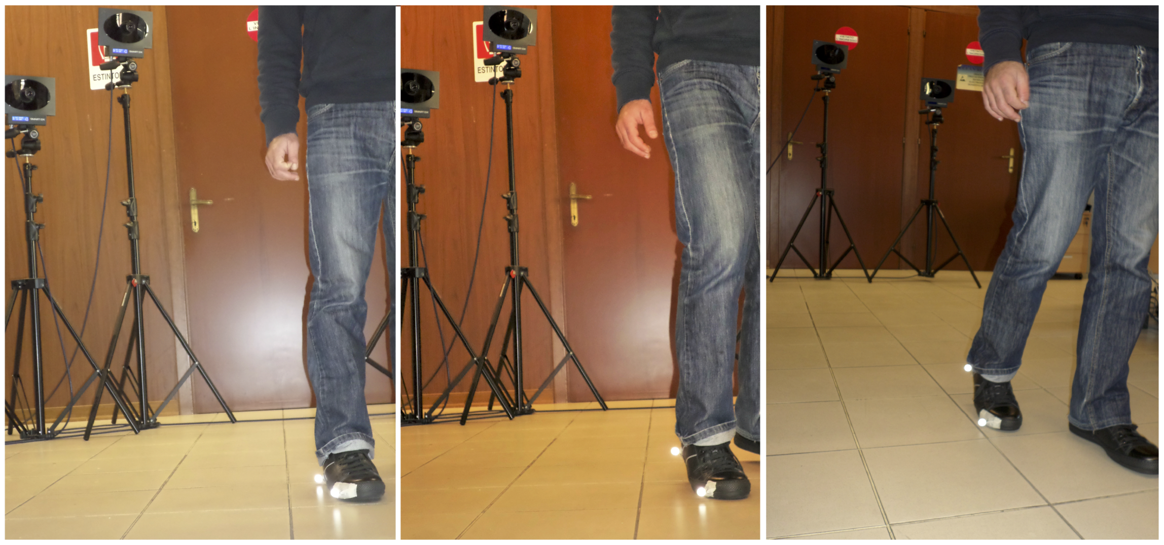
2.3.2. Motion Capture Experiment
3. Results and Discussion
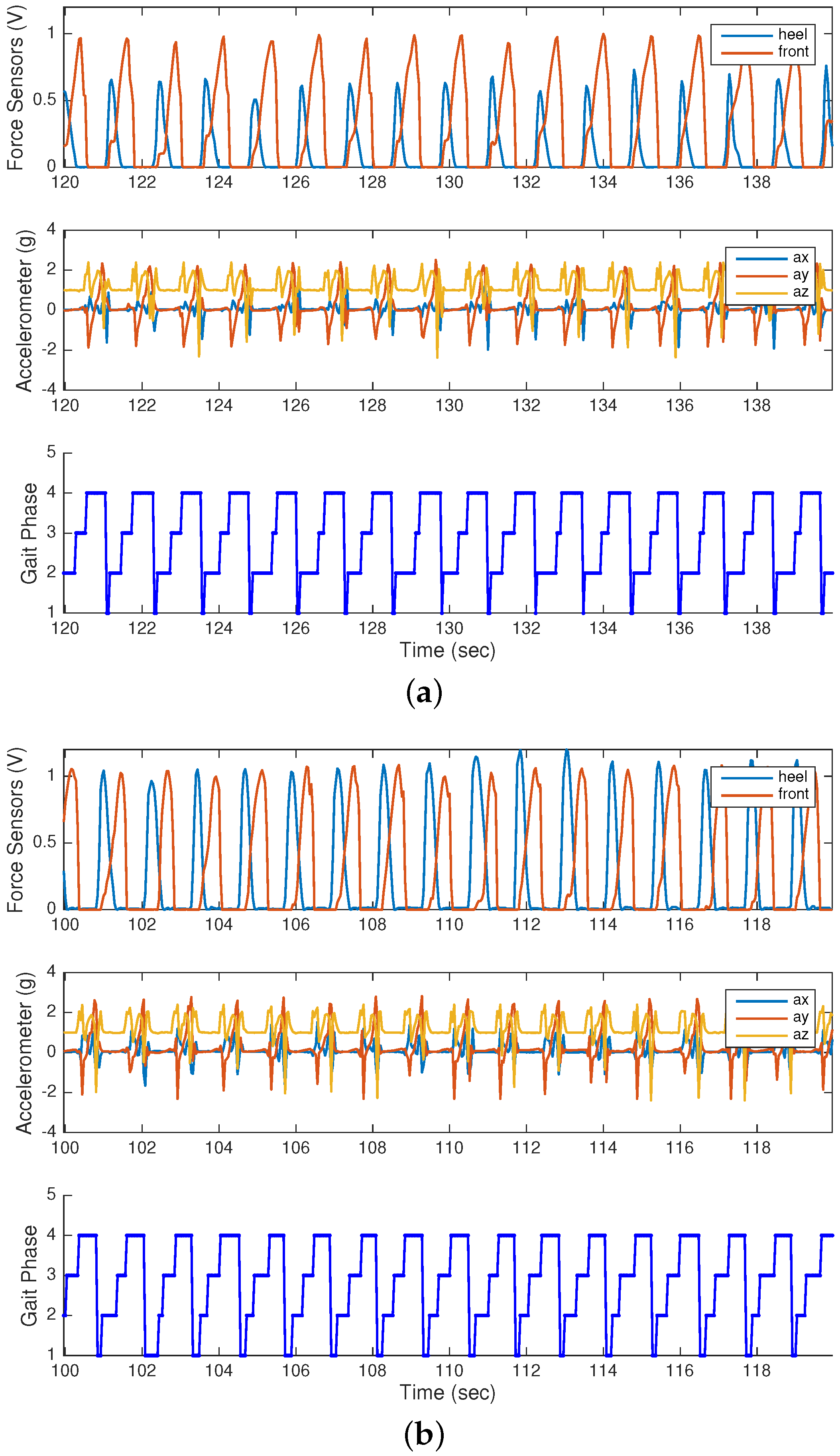
3.1. Free Walking Experiment
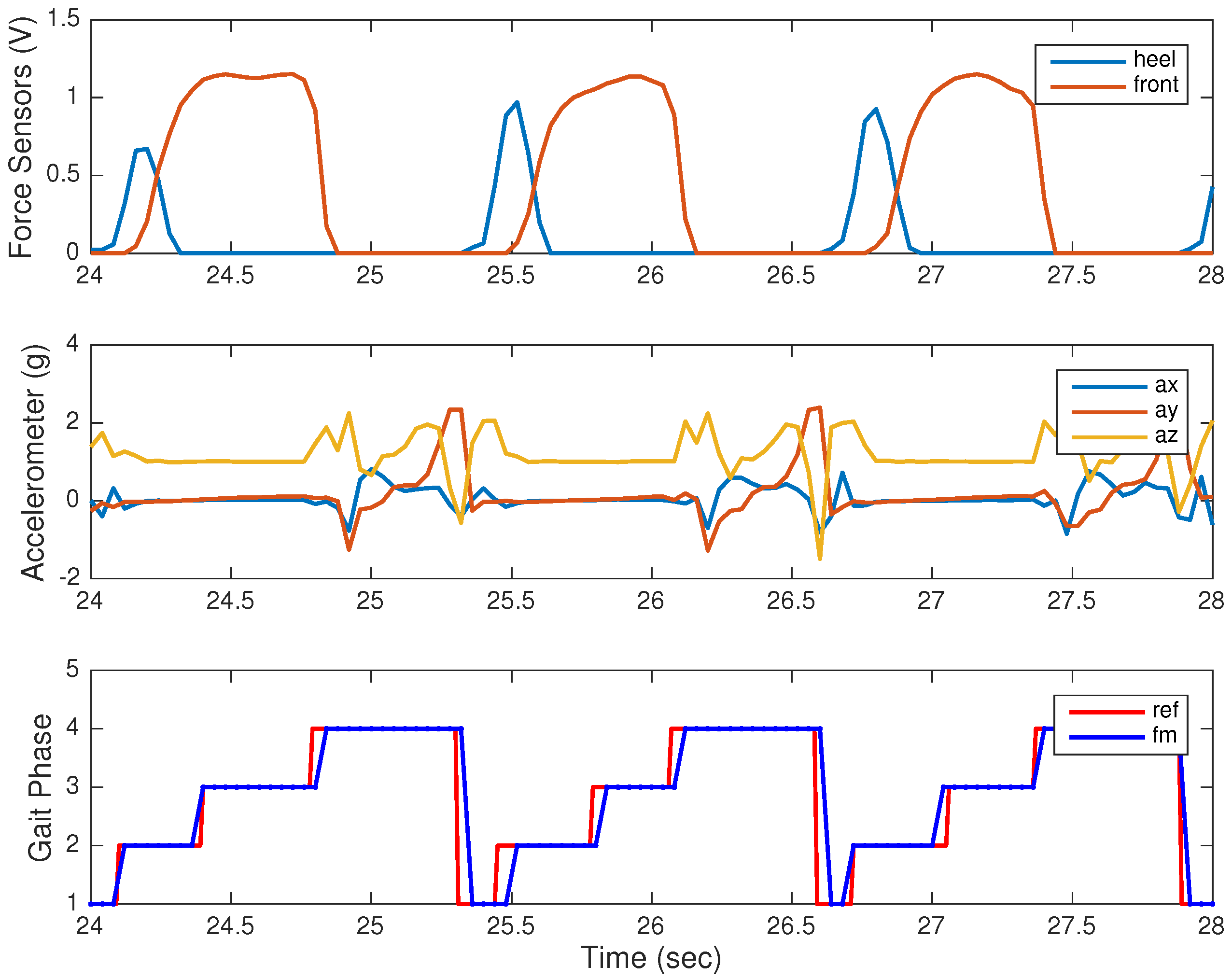
3.2. Motion Capture Experiment
3.3. Study Limitations
4. Conclusions
Acknowledgments
Author Contributions
Conflicts of Interest
Appendix A. Temporal and Spatial Gait Parameters
- Heel-strike: starts with the initial contact of the heel and ends when the entire foot is on the ground;
- Stance: the entire foot is in contact with the ground;
- Heel-off: the frontal part of the foot touches the ground while the heel is above the ground;
- Swing: the foot is not in contact with the ground and moves forward.
References
- Amft, O.; Habetha, J. Smart medical textiles for monitoring patients with heart conditions. In Smart Textiles for Medicine and Healthcare Materials, Systems and Applications; Woodhead Publishing Limited: Cambridge, UK, 2007; pp. 275–301. [Google Scholar]
- Valenza, G.; Nardelli, M.; Lanata, A.; Gentili, C.; Bertschy, G.; Paradiso, R.; Scilingo, E.P. Wearable monitoring for mood recognition in bipolar disorder based on history-dependent long-term heart rate variability analysis. IEEE J. Biomed. Health Inform. 2014, 18, 1625–1635. [Google Scholar] [CrossRef] [PubMed]
- Carbonaro, N.; Anania, G.; Mura, G.; Tesconi, M.; Tognetti, A.; Zupone, G.; de Rossi, D. Wearable biomonitoring system for stress management: A preliminary study on robust ECG signal processing. In Proceddings of the 2011 IEEE International Symposium on a World of Wireless, Mobile and Multimedia Networks (WoWMoM), Lucca, Italy, 20–24 June 2011.
- Patel, S.; Park, H.; Bonato, P.; Chan, L.; Rodgers, M. A review of wearable sensors and systems with application in rehabilitation. J. Neuroeng. Rehabil. 2012, 9, 1. [Google Scholar] [CrossRef] [PubMed]
- Tognetti, A.; Lorussi, F.; Dalle Mura, G.; Carbonaro, N.; Pacelli, M.; Paradiso, R.; de Rossi, D. New generation of wearable goniometers for motion capture systems. J. Neuroeng. Rehabil. 2014, 11. [Google Scholar] [CrossRef] [PubMed]
- Dalle Mura, G.; Lorussi, F.; Tognetti, A.; Anania, G.; Carbonaro, N.; Pacelli, M.; Paradiso, R.; de Rossi, D. Piezoresistive goniometer network for sensing gloves. In Proceddings of the XIII Mediterranean Conference on Medical and Biological Engineering and Computing 2013, Seville, Spain, 25–28 September 2013; Volume 41, pp. 1547–1550.
- Carbonaro, N.; Dalle Mura, G.; Lorussi, F.; Paradiso, R.; De Rossi, D.; Tognetti, A. Exploiting wearable goniometer technology for motion sensing gloves. IEEE J. Biomed. Health Inform. 2014, 18, 1788–1795. [Google Scholar] [CrossRef] [PubMed]
- Wagner, F.; Basran, J.; Dal Bello-Haas, V. A review of monitoring technology for use with older adults. J. Geriatr. Phys. Ther. 2012, 35, 28–34. [Google Scholar] [CrossRef] [PubMed]
- Baig, M.M.; Gholamhosseini, H.; Connolly, M.J. A comprehensive survey of wearable and wireless ECG monitoring systems for older adults. Med. Biol. Eng. Comput. 2013, 51, 485–495. [Google Scholar] [CrossRef] [PubMed]
- Bonfiglio, A.; Carbonaro, N.; Chuzel, C.; Curone, D.; Dudnik, G.; Germagnoli, F.; Hatherall, D.; Koller, J.; Lanier, T.; Loriga, G.; et al. Managing catastrophic events by wearable mobile systems. In Proceedings of the Mobile Response: First International Workshop on Mobile Information Technology for Emergency Response, Mobile Response 2007, Sankt Augustin, Germany, 22–23 February 2007; Revised Selected Papers; Lecture Notes in Computer Science. Springer: Berlin/Heidelberg, Germany, 2007; pp. 95–105. [Google Scholar]
- Klann, M. Tactical Navigation Support for Firefighters: The LifeNet Ad-Hoc Sensor-Network and Wearable System. In Proceedings of the Mobile Response: Second International Workshop on Mobile Information Technology for Emergency Response, MobileResponse 2008, Bonn, Germany, 29–30 May 2008; Revised Selected Papers; Lecture Notes in Computer Science. Springer: Berlin/Heidelberg, Germany, 2009; pp. 41–56. [Google Scholar]
- Tesconi, M.; Tognetti, A.; Scilingo, E.; Zupone, G.; Carbonaro, N.; De Rossi, D.; Castellini, E.; Marella, M. Wearable sensorized system for analyzing the lower limb movement during rowing activity. In Proceedings of the IEEE International Symposium on Industrial Electronics 2007, Vigo, Spain, 4–7 June 2007; pp. 2793–2796.
- Chambers, R.; Gabbett, T.J.; Cole, M.H.; Beard, A. The use of wearable microsensors to quantify sport-specific movements. Sports Med. 2015, 45, 1065–1081. [Google Scholar] [CrossRef] [PubMed]
- Redfern, J. The Evolution of Physical Activity and Recommendations for Patients with Coronary Heart Disease. Heart Lung Circ. 2016, 25, 759–764. [Google Scholar] [CrossRef] [PubMed]
- Arberet, S.; Lemay, M.; Renevey, P.; Sola, J.; Grossenbacher, O.; Andries, D.; Sartori, C.; Bertschi, M. Photoplethysmography-based ambulatory heartbeat monitoring embedded into a dedicated bracelet. Comput. Cardiol. 2013, 40, 935–938. [Google Scholar]
- Hataji, O.; Kobayashi, T.; Gabazza, E. Smart watch for monitoring physical activity in patients with chronic obstructive pulmonary disease. Respir. Investig. 2016, 54, 294–295. [Google Scholar] [CrossRef] [PubMed]
- Wile, D.; Ranawaya, R.; Kiss, Z. Smart watch accelerometry for analysis and diagnosis of tremor. J. Neurosci. Methods 2014, 230, 1–4. [Google Scholar] [CrossRef] [PubMed]
- Wijaya, R.; Setijadi, A.; Mengko, T.; Mengko, R. Heart rate data collecting using smart watch. In Proceedings of the 2014 IEEE 4th International Conference on System Engineering and Technology (ICSET 2014), Bandung, Indonesia, 24–25 November 2014.
- Militara, A.; Frandes, M.; Lungeanu, D. Smart wristbands as inexpensive and reliable non-dedicated solution for self-managing type 2 diabetes. In Proceedings of the 2015 E-Health and Bioengineering Conference (EHB 2015), Iasi, Romania, 19–21 November 2015.
- Perry, J.; Burnfield, J.M. Gait Analysis: Normal and Pathological Function; Slack: Thorofare, NJ, USA, 1992. [Google Scholar]
- Lopez-Meyer, P.; Fulk, G.D.; Sazonov, E.S. Automatic detection of temporal gait parameters in poststroke individuals. IEEE Trans. Inf. Technol. Biomed. 2011, 15, 594–601. [Google Scholar] [CrossRef] [PubMed]
- Balasubramanian, C.K.; Neptune, R.R.; Kautz, S.A. Variability in spatiotemporal step characteristics and its relationship to walking performance post-stroke. Gait Posture 2009, 29, 408–414. [Google Scholar] [CrossRef] [PubMed]
- Kotiadis, D.; Hermens, H.; Veltink, P. Inertial Gait Phase Detection for control of a drop foot stimulator: Inertial sensing for gait phase detection. Med. Eng. Phys. 2010, 32, 287–297. [Google Scholar] [CrossRef] [PubMed]
- Blaya, J.A.; Herr, H. Adaptive control of a variable-impedance ankle-foot orthosis to assist drop-foot gait. IEEE Trans. Neural Syst. Rehabil. Eng. 2004, 12, 24–31. [Google Scholar] [CrossRef] [PubMed]
- Lyons, G.M.; Sinkjær, T.; Burridge, J.H.; Wilcox, D.J. A review of portable FES-based neural orthoses for the correction of drop foot. IEEE Trans. Neural Syst. Rehabil. Eng. 2002, 10, 260–279. [Google Scholar] [CrossRef] [PubMed]
- Meyer-Heim, A.; Ammann-Reiffer, C.; Schmartz, A.; Schaefer, J.; Sennhauser, F.H.; Heinen, F.; Knecht, B.; Dabrowski, E.; Borggraefe, I. Improvement of walking abilities after robotic-assisted locomotion training in children with cerebral palsy. Arch. Dis. Child. 2009, 94, 615–620. [Google Scholar] [CrossRef] [PubMed]
- Thaler-Kall, K.; Peters, A.; Thorand, B.; Grill, E.; Autenrieth, C.S.; Horsch, A.; Meisinger, C. Description of spatio-temporal gait parameters in elderly people and their association with history of falls: Results of the population-based cross-sectional KORA-Age study. BMC Geriatr. 2015, 15, 32. [Google Scholar] [CrossRef] [PubMed]
- Nguyen, L.V.; La, H.M.; Sanchez, J.; Vu, T. A Smart Shoe for building a real-time 3D map. Autom. Constr. 2016, 71, 2–12. [Google Scholar] [CrossRef]
- Foxlin, E. Pedestrian tracking with shoe-mounted inertial sensors. IEEE Comput. Graph. Appl. 2005, 25, 38–46. [Google Scholar] [CrossRef] [PubMed]
- Jiménez, A.R.; Seco, F.; Prieto, J.C.; Guevara, J. Indoor pedestrian navigation using an INS/EKF framework for yaw drift reduction and a foot-mounted IMU. In Proceedings of the 2010 7th IEEEWorkshop on Positioning Navigation and Communication (WPNC), Dresden, Germany, 11–12 March 2010; pp. 135–143.
- Van Nguyen, L.; La, H.M. A human foot motion localization algorithm using IMU. In Proceedings of the 2016 American Control Conference (ACC), Boston, MA, USA, 6–8 July 2016; pp. 4379–4384.
- Rueterbories, J.; Spaich, E.G.; Larsen, B.; Andersen, O.K. Methods for gait event detection and analysis in ambulatory systems. Med. Eng. Phys. 2010, 32, 545–552. [Google Scholar] [CrossRef] [PubMed]
- Taborri, J.; Palermo, E.; Rossi, S.; Cappa, P. Gait partitioning methods: A systematic review. Sensors 2016, 16, 66. [Google Scholar] [CrossRef] [PubMed]
- Mansfield, A.; Lyons, G.M. The use of accelerometry to detect heel contact events for use as a sensor in FES assisted walking. Med. Eng. Phys. 2003, 25, 879–885. [Google Scholar] [CrossRef]
- Aminian, K.; Najafi, B.; Büla, C.; Leyvraz, P.F.; Robert, P. Spatio-temporal parameters of gait measured by an ambulatory system using miniature gyroscopes. J. Biomech. 2002, 35, 689–699. [Google Scholar] [CrossRef]
- Williamson, R.; Andrews, B.J. Gait event detection for FES using accelerometers and supervised machine learning. IEEE Trans. Rehabil. Eng. 2000, 8, 312–319. [Google Scholar] [CrossRef] [PubMed]
- Mannini, A.; Sabatini, A.M. Gait phase detection and discrimination between walking–jogging activities using hidden Markov models applied to foot motion data from a gyroscope. Gait Posture 2012, 36, 657–661. [Google Scholar] [CrossRef] [PubMed]
- Taborri, J.; Rossi, S.; Palermo, E.; Patanè, F.; Cappa, P. A novel HMM distributed classifier for the detection of gait phases by means of a wearable inertial sensor network. Sensors 2014, 14, 16212–16234. [Google Scholar] [CrossRef] [PubMed]
- Van Nguyen, L.; La, H.M. Real-Time Human Foot Motion Localization Algorithm With Dynamic Speed. IEEE Trans. Hum.-Mach. Syst. 2016. [Google Scholar] [CrossRef]
- Smith, B.T.; Coiro, D.J.; Finson, R.; Betz, R.R.; McCarthy, J. Evaluation of force-sensing resistors for gait event detection to trigger electrical stimulation to improve walking in the child with cerebral palsy. IEEE Trans. Neural Syst. Rehabil. Eng. 2002, 10, 22–29. [Google Scholar] [CrossRef] [PubMed]
- Edgar, S.R.; Swyka, T.; Fulk, G.; Sazonov, E.S. Wearable shoe-based device for rehabilitation of stroke patients. In Proceedings of the 2010 Annual International Conference of the IEEE Engineering in Medicine and Biology, Buenos Aires, Argentina, 31 August–4 September 2010; 2010; pp. 3772–3775. [Google Scholar]
- Kong, K.; Tomizuka, M. Smooth and continuous human gait phase detection based on foot pressure patterns. In Proceedings of the IEEE International Conference on Robotics and Automation (ICRA 2008), Pasadena, CA, USA, 19–23 May 2008; pp. 3678–3683.
- Pappas, I.P.; Popovic, M.R.; Keller, T.; Dietz, V.; Morari, M. A reliable gait phase detection system. IEEE Trans. Neural Syst. Rehabil. Eng. 2001, 9, 113–125. [Google Scholar] [CrossRef] [PubMed]
- Senanayake, C.M.; Senanayake, S.A. Computational intelligent gait-phase detection system to identify pathological gait. IEEE Trans. Inf. Technol. Biomed. 2010, 14, 1173–1179. [Google Scholar] [CrossRef] [PubMed]
- Hegde, N.; Sazonov, E. SmartStep: A Fully Integrated, Low-Power Insole Monitor. Electronics 2014, 3, 381–397. [Google Scholar] [CrossRef]
- Tareco, J.M.; Miller, N.H.; MacWilliams, B.A.; Michelson, J.D. Defining flatfoot. Foot Ankle Int. 1999, 20, 456–460. [Google Scholar] [CrossRef] [PubMed]
- Mueller, M.J.; Hastings, M.; Commean, P.K.; Smith, K.E.; Pilgram, T.K.; Robertson, D.; Johnson, J. Forefoot structural predictors of plantar pressures during walking in people with diabetes and peripheral neuropathy. J. Biomech. 2003, 36, 1009–1017. [Google Scholar] [CrossRef]
- Sazonov, E.S.; Bumpus, T.; Zeigler, S.; Marocco, S. Classification of plantar pressure and heel acceleration patterns using neural networks. In Proceedings of the 2005 IEEE International Joint Conference on Neural Networks, Montreal, QC, Canada, 31 July–4 August 2005; Volume 5, pp. 3007–3010.
- Sazonov, E.S.; Fulk, G.; Hill, J.; Schutz, Y.; Browning, R. Monitoring of posture allocations and activities by a shoe-based wearable sensor. IEEE Trans. Biomed. Eng. 2011, 58, 983–990. [Google Scholar] [CrossRef] [PubMed]
- Tang, W.; Sazonov, E.S. Highly accurate recognition of human postures and activities through classification with rejection. IEEE J. Biomed. Health Inform. 2014, 18, 309–315. [Google Scholar] [CrossRef] [PubMed]
- Fulk, G.D.; Sazonov, E. Using sensors to measure activity in people with stroke. Top. Stroke Rehabil. 2011, 18, 746–757. [Google Scholar] [CrossRef] [PubMed]
- Zhang, T.; Fulk, G.D.; Tang, W.; Sazonov, E.S. Using decision trees to measure activities in people with stroke. In Proceedings of the 2013 35th Annual International Conference of the IEEE Engineering in Medicine and Biology Society (EMBC), Osaka, Japan, 3–7 July 2013; pp. 6337–6340.
- Zhang, T.; Lu, J.; Uswatte, G.; Taub, E.; Sazonov, E.S. Measuring gait symmetry in children with cerebral palsy using the SmartShoe. In Proceedings of the 2014 IEEE Healthcare Innovation Conference (HIC), Seattle, WA, USA, 8–10 October 2014; pp. 48–51.
- Bae, J.; Kong, K.; Byl, N.; Tomizuka, M. A mobile gait monitoring system for abnormal gait diagnosis and rehabilitation: A pilot study for Parkinson disease patients. J. Biomech. Eng. 2011, 133, 041005. [Google Scholar] [PubMed]
- F-Scan System. Available online: https://www.tekscan.com/products-solutions/systems/f-scan-system (accessed on 10 August 2016).
- Pedar System. Available online: http://novel.de/novelcontent/pedar (accessed on 10 August 2016).
- Lemaire, E.D.; Biswas, A.; Kofman, J. Plantar pressure parameters for dynamic gait stability analysis. In Proceedings of the 28th Annual International Conference of the IEEE Engineering in Medicine and Biology Society, New York, NY, USA, 30 August–3 September 2006; pp. 4465–4468.
- Catalfamo, P.; Moser, D.; Ghoussayni, S.; Ewins, D. Detection of gait events using an F-Scan in-shoe pressure measurement system. Gait Posture 2008, 28, 420–426. [Google Scholar] [CrossRef] [PubMed]
- El Kati, R.; Forrester, S.; Fleming, P. Evaluation of pressure insoles during running. Procedia Eng. 2010, 2, 3053–3058. [Google Scholar] [CrossRef]
- FootMoov. Available online: http://www.footmoov.com (accessed on 5 August 2016).
- Tognetti, A.; Lorussi, F.; Carbonaro, N.; de Rossi, D. Wearable Goniometer and Accelerometer Sensory Fusion for Knee Joint Angle Measurement in Daily Life. Sensors 2015, 15, 28435. [Google Scholar] [CrossRef] [PubMed]
- Sciavicco, L.; Siciliano, B. Modelling and Control of Robot Manipulators; Springer-Verlag: London, UK, 2000. [Google Scholar]
- Karantonis, D.M.; Narayanan, M.R.; Mathie, M.; Lovell, N.H.; Celler, B.G. Implementation of a real-time human movement classifier using a triaxial accelerometer for ambulatory monitoring. IEEE Trans. Inf. Technol. Biomed. 2006, 10, 156–167. [Google Scholar] [CrossRef] [PubMed]
- Luinge, H.J.; Veltink, P.H. Inclination measurement of human movement using a 3-D accelerometer with autocalibration. IEEE Trans. Neural Syst. Rehabil. Eng. 2004, 12, 112–121. [Google Scholar] [CrossRef] [PubMed]
- Sabatini, A.M.; Martelloni, C.; Scapellato, S.; Cavallo, F. Assessment of walking features from foot inertial sensing. IEEE Trans. Biomed. Eng. 2005, 52, 486–494. [Google Scholar] [CrossRef] [PubMed]
- BTS SMART-DX. Available online: www.btsbioengineering.com/products/kinematics/bts-smart-dx (accessed on 10 August 2016).
- Truong, P.H.; Lee, J.; Kwon, A.R.; Jeong, G.M. Stride Counting in Human Walking and Walking Distance Estimation Using Insole Sensors. Sensors 2016, 16, 823. [Google Scholar] [CrossRef] [PubMed]
- Pappas, I.P.I.; Keller, T.; Mangold, S.; Popovic, M.R.; Dietz, V.; Morari, M. A reliable gyroscope-based gait-phase detection sensor embedded in a shoe insole. IEEE Sens. J. 2004, 4, 268–274. [Google Scholar] [CrossRef]
- Winter, D.A. Biomechanics and Motor Control of Human Gait: Normal, Elderly and Pathological; University of Waterloo Press: Waterloo, ON, Canada, 1991. [Google Scholar]


| Age (Mean ± Std) [Years] | Weight (Mean ± Std) [kg] | Height (Mean ± Std) [m] |
|---|---|---|
| 26.75 ± 3.1 | 76.875 ± 8.5 | 1.768 ± 0.06 |
| Mean [s] | Std [s] | p | ||
|---|---|---|---|---|
| HS | REF | 0.125 | 0.013 | |
| FM | 0.117 | 0.03 | ||
| e | 0.008 | 0.028 | 0.3 | |
| ST | REF | 0.350 | 0.057 | |
| FM | 0.310 | 0.098 | ||
| e | 0.039 | 0.065 | 0.07 | |
| HO | REF | 0.293 | 0.061 | |
| FM | 0.249 | 0.099 | ||
| e | 0.044 | 0.07 | 0.12 | |
| SW | REF | 0.535 | 0.043 | |
| FM | 0.514 | 0.036 | ||
| e | 0.021 | 0.050 | 0.25 |
© 2016 by the authors; licensee MDPI, Basel, Switzerland. This article is an open access article distributed under the terms and conditions of the Creative Commons Attribution (CC-BY) license (http://creativecommons.org/licenses/by/4.0/).
Share and Cite
Carbonaro, N.; Lorussi, F.; Tognetti, A. Assessment of a Smart Sensing Shoe for Gait Phase Detection in Level Walking. Electronics 2016, 5, 78. https://doi.org/10.3390/electronics5040078
Carbonaro N, Lorussi F, Tognetti A. Assessment of a Smart Sensing Shoe for Gait Phase Detection in Level Walking. Electronics. 2016; 5(4):78. https://doi.org/10.3390/electronics5040078
Chicago/Turabian StyleCarbonaro, Nicola, Federico Lorussi, and Alessandro Tognetti. 2016. "Assessment of a Smart Sensing Shoe for Gait Phase Detection in Level Walking" Electronics 5, no. 4: 78. https://doi.org/10.3390/electronics5040078
APA StyleCarbonaro, N., Lorussi, F., & Tognetti, A. (2016). Assessment of a Smart Sensing Shoe for Gait Phase Detection in Level Walking. Electronics, 5(4), 78. https://doi.org/10.3390/electronics5040078