Integration of Organic Light Emitting Diodes and Organic Photodetectors for Lab-on-a-Chip Bio-Detection Systems

Abstract
:1. Introduction
2. Operation Principles of Organic Light Emitting Diodes and Organic Photodetectors

- -
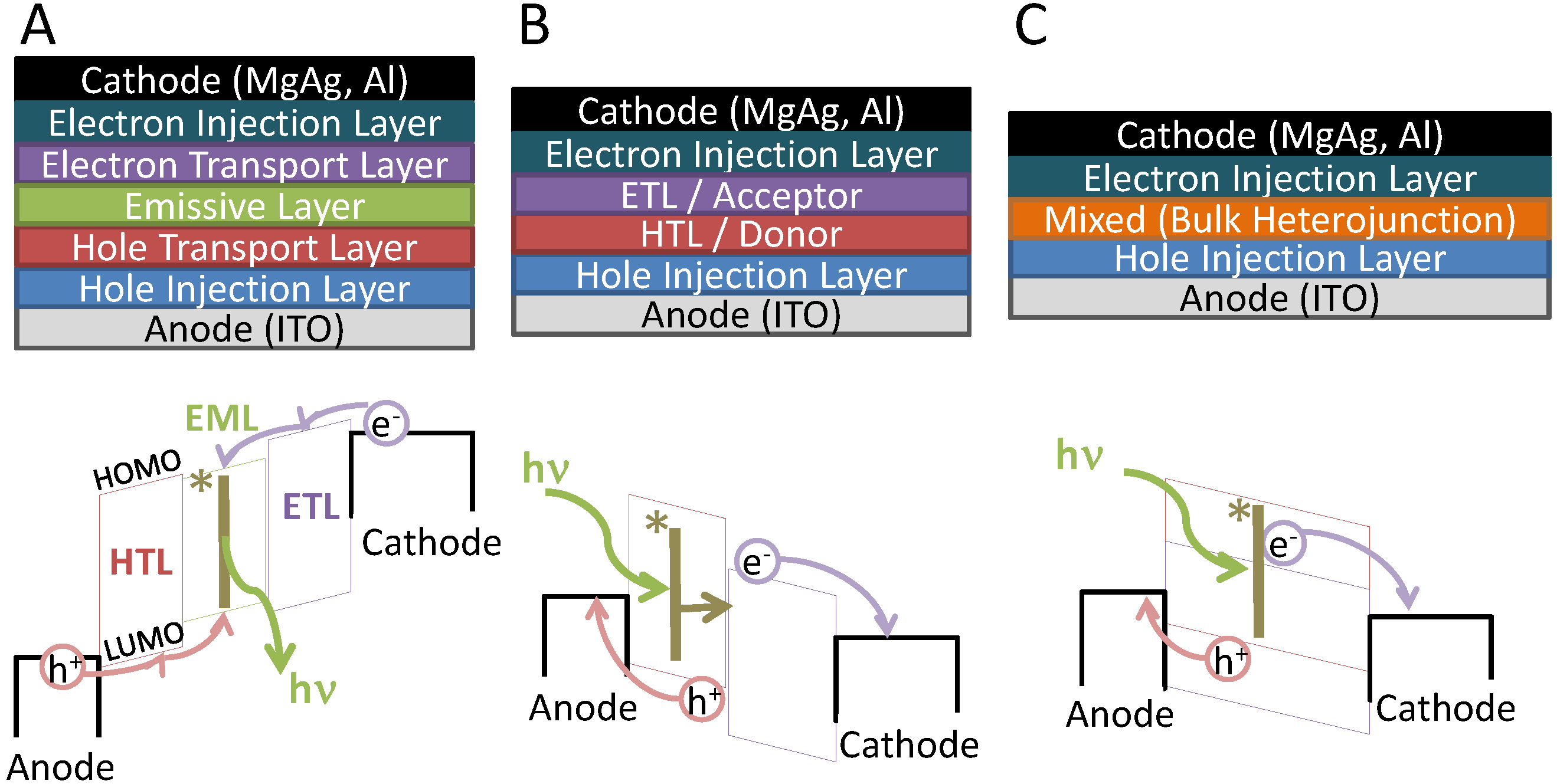
- A negative bias is applied to the cathode / a positive bias is applied to the anode
- -
- A hole is injected (either by thermionic or field emission) into the HTL and an electron is similarly injected into the ETL
- -
- The electron and hole meet in the EML, form an exciton (denoted as *|), and recombine to emit a photon with energy hν, proportional to the energy gap of the emissive layer.
- -
- A negative bias is applied to the anode / a positive bias is applied to the cathode
- -
- A photon is absorbed by either the donor or acceptor material (in Figure 1, the photon is absorbed by the donor material) to generate an exciton (denoted as *|)
- ○
- the exciton traverses to the donor/acceptor interface to dissociate into its constituent electron and hole
- -
- The electrons and holes travel along the ETL and HTL to be collected at the cathode and anode respectively.
3. Early Integration of Optical Excitation and Detection into Lab-on-a-Chip

4. Integrated Organic Light Emitting Diode and Organic Photodetector Lab-on-a-Chip Systems
- -
- use micro-cavity effects (with a semi-reflective anode instead of the transparent anode shown in Figure 1) or distributed Bragg reflectors (DBRs) to substantially narrow the FWHM of the OLED emission peak and remove tail-end emission
- ○
- -
- operate the OLED in pulsed mode and exploit differences in electroluminescence (EL) response/decay time versus the fluorophore PL response/decay time
- ○
- If the OLED and the fluorophore are selected appropriately, it may be feasible to offset the OLED’s emission and the OPD’s detection.
- ○
- In some cases, high current pulse operation has allowed for very high brightness values in OLEDs, which may further enhance PL [52].
- -
- use clever design techniques to minimize the excitation light coupled into the OPD
- ○
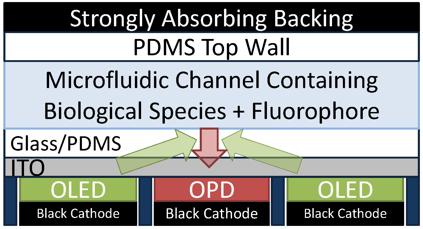
- For example, see Figure 4, which is a suggested back-detection device and is discussed further below. Shinar and coworkers used a much simpler implementation of a back-detection device (with a PMT detector and with no efforts to block or shield excitation light) to some success for their oxygen sensors [53,54,55,56,57]
- -
- incorporate thin film absorbers or polarizers (e.g., following work by Ryu et al. [46])
- ○
- While these techniques are the simplest, they also serve to substantially decrease the intensity of the PL signal. They may therefore not be suitable to adequately reduce noise and to provide competitive SNR values that can compete with present lab-scale LIF systems.
- ○
- To minimize the number of components required in the LoC system, it may be feasible to employ excitation sources that emit polarized light without the use of linear polarizers. Such excitation sources have recently been demonstrated with polymer emitting nanofibres, showing the potential for electrical excitation (when incorporated in polymer OLED-like devices) [58], as well as demonstrating reasonable integration into microfluidic systems [59].

4.1. Organic Light Emitting Diode-Integrated Lab-on-a-Chip Systems

| Application | Micro-Fluidic | OLED Details | Detector | Analyte | Dynamic Range | Ref. | |
|---|---|---|---|---|---|---|---|
| Dye conc | PL | PDMS channel | ITO/α-NPD/Alq3/LiF/Al | CCD w/ fibre | RhB | 5–100 μM | [63,64] |
| ITO/α-NPD/Alq3:C6/Alq3/LiF/Al | |||||||
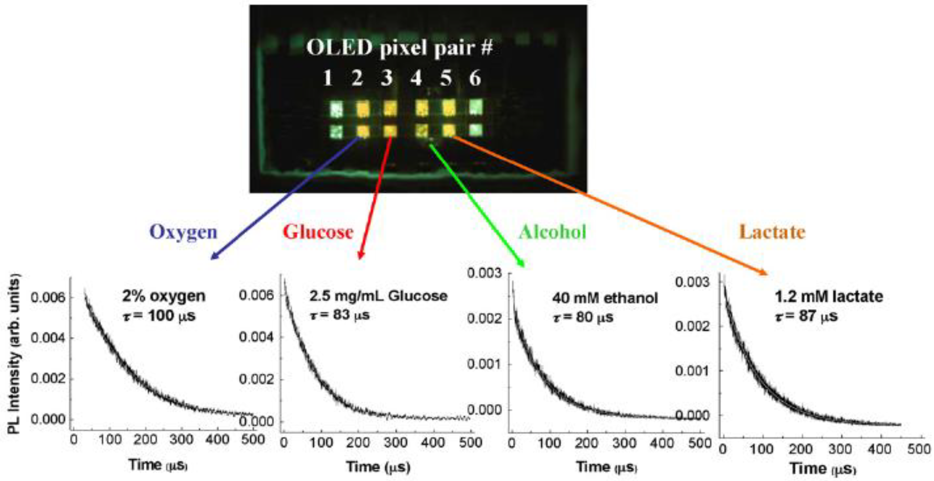
| Multi-analyte conc | PLq | film (non-MF), PP channel | ITO/CuPc/a-NPD/DPVBi/Alq3/CsF/Al | PMT, Si PD + pre-amp | glucose, lactate, ethanol | 0.02–0.3 mM | [53,54,55,56,57,65] |
| ITO/CuPc/a-NPD/Alq3/CsF/Al | O2 | 0–100% | |||||
| ITO/CuPc/NPD/Alq3:C545T/Alq3/LiF/Al | dissolved O2 | 2–40 ppm | |||||
| EP sep’n, immune assay | PL | etched glass, PDMS channel | ITO/PEDOT:PSS/(PF or PPV emitter)/LiF/Al | PMT, Si APD w/ filter, lens, fibre | fluorescein | 1 μM–10 mM | [66,67] |
| HSA | 10–100 mg/L | ||||||
| Dye conc, IEF | PL | PDMS channel | ITO/NPB/Alq3/Mg:Ag/Ag | PMT, CCD w/ filter, lens | rhodamine 6G, Alexa Fluor 532 | 50–700 μM | [68,69,70] |
| commercial AM-OLED array | R-phyco-erythrin | 38 ng/mL–50 μg/mL | |||||
| Dye conc, immune assay | PL | etched glass, PDMS channel | ITO/CuPc/α-NPD/Alq3/LiF/Al | p-i-n, p+n PD | TAMRA | 10–100 μM | [71,72] |
| Rh6G | 1–100 μM | ||||||
| Analyte conc | IV | droplet | ITO/TPD/Alq3/Al | N/A | ethanol, methanol | 10–1E3 ppm | [73] |
| Dye conc | PL | PDMS channel | AZO/PEDOT:PSS/PDY-132/Alq3/Ag | spectro-meter | sulforho-damine 101 | N/A | [74] |
| Dye conc, immuno assay | PL | PDMS channel | ITO/TPD/CBP:Ir(ppy)3/Bphen/Alq3/Mg:Ag/Ag | linear CCD w/ filter | resorufin | 7.8 μM–80 μM | [75] |
| IgA | 17–100 ng/mL | ||||||
| Dye conc | PL | PMMA channel | Alq3:DCM on DFB gratings, pumped w/ UV laser | spectro-meter w/ filter, lens | fluoro-spheres, Alexa 647 | N/A | [62] |
| Dye conc, immuno assay | PL | droplet | ITO/PEDOT:PSS/α-NPB/PBD/LiF/Al | CCD w/ filter | Alexa 430 | 156–1E4 pg | [76] |
| hTG2 antigen | 200–5E3 pg | ||||||


4.2. Organic Photodiode-Integrated Lab-on-a-Chip Systems
| Application | Micro-fluidic | OPD Details | Excitation Source | Analyte | Dynamic Range | Ref. | |
|---|---|---|---|---|---|---|---|
| H2O2/Anti-oxidant conc, TAC assay | CLCLq | PDMS channel | ITO/CuPc/C60/BCP/Al | N/A | H2O2 | 10 μM–1 M | [80,81,82] |
| β-Carotene | 22–200 μM | ||||||
| ITO/PEDOT:PSS/P3HT:PCBM/Al | α-Tocopherol | 10–200 μM | |||||
| Quercetin | 50–200 μM | ||||||
| Dye conc | CL | PDMS channel | ITO/PEDOT:PSS/CuPc/C60/LiF/Al | m-halide lamp w/ polarizer | Rh6g, fluorescein | 10 nM–10 μM | [83] |
| Immuno assay | CL | PDMS channel | ITO/PEDOT:PSS/P3HT:PCBM/Al | N/A | SEB | 0.1–50 ng/mL | [84] |
| Light scattering, cell counting | abs | PDMS channel | P3HT:PCBM-based OPD (spraycoat) | 488 nm laser | HeLa, NHDF, Jurkat cells | 4E3–3E5 cells/cm2 | [85,86] |
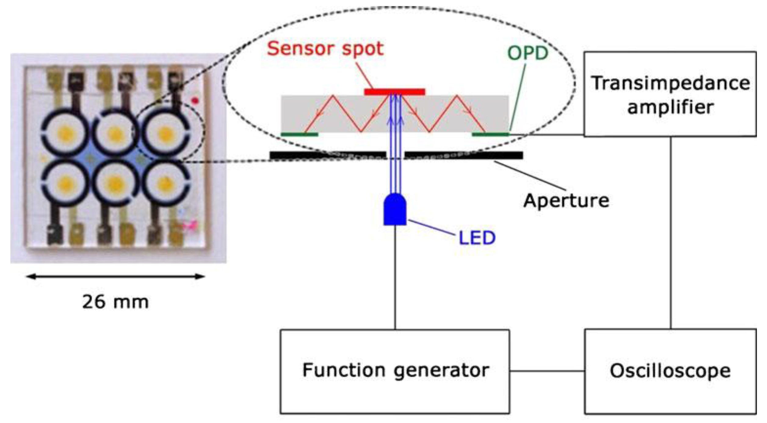
| Multi-analyte conc | PLqabs | film, PDMS channel, pipette | Au/Moo3/CuPc/PTCBI/Bphen/Ag | LEDs (various) w/ aperture | O2, CO2 | 0–20% | [87,88,89,90,91] |
| pH | 5–10 | ||||||
| RIU | n = 1.33–1.43 | ||||||
| Dye conc, immunoassay | CLPL | PDMS channel | ITO/CuPc/C60/BCP/Al | LEDs (various) w/fibre | resorufin | 1–50 μM | [92,93] |
| IgA | 20–120 ng/mL | ||||||
| ITO/CuPc/CuPc:C60/C60/BCP/Al | |||||||
| APnEOs | 2–50 ppb | ||||||
| Immunoassay | CL | sol'n in wells, PDMS channel | ITO/PEDOT:PSS/PCDTBT:PC70BM/LiF/Al | N/A | rhTSH | 30 pg/mL–10 ng/mL | [94,95,96,97] |
| human cortisol | 0.28 - 249 nM | ||||||

4.3. Fully Integrated OLED/OPD Lab-on-a-Chip Systems
| Application | Micro-fluidic | Excitation Source | Detector Details | Analyte | Dynamic Range | Ref. | |
|---|---|---|---|---|---|---|---|
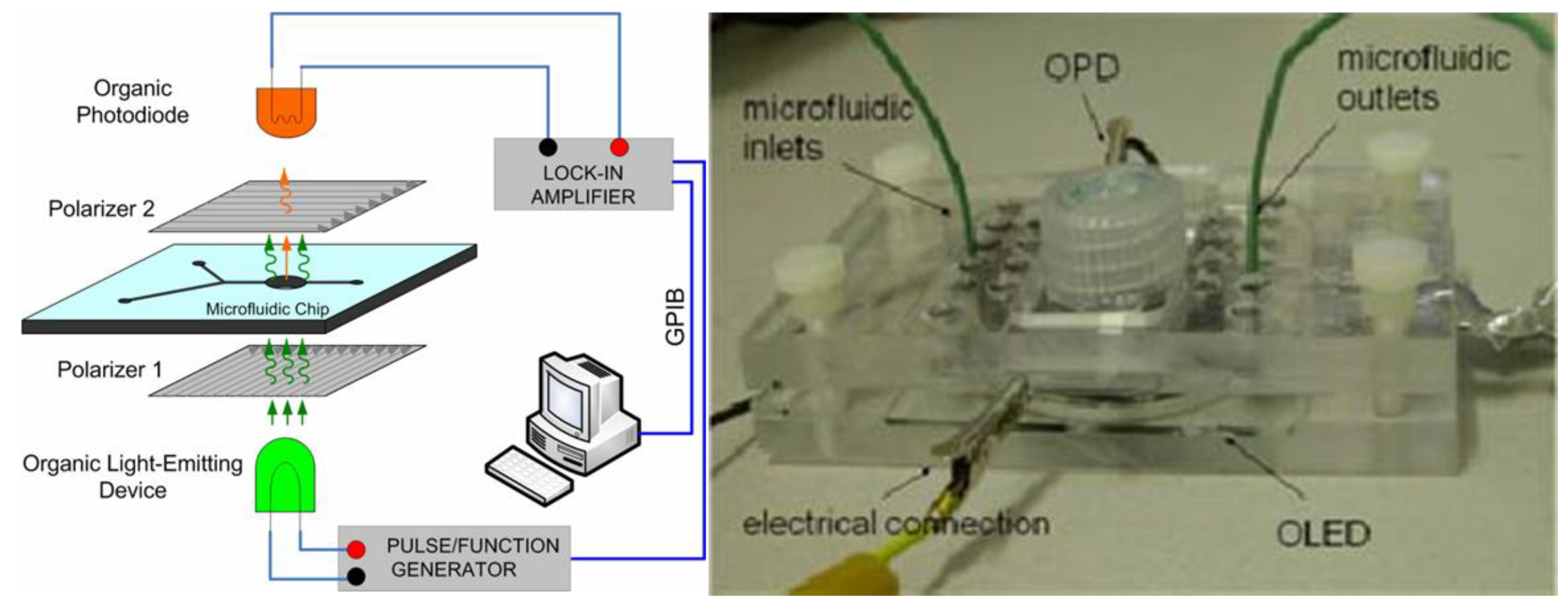
| Dye conc | PL | PDMS channel | ITO/EB390/NPB/Alq3/LiF/Al | ITO/PEDOT:PSS/CuPc/C60/LiF/Al | Rh6G | 0.1 nM–1 mM | [105,106,107,108] |
| fluor-escein | 1 µM–1 mM | ||||||
| Multi-analyte conc | PLq | film (non-MF) | Au/CuPc/NPB/Alq3/LiF/Ag | Au/CuPc/PTCBI/Alq3/Ag | O2 | 0–20% | [109,110] |
| Blue-emitting OLEDs | CO2 | 0–10% | |||||
| pH | 3–9 | ||||||
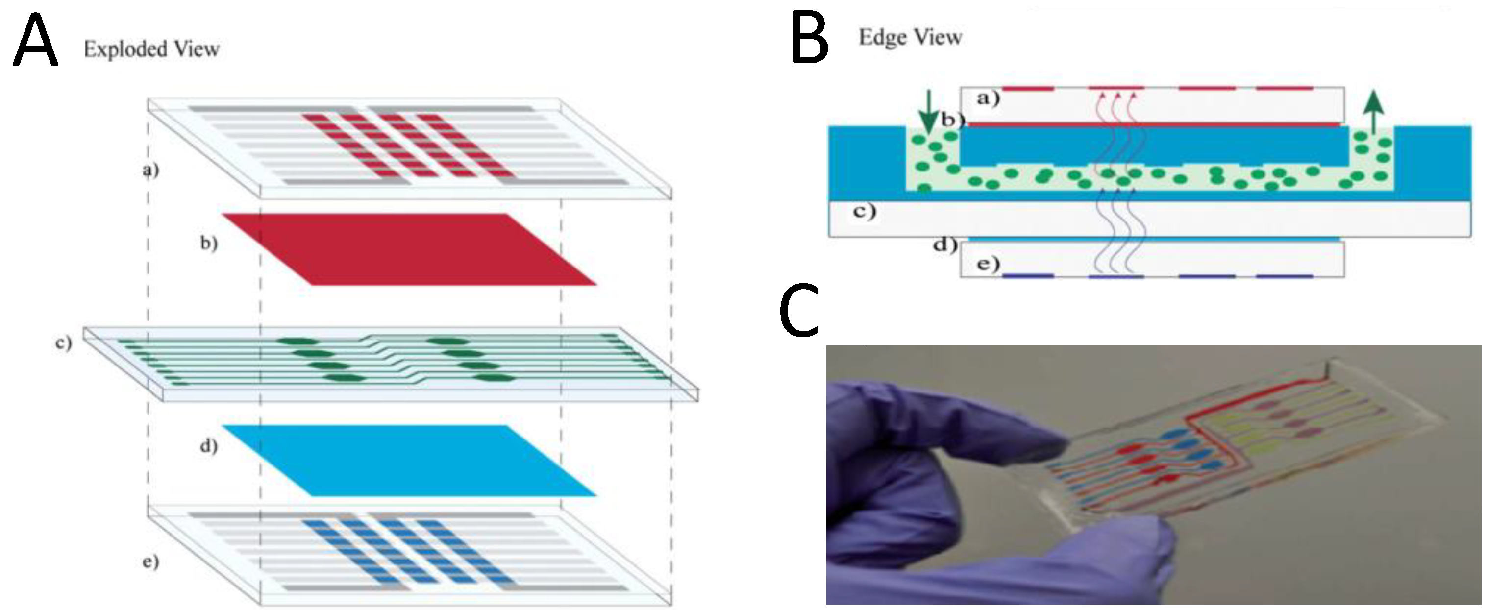
| Multi-analyte conc | PLq | film (non-MF) | ITO/CuPc/NPD/Alq3:C545T/Alq3/LiF/Al | ITO/PEDOT:PSS/P3HT:PCBM/Al | O2 | 0-100% | [111,112] |
| Ag/MoO3/α-NPB/Alq3/LiF/Al | ITO/LiF/CuPc/C70/Bphen/Al | pH | 4–10 | ||||
| Cell counting, herbicide conc | PL | PDMS channel | ITO/NPB/DPVBi/BCP/Alq3/LiF/Al | ITO/PTB3:PCBM/LiF/Al | green algae CC-125 | 2.1E5–3E6 cells/mL | [113] |
| DCMU | 7.5 nM–1.5 µM | ||||||
| Immuno assay, Spectro-scopy | abs | PMMA + tape | ITO/PEDOT:PSS/Ir(mppy)3:PVK:TPD:PBD/Ba/Al | ITO/P3HT:PCBM/Ba/Al w/ etched glass grating | mIgG | N/A | [114] |


5. Conclusions
List of Abbreviations
| Abbreviation | Full Name |
| abs | Full Name |
| Alq3 | tris(quinolinolate) Al |
| a-NPD | N,N'-di(alpha-naphthyl)-N,N'-diphenyl-1,1'-biphenyl-4,4'-diamine |
| APD | avalanche photodiode |
| APnEOs | alkylphenol polyethoxylates |
| BCP | bathocuproine |
| BHJ | bulk heterojunction |
| Bphen | 4,7-diphenyl-1,10-pheranthoroline |
| C545T | coumarin 545T |
| C60 | fullerene |
| CBP | 4,4'-Di( N-carbazolyl)biphenyl |
| CC-125 | chlamydomonas reinhardtii |
| CCD | charge-coupled device |
| CL(q) | chemiluminescence (quenching) |
| CPPO | bis (2-carbopentyloxy-3,5,6-trichlorophenyl) oxalate |
| CuPc | copper phthalocyanine |
| DBR | distributed Bragg reflector |
| DCM | 4-dicyanomethylene-2-methyl-6-( p-dimethylaminostyril)-4H-pyrane |
| DCMU | 3(3,4-dichlorophenyl)-1,1-dimethylurea, Diuron |
| DMAP | 4-dimethylaminopyridine |
| DPVBi | 4,4'-bis(2,2'-diphenylvinyl)-1,1'-biphenyl |
| EL | electroluminescence |
| EP | electrophoretic |
| EQE | external quantum efficiency |
| HPTS | 8-hydroxypyrene-1,3,6-trisulfonic acid |
| IEF | isoelectric focusing |
| Ir(ppy)3 | tris(2-phenylpyridine)iridium |
| IV | current-voltage (measurements) |
| LIF | laser-induced fluorescence |
| LoC | lab-on-a-chip |
| LoD | limit of detection |
| MEH-PPV | poly[2-methoxy-5-(2'-ethylhexyloxy)- p-phenylene vinylene] |
| mIgG | mouse immunoglobulin G |
| mKP | m-Cresol purple |
| NHDF | normal human dermal fibroblasts |
| NPB/NPD | 4,4'-bis[ N-(1-naphthyl)-N-phenylamino]biphenyl |
| OLED | organic light emitting diode |
| OPD | organic photodetector |
| OSC | organic solar cell |
| PBD | 2-(4-biphenyl)-5-(4- t-butylphenyl)-1,3,4-oxadiazole |
| PC70BM | 1-(3-methoxycarbonyl)-propyl-1-phenyl-(6,6)C71 |
| PCBM | 1-(3-methoxycarbonyl)-propyl-1-phenyl-(6,6)C61 |
| PCDTBT | poly [N-9'-heptadecanyl-2,7-carbazole-alt-5,5-(4',7'-di-2-thienyl-2',1',3'-benzothiadiazole)] |
| PDMS | polydimethylsiloxane |
| PDY-132 | Super Yellow |
| PEDOT:PSS | poly(3,4-ethylenedioxythiophene) poly(styrenesulfonate) |
| PF | polyfluorene |
| PL(q) | photoluminescence (quenching) |
| PMT | photomultiplier tube |
| PMMA | poly(methyl methacrylate) |
| PP | polypropylene |
| PPV | poly( p-phenylene vinylene) |
| PTCBI | 3,4,9,10-perylenetetracarboxylic bis-benzimidazole |
| PtOEP | Pt octaethylporphyrin |
| PtTFPP | (II) meso-tetra(pentafluorophenyl)porphine |
| PVK | poly(9-vinylcarbazole) |
| Rh6G | rhodamine 6G |
| RhB | rhodamine B |
| rhTSH | recombinant human thyroid stimulating hormone |
| RIU | refractive index unit |
| Ru(dpp) | tris(4,7-diphenyl-1,10-phenanthroline) Ru chloride |
| SEB | staphylococcal enterotoxin B |
| SNR | signal to noise ratio |
| SPR | surface plasmon resonance |
| TAC | total antioxidant capacity |
| TAMRA | tetramethylrhodamine |
| TOA+OH- | tetraoctylammonium hydroxide |
| µTPD | N,N'-diphenyl-N,N'-di(m-tolyl)-benzidine |
| µc-OLED | microcavity OLED |
Acknowledgments
Conflicts of Interest
References
- Roman, G.T.; Kennedy, R.T. Fully integrated microfluidic separations systems for biochemical analysis. J. Chromatogr. A 2007, 1168, 170–188. [Google Scholar] [CrossRef]
- Yi, C.; Li, C.W.; Ji, S.; Yang, M. Microfluidics technology for manipulation and analysis of biological cells. Anal. Chim. Acta 2006, 560, 1–23. [Google Scholar] [CrossRef]
- Haeberle, S.; Zengerle, R. Microfluidic platforms for lab-on-a-chip applications. Lab Chip 2007, 7, 1094–1110. [Google Scholar] [CrossRef]
- Kajiyama, Y.; Joseph, K.; Kajiyama, K.; Kudo, S.; Aziz, H. Recent Progress on the Vacuum Deposition of OLEDS with Feature Sizes ≤ 20 μm Using a Contact Shadow Mask Patterned in-situ by Laser Ablation. In Organic Light Emitting Materials and Devices XVII, Proceedings of SPIE 8829, San Diego, CA, USA, 25 August 2013; So, F., Adachi, C., Eds.; SPIE International Society for Optical Engineering: Bellingham, WA, USA; p. 882919.
- Kajiyama, Y.; Wang, Q.; Kajiyama, K.; Kudo, S.; Aziz, H. Vacuum Deposition of OLEDS with Feature Sizes ≤ 20um Using a Contact Shadow Mask Patterned in-situ by Laser Ablation. In Proceeding of SID Symposium Digest of Technical Papers, 2012, 1 October 2012; Wiley Online Library: Hoboken, NJ, USA; pp. 1544–1547.
- Mishra, A.; Bäuerle, P. Small molecule organic semiconductors on the move: Promises for future solar energy technology. Angew. Chem. Int. Edit. 2012, 51, 2020–2067. [Google Scholar] [CrossRef]
- Mas-Torrent, M.; Rovira, C. Novel small molecules for organic field-effect transistors: Towards processability and high performance. Chem. Soc. Rev. 2008, 37, 827–838. [Google Scholar] [CrossRef]
- Duan, L.; Hou, L.; Lee, T.-W.; Qiao, J.; Zhang, D.; Dong, G.; Wang, L.; Qiu, Y. Solution processable small molecules for organic light-emitting diodes. J. Mater. Chem. 2010, 20, 6392–6407. [Google Scholar] [CrossRef]
- Tang, C.; VanSlyke, S. Organic electroluminescent diodes. Appl. Phys. Lett. 1987, 51, 913–915. [Google Scholar] [CrossRef]
- Van Slyke, S.; Chen, C.; Tang, C. Organic electroluminescent devices with improved stability. Appl. Phys. Lett. 1996, 69, 2160. [Google Scholar] [CrossRef]
- Peumans, P.; Yakimov, A.; Forrest, S.R. Small molecular weight organic thin-film photodetectors and solar cells. J. Appl. Phys. 2003, 93, 3693–3723. [Google Scholar] [CrossRef]
- Pohl, R.; Montes, V.A.; Shinar, J.; Anzenbacher Jr, P. Red-green-blue emission from tris (5-aryl-8-quinolinolate) al (iii) complexes. J. Org. Chem. 2004, 69, 1723–1725. [Google Scholar] [CrossRef]
- Inganäs, O.; Roman, L.S.; Zhang, F.; Johansson, D.; Andersson, M.; Hummelen, J. Recent progress in thin film organic photodiodes. Synth. Met. 2001, 121, 1525–1528. [Google Scholar]
- Reyes-Reyes, M.; Kim, K.; Carroll, D.L. High-efficiency photovoltaic devices based on annealed poly(3-hexylthiophene) and 1-(3-methoxycarbonyl)-propyl-1-phenyl-(6,6)c-61 blends. Appl. Phys. Lett. 2005, 87, 083506. [Google Scholar]
- Williams, G.; Wang, Q.; Aziz, H. The photo-stability of polymer solar cells: Contact photo-degradation and the benefits of interfacial layers. Adv. Funct. Mater. 2012, 23, 2239–2247. [Google Scholar] [CrossRef]
- Williams, G.; Aziz, H. Insights into Electron and Hole Extraction Layers for Upright and Inverted Vacuum-Deposited Small Molecule Organic Solar Cells, Proceeding of Organic Photovoltaics XIV, San Diego, CA, USA, 17 October 2013; SPIE International Society for Optical Engineering: Bellingham, WA, USA, 2013; p. 88301.
- Williams, G.; Aziz, H. The effect of charge extraction layers on the photo-stability of vacuum-deposited versus solution-coated organic solar cells. Org. Electron. 2013, 15, 47–56. [Google Scholar] [CrossRef]
- Xue, J.G.; Uchida, S.; Rand, B.P.; Forrest, S.R. Asymmetric tandem organic photovoltaic cells with hybrid planar-mixed molecular heterojunctions. Appl. Phys. Lett. 2004, 85, 5757–5759. [Google Scholar] [CrossRef]
- Ratcliff, E.L.; Garcia, A.; Paniagua, S.A.; Cowan, S.R.; Giordano, A.J.; Ginley, D.S.; Marder, S.R.; Berry, J.J.; Olson, D.C. Investigating the influence of interfacial contact properties on open circuit voltages in organic photovoltaic performance: Work function versus selectivity. Adv. Energy Mater. 2013, 3, 647–656. [Google Scholar]
- Reineke, S.; Baldo, M.A. Recent progress in the understanding of exciton dynamics within phosphorescent oleds. Phys. Status Solidi 2012, 209, 2341–2353. [Google Scholar]
- Birnstock, J.; Lux, A.; Ammann, M.; Wellmann, P.; Hofmann, M.; Stübinger, T. 64.4: Novel Materials and Structures for Highly-Efficient, Temperature-Stable, and Long-Living am OLED Displays. SIDInt. Symp. Dig. Tech. Pap. 2006, 37, 1866–1869. [Google Scholar] [CrossRef]
- Uhrich, C.L.; Schwartz, G.; Maennig, B.; Gnehr, W.M.; Sonntag, S.; Erfurth, O.; Wollrab, E.; Walzer, K.; Foerster, J.; Weiss, A. Efficient and Long-Term Stable Organic Vacuum Deposited Tandem Solar Cells, Proceedings of SPIE Photonics Europe, Brussels, Belgium, 19 May 2010; International Society for Optics and Photonics: Bellingham, WA, USA, 2010; p. 77220G.
- Figeys, D.; Pinto, D. Lab-on-a-chip: A revolution in biological and medical sciences. Anal. Chem. 2000, 72, 330–335. [Google Scholar]
- Abgrall, P.; Gue, A. Lab-on-chip technologies: Making a microfluidic network and coupling it into a complete microsystem—A review. J. Micromech. Microeng. 2007, 17, R15. [Google Scholar] [CrossRef]
- Mark, D.; Haeberle, S.; Roth, G.; Von Stetten, F.; Zengerle, R. Microfluidic lab-on-a-chip platforms: Requirements, characteristics and applications. Chem. Soc. Rev. 2010, 39, 1153–1182. [Google Scholar] [CrossRef]
- Erickson, D.; Li, D. Integrated microfluidic devices. Anal. Chim. Acta 2004, 507, 11–26. [Google Scholar] [CrossRef]
- Hunt, H.C.; Wilkinson, J.S. Optofluidic integration for microanalysis. Microfluid. Nanofluid. 2008, 4, 53–79. [Google Scholar]
- Liu, R.; Ishimatsu, R.; Nakano, K.; Imato, T. Optical sensing systems suitable for flow analysis on microchips. J. Flow Injection Anal. 2013, 30, 15–20. [Google Scholar]
- Capitán-Vallvey, L.F.; Palma, A.J. Recent developments in handheld and portable optosensing—A review. Anal. Chim. Acta 2011, 696, 27–46. [Google Scholar] [CrossRef]
- Gai, H.; Li, Y.; Yeung, E.S. Optical Detection Systems on Microfluidic Chips. In Microfluidics; Springer: Heidelberg, Germany, 2011; pp. 171–201. [Google Scholar]
- Yu, L.; Shen, Z.; Mo, J.; Dong, X.; Qin, J.; Lin, B. Microfluidic chip-based cell electrophoresis with multipoint laser-induced fluorescence detection system. Electrophoresis 2007, 28, 4741–4747. [Google Scholar] [CrossRef]
- Fu, J.L.; Fang, Q.; Zhang, T.; Jin, X.H.; Fang, Z.L. Laser-induced fluorescence detection system for microfluidic chips based on an orthogonal optical arrangement. Anal. Chem. 2006, 78, 3827–3834. [Google Scholar] [CrossRef]
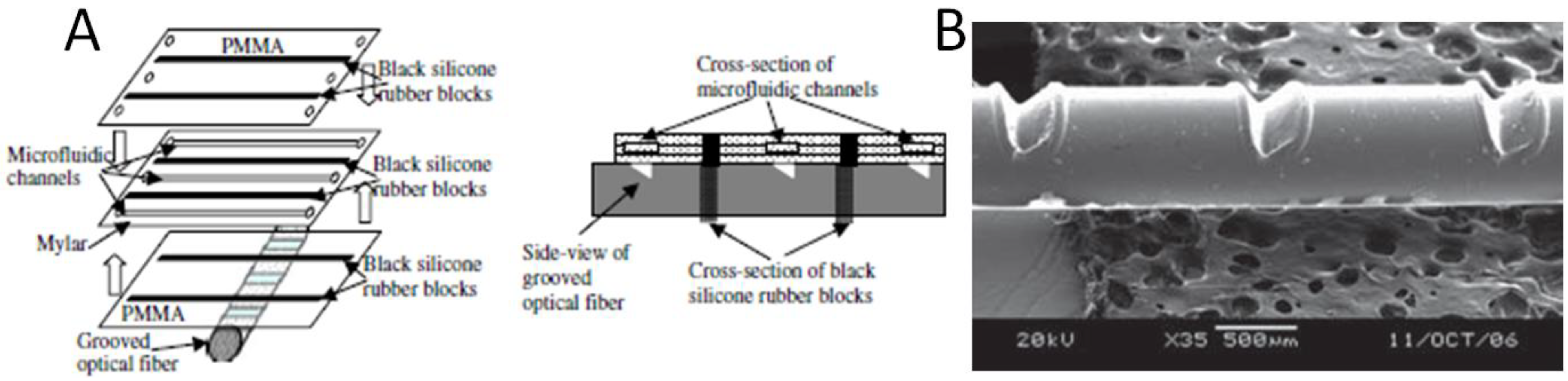
- Irawan, R.; Tjin, S.C.; Fang, X.; Fu, C.Y. Integration of optical fiber light guide, fluorescence detection system, and multichannel disposable microfluidic chip. Biomed. Microdevices 2007, 9, 413–419. [Google Scholar] [CrossRef]
- Gao, J.; Yin, X.F.; Fang, Z.L. Integration of single cell injection, cell lysis, separation and detection of intracellular constituents on a microfluidic chip. Lab Chip 2003, 4, 47–52. [Google Scholar]
- Roulet, J.C.; Völkel, R.; Herzig, H.P.; Verpoorte, E.; de Rooij, N.F.; Dändliker, R. Performance of an integrated microoptical system for fluorescence detection in microfluidic systems. Anal. Chem. 2002, 74, 3400–3407. [Google Scholar] [CrossRef]
- Bliss, C.L.; McMullin, J.N.; Backhouse, C.J. Integrated wavelength-selective optical waveguides for microfluidic-based laser-induced fluorescence detection. Lab Chip 2008, 8, 143–151. [Google Scholar] [CrossRef]
- Monat, C.; Domachuk, P.; Eggleton, B. Integrated optofluidics: A new river of light. Nat. Photonics 2007, 1, 106–114. [Google Scholar] [CrossRef]
- Schmidt, H.; Hawkins, A.R. The photonic integration of non-solid media using optofluidics. Nat. Photonics 2011, 5, 598–604. [Google Scholar] [CrossRef]
- Gersborg-Hansen, M.; Kristensen, A. Tunability of optofluidic distributed feedback dye lasers. Opt. Express 2007, 15, 137–142. [Google Scholar] [CrossRef]
- Chabinyc, M.L.; Chiu, D.T.; McDonald, J.C.; Stroock, A.D.; Christian, J.F.; Karger, A.M.; Whitesides, G.M. An integrated fluorescence detection system in poly (dimethylsiloxane) for microfluidic applications. Anal. Chem. 2001, 73, 4491–4498. [Google Scholar]
- Irawan, R.; Chuan, T.S.; Yaw, F.C. Integration of a fluorescence detection system and a laminate-based disposable microfluidic chip. Microw. Opt. Technol. Lett. 2005, 45, 456–460. [Google Scholar] [CrossRef]
- Irawan, R.; Tjin, S.C. Detection of fluorescence generated in microfluidic channel using in-fiber grooves and in-fiber microchannel sensors. Meth. Mol. Biol. 2009, 503, 403. [Google Scholar] [CrossRef]
- Seo, J.; Lee, L.P. Disposable integrated microfluidics with self-aligned planar microlenses. Sensor. Actuat. B 2004, 99, 615–622. [Google Scholar] [CrossRef]
- Mazurczyk, R.; Vieillard, J.; Bouchard, A.; Hannes, B.; Krawczyk, S. A novel concept of the integrated fluorescence detection system and its application in a lab-on-a-chip microdevice. Sensor. Actuat. B 2006, 118, 11–19. [Google Scholar] [CrossRef]
- Novak, L.; Neuzil, P.; Pipper, J.; Zhang, Y.; Lee, S. An integrated fluorescence detection system for lab-on-a-chip applications. Lab Chip 2007, 7, 27–29. [Google Scholar] [CrossRef]
- Ryu, G.; Huang, J.; Hofmann, O.; Walshe, C.A.; Sze, J.Y.Y.; McClean, G.D.; Mosley, A.; Rattle, S.J.; Bradley, D.D.C. Highly sensitive fluorescence detection system for microfluidic lab-on-a-chip. Lab Chip 2011, 11, 1664–1670. [Google Scholar] [CrossRef]
- Kamei, T.; Paegel, B.M.; Scherer, J.R.; Skelley, A.M.; Street, R.A.; Mathies, R.A. Integrated hydrogenated amorphous Si photodiode detector for microfluidic bioanalytical devices. Anal. Chem. 2003, 75, 5300–5305. [Google Scholar] [CrossRef]
- Kamei, T.; Wada, T. Contact-lens type of micromachined hydrogenated amorphous Si fluorescence detector coupled with microfluidic electrophoresis devices. Appl. Phys. Lett. 2006, 89, 114101. [Google Scholar] [CrossRef]
- Lin, C.L.; Lin, H.W.; Wu, C.C. Examining microcavity organic light-emitting devices having two metal mirrors. Appl. Phys. Lett. 2005, 87, 021101. [Google Scholar] [CrossRef]
- Peng, H.J.; Sun, J.X.; Zhu, X.L.; Yu, X.M.; Wong, M.; Kwok, H.S. High-efficiency microcavity top-emitting organic light-emitting diodes using silver anode. Appl. Phys. Lett. 2006, 88, 073517. [Google Scholar] [CrossRef]
- Dodabalapur, A.; Rothberg, L.J.; Jordan, R.H.; Miller, T.M.; Slusher, R.E.; Phillips, J.M. Physics and applications of organic microcavity light emitting diodes. J. Appl. Phys. 1996, 80, 6954–6964. [Google Scholar] [CrossRef]
- Tessler, N.; Harrison, N.T.; Friend, R.H. High peak brightness polymer light-emitting diodes. Adv. Mater. 1998, 10, 64–68. [Google Scholar] [CrossRef]
- Shinar, J.; Shinar, R. Organic light-emitting devices (OLEDS) and oled-based chemical and biological sensors: An overview. J. Phys. D 2008, 41, 133001. [Google Scholar] [CrossRef]
- Liu, R.; Cai, Y.; Park, J.M.; Ho, K.M.; Shinar, J.; Shinar, R. Organic light-emitting diode sensing platform: Challenges and solutions. Adv. Funct. Mat. 2011, 21, 4744–4753. [Google Scholar] [CrossRef]
- Choudhury, B.; Shinar, R.; Shinar, J. Glucose biosensors based on organic light-emitting devices structurally integrated with a luminescent sensing element. J. Appl. Phys. 2004, 96, 2949–2954. [Google Scholar] [CrossRef]
- Cai, Y.; Shinar, R.; Zhou, Z.; Shinar, J. Multianalyte sensor array based on an organic light emitting diode platform. Sensor. Actuat. B 2008, 134, 727–735. [Google Scholar] [CrossRef]
- Cai, Y.; Smith, A.; Shinar, J.; Shinar, R. Data analysis and aging in phosphorescent oxygen-based sensors. Sensor. Actuat. B 2010, 146, 14–22. [Google Scholar] [CrossRef]
- Vohra, V.; Giovanella, U.; Tubino, R.; Murata, H.; Botta, C. Electroluminescence from conjugated polymer electrospun nanofibers in solution processable organic light-emitting diodes. ACS Nano 2011, 5, 5572–5578. [Google Scholar]
- Pagliara, S.; Camposeo, A.; Polini, A.; Cingolani, R.; Pisignano, D. Electrospun light-emitting nanofibers as excitation source in microfluidic devices. Lab Chip 2009, 9, 2851–2856. [Google Scholar] [CrossRef]
- Aziz, H.; Liew, Y.F.; Grandin, H.M.; Popovic, Z.D. Reduced reflectance cathode for organic light-emitting devices using metalorganic mixtures. Appl. Phys. Lett. 2003, 83, 186–188. [Google Scholar] [CrossRef]
- Wong, F.; Fung, M.; Jiang, X.; Lee, C.; Lee, S. Non-reflective black cathode in organic light-emitting diode. Thin Solid Films 2004, 446, 143–146. [Google Scholar] [CrossRef]
- Vannahme, C.; Klinkhammer, S.; Lemmer, U.; Mappes, T. Plastic lab-on-a-chip for fluorescence excitation with integrated organic semiconductor lasers. Opt. Express 2011, 19, 8179–8186. [Google Scholar] [CrossRef]
- Camou, S.; Kitamura, M.; Gouy, J.-P.; Fujita, H.; Arakawa, Y.; Fujii, T. Organic Light-Emitting Device as a Fluorescence Spectroscopy Light Source: One Step toward the Lab-on-a-Chip Device. In Applications of Photonic Technology 5, Proceedings of SPIE 4833, Quebec City, Quebec, Canada, 2 June 2002; Lessard, R., Lampropoulos, G., Schinn, G., Eds.; SPIE International Society for Optical Engineering: Bellingham, WA, USA, 2003; pp. 1–8. [Google Scholar]
- Camou, S.; Kitamura, M.; Arakawa, Y.; Fujii, T. Integration of Oled Light Source And Optical Fibers on a PDMS Based Microfluidic Device for on-Chip Fluorescence Detection. In 7th International Conference on Miniaturized Chemical and Biochemical Analysis Systems, Proceedings of Micro Total Analysis Systems 2003, Squaw Valley, CA, USA, 5–9 October 2003; Northrup, M., Jensen, K., Harrison, D., Eds.; Transducers Research Foundation: Cleveland Heights, OH, USA, 2003; pp. 383–386. [Google Scholar]
- Vengasandra, S.; Cai, Y.K.; Grewell, D.; Shinar, J.; Shinar, R. Polypropylene cd-organic light-emitting diode biosensing platform. Lab Chip 2010, 10, 1051–1056. [Google Scholar]
- Edel, J.B.; Beard, N.P.; Hofmann, O.; Bradley, D.D.C. Thin-film polymer light emitting diodes as integrated excitation sources for microscale capillary electrophoresis. Lab Chip 2004, 4, 136–140. [Google Scholar] [CrossRef]
- Hofmann, O.; Wang, X.H.; deMello, J.C.; Bradley, D.D.C.; deMello, A.J. Towards microalbuminuria determination on a disposable diagnostic microchip with integrated fluorescence detection based on thin-film organic light emitting diodes. Lab Chip 2005, 5, 863–868. [Google Scholar] [CrossRef]
- Ren, K.N.; Liang, Q.L.; Yao, B.; Luo, G.O.; Wang, L.D.; Gao, Y.; Wang, Y.M.; Qiu, Y. Whole column fluorescence imaging on a microchip by using a programmed organic light emitting diode array as a spatial-scanning light source and a single photomultiplier tube as detector. Lab Chip 2007, 7, 1574–1580. [Google Scholar] [CrossRef]
- Yao, B.; Luo, G.; Wang, L.; Gao, Y.; Lei, G.; Ren, K.; Chen, L.; Wang, Y.; Hu, Y.; Qiu, Y. A microfluidic device using a green organic light emitting diode as an integrated excitation source. Lab Chip 2005, 5, 1041–1047. [Google Scholar] [CrossRef]
- Yao, B.; Yang, H.; Liang, Q.; Luo, G.; Wang, L.; Ren, K.; Gao, Y.; Wang, Y.; Qiu, Y. High-speed, whole-column fluorescence imaging detection for isoelectric focusing on a microchip using an organic light emitting diode as light source. Anal. Chem. 2006, 78, 5845–5850. [Google Scholar] [CrossRef]
- Kim, Y.H.; Shin, K.S.; Kang, J.Y.; Yang, E.G.; Paek, K.K.; Seo, D.S.; Ju, B.K. Poly(dimethylsiloxane)-based packaging technique for microchip fluorescence detection system applications. J. Microelectromech. Syst. 2006, 15, 1152–1158. [Google Scholar]
- Shin, K.S.; Kim, Y.H.; Paek, K.K.; Park, J.H.; Yang, E.G.; Kim, T.S.; Kang, J.Y.; Ju, B.K. Characterization of an integrated, fluorescence-detection hybrid device with photodiode and organic light-emitting diode. IEEE Electron Device Lett. 2006, 27, 746–748. [Google Scholar] [CrossRef]
- Devabhaktuni, S.; Prasad, S. Nanotextured organic light emitting diode based chemical sensor. J. Nanosci. Nanotechnol. 2009, 9, 6299–6306. [Google Scholar] [CrossRef]
- Scholer, L.; Seibel, K.; Panczyk, K.; Bohm, M. An integrated pled—A light source for application specific lab-on-microchips (ALM). Microelectron. Eng. 2009, 86, 1502–1504. [Google Scholar] [CrossRef]
- Nakajima, H.; Okuma, Y.; Morioka, K.; Miyake, M.; Hemmi, A.; Tobita, T.; Yahiro, M.; Yokoyama, D.; Adachi, C.; Soh, N.; et al. An integrated enzyme-linked immunosorbent assay system with an organic light-emitting diode and a charge-coupled device for fluorescence detection. J. Sep. Sci. 2011, 34, 2906–2912. [Google Scholar] [CrossRef]
- Marcello, A.; Sblattero, D.; Cioarec, C.; Maiuri, P.; Melpignano, P. A deep-blue oled-based biochip for protein microarray fluorescence detection. Biosens. Bioelectron. 2013, 46, 44–47. [Google Scholar] [CrossRef]
- Wu, X.Z.; Sze, N.S.K.; Pawliszyn, J. Miniaturization of capillary isoelectric focusing. Electrophoresis 2001, 22, 3968–3971. [Google Scholar] [CrossRef]
- Cui, H.; Horiuchi, K.; Dutta, P.; Cornelius, F. Isoelectric focusing in a poly (dimethylsiloxane) microfluidic chip. Anal. Chem. 2005, 77, 1303–1309. [Google Scholar] [CrossRef]
- Helander, M.; Wang, Z.; Qiu, J.; Greiner, M.; Puzzo, D.; Liu, Z.; Lu, Z. Chlorinated indium tin oxide electrodes with high work function for organic device compatibility. Science 2011, 332, 944–947. [Google Scholar] [CrossRef]
- Hofmann, O.; Miller, P.; Sullivan, P.; Jones, T.S.; demello, J.C.; Bradley, D.D.C.; demello, A.J. Thin-film organic photodiodes as integrated detectors for microscale chemiluminescence assays. Sensor. Actuat. B 2005, 106, 878–884. [Google Scholar] [CrossRef]
- Wang, X.; Amatatongchai, M.; Nacapricha, D.; Hofmann, O.; de Mello, J.C.; Bradley, D.D.C.; de Mello, A.J. Thin-film organic photodiodes for integrated on-chip chemiluminescence detection–application to antioxidant capacity screening. Sensor. Actuat. B 2009, 140, 643–648. [Google Scholar] [CrossRef]
- Wang, X.; Hofmann, O.; Das, R.; Barrett, E.M.; Bradley, D.D.C. Integrated thin-film polymer/fullerene photodetectors for on-chip microfluidic chemiluminescence detection. Lab Chip 2006, 7, 58–63. [Google Scholar]
- Banerjee, A.; Pais, A.; Papautsky, I.; Klotzkin, D. A polarization isolation method for high-sensitivity, low-cost on-chip fluorescence detection for microfluidic lab-on-a-chip. IEEE Sens. J. 2008, 8, 621–627. [Google Scholar] [CrossRef]
- Wojciechowski, J.R.; Shriver-Lake, L.C.; Yamaguchi, M.Y.; Füreder, E.; Pieler, R.; Schamesberger, M.; Winder, C.; Prall, H.J.; Sonnleitner, M.; Ligler, F.S. Organic photodiodes for biosensor miniaturization. Anal. Chem. 2009, 81, 3455–3461. [Google Scholar] [CrossRef]
- Charwat, V.; Muellner, P.; Hainberger, R.; Purtscher, M.; Ertl, P.; Tedde, S.; Hayden, O. Monitoring Light Scattering Characteristics of Adherent Cell Cultures Using a Lab-on-a-Chip. In Information Photonics (IP), Proceedings of the 2011 ICO International Conference, Ottawa, Canada, 18–20 May 2011; IEEE: Piscataway, NJ, USA, 2011; pp. 1–2. [Google Scholar]
- Charwat, V.; Purtscher, M.; Tedde, S.F.; Hayden, O.; Ertl, P. Standardization of microfluidic cell cultures using integrated organic photodiodes and electrode arrays. Lab Chip 2013, 13, 785–797. [Google Scholar] [CrossRef]
- Abel, T.; Sagmeister, M.; Lamprecht, B.; Kraker, E.; Kostler, S.; Ungerbock, B.; Mayr, T. Filter-free integrated sensor array based on luminescence and absorbance measurements using ring-shaped organic photodiodes. Anal. Bioanal. Chem. 2012, 404, 2841–2849. [Google Scholar] [CrossRef]
- Lamprecht, B.; Sagmeister, M.; Kraker, E.; Hartmann, P.; Jakopic, G.; Köstler, S.; Ditlbacher, H.; Galler, N.; Krenn, J.; Ungerböck, B. Integrated Waveguide Sensor Platform Utilizing Organic Photodiodes. In Plasmonics in Biology and Medicine IX, Proceedings of SPIE 8234, San Francisco, CA, USA, 21 January 2012; Vo-Dinh, T., Lakowicz, J., Eds.; SPIE International Society for Optical Engineering: Bellingham, WA, USA, 2012; p. 82341. [Google Scholar]
- Lamprecht, B.; Tschepp, A.; Cajlakovic, M.; Sagmeister, M.; Ribitsch, V.; Kostler, S. A luminescence lifetime-based capillary oxygen sensor utilizing monolithically integrated organic photodiodes. Analyst 2013, 138, 5875–5878. [Google Scholar] [CrossRef]
- Sagmeister, M.; Lamprecht, B.; Kraker, E.; Haase, A.; Jakopic, G.; Kostler, S.; Ditlbacher, H.; Galler, N.; Abel, T.; Mayr, T. Integrated Organic Optical Sensor Arrays Based on Ring-Shaped Organic Photodiodes. In Organic Semiconductors in Sensors and Bioelectronics IV, Proceedings of SPIE 8118, San Diego, CA, USA, 21 August 2011; Shinar, R., Kymissis, I., Eds.; SPIE International Society for Optical Engineering: Bellingham, WA, USA, 2011; p. 811805. [Google Scholar]
- Sagmeister, M.; Tschepp, A.; Kraker, E.; Abel, T.; Lamprecht, B.; Mayr, T.; Kostler, S. Enabling luminescence decay time-based sensing using integrated organic photodiodes. Anal. Bioanal Chem. 2013, 405, 5975–5982. [Google Scholar]
- Ishimatsu, R.; Naruse, A.; Liu, R.; Nakano, K.; Yahiro, M.; Adachi, C.; Imato, T. An organic thin film photodiode as a portable photodetector for the detection of alkylphenol polyethoxylates by a flow fluorescence-immunoassay on magnetic microbeads in a microchannel. Talanta 2013, 117, 139–145. [Google Scholar] [CrossRef]
- Miyake, M.; Nakajima, H.; Hemmi, A.; Yahiro, M.; Adachi, C.; Soh, N.; Ishimatsu, R.; Nakano, K.; Uchiyama, K.; Imato, T. Performance of an organic photodiode as an optical defector and its application to fluorometric flow-immunoassay for iga. Talanta 2012, 96, 132–139. [Google Scholar] [CrossRef]
- Pires, N.M.; Dong, T. Polycarbazole-Based Organic Photodiodes for highly Sensitive Chemiluminescent Immunoassays. In 35th Annual International Conference of the IEEE EMBS, Proceedings of EMBC 2013, Osaka, Japan, 3–7 July 2013; IEEE: Piscataway, NJ, USA, 2013; pp. 1700–1703. [Google Scholar]
- Pires, N.M.; Dong, T. Detection of Stress Hormones by a Microfluidic-Integrated Polycarbazole/Fullerene Photodetector. In 35th Annual International Conference of the IEEE EMBS, Proceedings of EMBC 2013, Osaka, Japan, 3–7 July 2013; IEEE: Piscataway, NJ, USA, 2013; pp. 4470–4473. [Google Scholar]
- Pires, N.M.M.; Dong, T.; Hanke, U.; Hoivik, N. Integrated optical microfluidic biosensor using a polycarbazole photodetector for point-of-care detection of hormonal compounds. J. Biomed. Opt. 2013, 18, 097001. [Google Scholar] [CrossRef]
- Pires, N.M.M.; Dong, T. Microfluidic biosensor array with integrated poly (2,7-carbazole)/fullerene-based photodiodes for rapid multiplexed detection of pathogens. Sensors 2013, 13, 15898–15911. [Google Scholar] [CrossRef]
- Hofmann, O.; Wang, X.; Cornwell, A.; Beecher, S.; Raja, A.; Bradley, D.D.C. Monolithically integrated dye-doped pdms long-pass filters for disposable on-chip fluorescence detection. Lab Chip 2006, 6, 981–987. [Google Scholar] [CrossRef]
- Jorgensen, A.M.; Mogensen, K.B.; Kutter, J.P.; Geschke, O. A biochemical microdevice with an integrated chemiluminescence detector. Sensor. Actuat. B 2003, 90, 15–21. [Google Scholar] [CrossRef]
- Blouin, N.; Michaud, A.; Leclerc, M. A low-bandgap poly (2,7-carbazole) derivative for use in high-performance solar cells. Adv. Mater. 2007, 19, 2295–2300. [Google Scholar] [CrossRef]
- Park, S.H.; Roy, A.; Beaupré, S.; Cho, S.; Coates, N.; Moon, J.S.; Moses, D.; Leclerc, M.; Lee, K.; Heeger, A.J. Bulk heterojunction solar cells with internal quantum efficiency approaching 100%. Nat. Photonics 2009, 3, 297–302. [Google Scholar] [CrossRef]
- Ratcliff, E.L.; Veneman, P.A.; Simmonds, A.; Zacher, B.; Huebner, D.; Saavedra, S.S.; Armstrong, N.R. A planar, chip-based, dual-beam refractometer using an integrated organic light-emitting diode (OLED) light source and organic photovoltaic (OPV) detectors. Anal. Chem. 2010, 82, 2734–2742. [Google Scholar] [CrossRef]
- Krishnaswamy, N.; Srinivas, T.; Rao, G.M. Analysis of Integrated Optofluidic Lab-on-a-Chip Fluorescence Biosensor Based on Transmittance of Light Through a Fluidic Gap. In 33rd Annual International Conference of the IEEE EMBS, Proceedings of EMBC 2011, Boston, MA, USA, 30 August –3 September 2011; IEEE: Piscataway, NJ, USA, 2011; pp. 30–34. [Google Scholar]
- Krishnaswamy, N.; Srinivas, T.; Rao, G.M.; Varma, M.M. Analysis of integrated optofluidic lab-on-a-chip sensor based on refractive index and absorbance sensing. IEEE Sens. J. 2013, 13, 1730–1741. [Google Scholar] [CrossRef]
- Banerjee, A.; Shuai, Y.; Dixit, R.; Papautsky, I.; Klotzkin, D. Concentration dependence of fluorescence signal in a microfluidic fluorescence detector. J. Lumines. 2010, 130, 1095–1100. [Google Scholar]
- Banerjee, A.; Shuai, Y.; Klotzkin, D.; Papautsky, I. High-Sensitivity Mems Based on-Chip Fluorescence Detection System: Measurement and Analysis of Ultimate Sensitivity Limits. In 2008 17th Biennial University/Government/Industry Micro-Nano Symposium, Proceedings of the UGIM 2008 Symposium, Louisville, KY, USA, 13–16 July 2008; IEEE: Piscataway, NJ, USA; pp. 177–182.
- Pais, A.; Banerjee, A.; Klotzkin, D.; Papautsky, I. High-sensitivity, disposable lab-on-a-chip with thin-film organic electronics for fluorescence detection. Lab Chip 2008, 8, 794–800. [Google Scholar] [CrossRef]
- Shuai, Y.; Banerjee, A.; Klotzkin, D.; Papautsky, I. On-Chip Fluorescence Detection with Organic Thin Film Devices for Disposable Lab-on-a-Chip Sensors. In IEEE Sensors 2008, Proceedings of the Seventh IEEE Sensors Conference 2008, Lecce, Italy, 26–29 October 2008; IEEE: Piscataway, NJ, USA, 2008; pp. 122–125. [Google Scholar]
- Kraker, E.; Haase, A.; Lamprecht, B.; Jakopic, G.; Konrad, C.; Kostler, S. Integrated organic electronic based optochemical sensors using polarization filters. Appl. Phys. Lett. 2008, 92, 033302. [Google Scholar] [CrossRef]
- Mayr, T.; Abel, T.; Kraker, E.; Köstler, S.; Haase, A.; Konrad, C.; Tscherner, M.; Lamprecht, B. An optical sensor array on a flexible substrate with integrated organic opto-electric devices. Procedia Engineer. 2010, 5, 1005–1008. [Google Scholar] [CrossRef]
- Liu, R.; Xiao, T.; Cui, W.; Shinar, J.; Shinar, R. Multiple approaches for enhancing all-organic electronics photoluminescent sensors: Simultaneous oxygen and pH monitoring. Anal. Chim. Acta 2013, 778, 70–78. [Google Scholar] [CrossRef]
- Nalwa, K.S.; Cai, Y.; Thoeming, A.L.; Shinar, J.; Shinar, R.; Chaudhary, S. Polythiophene-fullerene based photodetectors: Tuning of spectral response and application in photoluminescence based (bio) chemical sensors. Adv. Mater. 2010, 22, 4157–4161. [Google Scholar] [CrossRef]
- Lefèvre, F.; Chalifour, A.; Yu, L.; Chodavarapu, V.; Juneau, P.; Izquierdo, R. Algal fluorescence sensor integrated into a microfluidic chip for water pollutant detection. Lab Chip 2011, 12, 787–793. [Google Scholar]
- Ramuz, M.; Leuenberger, D.; Burgi, L. Optical biosensors based on integrated polymer light source and polymer photodiode. J. Polym. Sci. Pt. B 2011, 49, 80–87. [Google Scholar] [CrossRef]
- Liang, Y.Y.; Feng, D.Q.; Wu, Y.; Tsai, S.T.; Li, G.; Ray, C.; Yu, L.P. Highly efficient solar cell polymers developed via fine-tuning of structural and electronic properties. J. Am. Chem. Soc. 2009, 131, 7792–7799. [Google Scholar]
- Liang, Y.; Xu, Z.; Xia, J.; Tsai, S.; Wu, Y.; Li, G.; Ray, C.; Yu, L. For the bright future—Bulk heterojunction polymer solar cells with power conversion efficiency of 7.4%. Adv. Mater. 2010, 22, E135–E138. [Google Scholar] [CrossRef]
© 2014 by the authors; licensee MDPI, Basel, Switzerland. This article is an open access article distributed under the terms and conditions of the Creative Commons Attribution license (http://creativecommons.org/licenses/by/3.0/).
Share and Cite
Williams, G.; Backhouse, C.; Aziz, H. Integration of Organic Light Emitting Diodes and Organic Photodetectors for Lab-on-a-Chip Bio-Detection Systems. Electronics 2014, 3, 43-75. https://doi.org/10.3390/electronics3010043
Williams G, Backhouse C, Aziz H. Integration of Organic Light Emitting Diodes and Organic Photodetectors for Lab-on-a-Chip Bio-Detection Systems. Electronics. 2014; 3(1):43-75. https://doi.org/10.3390/electronics3010043
Chicago/Turabian StyleWilliams, Graeme, Christopher Backhouse, and Hany Aziz. 2014. "Integration of Organic Light Emitting Diodes and Organic Photodetectors for Lab-on-a-Chip Bio-Detection Systems" Electronics 3, no. 1: 43-75. https://doi.org/10.3390/electronics3010043
APA StyleWilliams, G., Backhouse, C., & Aziz, H. (2014). Integration of Organic Light Emitting Diodes and Organic Photodetectors for Lab-on-a-Chip Bio-Detection Systems. Electronics, 3(1), 43-75. https://doi.org/10.3390/electronics3010043