
Li-Ion Battery Immersed Heat Pipe Cooling Technology for Electric Vehicles


Applied Thermal Engineering Lab., School of Mechanical Engineering, Chungbuk National University, 1 Chungdae-ro, Cheongju 28644, Republic of Korea
*
Author to whom correspondence should be addressed.
†
These authors contributed equally to this work.
Electronics 2023, 12(24), 4931; https://doi.org/10.3390/electronics12244931
Submission received: 5 November 2023
/
Revised: 3 December 2023
/
Accepted: 6 December 2023
/
Published: 8 December 2023
(This article belongs to the Special Issue Electro-Thermal Modelling, Status Estimation and Thermal Management of Electric Vehicles)
Abstract
:Lithium-ion batteries, crucial in powering Battery Electric Vehicles (BEVs), face critical challenges in maintaining safety and efficiency. The quest for an effective Battery Thermal Management System (BTMS) arises from critical concerns over the safety and efficiency of lithium-ion batteries, particularly in Battery Electric Vehicles (BEVs). This study introduces a pioneering BTMS solution merging a two-phase immersion cooling system with heat pipes. Notably, the integration of NovecTM 649 as the dielectric fluid substantially mitigates thermal runaway-induced fire risks without requiring an additional power source. Comprehensive 1-D modeling, validated against AMESim (Advanced Modeling Environment for Simulation of Engineering Systems) simulations and experiments, investigates diverse design variable impacts on thermal resistance and evaporator temperature. At 10 W, 15 W, and 20 W heat inputs, the BTMS consistently maintained lithium-ion battery temperatures within the optimal range (approximately 27–34 °C). Optimized porosity (60%) and filling ratios (30–40%) minimized thermal resistance to 0.3848–0.4549 °C/W. This innovative system not only enhances safety but also improves energy efficiency by reducing weight, affirming its potential to revolutionize lithium-ion battery performance and address critical challenges in the field.
1. Introduction
Lithium-ion batteries in Battery Electric Vehicles (BEVs) have emerged as eco-friendly transportation solutions due to evolving global environmental regulations. Despite their eco-friendliness, these batteries encounter persistent challenges, such as limited mileage and longer charging times compared to traditional internal combustion engine vehicles. To address these limitations, various strategies have emerged in the field. Significant efforts have been directed toward enhancing battery energy densities to address the challenge of limited mileage. Additionally, there has been a strong push towards the adoption of rapid charging technologies exceeding 300 kW. While these advancements significantly enhance BEV performance, they also introduce a set of challenges [1].
The rising energy density in lithium-ion batteries (LIBs) for electric vehicles and electronics affects fuel efficiency due to increased weight. Higher energy density intensifies heat generation during rapid charging, significantly impacting battery lifespan and safety. Addressing limitations in energy storage materials is crucial for technological advancement. Niobium-based oxides exhibit promise for fast-charging Li-ion batteries due to their exceptional speed and durability. Xie et al. [2] provided a comprehensive review focusing on Nb2O5’s crystal phases, electrochemistry, and methods like morphology modulation, composites, and carbon coating. This suggests potential advancements in Nb2O5-derived compounds and advanced characterization techniques for future electric vehicle energy storage devices. It also discusses challenges and future research prospects for high-speed energy storage batteries. The heightened energy density associated with heat generation poses critical implications for the lifespan and safety of batteries, with temperature playing a pivotal role. For instance, Shah et al. [3] observed that even a modest 1 °C temperature increase within the range of 30 °C to 40 °C can reduce the lifespan of a lithium-ion battery by up to two months. Additionally, the accumulation of excess heat can result in severe issues such as thermal runaway, further impacting both longevity and safety [4,5]. Ling et al. [6] have graphically demonstrated the catastrophic consequences of battery thermal runaway, including the emission of harmful gases, smoke, and the potential for explosions when the internal lithium-ion battery temperature reaches 80 °C.
On the contrary, low temperatures negatively affect battery discharge capabilities, impairing overall performance. Thus, it is evident that maintaining an optimal operational temperature range (20 °C to 40 °C) for lithium-ion batteries is essential, not only for ensuring performance and longevity but also for safety considerations [7,8]. In line with these imperatives, Battery Thermal Management Systems (BTMS) must embody characteristics such as lightweight design, compactness, cost-effectiveness, and ease of maintenance [9,10].
Recognizing the vital role played by Battery Thermal Management Systems (BTMS) in ensuring optimal performance, safety, and longevity of lithium-ion batteries, this chapter embarks on a comprehensive exploration of the landscape of existing BTMS solutions. We delve deep into the strengths and limitations inherent in these BTMS, offering valuable insights into the challenges and opportunities they present.
The air-cooling system, a traditional method, has received extensive attention as a means of BTMS. This system involves cooling the battery using external air or utilizing cabin air as a coolant medium. Both approaches offer benefits like simplicity, cost-effectiveness, high reliability, and ease of maintenance [11,12,13,14].
Gaseous air, which serves as the coolant medium in air-cooling systems, is primarily composed of molecules like nitrogen (N2) and oxygen (O2). It exhibits reduced heat transfer efficiency due to greater spacing between its molecules compared to solids or liquids.
Additionally, gaseous air exhibits less interaction between molecules compared to solids and liquids, resulting in slower heat conduction [12]. Moreover, due to air’s low specific heat value, achieving uniform temperature distribution within battery cells or modules poses a significant challenge [15].
These challenges have prompted numerous studies aimed at optimizing air cooling systems and addressing the limitations associated with their lower thermal conductivity. Researchers like Xu and He [16] have conducted comparative studies on air-cooling performance, exploring factors such as battery cell orientation. Sun and Dixon [17] have analyzed air cooling in various duct configurations, while Na et al. [18] have explored cooling performance under different external air flow directions. Lu et al. [19] have effectively reduced the temperature of high-energy-density lithium-ion batteries using forced convection in an air-cooling system. Egab and Oudah [20] have compared heat dissipation performance with various fin types for pouch-type battery cells. Despite these research endeavors, air cooling continues to grapple with inherent limitations such as low thermal conductivity, low heat transfer efficiency, and non-uniform temperature distribution, all of which persist as significant challenges [21]. In addition to the aforementioned challenges, the air-cooled system introduces additional disadvantages by relying on external air as a cooling medium, which exposes the battery pack to environmental pollutants. This exposure has the potential to infiltrate and negatively impact battery performance and efficiency.
In contrast, the water-cooling system, another traditional approach, surpasses the air-cooling system in terms of efficiency and heat dissipation performance due to water’s superior thermal properties. The water-cooling system can be classified into direct and indirect cooling methods [22,23]. Direct water cooling entails direct contact between the battery and a high-thermal-conductivity working fluid, achieving efficient heat dissipation and potential miniaturization. However, specific challenges arise within the direct water-cooling system, stemming from the intricate task of selecting a refrigerant that effectively prevents overheating. Additionally, the system’s reliance on a power supply necessary for its operation further complicates its implementation.
Conversely, the indirect water-cooling system, which avoids direct contact between the battery and the working fluid, offers several advantages. It provides more flexibility in selecting the working fluid and allows for the integration of heating and cooling systems. Moreover, the indirect water-cooling system excels in both energy efficiency and heat dissipation performance compared to the air-cooling system [24,25,26,27,28,29]. Nevertheless, the indirect water-cooling system has its disadvantages. Firstly, it requires auxiliary devices like chillers and heat sinks, increasing both cost and space requirements compared to an air-cooling system. Secondly, the heat dissipation performance of indirect water-cooling systems remains an ongoing challenge compared to direct water-cooling systems. Consequently, extensive research efforts are directed towards enhancing the heat dissipation capabilities of indirect water-cooling systems. Researchers like Shang et al. [26] optimized cooling plate flow patterns and flow rates, crucial factors affecting the heat dissipation performance of an indirect water-cooling system. Qian et al. [27] achieved reduced peak temperatures of battery cells by incorporating mini-channels into the cooling plate, and Sheng et al. [28] experimented with various serpentine flow patterns on the cooling plate to optimize heat dissipation performance.
In contrast to air and water cooling, Phase Change Material (PCM) cooling systems represent a relatively recent approach to BTMS. PCM cooling systems leverage the principles of latent heat absorption and release during phase changes, endowing them with the advantages of high heat capacity and the ability to maintain a constant temperature during phase changes [24]. This grants them not only a high heat capacity but also positions them as energy-efficient solutions, as they utilize the minimum energy required from the high heat capacity heat sink during system operation. The initial proposal for the PCM cooling system was put forth by Al Hallaj and Selman [30].
Nevertheless, PCM cooling systems, despite their reputation for energy-efficient operation, face challenges related to lower PCM thermal conductivity. This results in relatively sluggish heat absorption and the potential for non-uniform temperature distribution [31,32]. To address these limitations, ongoing developments are focusing on enhancing PCM thermal conductivity through the use of composite materials. Researchers like Deng et al. [33] successfully achieved high thermal conductivity through a composite PCM, employing materials like metal foam, expanded graphite, and porous materials. Lv et al. [34] further advanced thermal conductivity and efficient heat dissipation performance by integrating a composite PCM comprising expanded graphite, paraffin, and low-density polyethylene with fin structures.
Additionally, extensive research has explored innovative approaches by integrating PCM cooling systems with various BTMS methods, such as air and water cooling, to enhance overall system performance. This strategic integration effectively mitigates temperature elevation in lithium-ion batteries, contributing to uniform temperature distribution across the battery cell [35,36,37,38].
However, to effectively absorb the increasing amount of heat generated by lithium-ion batteries, PCM cooling systems must increase the mass of PCM. This, in turn, increases the mass of the entire BEV [11,39]. Another drawback of PCM cooling systems is that rapid changes in volume can cause significant stress in PCM containers, leading to leakage and container deformation. Addressing these disadvantages related to PCM cooling systems is of paramount importance [11,24,40].
Both the PCM cooling system and the heat pipe cooling system employ phase change processes, but they follow distinct strategies to enhance heat dissipation performance. The PCM cooling system addresses this by augmenting the PCM’s mass to handle higher heat generation efficiently. However, this method has the drawback of potentially increasing the BEV’s weight, which can negatively impact its power and performance [24].
In contrast, the heat pipe cooling system achieves the same objective through strategic adjustments to design variables, including the selection of heat pipe materials and working fluids. Notably, it operates without the need for an additional power supply, enabling miniaturization and avoiding potential disadvantages associated with increased weight. Furthermore, it excels in efficiently managing heat while upholding system efficiency and performance [24].
As Figure 1 illustrates, the principles of a heat pipe cooling system are as follows. The heat pipe comprises three key parts: the evaporator section, the adiabatic section, and the condenser part. The process begins with the battery coming into contact with the evaporator area, serving as an external heat source. The battery, functioning as this heat source, induces the boiling of the internal working fluid within the evaporator section of the heat pipe, causing it to transition from a liquid to a gaseous state. This gaseous state working fluid then progresses from the evaporator area through the adiabatic area to the condenser area as it absorbs heat. Upon reaching the condensation area, the working fluid undergoes condensation through heat exchange with external factors such as natural convection, forced convection, or cooling plates. Afterward, the condensed working fluid is transported back to the evaporator region by capillary action in the wick of the heat pipe, ready to begin the cycle anew [41].
Numerous research studies illustrate the application of heat pipe cooling systems, aligning with the operational principles described earlier. Smith et al. [42] validated the superior uniform temperature distribution of battery cells and enhanced safety in comparison to water-cooling systems for the heat pipe cooling system. Greco et al. [43] confirmed that the heat pipe cooling system demonstrates excellent heat dissipation performance, even in prismatic batteries with limited surface area. Yuan et al. [44] conducted research aimed at effectively curbing battery temperature rise through the application of a heat pipe cooling system to pouch-type battery cells.
However, despite the significant advantages outlined above, there are limitations to the application of the heat pipe cooling system. In previous studies, heat pipe cooling systems have demonstrated superior thermal properties; however, their implementation is often limited to designs where batteries are connected to heat pipes through TIM (Thermal Interface Materials), which can introduce disadvantages. Specifically, this approach may increase contact resistance, leading to reduced capacity and efficiency. Furthermore, it is important to note that the majority of heat pipe cooling systems utilize copper as the material for heat pipe containers primarily due to its excellent thermal conductivity. This choice results in bulky heat pipe containers, and copper tends to be relatively expensive compared to other available materials [11,21].
Another common drawback of general BTMS, including those using heat pipes for cooling, is the potential degradation of heat transfer performance due to the high contact resistance between the battery and the system. In response, a novel immersion cooling system has recently emerged, aiming to enhance heat transfer efficiency by decreasing contact resistance [45,46,47]. Immersion cooling systems can be classified into single-phase/two-phase systems and categorized based on the working fluid employed. Notably, the single-phase immersion cooling system has gained substantial attention due to its affordability and ease of accessibility concerning the working fluid. The adoption of immersion cooling has emerged as a promising strategy to elevate battery thermal management and prevent thermal runaway occurrences in lithium-ion batteries. This technique involves submerging battery cells in a dielectric fluid, effectively dissipating the heat generated during operation. Immersion cooling boasts several advantages over conventional air-cooling methods, presenting improved heat transfer rates, reduced temperature gradients, and augmented battery safety [45].
A multitude of studies have delved into the efficacy of immersion cooling for lithium-ion batteries. Nelson et al. [48] conducted a comparative study involving 48 battery cells, modeling both air cooling and a single-phase immersion cooling system using silicone oil. The results revealed that the immersion cooling system maintained battery temperatures of approximately 2.8 °C lower than those achieved through air cooling. Additionally, Patil et al. [49] analyzed the heat dissipation performance of pouch-type battery cells through flow rate variations in a single-phase immersion cooling system employing mineral oil. Zhou et al. [50] introduced a heat-pipe-based phase change liquid cooling system, maintaining stable battery temperatures at 47 ± 1 °C with a mere temperature difference of 2.1 °C, effectively averting thermal runaway at high discharge rates. Dubey et al. [51] compared immersion cooling to cold plate cooling for cylindrical Li-ion battery modules, revealing that immersion cooling exhibited 2.5–3 times higher thermal conductance and notably lower pressure drop.
Li et al. [52] conducted an experimental study utilizing SF33 liquid for immersion cooling under high discharge rate conditions, observing a temperature rise of 4.97 °C at a 4C discharge rate compared to 14.06 °C for forced air cooling. Jithin et al. [53] compared the efficacy of different dielectric fluids in single-phase liquid immersion cooling, highlighting that engineered fluid demonstrated a lower temperature rise of 5.2 °C compared to 6.1 °C for mineral oil at a discharge rate of 2C.
Giammichele et al. [54] conducted experimental assessments evaluating the efficiency of low-boiling dielectric immersion for batteries. Notably, during phase changes of the coolant, the battery surface temperature remained nearly constant, indicating improved convective heat transfer coefficients. Williams et al. [55] compared single-phase and two-phase dielectric fluid immersion cooling for cylindrical Li-ion battery cells, illustrating that two-phase immersion cooling resulted in a temperature rise of 1.64 °C compared to 6.84 °C for single-phase immersion cooling at a 4C discharge rate.
Han et al. [56] delved into Li-ion batteries’ discharge and heat-transfer characteristics directly cooled by dielectric fluid, showcasing improved heat-transfer coefficients with increased coolant volume flow rates. Luo et al. [57] assessed water-based immersion cooling for batteries, successfully maintaining battery temperatures below 50 °C at a 3C discharge rate using a specially designed sealing structure. Wang et al. [58] investigated immersion phase change cooling with a mixed refrigerant R1233ZD(E)/Ethanol, observing enhanced temperature uniformity and cooling performance in EVs. Satyanarayana et al. [59] explored battery cooling performance using different coolants, showcasing substantial reductions in maximum battery temperatures for various immersion cooling methodologies compared to natural convection cooling at a 3C discharge rate. Li et al. [60] proposed FS49 liquid immersion cooling, demonstrating noteworthy reductions in maximum battery temperatures and energy consumption compared to forced-air cooling at varying discharge rates. Wang et al. [61] evaluated a battery thermal management system immersed in a stationary fluid with direct cooling tubes, substantially extending operation time with higher temperature limits compared to other cooling methods. Celen conducted experiments using distilled water for single-phase immersion cooling in LiFePO4 pouch batteries, maintaining lower maximum temperatures and reduced temperature non-uniformity compared to other cooling methods [62]. Choi et al. [63] proposed a hybrid immersion-cooling structure, showcasing reduced pressure drop, energy consumption, and lower battery temperatures and differences under challenging conditions.
However, the single-phase immersion cooling system, functioning solely in a liquid state, inherently leads to increased energy density and weight. Furthermore, specific single-phase working fluids like mineral oil may introduce issues such as corrosion due to impurities encountered during the purification process [64].
As a solution, the two-phase immersion cooling system has garnered significant attention as an electric vehicle battery thermal management approach. Unlike the single-phase immersion cooling system that operates solely in a liquid state, the two-phase system enables lightweight design and effective heat transfer through the phase change process [45].
Considering the limitations associated with current BTMS, including potential disadvantages such as increased weight, complexity, and reduced efficiency, this study proposes an innovative approach that effectively mitigates the risk of fire caused by battery thermal runaway, among other advantages. Our novel battery thermal management system seamlessly integrates the principles of a two-phase immersion cooling system and a heat pipe, as illustrated in Figure 2.
Compared to traditional systems, our proposed method offers several distinct advantages. Firstly, it effectively mitigates the risk of fire stemming from battery thermal runaway thanks to the direct contact between the battery and the insulating fluid, the internal working fluid. This critical safety feature represents a significant advancement in the field of battery thermal management, ensuring the protection of both the vehicle and its occupants. Secondly, our approach enables a more compact and lightweight design, as the battery itself acts as the heat source within the heat pipe. This weight reduction not only enhances the vehicle’s overall performance but also contributes to improved fuel efficiency, addressing a critical concern in the adoption of BEVs. Furthermore, our system excels in heat transfer performance, ensuring that the battery operates within the optimal temperature range, thus extending its lifespan and maintaining peak performance. This innovation is particularly valuable in addressing the challenges posed by increased heat generation in modern lithium-ion batteries.
In summary, our novel battery thermal management system offers a holistic solution to the existing limitations of conventional systems. By prioritizing safety, efficiency, and performance, it represents a significant advancement in the field of BTMS. The subsequent sections of this paper will delve into the technical details and theoretical background, validation model, simulation results, and supporting evidence for the effectiveness of this groundbreaking approach [65].
2. Description of the Research Model and Theoretical Background
2.1. Description of the Modeling
Figure 2 presents our research model characterized by dimensions of 150 mm in length, 120 mm in width, and 10 mm in thickness. Nonwoven fabric, measuring 0.5 mm thick, is affixed to both sides of the pouch-type battery. The primary material for the large heat pipe container, which encases the battery, nonwoven fabric layers, and working fluid, is stainless steel (SUS-404). To mitigate the risk of battery thermal runaway, we employed NovecTM 649, an insulating fluid, as the working fluid within the heat pipe. For the cooling plate, we opted for SUS-304 as the material of choice. This square-shaped cooling plate, composed of stainless steel (SUS-304), is engineered to enhance cooling efficiency for pouch-type batteries [33].
As shown in Figure 3, the integration of wicks between pouch battery cells and the introduction of working fluid enables the design of a lightweight Battery Thermal Management System (BTMS).
Figure 4 illustrates the internal heat transfer and liquid circulation mechanism within the wicks on both sides of the battery and the internal flow space. Initially, the heat generated by the battery, serving as an internal heat source, conducts into the wicks attached to both sides of the battery. These wicks are saturated with the working fluid, and capillary forces within the wick induce upward movement of the working fluid. Simultaneously, some of the working fluid vaporizes into a gaseous state due to the battery’s heat, ascending as well.
The vaporized working fluid subsequently condenses into a liquid state upon encountering the cooled surface created by the cooling plate. Subsequently, gravity facilitates the descent of the condensed working fluid, bringing it into contact with the housing and allowing it to flow down to the evaporator section below. This process facilitates internal heat transfer through phase changes, a fundamental aspect of the system’s operation. Table 1 provides essential information regarding the properties of the nonwoven fabric, the wick material, and NovecTM 649, the internal working fluid, for a comprehensive understanding of the system’s components [66,67].
2.2. Initial and Boundary Conditions of the Modeling
Table 2 outlines the initial and boundary conditions employed in this study to develop the AMESim (Advanced Modeling Environment for Simulation of Engineering Systems) S/W model. Initially, the battery material selected for this study is aluminum. In contrast, for the wick material, we opted for non-woven fabric due to its non-metallic nature, making it suitable for contact with the battery, working fluid, and coolant. This choice was made to provide effective isolation and corrosion prevention. To evaluate the performance of the heat pipe system, we conducted a comparative analysis, assessing the insulating fluid NovecTM 649 against other commonly used heat pipe working fluids such as water, ethanol, and methanol. The cold plate employed water as the coolant, maintaining a temperature of 20 °C and a flow rate of 2.4 L/min. As part of our boundary conditions, we simulated various wick thicknesses, including 0.3 mm, 0.5 mm, 0.7 mm, to investigate their impact on heat transfer performance.
Another significant boundary condition involved the examination of porosity, a parameter known to substantially influence heat pipe thermal performance. Drawing from Kaviany’s extensive research on various heat pipes, it was established that typical heat pipe wicks exhibit porosities ranging from approximately 30% to 60% [68]. Consequently, in line with the boundary conditions of our research model, we considered filling rates ranging from 10% to 60% and varied the heat supply rate at 10 W, 15 W, and 20 W.
Based on Table 3 and Figure 3 and Figure 4, AMESim modeling of this research model can be performed as shown in Figure 5. To enhance precision in our modeling and simulation, we harnessed a sub-model library within AMESim, encompassing various components and physical factors, as detailed in Table 3. This approach ensured accurate modeling and simulation of our research model. It empowered us to precisely define and configure the parameters of each component, resulting in optimized heat dissipation performance. In summary, the proposed research model was efficiently and accurately modeled using 1D modeling in AMESim [69,70,71].
2.3. Theoretical Background of the Modeling
In our study, we utilized AMESim (ver. 2020.2) as a valuable tool for our modeling endeavors. Specifically, we leveraged parameters like pressure, entropy, and specific enthalpy, which we defined utilizing the p-h (pressure-enthalpy) diagram. By inputting these parameters into AMESim, the software autonomously computed all relevant variables and outcomes.
Throughout the AMESim modeling process, we relied on several critical assumptions to streamline our analysis. These assumptions helped us focus our analysis on the critical areas [69]:
- Complete Wick Immersion: We assumed full immersion of the wick structure within the working medium, ensuring that every part of the wick made contact with the fluid.
- Darcy’s Flow: We classified the flow within the wick as Darcy’s flow, simplifying the modeling process by applying well-established fluid flow principles.
- Effective Thermal Conductivity: Given that the flow in the wick is characterized as Darcy’s flow and is fully immersed, we applied the concept of effective thermal conductivity to the wick structure to account for heat transfer more accurately.
- Post-Condensation Liquid Film: After the condensation process, we considered the formation of a liquid film exclusively along the inner wall of the system and the wick.
2.3.1. Effective Thermal Conductivity Model
Under the assumptions that the internal flow of the wick adheres to Darcy’s flow and that the wick is fully saturated with the working fluid, we can apply the effective thermal conductivity equation to the wick. The effective thermal conductivity, denoted as , is calculated using Equation (1), where represents the thermal conductivity of the working fluid, is the thermal conductivity of the wick, and signifies the porosity [72,73,74].
Furthermore, we calculate the effective density using Equation (2) expressed as:
and the effective specific heat using Equation (3) as:
2.3.2. Thermal Resistance Network
As depicted in Figure 6, the thermal resistance network is formulated by considering the conduction resistance and convection resistance within this research model. Specifically, it encompasses the conduction heat resistance within the housing in the evaporation area , the conduction heat resistance within the wick in the evaporation area , and the conduction heat resistance within the battery in the evaporation area . Additionally, it includes conductive heat resistance between the condenser section and the cooling plate . Each thermal resistance equation is represented by Equations (4)–(7). To assess the heat transfer performance of this research model, the total thermal resistance is computed using Equation (4) through Equation (7), which is further defined in Equation (8). Alternatively, the total thermal resistance can be calculated using Equation (9) as follows. In this context, denotes the thickness, represents the thermal conductivity, stands for the cross-sectional area, is the length, signifies the evaporation temperature, refers to the condensation temperature, denotes the supplied heat amount (battery heating value) [7,8].
The contact resistance between different materials within AMESim is calculated by defining it as illustrated in Equation (10) and Figure 7 [69].
In AMESim, the heat conduction resistance according to the wall thickness can be defined as shown in Equation (11) [69].
2.3.3. Porosity, Filling Ratio, Liquid Flim Thickness, Vaporcore Thickness
In this research model, simulations were performed to find the optimal design variable values based on thermal resistance and evaporation temperature. At this time, various design variables were studied, such as filling ratio and porosity, wick thickness, working fluid, and wick material, which are closely related to the performance of the heat pipe [44,74,75]. In this chapter, we will focus on the design variables related to porosity and filling ratio, liquid film thickness, and vapor core thickness.
Among them, the filling rate is given in Equation (12).
At this point, the volume of the working fluid can be calculated using Equation (13), which can be expressed as follows. Here, represents the total internal flow volume, is the volume of the wick, represents the internal flow thickness between the wick and housing (the sum of the liquid film thickness and vapor core thickness), stands for the height [69,73].
Additionally, the mass of the working fluid , can be calculated from Equation (14), which can be expressed as follows. Since heat transfer is achieved by changing the internal working fluid phase, represents the density when the working fluid is in liquid, represents the density when the working fluid is in a gaseous state [54,58].
In addition, it can be defined as in Equation (16) for (vapor core thickness), as summarized below [69,73].
Using Equations (17) and (18), we can calculate the enthalpy of the saturated gas state when the system is fully vapor (), as well as the latent heat difference of the enthalpy when it is fully liquid, . These values are crucial for determining the internal heat pipe flow, which is calculated through the mass flow rate in relation to latent heat and the supplied heat [69,73].
In AMESim simulations, the conduction thermal resistance is as described in Equation (4) through Equation (7). Additionally, the modeling of convective heat transfer follows Newton’s law of cooling and can be represented by Equation (19). Here, denotes the convective heat transfer coefficient, signifies the heat transfer area, represents the surface temperature, and corresponds to the air temperature [69,73].
The convective heat transfer coefficient is determined using the (Nusselt number). The (Nusselt number) is calculated based on the (Reynolds number) and (Prandtl number), (Grashof number). These parameters, (Reynolds number), (Prandtl number), (Grashof number), are defined by Equation (20) through Equation (23). In these equations, represents the density, denotes the average flow velocity, stands for the characteristic length, is the fluid’s viscosity coefficient, is the specific heat capacity, is the thermal conductivity, represents the acceleration due to gravity, and is the coefficient of thermal expansion [69].
Regarding the (Nussle number) in turbulent single-phase flow (using the Gnielinski correlation), it can be expressed as shown in Equation (24) [69].
In the simulation, the equation for calculating the convective heat transfer coefficient during the condensation process in two-phase flow is the same as Equation (25) [69].
The convective heat transfer coefficient assuming only liquid, is provided in Equation (26) and can be defined as follows [69].
The convective heat transfer coefficient equations during the boiling process are Equations (27) and (28) and can be defined as follows [69].
is calculated using Equation (33) and can be organized as follows [69].
is calculated using Equation (34) and can be organized as follows [69].
, , , , , and are constants that depend on the working fluid. Here, in refers to the molar mass of the working fluid. is calculated using related equations included in AMESim [69].
2.3.4. Merit Number
In this research model, which utilizes the principles of an immersion cooling system and heat pipes, it is crucial to understand the significant factors that affect heat pipes. One of the key variables among many, which has a substantial impact on heat transfer in heat pipes, is the choice of working fluid. When selecting a working fluid for a heat pipe, it is important to consider compatibility with wick and wall materials, good thermal stability, wettability of wick and wall materials, vapor pressures not too high or low over the operating temperature range, high latent heat, high thermal conductivity, low liquid and vapor viscosities, and high surface tension [43,76].
While the working fluid can be chosen by taking into account the conditions mentioned above, the Merit number offers a quick and precise method for selecting the working fluid for the heat pipe. The Merit number can be calculated using Equation (35) and is expressed as follows. Here, represents the viscosity of the working fluid in its liquid state, is the density of the working fluid in its liquid state, denotes the surface tension of the working fluid, and represents the latent heat of the working fluid [77,78].
2.4. Validation Modeling in This Study
To rigorously validate the design and performance of our research model, we conducted an extensive comparative analysis by contrasting the simulation results from AMESim with experimental data obtained from similar research models.
Our research model bears a striking structural resemblance to the work carried out by Gou and Liu [79]. They proposed and empirically tested a Battery Thermal Management System (BTMS). In their innovative design, they implemented a U-shaped vapor chamber enveloping a prismatic battery as the primary heat source. Both configurations feature a vertical orientation, a square-shaped internal flow space within the vapor chamber, and a notably expansive vaporization area. Moreover, the positioning of the cooling plate at the top of their system closely aligns with the structural arrangement in our research model.
Therefore, as illustrated in Figure 8, we leveraged AMESim modeling to replicate the BTMS proposed by Gou and Liu, a crucial step in validating our approach. Our AMESim simulations meticulously recreated the structural intricacies of the validation setup, characterized by an expansive evaporation area, a rectangular internal flow space, and a vertical orientation. Detailed initial and boundary conditions for this validation study can be found in Table 4.
Figure 9 displays a comparative graph presenting both experimental data and corresponding AMESim simulation results obtained from a validation paper that shares structural similarities with our research model’s methodology [79]. This graph elucidates the changes in thermal resistance and evaporator temperature in response to varying levels of heat generated by the battery. Throughout these experiments, we maintained a filling rate of 20% and a porosity of 60%.
The successful validation of our model becomes evident upon examining Figure 9. The simulation results exhibit a commendable degree of linearity, a characteristic commonly associated with 1-D modeling. This high degree of alignment between the experimental and simulation results substantiates the reliability of our verification process.
In conclusion, the rigorous validation process, comparing our AMESim simulation results to experimental data from structurally similar models, underscores the robustness and accuracy of our research model. This validation not only enhances our confidence in the model’s predictive capabilities but also strengthens its applicability in real-world Battery Thermal Management System design scenarios.
3. Results and Discussions
In this section, we delve into the results obtained from our comprehensive 1-D modeling simulations, which encompassed a range of pivotal design variables. These variables included critical parameters such as battery heating value, wick porosity, filling ratio, working fluid, wick thickness, and the number of wicks. The simulation outcomes have been meticulously analyzed, leading to the generation of a series of informative graphs that depict the model’s performance under varying conditions. These graphs provide profound insights into the behavior of our research model.
In Figure 10, we have presented a comprehensive set of graphs that meticulously detail the impact of various design variables—heat input, filling ratio, and porosity on both thermal resistance and evaporator temperature. In particular, Figure 10a,b put the spotlight on thermal performance when the porosity stands at 60%. This represents a significant juncture where we observed the lowest thermal resistance and the most favorable evaporator temperature in the porosity spectrum, which ranges from 10% to 60%. It is imperative to emphasize that while porosity undergoes alterations, the core trends underpinning thermal performance remain steadfast.
At a heat input of 10 W, we witnessed an optimum filling rate of 30%, resulting in a thermal resistance of 0.4549 °C/W and an evaporation temperature of 27.0825 °C. Remarkably, even with a heat input increase to 15 W, the optimal filling rate steadfastly held at 30%, delivering a thermal resistance of 0.415 °C/W and an evaporation temperature of 30.0212 °C. When scaling up to the highest heat input of 20 W, which coincided with the lowest thermal resistance, the optimal filling rate shifted to 40%, generating a thermal resistance of 0.3848 °C/W and an evaporation temperature of 32.7527 °C.
Additionally, Figure 10 unveils a significant finding: the inverse relationship between heat input and thermal resistance, corroborating the prediction encapsulated in Equation (11). As heat input escalates, thermal resistance proportionally declines, confirming expected behavior. Moreover, the same figure underscores another critical observation—the propensity for thermal resistance to decrease as porosity ascends within the 10% to 60% range. The phenomenon of improved heat transfer capabilities, often associated with heightened porosity levels, is attributed to the robust capillary pumping system’s high capacity and reduced heat leakage between the evaporation and condensation sections [75,80]. Nevertheless, it is essential to exercise caution when dealing with high porosity values that generally exceed 30% to 60%, as these can disrupt fluid distribution and compromise wick mechanical strength, ultimately leading to an increase in thermal resistance [81].
In Figure 11a, we present thermal resistance data for two distinct filling ratios, 30%, while maintaining a constant porosity of 60%. Figure 11b explores thermal resistance under similar conditions but with a filling ratio set at 40%. In both figures, the lowest thermal resistance values align with a porosity of 60%.
Figure 11a focuses on the thermal resistance response to varying porosity when the filling ratio is 30%. At a 10 W heat supply, we observe the lowest thermal resistance of 0.454881 °C/W, which corresponds to a 60% porosity. As the heat supply increases to 15 W, the optimal thermal resistance remains consistent at 0.414996 °C/W, again achieved at a 60% porosity. Further elevating the heat supply to 20 W maintains the trend, with the lowest thermal resistance standing at 0.38785 °C/W and aligning with a 60% porosity.
Turning our attention to Figure 11b, which is centered around a 40% filling ratio, we find the lowest thermal resistance value of 0.460186 °C/W at 60% porosity. Increasing the heat supply to 15 W results in an optimal thermal resistance of 0.418128 °C/W, once again at a 60% porosity. Finally, with a 20 W heat supply, the lowest thermal resistance remains steady at 0.384835 °C/W, mirroring the 60% porosity condition.
These findings underscore the critical role of porosity in optimizing thermal resistance across different heat inputs and filling ratios, aligning with our research model’s core principles.
Figure 12 presents the evaporator and condenser temperatures as functions of filling ratio and supplied heat, which are vital design variables, under specific conditions. These conditions involve a coolant temperature of 20 °C and a wick porosity of 50%. The simulation conducted under the aforementioned conditions produced a stable evaporator temperature ranging from 27 °C to 28 °C at a supplied heat of 10 W. With a 15 W heat input, the evaporation temperature consistently falls between 30 °C and 31 °C. Finally, at 20 W of supplied heat, the evaporation temperature stabilizes around 33 °C to 34 °C. These findings affirm that the system operates effectively within the typical temperature range of lithium-ion batteries, which is between 20 °C and 40 °C.
Figure 13 sheds light on the relationship between thermal resistance, evaporation temperature, heat supply, and wick thickness while maintaining a wick porosity of 50% and a filling rate of 50%. As evident in Figure 13, reducing the thickness of the wick attached to both sides of the battery results in lower thermal resistance and evaporator temperatures. This reduction is associated with a decrease in conduction resistance, indicating that a thinner wick enables a faster return of the condensed working fluid to the evaporation unit, offering benefits such as reduced pressure drop during fluid return and a decrease in conduction resistance [75].
However, if the wick is very thin, the cross-sectional area of the fluid flow may decrease, potentially leading to an increase in the pressure drop of the flowing liquid and reduced heat transfer performance. Conversely, a thicker wick increases the cross-sectional area available for fluid flow and simultaneously reduces the pressure drop of the flowing liquid, which can aid heat transfer but may also increase thermal resistance. Therefore, designing a wick with an appropriate thickness is of paramount importance to achieve optimal heat transfer performance [75,82,83].
Another significant design variable is the selection of the working fluid. The choice of working fluid significantly impacts heat transfer performance within the heat pipe. To facilitate this selection, we employ the Merit number as a practical tool [76,84]. Remarkably, as shown in Figure 14, when ranked in descending order of merit number, the sequence is as follows: water, methanol, ethanol, and NovecTM 649 [85,86,87,88,89,90]. This ranking assists in identifying working fluids that can enhance heat transfer performance.
Figure 15a,b encapsulate a comprehensive analysis of thermal resistance and evaporator temperature, investigating their correlation with heat input and the selection of working fluid as the key design parameters. Throughout this assessment, a consistent porosity and filling rate of 50% were maintained. The standout discovery from our research underscores a notable interplay between the merit number and the thermal attributes under scrutiny. Notably, higher Merit numbers corresponded to concurrent reductions in both thermal resistance and evaporator temperatures.
Delving into the graphical data of Figure 15a,b, it becomes apparent that fluids like water and methanol manifest significantly lower resistance and evaporator temperatures within the system. This revelation suggests that these specific fluids boast exceptional operational traits, intricately aligned with the core operational principles governing the efficiency of heat pipes. The distinct characteristics encompassing high surface tension and substantial latent heat properties inherently present in water and methanol significantly contribute to their superior performance within the thermal dynamics of this system.
Fluids endowed with robust capillary forces, facilitating the swift return of condensed liquid within the operational mechanism of heat pipes, wield a tangible advantage in bolstering the overall system performance. However, it is imperative to highlight that within the scope of this study, where the heat source is a battery, the choice of working fluid emerges as a critical concern. Prioritizing the adoption of dielectric fluids like Novec649 becomes essential to effectively address and nullify any potential electrical safety risks associated with the system.
Moreover, the meticulous assessment of fluid selection methodology with respect to the merit number underscores the paramount importance of opting for working fluids characterized by elevated merit numbers. This criterion assumes a pivotal role in not just achieving but optimizing enhanced heat transfer performance within the system. Consequently, it accentuates the need for thorough consideration and selection of working fluids that not only bolster thermal efficiency but also align with the specific operational safety requisites dictated by the application, particularly emphasizing electrical insulation in scenarios involving battery-operated systems. [91].
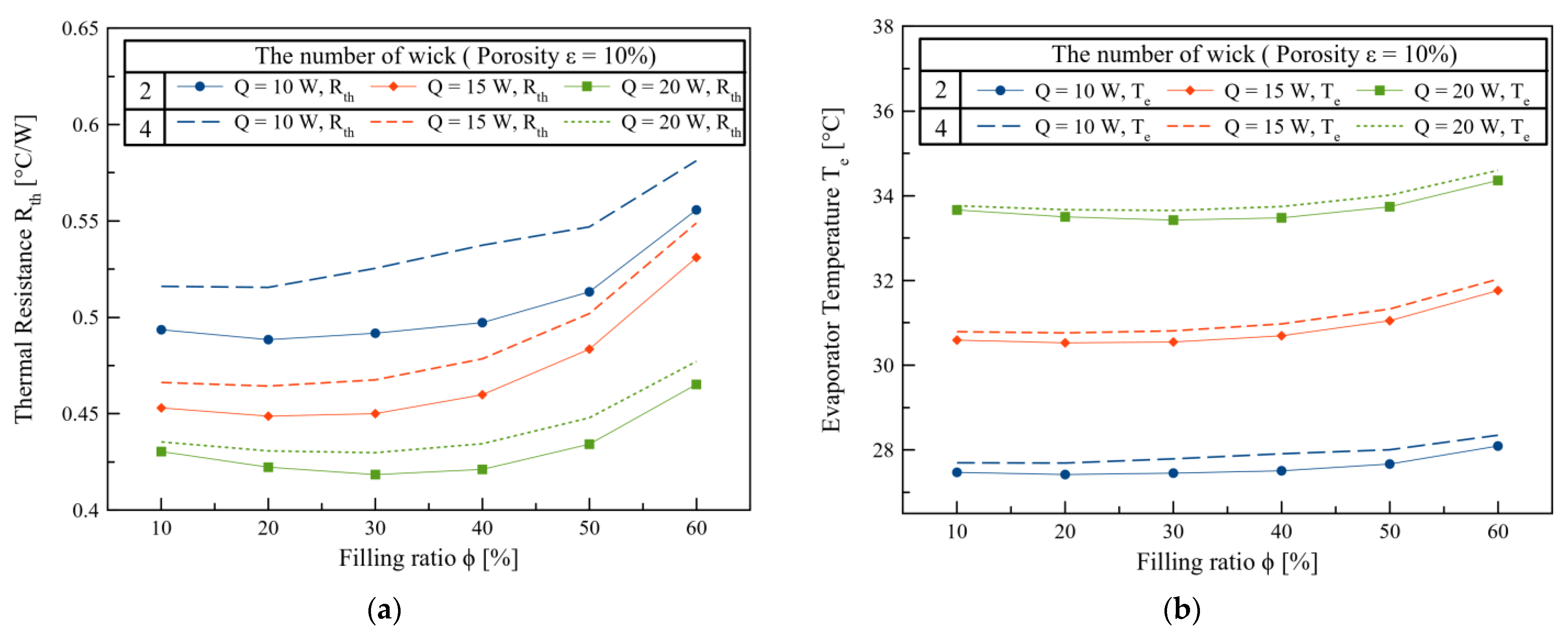
In Figure 4, when there are two wicks, they are attached only to both sides of the battery. In this configuration, some of the working fluid within the wick is vaporized by heat conducted from the battery, while the remainder vaporizes as it rises through the wick, driven by capillary forces. The vapor travels to a colder region near the cooling plate, where it condenses back into liquid form. Subsequently, the condensed liquid flows down along the heat pipe housing wall and returns to the working fluid reservoir, allowing for a continuous cycle of heat transfer through phase change. In contrast, Figure 16 shows a structure in which two wicks are attached to both sides of the battery, similar to the configuration in Figure 4, but with the addition of wicks affixed to both walls of the heat pipe housing.
Figure 16 illustrates two configurations involving wick placement in the heat pipe housing. The results of these configurations, presented in Figure 17, compare thermal resistance and evaporation temperature while considering filling ratio, heat supply, and the number of wicks, all at a porosity of 10%. Remarkably, when two wicks are employed, thermal resistance and evaporation temperature are lower compared to the case with four wicks. This observation can be attributed to gravity, which causes the natural downward flow of condensed liquid along the heat pipe housing wall when two wicks are attached to both sides of the battery. In contrast, with four wicks, the capillary force of the wick can impede the descent of some of the condensed liquid, hindering heat transfer and resulting in increased thermal resistance and evaporation temperature.
These results collectively offer valuable insights into the performance of our research model under various conditions, enabling informed decisions in the design and optimization of Battery Thermal Management Systems.
4. Conclusions
In this study, an extensive exploration of a novel Battery Thermal Management System (BTMS) was conducted using comprehensive 1-D modeling. The primary objectives focused on developing a system capable of preventing thermal runaway while optimizing heat dissipation across multiple design variables, including heat input, filling ratio, porosity, working fluid, heat pipe wick thickness, and the number of heat pipe wicks.
To validate the research model’s robustness, AMESim modeling was employed, comparing simulated outcomes with experimental data. This rigorous verification process confirmed a high degree of similarity between simulation and experimental results, affirming the model’s reliability. Subsequently, further 1-D modeling simulations using AMESim systematically explored various design variables within the context of the BTMS model.
The investigation was initiated by simulating evaporation temperatures with varying heat inputs. At 10 W, the evaporator temperature consistently ranged between approximately 27 °C and 28 °C. At 15 W, it stabilized between 30 °C and 31 °C, and at 20 W, it remained between 33 °C to 34 °C, aligning with the optimal lithium-ion battery operating temperature range of 20 °C to 40 °C. These results confirmed the system’s capability to maintain suitable temperatures across diverse heat inputs.
Crucially, optimal porosity and filling ratio values were identified to minimize thermal resistance. At 10 W, the lowest thermal resistance of 0.4549 °C/W was achieved with 60% porosity and a 30% filling ratio, while at 15 W, it was 0.415 °C/W with the same parameters. Finally, at 20 W, the lowest thermal resistance of 0.3848 °C/W occurred with 60% porosity and a 40% filling ratio, showcasing the BTMS’s performance under varied conditions.
The selection of the working fluid within the heat pipe emerged as a pivotal design variable, with NovecTM 649 exhibiting slightly reduced heat transfer efficiency compared to water due to its lower Merit number. However, NovecTM 649 effectively maintained the battery within the ideal temperature ranges for different heat inputs, offering additional insulation against thermal runaway and acting as a fire suppressant in critical situations.
The present study’s 1-D modeling investigations shed light on the complex interplay of design variables within the BTMS model, demonstrating its potential to prevent thermal runaway and optimize heat dissipation. Future research directions involve expanding investigations to the battery module level, promising weight reduction, miniaturization, and enhanced safety against thermal runaway phenomena.
Author Contributions
Conceptualization, S.-H.R., J.-S.L., I.-T.O., J.-S.H., S.-W.L. and S.-J.K.; methodology, I.-T.O. and J.-S.L.; software, S.-H.R., I.-T.O. and J.-S.L.; validation, I.-T.O. and J.-S.L.; formal analysis, I.-T.O. and J.-S.L.; investigation, I.-T.O., J.-S.H., J.-S.L. and S.-W.L.; resources, S.-H.R.; data curation, I.-T.O.; writing—original draft preparation, I.-T.O.; writing—review and editing, S.-H.R. and J.-S.L.; visualization, S.-H.R. and I.-T.O.; supervision, S.-H.R.; project administration, S.-H.R.; funding acquisition, S.-H.R. All authors have read and agreed to the published version of the manuscript.
Funding
This research was supported by NS Materials Co., Ltd. (Grant number: 2023092611).
Data Availability Statement
Data are contained within the article.
Acknowledgments
The authors are grateful to all colleagues and NS materials Inc. that contributed to this research and made it possible to publish its results.
Conflicts of Interest
The authors declare no conflict of interest.
Nomenclature
| A | |
| Hydraulic diameter, m | |
| f | Fiction coefficient |
| F | Correction factor |
| Gr | Grashof number, dimensionless |
| H | |
| h | Height, m |
| Lc | Characteristic length, m |
| l | Length, m |
| Total mass of the working fluid, kg | |
| Nu | Nusselt number, dimensionless |
| Pr | Prandtl number, dimensionless |
| Q | Heat transfer rate, W |
| Re | Reynolds number, dimensionless |
| t | Thickness, m |
| T | |
| V | |
| w | Liquid film thickness + Vapor core thickness, m |
| x | Quality |
| Greek | |
| Porosity, dimensionless | |
| Subscripts | |
| all | Total |
| c | Condenser, |
| cr | critical |
| cv | Convective |
| e | Evaporator |
| Effectiveness | |
| f | Fluid |
| l | Liquid |
| LO | Liquid only |
| NcB | Nucleate Boiling |
| plate | Cooling plate |
| TP | Two-phase flow |
| red | Reducing |
| v | Vapor |
| w | Wick |
| wall | Battery wall |
| surface | Surface |
| Surrounding air |
References
- Etacheri, V.; Marom, R.; Elazari, R.; Salitra, G.; Aurbach, D. Challenges in the Development of Advanced Li-Ion Batteries: A Review. Energy Environ. Sci. 2011, 4, 3243. [Google Scholar] [CrossRef]
- Xie, F.; Xu, J.; Liao, Q.; Zhang, Q.; Liu, B.; Shao, L.; Cai, J.; Shi, X.; Sun, Z.; Wong, C. Progress in niobium-based oxides as anode for fast-charging Li-ion batteries. Energy Rev. 2023, 2, 100027. [Google Scholar] [CrossRef]
- Shah, K.; Chalise, D.; Jain, A. Experimental and Theoretical Analysis of a Method to Predict Thermal Runaway in Li-Ion Cells. J. Power Sources 2016, 330, 167–174. [Google Scholar] [CrossRef]
- Wang, Q.; Ping, P.; Zhao, X.; Chu, G.; Sun, J.; Chen, C. Thermal Runaway Caused Fire and Explosion of Lithium Ion Battery. J. Power Sources 2012, 208, 210–224. [Google Scholar] [CrossRef]
- Lisbona, D.; Snee, T. A Review of Hazards Associated with Primary Lithium and Lithium-Ion Batteries. Process Saf. Environ. Prot. 2011, 89, 434–442. [Google Scholar] [CrossRef]
- Ling, Z.; Zhang, Z.; Shi, G.; Fang, X.; Wang, L.; Gao, X.; Fang, Y.; Xu, T.; Wang, S.; Liu, X. Review on Thermal Management Systems Using Phase Change Materials for Electronic Components, Li-Ion Batteries and Photovoltaic Modules. Renew. Sustain. Energy Rev. 2014, 31, 427–438. [Google Scholar] [CrossRef]
- Xie, Y.; He, X.; Hu, X.; Li, W.; Zhang, Y.; Liu, B.; Sun, Y. An Improved Resistance-Based Thermal Model for a Pouch Lithium-Ion Battery Considering Heat Generation of Posts. Appl. Therm. Eng. 2020, 164, 114455. [Google Scholar] [CrossRef]
- Li, Y.; Chen, M.; Bai, F.; Song, W.; Feng, Z. Thermal Equilibrium Characteristic of Large-Size Lithium-Ion Pouch Battery: Resting Time between Charge and Discharge. Energy Procedia 2019, 158, 2623–2630. [Google Scholar] [CrossRef]
- Pesaran, A. Battery Thermal Management in EVs and HEVs: Issues and Solutions. Battery Man 2001, 43, 34–49. [Google Scholar]
- Khan, M.R.; Swierczynski, M.J.; Kær, S.K. Towards an Ultimate Battery Thermal Management System: A Review. Batteries 2017, 3, 9. [Google Scholar] [CrossRef]
- Kim, J.; Oh, J.; Lee, H. Review on Battery Thermal Management System for Electric Vehicles. Appl. Therm. Eng. 2019, 149, 192–212. [Google Scholar] [CrossRef]
- Zhao, G.; Wang, X.; Negnevitsky, M.; Zhang, H. A Review of Air-Cooling Battery Thermal Management Systems for Electric and Hybrid Electric Vehicles. J. Power Sources 2021, 501, 230001. [Google Scholar] [CrossRef]
- Liu, Z.; Wang, Y.; Zhang, J.; Liu, Z. Shortcut Computation for the Thermal Management of a Large Air-Cooled Battery Pack. Appl. Therm. Eng. 2014, 66, 445–452. [Google Scholar] [CrossRef]
- Chen, K.; Wu, W.; Yuan, F.; Chen, L.; Wang, S. Cooling Efficiency Improvement of Air-Cooled Battery Thermal Management System through Designing the Flow Pattern. Energy 2019, 167, 781–790. [Google Scholar] [CrossRef]
- Kim, G.-H.; Pesaran, A. Battery Thermal Management Design Modeling. World Electr. Veh. J. 2007, 1, 126–133. [Google Scholar] [CrossRef]
- Xu, X.M.; He, R. Research on the Heat Dissipation Performance of Battery Pack Based on Forced Air Cooling. J. Power Sources 2013, 240, 33–41. [Google Scholar] [CrossRef]
- Sun, H.; Dixon, R. Development of Cooling Strategy for an Air Cooled Lithium-Ion Battery Pack. J. Power Sources 2014, 272, 404–414. [Google Scholar] [CrossRef]
- Na, X.; Kang, H.; Wang, T.; Wang, Y. Reverse Layered Air Flow for Li-Ion Battery Thermal Management. Appl. Therm. Eng. 2018, 143, 257–262. [Google Scholar] [CrossRef]
- Lu, Z.; Meng, X.Z.; Wei, L.C.; Hu, W.Y.; Zhang, L.Y.; Jin, L.W. Thermal Management of Densely-Packed EV Battery with Forced Air Cooling Strategies. Energy Procedia 2016, 88, 682–688. [Google Scholar] [CrossRef]
- Egab, K.; Oudah, S.K. Thermal Management Analysis of Li-Ion Battery-Based on Cooling System Using Dimples with Air Fins and Perforated Fins. Int. J. Therm. Sci. 2022, 171, 107200. [Google Scholar] [CrossRef]
- Shahjalal, M.; Shams, T.; Islam, M.E.; Alam, W.; Modak, M.; Hossain, S.B.; Ramadesigan, V.; Ahmed, M.R.; Ahmed, H.; Iqbal, A. A Review of Thermal Management for Li-Ion Batteries: Prospects, Challenges, and Issues. J. Energy Storage 2021, 39, 102518. [Google Scholar] [CrossRef]
- An, Z.; Shah, K.; Jia, L.; Ma, Y. A Parametric Study for Optimization of Minichannel Based Battery Thermal Management System. Appl. Therm. Eng. 2019, 154, 593–601. [Google Scholar] [CrossRef]
- Wu, W.; Wang, S.; Wu, W.; Chen, K.; Hong, S.; Lai, Y. A Critical Review of Battery Thermal Performance and Liquid Based Battery Thermal Management. Energy Convers. Manag. 2019, 182, 262–281. [Google Scholar] [CrossRef]
- Lu, M.; Zhang, X.; Ji, J.; Xu, X.; Zhang, Y. Research Progress on Power Battery Cooling Technology for Electric Vehicles. J. Energy Storage 2020, 27, 101155. [Google Scholar] [CrossRef]
- Saw, L.H.; Tay, A.A.O.; Zhang, L.W. Thermal Management of Lithium-Ion Battery Pack with Liquid Cooling. In Proceedings of the 2015 31st Thermal Measurement, Modeling & Management Symposium (SEMI-THERM), San Jose, CA, USA, 15–19 March 2015; IEEE: Piscataway, NJ, USA, 2015; pp. 298–302. [Google Scholar]
- Shang, Z.; Qi, H.; Liu, X.; Ouyang, C.; Wang, Y. Structural Optimization of Lithium-Ion Battery for Improving Thermal Performance Based on a Liquid Cooling System. Int. J. Heat Mass Transf. 2019, 130, 33–41. [Google Scholar] [CrossRef]
- Qian, Z.; Li, Y.; Rao, Z. Thermal Performance of Lithium-Ion Battery Thermal Management System by Using Mini-Channel Cooling. Energy Convers. Manag. 2016, 126, 622–631. [Google Scholar] [CrossRef]
- Sheng, L.; Su, L.; Zhang, H.; Li, K.; Fang, Y.; Ye, W.; Fang, Y. Numerical Investigation on a Lithium-Ion Battery Thermal Management Utilizing a Serpentine-Channel Liquid Cooling Plate Exchanger. Int. J. Heat Mass Transf. 2019, 141, 658–668. [Google Scholar] [CrossRef]
- Behi, H.; Behi, M.; Karimi, D.; Jaguemont, J.; Ghanbarpour, M.; Behnia, M.; Berecibar, M.; Van Mierlo, J. Heat Pipe Air-Cooled Thermal Management System for Lithium-Ion Batteries: High Power Applications. Appl. Therm. Eng. 2021, 183, 116240. [Google Scholar] [CrossRef]
- Al Hallaj, S.; Selman, J.R. A Novel Thermal Management System for Electric Vehicle Batteries Using Phase-Change Material. J. Electrochem. Soc. 2000, 147, 3231. [Google Scholar] [CrossRef]
- Huang, Y.-H.; Cheng, W.-L.; Zhao, R. Thermal Management of Li-Ion Battery Pack with the Application of Flexible Form-Stable Composite Phase Change Materials. Energy Convers. Manag. 2019, 182, 9–20. [Google Scholar] [CrossRef]
- Verma, A.; Shashidhara, S.; Rakshit, D. A Comparative Study on Battery Thermal Management Using Phase Change Material (PCM). Therm. Sci. Eng. Prog. 2019, 11, 74–83. [Google Scholar] [CrossRef]
- Deng, Y.; Feng, C.; Jiaqiang, E.; Zhu, H.; Chen, J.; Wen, M.; Yin, H. Effects of Different Coolants and Cooling Strategies on the Cooling Performance of the Power Lithium Ion Battery System: A Review. Appl. Therm. Eng. 2018, 142, 10–29. [Google Scholar] [CrossRef]
- Lv, Y.; Yang, X.; Li, X.; Zhang, G.; Wang, Z.; Yang, C. Experimental Study on a Novel Battery Thermal Management Technology Based on Low Density Polyethylene-Enhanced Composite Phase Change Materials Coupled with Low Fins. Appl. Energy 2016, 178, 376–382. [Google Scholar] [CrossRef]
- Alipanah, M.; Li, X. Numerical Studies of Lithium-Ion Battery Thermal Management Systems Using Phase Change Materials and Metal Foams. Int. J. Heat Mass Transf. 2016, 102, 1159–1168. [Google Scholar] [CrossRef]
- Hussain, A.; Tso, C.Y.; Chao, C.Y. Experimental Investigation of a Passive Thermal Management System for High-Powered Lithium Ion Batteries Using Nickel Foam-Paraffin Composite. Energy 2016, 115, 209–218. [Google Scholar] [CrossRef]
- Hémery, C.-V.; Pra, F.; Robin, J.-F.; Marty, P. Experimental Performances of a Battery Thermal Management System Using a Phase Change Material. J. Power Sources 2014, 270, 349–358. [Google Scholar] [CrossRef]
- Fathabadi, H. High Thermal Performance Lithium-Ion Battery Pack Including Hybrid Active–Passive Thermal Management System for Using in Hybrid/Electric Vehicles. Energy 2014, 70, 529–538. [Google Scholar] [CrossRef]
- Zhang, X.; Li, Z.; Luo, L.; Fan, Y.; Du, Z. A Review on Thermal Management of Lithium-Ion Batteries for Electric Vehicles. Energy 2022, 238, 121652. [Google Scholar] [CrossRef]
- Siddique, A.R.M.; Mahmud, S.; Van Heyst, B. A Comprehensive Review on a Passive (Phase Change Materials) and an Active (Thermoelectric Cooler) Battery Thermal Management System and Their Limitations. J. Power Sources 2018, 401, 224–237. [Google Scholar] [CrossRef]
- Feng, L.; Zhou, S.; Li, Y.; Wang, Y.; Zhao, Q.; Luo, C.; Wang, G.; Yan, K. Experimental Investigation of Thermal and Strain Management for Lithium-Ion Battery Pack in Heat Pipe Cooling. J. Energy Storage 2018, 16, 84–92. [Google Scholar] [CrossRef]
- Smith, J.; Singh, R.; Hinterberger, M.; Mochizuki, M. Battery Thermal Management System for Electric Vehicle Using Heat Pipes. Int. J. Therm. Sci. 2018, 134, 517–529. [Google Scholar] [CrossRef]
- Greco, A.; Cao, D.; Jiang, X.; Yang, H. A Theoretical and Computational Study of Lithium-Ion Battery Thermal Management for Electric Vehicles Using Heat Pipes. J. Power Sources 2014, 257, 344–355. [Google Scholar] [CrossRef]
- Yuan, W.; Yan, Z.; Tan, Z.; Chen, W.; Tang, Y. Heat-Pipe-Based Thermal Management and Temperature Characteristics of Li-Ion Batteries. Can. J. Chem. Eng. 2016, 94, 1901–1908. [Google Scholar] [CrossRef]
- Roe, C.; Feng, X.; White, G.; Li, R.; Wang, H.; Rui, X.; Li, C.; Zhang, F.; Null, V.; Parkes, M. Immersion Cooling for Lithium-Ion Batteries—A Review. J. Power Sources 2022, 525, 231094. [Google Scholar] [CrossRef]
- Lander, L.; Kallitsis, E.; Hales, A.; Edge, J.S.; Korre, A.; Offer, G. Cost and Carbon Footprint Reduction of Electric Vehicle Lithium-Ion Batteries through Efficient Thermal Management. Appl. Energy 2021, 289, 116737. [Google Scholar] [CrossRef]
- Patil, M.S.; Seo, J.-H.; Lee, M.-Y. A Novel Dielectric Fluid Immersion Cooling Technology for Li-Ion Battery Thermal Management. Energy Convers. Manag. 2021, 229, 113715. [Google Scholar] [CrossRef]
- Nelson, P.; Dees, D.; Amine, K.; Henriksen, G. Modeling Thermal Management of Lithium-Ion PNGV Batteries. J. Power Sources 2002, 110, 349–356. [Google Scholar] [CrossRef]
- Patil, M.S.; Seo, J.H.; Bang, Y.M.; Kim, D.W.; Ekanayake, G.; Singh, G.; Kim, H.M.; Choi, Y.H.; Lee, M.Y. A Novel Design for Lithium Ion Battery Cooling Using Mineral Oil. In Proceedings of the 3rd International Mega-Conference on Green and Smart Technology (GST 2016), Jeju Island, Republic of Korea, 21–23 December 2016; pp. 21–23. [Google Scholar]
- Zhou, H.; Dai, C.; Liu, Y.; Fu, X.; Du, Y. Experimental investigation of battery thermal management and safety with heat pipe andimmersion phase change liquid. J. Power Sources 2020, 473, 228545. [Google Scholar] [CrossRef]
- Dubey, P.; Pulugundla, G.; Srouji, A.K. Direct comparison of immersion and cold-plate based cooling for automotive Li-ion battery modules. Energies 2021, 14, 1259. [Google Scholar] [CrossRef]
- Li, Y.; Zhou, Z.; Hu, L.; Bai, M.; Gao, L.; Li, Y.; Liu, X.; Li, Y.; Song, Y. Experimental studies of liquid immersion cooling for 18650 lithium-ion battery under different discharging conditions. Case Stud. Therm. Eng. 2022, 34, 102034. [Google Scholar] [CrossRef]
- Jithin, K.V.; Rajesh, P.K. Numerical analysis of single-phase liquid immersion cooling for lithium-ion battery thermal management using different dielectric fluids. Int. J. Heat Mass Transf. 2022, 188, 122608. [Google Scholar] [CrossRef]
- Giammichele, L.; D’Alessandro, V.; Falone, M.; Ricci, R. Experimental study of a direct immersion liquid cooling of a Li-ion battery for electric vehicles applications. Int. J. Heat Technol. 2022, 40, 1–8. [Google Scholar] [CrossRef]
- Williams, N.P.; O’Shaughnessy, S.M. Immersion Cooling of Lithium-ion Batteries for Electric Vehicles. In Proceedings of the 2022 28th International Workshop on Thermal Investigations of ICs and Systems (THERMINIC), Dublin, Ireland, 28–30 September 2022; pp. 1–4. [Google Scholar]
- Han, J.W.; Garud, K.S.; Hwang, S.G.; Lee, M.Y. Experimental Study on Dielectric Fluid Immersion Cooling for Thermal Management of Lithium-Ion Battery. Symmetry 2022, 14, 2126. [Google Scholar] [CrossRef]
- Luo, M.; Cao, J.; Liu, N.; Zhang, Z.; Fang, X. Experimental and Simulative Investigations on a Water Immersion Cooling System for Cylindrical Battery Cells. Front. Energy Res. 2022, 10, 803882. [Google Scholar] [CrossRef]
- Wang, Y.F.; Li, B.; Hu, Y.; Mao, Z.; Song, B.; Tian, W.; Sunden, B. Experimental study on immersion phase change cooling of lithium-ion batteries based on R1233ZD (E)/ethanol mixed refrigerant. Appl. Therm. Eng. 2023, 220, 119649. [Google Scholar] [CrossRef]
- Satyanarayana, G.; Sudhakar, D.R.; Goud, V.M.; Ramesh, J.; Pathanjali, G.A. Experimental investigation and comparative analysis of immersion cooling of lithium-ion batteries using mineral and therminol oil. Appl. Therm. Eng. 2023, 225, 120187. [Google Scholar] [CrossRef]
- Li, Y.; Bai, M.; Zhou, Z.; Wu, W.-T.; Lv, J.; Gao, L.; Huang, H.; Li, Y.; Li, Y.; Song, Y. Experimental investigations of liquid immersion cooling for 18650 lithium-ion battery pack under fast charging conditions. Appl. Therm. Eng. 2023, 227, 120287. [Google Scholar] [CrossRef]
- Wang, Z.; Zhao, R.; Wang, S.; Huang, D. Heat transfer characteristics and influencing factors of immersion coupled direct cooling for battery thermal management. J. Energy Storage 2023, 62, 106821. [Google Scholar] [CrossRef]
- Celen, A. Experimental Investigation on Single-Phase Immersion Cooling of a Lithium-Ion Pouch-Type Battery under Various Operating Conditions. Appl. Sci. 2023, 13, 2775. [Google Scholar] [CrossRef]
- Choi, H.; Lee, H.; Kim, J.; Lee, H. Hybrid single-phase immersion cooling structure for battery thermal management under fast-charging conditions. Energy Convers. Manag. 2023, 287, 117053. [Google Scholar] [CrossRef]
- Shah, J.M.; Eiland, R.; Siddarth, A.; Agonafer, D. Effects of Mineral Oil Immersion Cooling on IT Equipment Reliability and Reliability Enhancements to Data Center Operations. In Proceedings of the 2016 15th IEEE Intersociety Conference on Thermal and Thermomechanical Phenomena in Electronic Systems (ITherm), Las Vegas, NV, USA, 31 May–3 June 2016; IEEE: Piscataway, NJ, USA, 2016; pp. 316–325. [Google Scholar]
- Vincent, M.; Ghaffari, O.; Nabavi Larimi, Y.; Grenier, F.; Jasmin, S.; Fréchette, L.; Sylvestre, J. Experimental Investigation of the Thermal Resistance of Advanced Novel Two-Phase Thermosyphon Heatsinks. Available at SSRN 4457244. Available online: https://papers.ssrn.com/sol3/papers.cfm?abstract_id=4457244 (accessed on 25 June 2023).
- 3M NovecTM 649 Engineered Fluid Datasheet. Available online: http://www.lookpolymers.com/polymer_3M-Novec-649-Engineered-Fluid.php (accessed on 8 August 2023).
- Table 3-Thermal Properties of the Manufactured Nonwoven. Available online: https://www.researchgate.net/figure/Thermal-properties-of-the-manufactured-nonwoven_tbl3_322982943 (accessed on 27 June 2023).
- Kaviany, M. Principles of Heat Transfer in Porous Media; Springer Science & Business Media: Berlin, Germany, 2012. [Google Scholar]
- SIEMENS. Integration Algorithms and Library User Guides Used in Simcenter Amesim; SIEMENS: Munich, Germany, 2020; Available online: https://plm.sw.siemens.com/en-US/simcenter/systems-simulation/amesim/ (accessed on 26 June 2023).
- Patil, K.; Molla, S.K.; Schulze, T. Hybrid Vehicle Model Development Using ASM-AMESim-Simscape Co-Simulation for Real-Time HIL Applications. In Proceedings of the SAE 2012 World Congress & Exhibition, Detroit, MI, USA, 24–26 April 2012. [Google Scholar]
- Zhao, Q.; Duan, J.J.; Wang, C. Modeling and Simulation of Vehicle Hydraulic ABS Based on AMEsim. Adv. Mater. Res. 2012, 590, 441–445. [Google Scholar] [CrossRef]
- El-Nasr, A.A.; El-Haggar, S.M. Effective Thermal Conductivity of Heat Pipes. Heat Mass Transf. 1996, 32, 97–101. [Google Scholar] [CrossRef]
- Kapekov, A. Development of an Innovative Cooling Concept for Turbofan Engines. 2018. Available online: http://kth.diva-portal.org/smash/record.jsf?pid=diva2:1295797 (accessed on 3 March 2023).
- Peterson, G.P. An Introduction to Heat Pipes; John Wiley& Sons. Inc.: New York, NY, USA, 1994. [Google Scholar]
- Chan, C.W.; Siqueiros, E.; Ling-Chin, J.; Royapoor, M.; Roskilly, A.P. Heat Utilisation Technologies: A Critical Review of Heat Pipes. Renew. Sustain. Energy Rev. 2015, 50, 615–627. [Google Scholar] [CrossRef]
- Wallin, P. Heat Pipe, Selection of Working Fluid. Heat and Mass Trasfer Project Report. 2012. pp. 1–7. Available online: https://www.ht.energy.lth.se/fileadmin/ht/Kurser/MVK160/2012/Per_Wallin.pdf (accessed on 25 March 2023).
- Anand, A.R.; Vedamurthy, A.J.; Chikkala, S.R.; Kumar, S.; Kumar, D.; Gupta, P.P. Analytical and Experimental Investigations on Axially Grooved Aluminum-Ethane Heat Pipe. Heat Transf. Eng. 2008, 29, 410–416. [Google Scholar] [CrossRef]
- Reay, D.; McGlen, R.; Kew, P. Heat Pipes: Theory, Design and Applications; Butterworth-Heinemann: Oxford, UK, 2013. [Google Scholar]
- Gou, J.; Liu, W. Feasibility Study on a Novel 3D Vapor Chamber Used for Li-Ion Battery Thermal Management System of Electric Vehicle. Appl. Therm. Eng. 2019, 152, 362–369. [Google Scholar] [CrossRef]
- Li, H.; Liu, Z.; Chen, B.; Liu, W.; Li, C.; Yang, J. Development of Biporous Wicks for Flat-Plate Loop Heat Pipe. Exp. Therm. Fluid Sci. 2012, 37, 91–97. [Google Scholar] [CrossRef]
- Li, J.; Lu, N.; Sun, Y. Research Progress and Prospect of Heat Pipe Capillary Wicks. Front. Heat Mass Transf. (FHMT) 2022, 18. [Google Scholar] [CrossRef]
- Brautsch, A.; Kew, P.A. Examination and Visualisation of Heat Transfer Processes during Evaporation in Capillary Porous Structures. Appl. Therm. Eng. 2002, 22, 815–824. [Google Scholar] [CrossRef]
- Li, C.; Peterson, G.P.; Wang, Y. Evaporation/Boiling in Thin Capillary Wicks (l)—Wick Thickness Effects. 2006. Available online: https://www.researchgate.net/publication/245362585_EvaporationBoiling_in_Thin_Capillary_Wicks_l-Wick_Thickness_Effects (accessed on 5 March 2023).
- Chang, F.L.; Hung, Y.M. The Coupled Effects of Working Fluid and Solid Wall on Thermal Performance of Micro Heat Pipes. Int. J. Heat Mass Transf. 2014, 73, 76–87. [Google Scholar] [CrossRef]
- Henderson-Sellers, B. A New Formula for Latent Heat of Vaporization of Water as a Function of Temperature. Q. J. R. Meteorol. Soc. 1984, 110, 1186–1190. [Google Scholar] [CrossRef]
- Kestin, J.; Sokolov, M.; Wakeham, W.A. Viscosity of Liquid Water in the Range −8 °C to 150 °C. J. Phys. Chem. Ref. Data 1978, 7, 941–948. [Google Scholar] [CrossRef]
- Vargaftik, N.B.; Volkov, B.N.; Voljak, L.D. International Tables of the Surface Tension of Water. J. Phys. Chem. Ref. Data 1983, 12, 817–820. [Google Scholar] [CrossRef]
- Larrañaga, A.; Gómez, M.A.; Patiño, D.; Porteiro, J. Experimental Study on the Stability and Transient Behavior of a Closed-Loop Two-Phase Thermosyphon (CLTPT) Charged with NOVEC 649. Energies 2021, 14, 7920. Available online: https://www.mdpi.com/1996-1073/14/23/7920 (accessed on 1 August 2023). [CrossRef]
- Chupka, G.M.; Christensen, E.; Fouts, L.; Alleman, T.L.; Ratcliff, M.A.; McCormick, R.L. Heat of Vaporization Measurements for Ethanol Blends Up To 50 Volume Percent in Several Hydrocarbon Blendstocks and Implications for Knock in SI Engines. SAE Int. J. Fuels Lubr. 2015, 8, 251–263. [Google Scholar] [CrossRef]
- Gonçalves, F.A.M.M.; Trindade, A.R.; Costa, C.S.M.F.; Bernardo, J.C.S.; Johnson, I.; Fonseca, I.M.A.; Ferreira, A.G.M. PVT, Viscosity, and Surface Tension of Ethanol: New Measurements and Literature Data Evaluation. J. Chem. Thermodyn. 2010, 42, 1039–1049. [Google Scholar] [CrossRef]
- Dunn, P.D.; Reay, D.A. The Heat Pipe. Phys. Technol. 1973, 4, 187–201. [Google Scholar] [CrossRef]
Figure 1.
Principle of heat pipe.
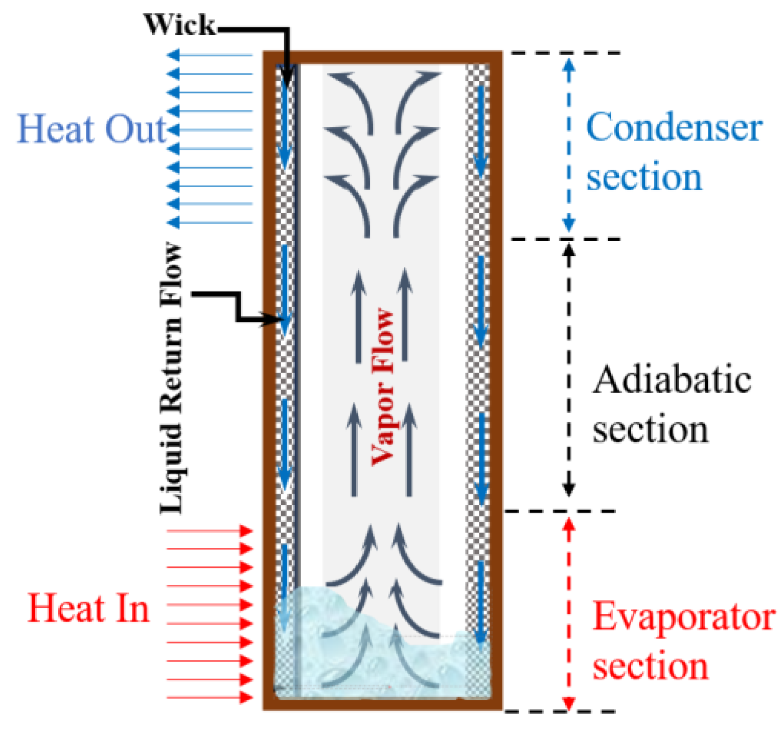
Figure 2.
Schematics of immersion cooling system using a heat pipe.

Figure 3.
Conceptional view of battery embedded heat pipe Immersion cooling system.
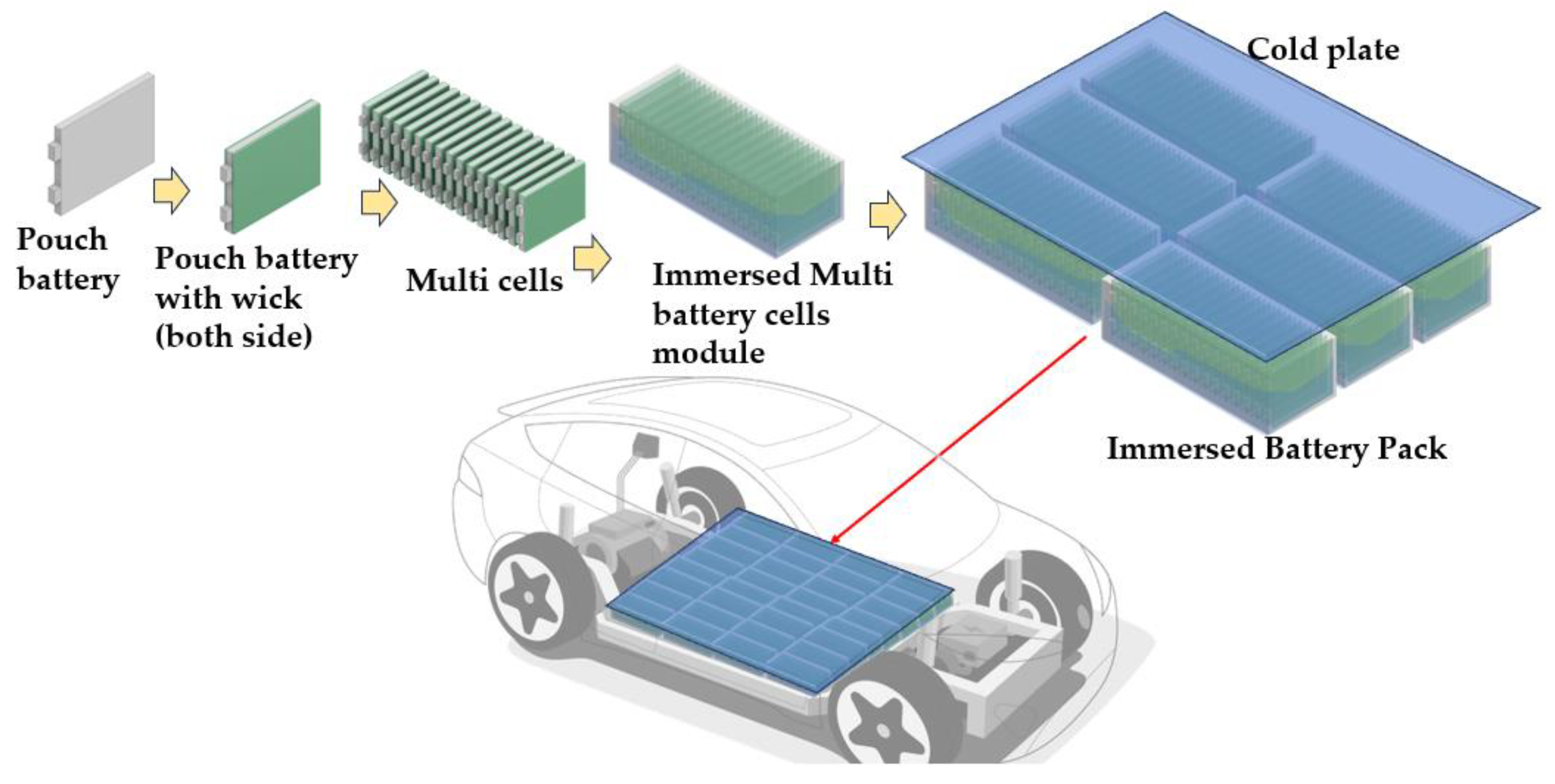
Figure 4.
Principle of heat pipe embedded immersion cooling system.
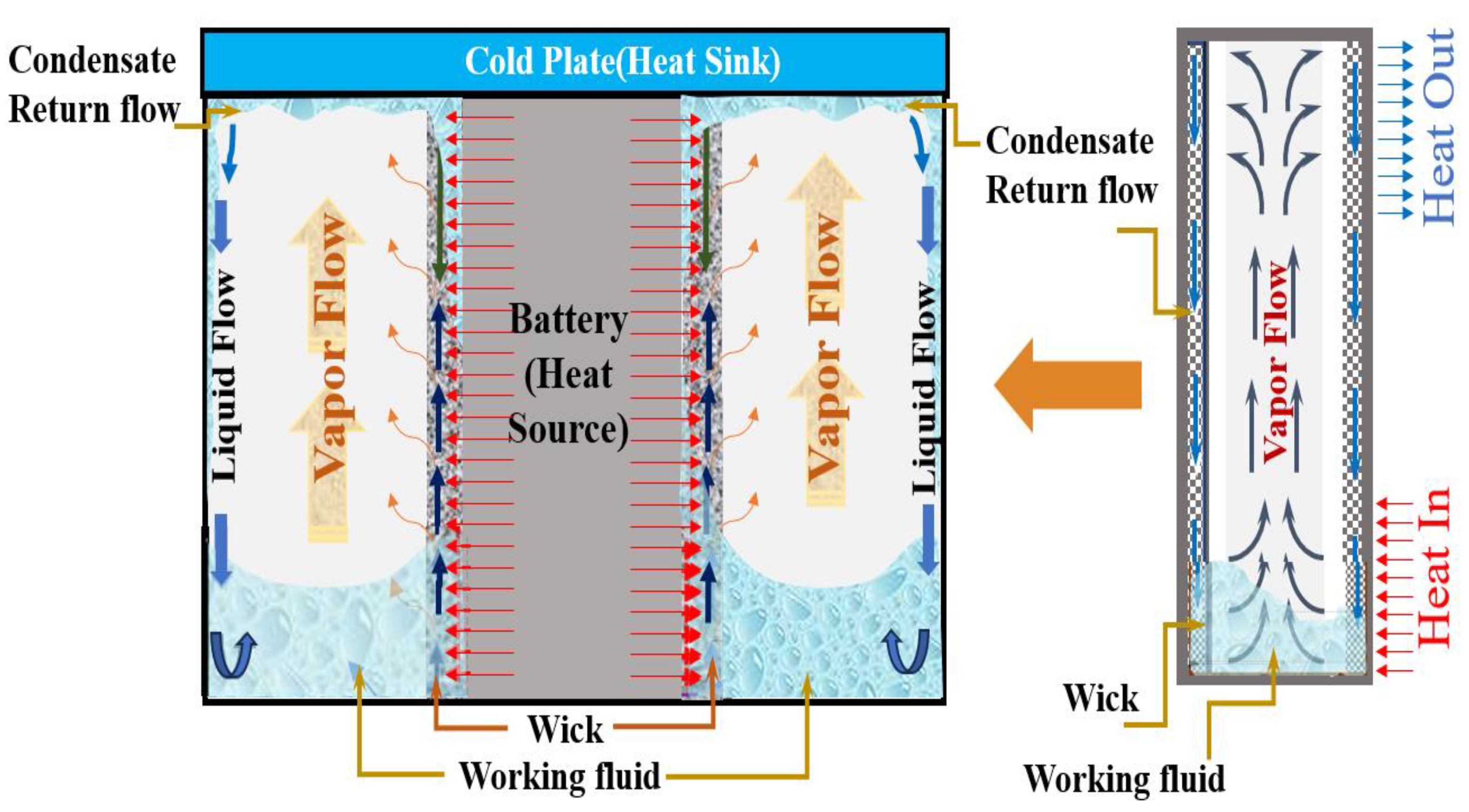
Figure 5.
One-dimensional AMESim modeling of the BTMS.

Figure 6.
Thermal resistance network of immersion cooling system using heat pipe.
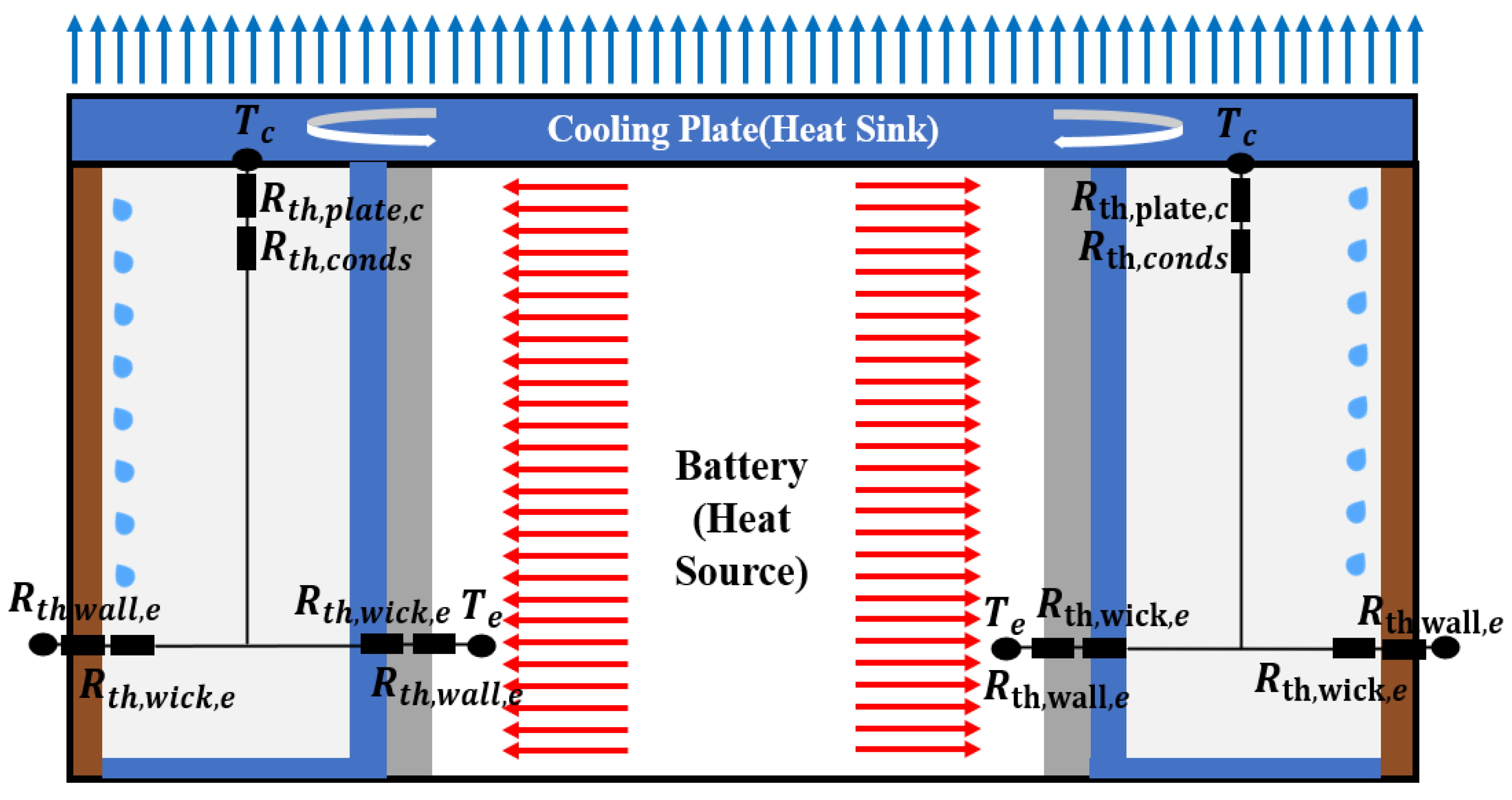
Figure 7.
Conduction involving two materials and contact thermal resistance.
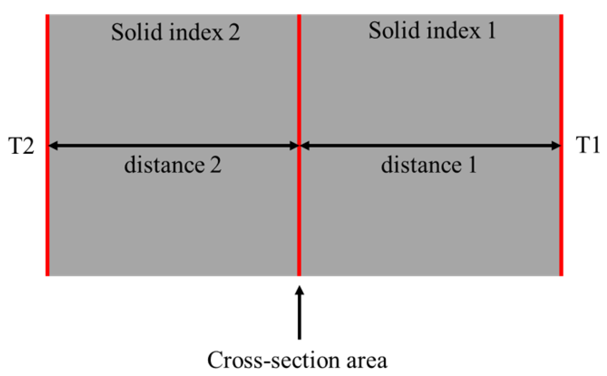
Figure 8.
One-dimensional AMESim modeling of the validation model.
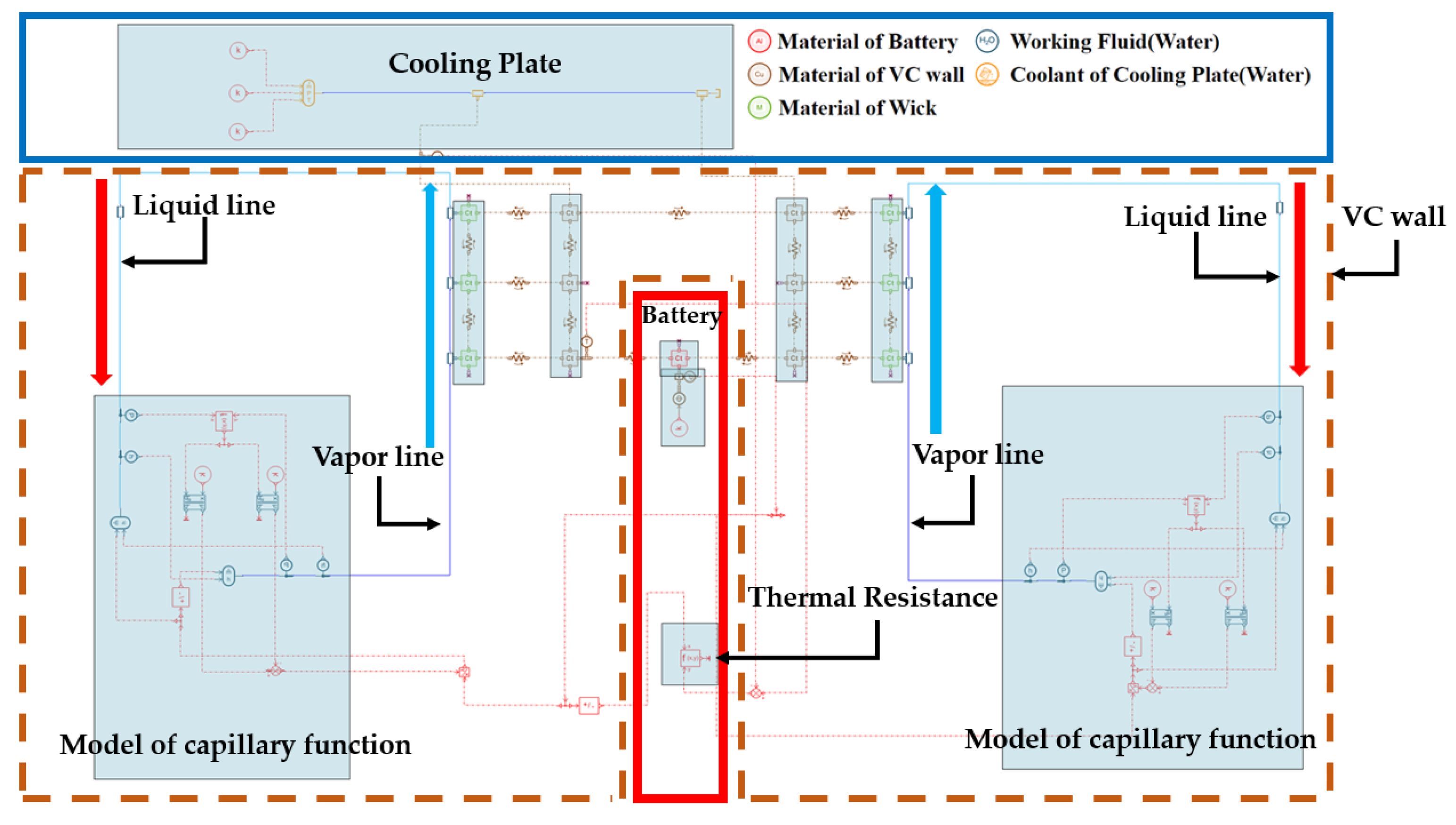
Figure 9.
Experimental and simulation results of the validation model [66].
Figure 9.
Experimental and simulation results of the validation model [66].
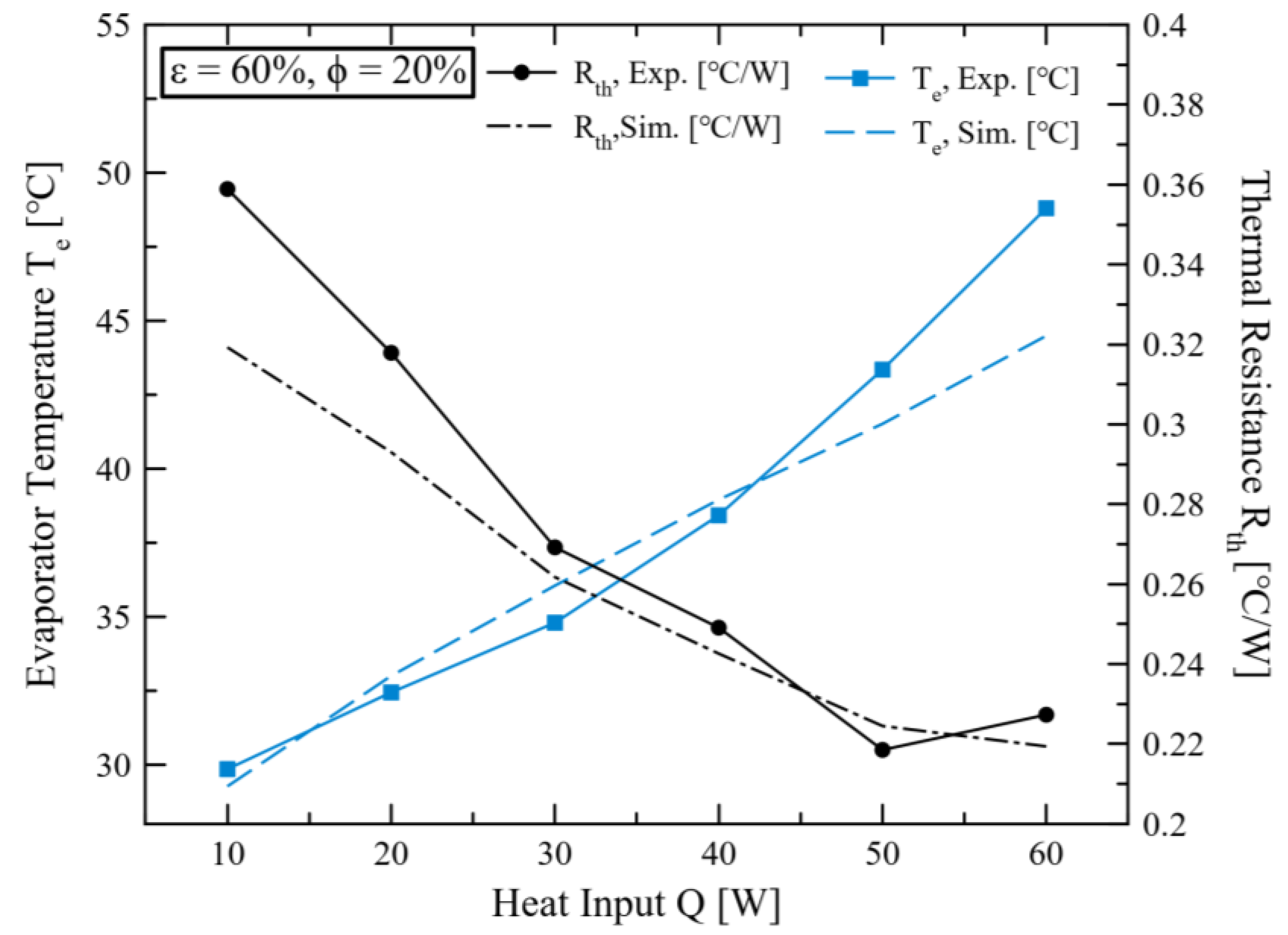
Figure 10.
(a) Thermal resistance according to the filling ratio ( = 60%). (b) Evaporator temperature according to the filling ratio ( = 60%).
Figure 10.
(a) Thermal resistance according to the filling ratio ( = 60%). (b) Evaporator temperature according to the filling ratio ( = 60%).
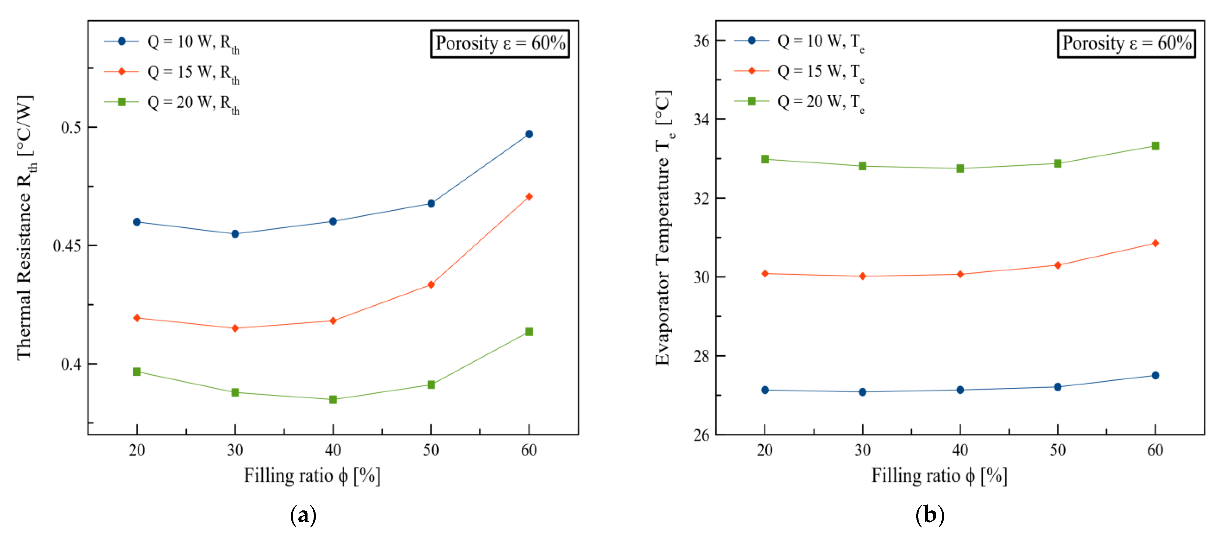
Figure 11.
(a) Thermal resistance according to porosity (). (b) Thermal resistance according to porosity ().
Figure 11.
(a) Thermal resistance according to porosity (). (b) Thermal resistance according to porosity ().
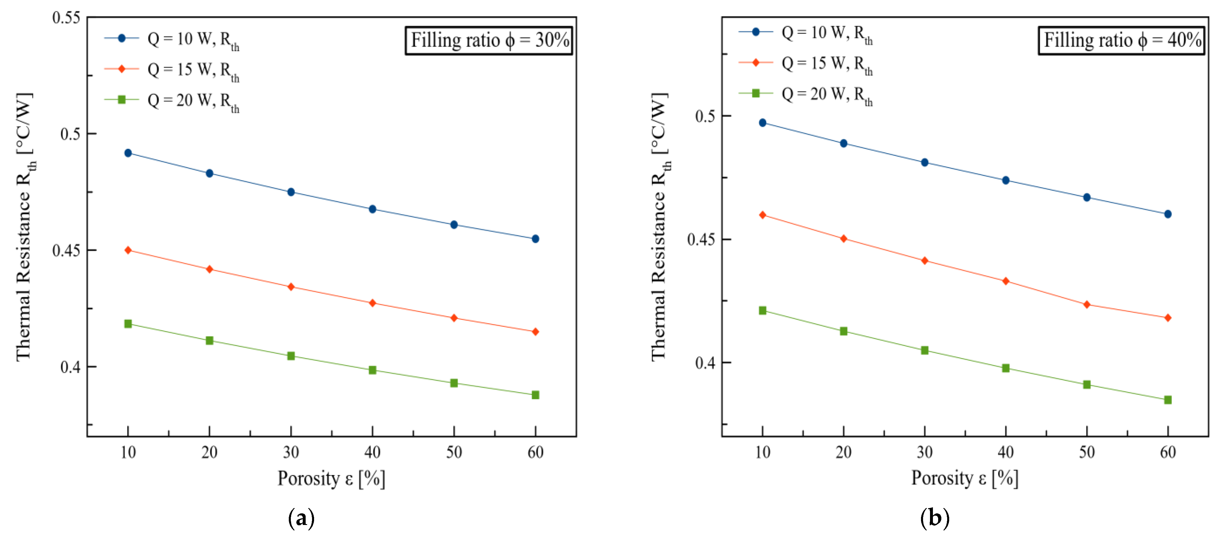
Figure 12.
Temperature (evaporator, condenser) according to filling ratio.
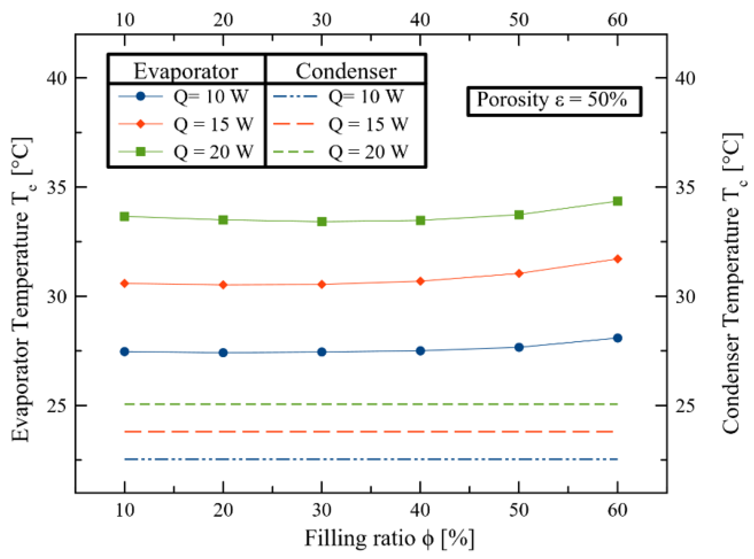
Figure 13.
Thermal resistance and evaporator temperature according to wick thickness.
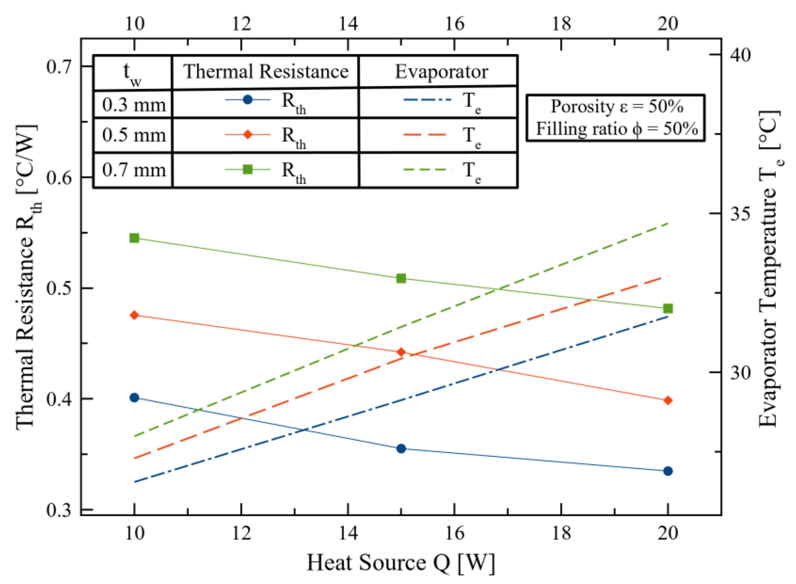
Figure 14.
Merit number of working fluid at various temperature.

Figure 15.
(a) Thermal resistance according to working fluid. (b) Evaporator temperature according to working fluid.
Figure 15.
(a) Thermal resistance according to working fluid. (b) Evaporator temperature according to working fluid.

Figure 16.
Principle of immersion cooling system using heat pipe, model with wicks on all sides.

Figure 17.
(a) Thermal resistance according to wick layers (b) evaporator temperature according to wick layers.
Figure 17.
(a) Thermal resistance according to wick layers (b) evaporator temperature according to wick layers.

Table 1.
Properties of wick and working fluid.
| Thermal Conductivity, K | Specific Heat | ||
|---|---|---|---|
| Non-woven | 0.038 | 400 | 1200 |
| NovecTM 649 | 0.059 | 1600 | 1103 |
Table 2.
Initial condition and boundary condition of BTMS.
| Category | Conditions |
|---|---|
| Material of battery | Aluminum |
| Material of wick | Non-woven |
| Working fluid | NovecTM 649, Water, Ethanol, Methanol |
| Coolant of cooling plate | Water |
| Initial temperature of battery (°C) | 35 |
| Temperature of cooling plate coolant (°C) | 20 |
| Mass flow rate of coolant (L/min) | 2.4 |
| Thickness of wick (mm) | 0.3, 0.5, 0.7 |
| Porosity (%) | 10~60 |
| Filling ratio (%) | 10~60 |
| Heat input (W) | 10, 15, 20 |
Table 3.
Main AMESim library components used in the BTMS model [69].
Table 3.
Main AMESim library components used in the BTMS model [69].
| Library Component | Component Name | Description |
|---|---|---|
 | Thermal capacity | It computes the temperature dynamics of a solid mass with respect to incoming heat flux. |
 | Conductive exchange | Generic conduction. |
 | Temperature sensor | It is a tool to measure the temperature of the evaporation part and the condensation part of this research model. |
 | Conversion of signal to a heat flow | Conversion of signal to a heat flow. |
 | Power/Energy/Activity sensor | This sensor is used to compute the power or energy at ports of one system’s component. |
 | Thermal plug | It can stop the heat flow rate at a port. |
 | Thermal properties | Thermal properties. |
 | Thermodynamic state transformer | It can choose between nine predefined choices to define the thermodynamic state at input and at output. |
 | Fluid property sensor | Generic sensor with additional thermodynamic state variable. |
 | Two-phase flow pipe volume | Pipe with heat exchange with 2 thermal ports (R-C), related to various two-phase flow models. |
 | Modulated source | A modulated source of mass flow rate and enthalpy flow rate. |
 | Fluid property(two-phase) | Fluid property (two-phase). |
 | Modulated source | A modulated source of mass flow rate, temperature rate, and pressure rate. |
 | Thermal-hydraulic pipe volume | Pipe with heat exchange with thermal port (C-R), related to various thermal-hydraulic models. |
 | Thermal-hydraulic fluid property | Thermal-hydraulic fluid property. |
 | Constant signal | outputs a signal with a constant specified value. |
 | Mathematical function | It applies a user supplied function to two signals input at ports X and Y, and the result is the output on another port. |
 | Reverse the sign of input | A signal conversion submodel that reverses the sign of the input signal. |
 | Division function | Division function. |
Table 4.
Initial conditions of experimental work [79].
Table 4.
Initial conditions of experimental work [79].
| Category | Condition |
|---|---|
| Material of battery | Aluminum |
| Material of wick | No. 200 Sintered Copper |
| Working fluid | Water |
| Coolant of cooling plate | Water |
| Initial temperature of battery (°C) | 35 |
| Temperature of cooling plate coolant (°C) | 25 |
| Mass flow rate of coolant (L/min) | 3 |
| Thickness of wick (mm) | 0.5 |
| Porosity (%) | 60 |
| Filling ratio (%) | 10, 20 |
| Heat input (W) | 10~60 |
Disclaimer/Publisher’s Note: The statements, opinions and data contained in all publications are solely those of the individual author(s) and contributor(s) and not of MDPI and/or the editor(s). MDPI and/or the editor(s) disclaim responsibility for any injury to people or property resulting from any ideas, methods, instructions or products referred to in the content. |
© 2023 by the authors. Licensee MDPI, Basel, Switzerland. This article is an open access article distributed under the terms and conditions of the Creative Commons Attribution (CC BY) license (https://creativecommons.org/licenses/by/4.0/).
Share and Cite
MDPI and ACS Style
Oh, I.-T.; Lee, J.-S.; Han, J.-S.; Lee, S.-W.; Kim, S.-J.; Rhi, S.-H. Li-Ion Battery Immersed Heat Pipe Cooling Technology for Electric Vehicles. Electronics 2023, 12, 4931. https://doi.org/10.3390/electronics12244931
AMA Style
Oh I-T, Lee J-S, Han J-S, Lee S-W, Kim S-J, Rhi S-H. Li-Ion Battery Immersed Heat Pipe Cooling Technology for Electric Vehicles. Electronics. 2023; 12(24):4931. https://doi.org/10.3390/electronics12244931
Chicago/Turabian StyleOh, In-Taek, Ji-Su Lee, Jin-Se Han, Seong-Woo Lee, Su-Jong Kim, and Seok-Ho Rhi. 2023. "Li-Ion Battery Immersed Heat Pipe Cooling Technology for Electric Vehicles" Electronics 12, no. 24: 4931. https://doi.org/10.3390/electronics12244931
Note that from the first issue of 2016, this journal uses article numbers instead of page numbers. See further details here.