

Noise Reduction Method for the Vibration Signal of Reactor CRDM Based on CEEMDAACN-SK
by

Zhilong Liu
1,2,
Tongxi Li
2,
Zhifeng Zhu
2,
Minggang Li
2,
Changhua Nie
2 and
Zhangchun Tang
1,* 1
School of Mechanical and Electrical Engineering, University of Electronic Science and Technology of China, Chengdu 611731, China
2
Institute of Reactor Power Engineering, Nuclear Power Institute of China, Chengdu 610000, China
*
Author to whom correspondence should be addressed.
Electronics 2023, 12(22), 4681; https://doi.org/10.3390/electronics12224681
Submission received: 16 August 2023
/
Revised: 2 October 2023
/
Accepted: 5 October 2023
/
Published: 17 November 2023
(This article belongs to the Special Issue New Insight in Power Electronics of Topology, Control, and Application System)
Abstract
:The reactor control rod drive mechanism (CRDM) controls the startup, shutdown and power of the reactor; it is one of the key pieces of equipment to ensure the normal operation of the reactor. CRDM is complex, mainly composed of stator, rotor, bearing, roller, etc. The characteristic analysis of the vibration monitoring signal is one of the important methods of the CRDM state evaluation. In view of the characteristics of large noise interference and the difficulty in analyzing the vibration monitoring signal of CRDM, this paper proposes a noise reduction method for the vibration signal of CRDM based on complete ensemble empirical mode decomposition with adaptive amplitude correction noise and spectral kurtosis (CEEMDAACN-SK), which can deeply reduce the vibration signal of CRDM. Firstly, the proposed CEEMDAACN algorithm is used to decompose the vibration signal of CRDM to obtain multiple intrinsic mode functions (IMF). Then, the spectral kurtosis of each IMF component is analyzed to obtain the spectral kurtosis map of each IMF component, which is compared with the spectral kurtosis map of the original signal. Finally, the denoising reconstruction of the signal is carried out to obtain the final denoising signal. Through experimental analysis, the performance of the proposed CEEMDAACN-SK denoising algorithm is better than the complete ensemble empirical mode decomposition with adaptive noise and spectral kurtosis (CEEMDAN-SK) algorithm in terms of results. The method proposed in this paper can be applied not only to the vibration signal noise reduction of CRDM, but also to other equipment and fields, such as nuclear power main circulation pump and the chemical industry.
1. Introduction
At present, the research on the CRDM of a nuclear reactor mainly focuses on the structural reliability optimization and design of a CRDM, reliability and function analysis under accident environment, fault analysis and detection, rod drop reliability and performance analysis. The research involves the reliability design, performance analysis and reliability maintenance of a CRDM. Through the continuous research of the above contents, the researchers aim to ensure the reliable operation of a CRDM, so as to ensure the safe operation of nuclear reactors.
Refs. [1,2,3,4,5,6] introduced the research contents related to reliability optimization and the design of the CRDM of a nuclear reactor in recent years. The Korean Institute of atomic energy has developed and designed the prototype of the bottom mounted CRDM for the Kijang research reactor (KJRR) and compared the similarities and differences of some research reactors’ CRDM [1]. A passive core cooling system is proposed [2]. The passive core cooling system is composed of a hydraulic CRDM and a hybrid control rod assembly to delay the fuel melting time and improve the safety of the nuclear power plant during the power failure accident of the nuclear power plant, which is finally verified by experiments. In order to ensure the service life of a CRDM working in a high temperature, high pressure and nuclear radiation environment, the problem of uneven chromium plating thickness caused by poor throwing force of chromium plating solution was studied [3]. The research results can provide reference for the specification of chromium plating thickness of a CRDM. Tsinghua University studied the control rod hydraulic drive mechanism (CRHDM), obtained the theoretical model of the hydraulic cylinder operation process of the drive mechanism and verified it through experiments, further analyzed the parameters of the hydraulic cylinder, and optimized the cylinder and drive mechanism [4]. In order to improve the reliability of a CRDM, the literature [5] proposes a reliability trade-off method aiming at total cost reliability. A goal-oriented model is established, and the total cost reliability composed of production cost and operation and maintenance cost is taken as the objective function of the model. Then, based on the method and genetic algorithm, the reliability trade-off optimization allocation result of a CRDM is obtained. Researchers from dahol State University have reduced the overall complexity and failure probability through appropriate material selection and structural improvements of the design to improve the overall reliability of the reactor and the reliability of the long-term operation of the reactor [6], aiming at the aging and failure of the CRDM of an agn-201m reactor. Refs. [7,8,9,10] introduce the research contents related to the reliability and function analysis of a CRDM in a nuclear reactor under accident environment in recent years. The integrated intrinsically safe light water reactor (i2s-lwr) is a new type of pressurized water reactor (PWR), which was developed under the leadership of the Georgia Institute of technology. The overall design of the primary coolant and control rod drive system of this reactor is introduced [7]. This design eliminates the possibility of a large amount of fracture loss of the coolant and of a control rod ejection accident and improves the reliability of the reactor and drive mechanism. In a medium-sized oxide fuel fast breeder reactor, the possibility of improving core safety under unprotected loss of current (ULOF) and unprotected transient over power (UTOP) accidents is discussed and studied by using the control and safety rod drive mechanism (CSRDM) [8]. Under the premise that the reliability analysis considering the common CRDM fault tree cannot be found in any public references, the purpose of ref. [9] is to study the RCS reliability by using the fault tree analysis (FTA) method and to model the system reliability by establishing the system fault tree diagram. The results show that the system fault is closely related to the fault of most single systems. In the magnetic lift CRDM, in order to study the mathematical model and condition monitoring, it is necessary to obtain the dynamic inductance of each coil. Scholars have proved that the coil inductance has a significant impact on the current step response time from the working principle and circuit model of the CRDM and proposed an improved equivalent magnetic circuit (IEMC) model [10], which considers the flux leakage and coupling. The results show that this method is more reliable. Refs. [11,12,13,14] introduce the research contents related to fault analysis and detection of control rod drive mechanism in nuclear reactors in recent years. Aiming at the weld crack fault of the drive mechanism, scholars designed a decimeter size cable-driven elastic spine worm robot [11], which has high adaptability in the weld crack detection between the reactor pressure vessel (RPV) and the CRDM. Based on the method of geometric analysis and coordinate system transformation matrix, the kinematic model of a cable-driven backbone is established. In addition, a mechanical model considering the friction between the cable and trunk is established. Aiming at the problem of CRDM vibration signal denoising, ref. [12] proposes a roller state diagnosis and denoising method based on the combination of the semi soft wavelet threshold (SWT) and Hilbert Huang transform (HHT) and improved it by using the local mean decomposition (LMD) method combined with the support vector machine (SVM). The experimental results show that this method can effectively eliminate the noise interference and realize the roll state diagnosis. The current research on the movable latch of the nuclear control rod drive mechanism (CRDM) only made a simple measurement of the wear quality, ignored the wear amount and difference of each claw surface, and did not know the degradation mechanism of each claw surface [13]. Combined with the wear results and wear patterns, a detailed degradation analysis was carried out on each claw surface of the movable latch. The residual stress in the weld connecting the nozzle of the control rod drive mechanism to the upper head of the pressurized water reactor vessel will affect the structural integrity of the vessel and cause the problem of primary water stress corrosion cracking [14]. The deep hole drilling is used to characterize the residual stress in the head of the pressurized water reactor vessel. The control rod assembly controls the reactor power by adjusting its position during normal operation and closes the nuclear reactor chain reaction by its free fall under emergency shutdown conditions. Refs. [15,16] introduces the research results of the CRDM on the rod drop performance of a nuclear reactor. The rod drop performance of the control rod assembly is very important for the safety of a nuclear reactor. Ref. [15] doesresearch on the rod drop performance of the control rod. The literature [16] studies the CRDM rod drop performance based on the fourth generation prototype sodium-cooled fast reactor. According to the rod drop analysis results, a real size control rod assembly is modified, and several free rod drop tests are carried out under different flow conditions. Then, the results are compared with the previous test results of the control rod assembly of the conceptual design to prove the improvement of the performance.
Signal noise reduction technology is widely used in geological, medical and industrial fields. The earth’s natural pulsed electromagnetic field signal is released by the instantaneous disturbance of the earth’s natural changing magnetic field, which contains a large number of noise signals. Therefore, ref. [17] proposes a noise reduction method based on Blaschke expansion adaptive Fourier decomposition (AFD). Ref. [18] proposes a generalized seismic noise attenuation method suitable for typical denoising operators. The literature [19] introduces two untrained graph neural network structures for graph signal denoising. A denoising method of an ECG signal is proposed based on the framework of a conditional generation countermeasure network [20]. Ref. [21] uses the method of combining ensemble empirical mode decomposition (EEMD) and iterative filtering (if) to analyze the underwater speech signal. Ref. [22] proposes a single channel blind source separation signal denoising method to obtain the target signal. Ref. [23] analyzes the causes of attenuation from the perspective of energy of the eigenmode function and proposed a two-step improved EEMD denoising method, which was applied to the power system. The literature [24] proposes a denoising method combining wavelet and integrated empirical mode decomposition preprocessing technology. Ref. [25] proposed an accurate location method of stacker track damage based on integrated empirical mode decomposition empirical mode decomposition and density-based noise application spatial clustering (DBSCAN). A gesture recognition method based on manifold learning is proposed on the basis of signal noise reduction [26]. Ref. [27] proposes a heart sound denoising method based on adaptive noise complete ensemble empirical mode decomposition (CEEMDAN) and optimal wavelet. Ref. [28] proposes a real-time online monitoring method of battery charge and discharge characteristics based on signal denoising. Ref. [29] proposes a fault line selection method for a distribution network based on CEEMDAN noise reduction technology and a convolutional neural network. Ref. [30] combines the improved adaptive noise complete ensemble empirical mode decomposition with the conditional generation countermeasure network (CGAN) and proposed a method of distribution network fault identification. The research process of CRDM is shown in Table 1.
In this paper, the nuclear CRDM is the research background, and a noise reduction method for the vibration signal of the reactor CRDM based on CEEMDAACN-SK is proposed to reduce the noise and reconstruct the signal of a CRDM, so as to facilitate the extraction of the degradation characteristics of a CRDM. The CEEMDAACN-SK method further improves and optimizes the amplitude selection of white noise based on the CEEMDAN algorithm, making the signal decomposition algorithm more reasonable. The proposed method is implemented in the following three steps.
- In view of the characteristics of large interference and the difficulty in analyzing the vibration monitoring signal of the CRDM, the CEEMDAACN algorithm is proposed to decompose the vibration signal of the CRDM and obtain the IMF components. The IMF component includes vibration signals that can reflect the state of the CRDM and other components, such as noise.
- The IMF component of the vibration signal of a CRDM is analyzed by the SK algorithm, and the spectral kurtosis of each IMF component is obtained, so as to obtain the IMF component containing fault and degradation signals and complete the noise reduction of the original signal.
- The CEEMDAACN-SK method is analyzed and verified by using the life experimental data of the CRDM, and the verification results are compared with the CEEMDAN-SK method.
The rest of the paper is as follows: Section 2 is mainly about the noise reduction method for the vibration signal of a CRDM, including the CEEMDAN algorithm, the CEEMDAACN algorithm, the SK algorithm and the overall scheme for signal noise reduction. In Section 3, the experimental analysis of the noise reduction algorithm of a CRDM is carried out. Section 4 summarizes the research of this study.
2. Noise Reduction Method for the Vibration Signal of the CRDM
2.1. CEEMDAN Algorithm
The general idea of CEEMDAN is to decompose to one IMF, then calculate the residual components of the signal, and then decompose to the next IMF [31,32]. The white noise with definite amplitude is added in the first decomposition, and then the white noise component after EMD decomposition is added in each decomposition. This decomposition method further reduces the influence of white noise on the decomposition results. CEEMDAN steps are as follows:
Assuming that the CRDM vibration signal is v(n) and si is white noise with a standard normal distribution, the noise sequence is added to the CRDM vibration signal to obtain the superimposed signal sequence as follows:
where i = 1, 2, 3, …, m, m is the number of decomposition.
The first IMF component is obtained by EMD decomposition of the above signals.
The residual components of the signal after the first decomposition are as follows:
The residual after the first decomposition is obtained, and a new noise sequence S1i is added to it to obtain a new superimposed signal,
S1i is obtained by decomposing si by the EMD algorithm.
The second IMF component is obtained by EMD decomposition of the above remaining signals,
The residual components of the signal after the second decomposition are as follows:
By repeating the above steps, the remaining IMF components are obtained until the remaining signal is a monotonic function and can no longer be further decomposed.
2.2. CEEMDAACN Algorithm
Noise amplitude is critical to CEEMDAN, directly affecting the amount of noise in the decomposition results. Currently, there is no theoretical basis for the white noise added to each CEEMDAN decomposition. In the CEEMDAN algorithm, white noise with a determined amplitude is added to the first decomposition, followed by white noise components after EMD decomposition each time. This way of adding white noise does not adjust the noise amplitude according to the change in signal strength at each decomposition. Therefore, this section proposes the CEEMDAACN algorithm to further optimize the amplitude selection method of white noise at each signal decomposition based on CEEMDAN, that is, to correct the added white noise amplitude based on the residual signal strength before each signal decomposition.
After obtaining the residual after the first decomposition, add a new noise sequence x1i to it. x1i is the noise signal corrected according to the residual signal strength.
where R is the root mean square of the correlation signal and D is the standard deviation of the correlation signal.
As follows, a new superimposed number is obtained,
The other steps are the same as the CEEMDAN method. By continuously decomposing, the remaining IMF components are obtained until the remaining signal is a monotonic function and can no longer be further decomposed.
Figure 1 is the flow chart of the CEEMDAACN algorithm, which describes the calculation steps of the algorithm in detail.
2.3. SK Algorithm
Kurtosis is a time domain index which is often used to express the size of fault impulse signal. Kurtosis and power spectrum are combined to form SK [33,34], which is often used to analyze the instantaneous characteristics of mechanical vibration signals. SK was proposed by Dwyer and formally defined by scholar J.Anton.
If the system input is s(t) and the response is Y(t), the following formula is given:
wherein H(t, f) is understood as the complex envelope of Y(t) at frequency f and is the time-varying transfer function of the system.
The fourth-order spectral cumulants of Y(t) are as follows.
where S2Y(t, f) is 2 order instantaneous distance, which is a representation of energy intensity, specifically representing the complex envelope energy intensity at a specific time and frequency. The details are as follows:
According to the above derivation, the definition of spectral kurtosis is obtained:
2.4. Noise Reduction Scheme for the Vibration Signal of a CRDM Based on CEEMDAACN-SK
Figure 2 is the overall block diagram of the vibration signal noise reduction method of a CRDM based on CEEMDAACN-SK. The proposed CEEMDAACN algorithm is used to decompose the vibration signal of the CRDM to obtain multiple IMF components. Then, the spectral kurtosis of each IMF component is analyzed to obtain the spectral kurtosis map of each IMF component, which is compared with the spectral kurtosis map of the original signal. Finally, the noise reduction and reconstruction of the signal are carried out.
3. Analysis of Experimental Results
The life test of a research CRDM is carried out, and the operating life data of a CRDM is obtained. The operating condition of a CRDM is high temperature and high pressure. A high temperature acceleration sensor is used for the vibration signal acquisition. Figure 3 shows the vibration acceleration sensor arranged on the outer surface of the pressure housing of the CRDM. The data acquisition system adopts NI high-speed acquisition system with a sampling frequency of 10,000 Hz. Figure 4 shows the schematic diagram of the high-speed acquisition system. UV-16 is used as a charge amplifier.
Figure 5 shows the time domain waveform of the vibration signal at the beginning of the service life of a CRDM. Figure 6 shows the time domain waveform of the vibration signal at the end of the life of a CRDM. In the early operation of a CRDM, the vibration signal characteristics are determined by its own structure, and there are some irregular impact signals. When a CRDM operates at the end of its life, due to the degradation of rotating parts, such as wear, bearing failure, etc., a large impact signal appears in the vibration signal, and the frequency amplitude of impact signal increases. There are many interference noises in the vibration signal of a CRDM, so it is difficult to see the fault in the time domain signal collected. When analyzing the status of a CRDM, it is necessary to filter out the noise and interference components in the vibration signal of the CRDM, such as the interference caused by the main circulation pump and power supply, so as to effectively analyze the status of the control rod drive mechanism. The vibration signal of a CRDM at the end of its life is analyzed to verify the effectiveness of the method proposed in this paper.
Figure 7 shows the spectrum kurtosis of the vibration signal at the end of the service life of the CRDM. It can be seen that the frequency range of the maximum spectral kurtosis is 4062.7–4370.7 Hz, so this frequency range is selected as the characteristic frequency range of the degradation signal of the CRDM. Further, CEEMDAN and CEEMDAACN are used to decompose the vibration signal at the end of the service life of the CRDM, and 10 IMF components are obtained. Figure 8 is the IMF component waveform of the end-of-life vibration signal of the CRDM based on CEEMDAN. Figure 9 is the IMF component waveform of the end-of-life vibration signal of the CRDM based on CEEMDAACN. For the IMF components obtained by the above two algorithms, the spectral kurtosis diagram is made respectively, and the spectral kurtosis diagram of each IMF component is analyzed to find the frequency interval with a larger spectral kurtosis value and compared with the degenerated characteristic frequency interval to complete the signal reconstruction.
Figure 10 is the spectral kurtosis diagram of the IMF component of the end-of-life vibration signal of the CRDM based on CEEMDAN. It can be seen that the frequency range of the maximum spectral kurtosis of IMF8 is 2500–5000 Hz. This interval contains the degraded characteristic frequency interval of the original signal, so IMF8 is the signal reconstructed after noise reduction based on CEEMDAN-SK.
Figure 11 is the IMF component waveform of the end-of-life vibration signal of the CRDM based on CEEMDAACN. It can be seen that the spectral kurtosis of IMF6 is relatively large, situated in the frequency range of 3400–5000 Hz, which contains the degraded characteristic frequency range of the original signal. Similarly, the spectral kurtosis value of IMF7 is relatively large, situated in the frequency range of 3400–5000 Hz, which contains the degraded characteristic frequency range of the original signal. Therefore, IMF6 and IMF7 are added to form the denoised reconstructed signal based on CEEMDAACN-SK. The signal spectral kurtosis diagram after adding IMF6 and IMF7 is shown in Figure 12 and the spectral kurtosis value is the largest, situated in the frequency range of 3400–5000 Hz.
In order to evaluate the advantages and disadvantages of CEEMDAN-SK and CEEMDAACN-SK, we propose two evaluation indexes. The first evaluation index is based on the correlation coefficient, and the second evaluation index is based on the characteristic frequency interval of the reconstructed signal. The characteristic frequency interval is the frequency interval with the largest kurtosis value, which contains equipment degradation information.
The noise reduction signal is obtained based on the IMF component, so the higher the quality of the IMF component, the better the final noise reduction effect. In an ideal state, there is no mode aliasing between the decomposed IMF components, and each IMF component represents a frequency component. In fact, due to the background noise, the complexity of equipment operation and the white noise added during decomposition, there is a certain degree of modal aliasing between IMF components. When the degree of modal aliasing between IMF components is serious, the correlation coefficient between them is large. When the degree of modal aliasing between IMF components is not serious, the correlation coefficient between them is small. Therefore, based on the correlation coefficient, the following decomposition algorithm performance evaluation index is defined:
where k represents the number of IMF components and ρ is the correlation coefficient of two adjacent IMF components. ρmax is the maximum of all correlation coefficients calculated by the two algorithms. The value range of δ is 0 to 1.
The characteristic frequency interval of the denoised signal should envelope the characteristic frequency interval of the original signal. At the same time, the smaller the characteristic frequency interval of the denoised signal, the fewer other frequencies the denoised signal contains, that is, the better the denoising effect. Therefore, based on the characteristic frequency interval of the signal after noise reduction, the index L is proposed:
LCEEMDAN is the characteristic frequency interval obtained by the CEEMDAN-SK algorithm denoising; LCEEMDAACN is the characteristic frequency interval obtained by the CEEMDAACN-SK algorithm denoising.
L refers to the reduction amplitude of the characteristic frequency interval after noise reduction of algorithm CEEMDAACN-SK compared with the signal frequency interval after noise reduction of algorithm CEEMDAN-SK. Of course, the premise of this result is that the denoised signal obtained by the two denoising algorithms should include the characteristic frequency interval of the original signal.
Table 2 shows the δ value obtained when CEEMDAN and CEEMDAACN algorithms decompose the vibration signal of a CRDM. The smaller the δ value, the better performance of the algorithm and the lower the degree of IMF component mode aliasing. The δ value of the CEEMDAACN algorithm is 0.088, and the δ value of the CEEMDAN algorithm is 0.384, so the performance of the CEEMDAACN algorithm in vibration signal decomposition is better than the CEEMDAN algorithm.
Finally, the experimental results show that the characteristic frequency interval of the signal of a CRDM reconstructed by CEEMDAACN-SK is 36% smaller than that reconstructed by CEEMDAN-SK. The characteristic frequency interval obtained by CEEMDAACN-SK denoising is closer to the characteristic frequency interval of the original vibration signal, which can better express the fault information of the original vibration signal, so the CEEMDAACN-SK method has a better noise reduction effect on the CRDM vibration signal. Table 3 and Table 4 show the results between the proposed method and existing methods.
4. Conclusions
This paper proposes a noise reduction method for the vibration signal of a CRDM based on CEEMDAACN-SK, which can deeply reduce the vibration signal of a CRDM. The proposed CEEMDAACN algorithm is used to decompose the vibration signal of a CRDM. The spectral kurtosis of each IMF component is analyzed to obtain the spectral kurtosis map of each IMF component, which is compared with the spectral kurtosis map of the original signal. Then, the denoising reconstruction of the signal is carried out to obtain the final denoising signal. The experimental results show that the characteristic frequency interval of the signal of the CRDM reconstructed by CEEMDAACN-SK is 36% smaller than that reconstructed by CEEMDAN-SK, so the CEEMDAACN-SK method has a better noise reduction effect on a CRDM vibration signal. The method proposed in this paper can be used to reduce the vibration signal of other nuclear grade electric equipment, so as to improve the reliability of nuclear grade electric equipment.
Author Contributions
Algorithm analysis, Z.L. and Z.T.; experimental analysis, C.N. and M.L.; data sorting and analysis, Z.Z., T.L. and M.L.; manuscript writing, Z.L. All authors have read and agreed to the published version of the manuscript.
Funding
This research was funded by the Key Research Program of Sichuan Province, grant number 2023YFG0185.
Data Availability Statement
Not applicable.
Conflicts of Interest
The authors declare no conflict of interest.
References
- Lee, Y.K.; Lee, J.H.; Kim, H.W.; Kim, S.K.; Kim, J.B. Drop Performance Test of Conceptually Designed Control Rod Assembly for Prototype Generation IV Sodium-Cooled Fast Reactor. Nucl. Eng. Technol. 2017, 49, 855–864. [Google Scholar] [CrossRef]
- Kim, I.G.; Bang, I.C. Hydraulic control rod drive mechanism concept for passive in-core cooling system (PINCs) in fully passive advanced nuclear power plant. Exp. Therm. Fluid Sci. 2017, 85, 266–278. [Google Scholar] [CrossRef]
- Wang, F.; Xue, S.; Jiang, E. Study on Change of Chromium Plating Thickness of Threads of Control Rod Drive Mechanism of Nuclear Power. Mater. Sci. Forum 2019, 956, 125–134. [Google Scholar] [CrossRef]
- Liu, Q.F.; Hu, G.; Bo, H.L. Parameter characteristic analysis of step-down of hydraulic cylinder motion for control rod hydraulic drive system based on Model II. J. Nucl. Sci. Technol. 2019, 56, 263–277. [Google Scholar] [CrossRef]
- Mu, H.; Yan, H.; Yi, X.; Yang, Y.; Chen, G.; Dong, X. The Reliability Optimization Allocation Method of Control Rod Drive Mechanism Based on GO Method. In Proceedings of the 2019 International Conference on Sensing, Diagnostics, Prognostics, and Control (SDPC), Beijing, China, 15–17 August 2019. [Google Scholar]
- Yockey, W.; Ali, A.; Pope, C. Development of a new control rod drive mechanism design for the ISU AGN-201M reactor. Ann. Nucl. Energy 2022, 167, 108817. [Google Scholar] [CrossRef]
- Lish, M.R.; Upadhyaya, B.R.; Hines, J.W. Development of I2S-LWR instrumentation systems. Ann. Nucl. Energy 2017, 100, 23–30. [Google Scholar] [CrossRef]
- Sathiyasheela, T.; Natesan, K.; Srinivasan, G.; Devan, K.; Puthiyavinayagam, P. Analysis of unprotected transients with control and safety rod drive mechanism expansion feedback in a medium sized oxide fuelled fast breeder reactor. Nucl. Eng. Des. 2015, 291, 1–9. [Google Scholar] [CrossRef]
- Bakhri, S. Investigation of Rod Control System Reliability of Pwr Reactors. KnE Energy 2016, 1, 94–105. [Google Scholar] [CrossRef]
- Yang, Y.; Xu, Q.; Chen, Y.; Wang, Q.; Yu, T.; Chen, X. An Improved Calculational Model for Inductance of CRDM Based on Equivalent Magnetic Circuit. IEEE Trans. Nucl. Sci. 2022, 69, 2205–2213. [Google Scholar] [CrossRef]
- Yang, P.; Huang, B.; McCoul, D.; Xie, D.; Li, M.; Zhao, J. A Soft Crawling Robot with a Large-Range Omnidirectional Deformable Rectangular Spring for Control Rod Drive Mechanism Inspection. Soft Robot. 2023, 10, 280–291. [Google Scholar] [CrossRef]
- Zhang, L.; Li, Q.; Luo, J.; Liu, M.; Wang, Y.; Li, L. A novel method for diagnosis and de-noising of control rod drive mechanism within floating nuclear reactor. Ocean Eng. 2022, 244, 110398. [Google Scholar] [CrossRef]
- Yu, T.; Fu, G.; Yu, Y.; Zhu, L.; Liu, M.; Li, W.; Deng, Q.; Cai, Z. Wear Characteristics of the Nuclear Control Rod Drive Mechanism (CRDM) Movable Latch Serviced in High Temperature Water. Chin. J. Mech. Eng. 2022, 35, 26. [Google Scholar] [CrossRef]
- Coules, H.E.; Smith, D.J. Measurement of the residual stresses in a PWR Control Rod Drive Mechanism nozzle. Nucl. Eng. Des. 2018, 333, 16–24. [Google Scholar] [CrossRef]
- Novak, O.; Sklenka, L.; Fejt, F.; Maldonado, I.; Chvala, O. Rod drop transient at VR-1 reactor–Experiment and Serpent transient calculation analysis. Ann. Nucl. Energy 2020, 141, 107296. [Google Scholar] [CrossRef]
- Son, J.G.; Lee, J.H.; Kim, H.W.; Kim, S.K.; Kim, J.B. Influence of design modification of control rod assembly for Prototype Generation IV Sodium-cooled Fast Reactor on drop performance. Nucl. Eng. Technol. 2019, 51, 922–929. [Google Scholar] [CrossRef]
- Tan, S.; Hao, G.; Guo, J.; Yu, J.; Wang, P. High-Quality Signal Denoising and Deep Feature Representation and Its Application to the ENPEMF. IEEE Geosci. Remote Sens. Lett. 2022, 19, 8029405. [Google Scholar] [CrossRef]
- Li, F.; Sun, F.; Liu, N.; Xie, R. Denoising Seismic Signal via Resampling Local Applicability Functions. IEEE Geosci. Remote Sens. Lett. 2022, 19, 7501605. [Google Scholar] [CrossRef]
- Rey, S.; Segarra, S.; Heckel, R.; Marques, A.G. Untrained Graph Neural Networks for Denoising. IEEE Trans. Signal Process. 2022, 70, 5708–5723. [Google Scholar] [CrossRef]
- Wang, X.; Chen, B.; Zeng, M.; Wang, Y.; Liu, H.; Liu, R.; Tian, L.; Lu, X. An ECG Signal Denoising Method Using Conditional Generative Adversarial Net. IEEE J. Biomed. Health Inform. 2022, 26, 2929–2940. [Google Scholar] [CrossRef]
- Caldeira, A.; Coelho, R. EEMD-IF Based Method for Underwater Noisy Acoustic Signals Enhancement in Time-Domain. IEEE Signal Process. Lett. 2023, 30, 294–298. [Google Scholar] [CrossRef]
- Liu, X.; Wang, H.; Huang, Y. SCBSS Signal De-Noising Method of Integrating EEMD and ESMD for Dynamic Deflection of Bridges Using GBSAR. IEEE J. Sel. Top. Appl. Earth Obs. Remote Sens. 2021, 14, 2845–2856. [Google Scholar] [CrossRef]
- Wang, R.; Huang, W.; Hu, B.; Du, Q.; Guo, X. Harmonic Detection for Active Power Filter Based on Two-Step Improved EEMD. IEEE Trans. Instrum. Meas. 2022, 71, 1–10. [Google Scholar] [CrossRef]
- Vijayvargiya, A.; Gupta, V.; Kumar, R.; Dey, N.; Tavares, J.M.R.S. A Hybrid WD-EEMD sEMG Feature Extraction Technique for Lower Limb Activity Recognition. IEEE Sens. J. 2021, 21, 20431–20439. [Google Scholar] [CrossRef]
- Li, S.; Qin, N.; Huang, D.; Huang, D.; Ke, L. Damage Localization of Stacker’s Track Based on EEMD-EMD and DBSCAN Cluster Algorithms. IEEE Trans. Instrum. Meas. 2020, 69, 1981–1992. [Google Scholar] [CrossRef]
- Li, Y.; Li, J.; Tu, P.; Wang, H.; Wang, K. Gesture Recognition Based on EEMD and Cosine Laplacian Eigenmap. IEEE Sens. J. 2023, 23, 16332–16342. [Google Scholar] [CrossRef]
- Xu, C.; Li, H.; Xin, P. Research On Heart Sound Denoising Method Based on CEEMDAN And Optimal Wavelet. In Proceedings of the 2022—2nd International Conference on Consumer Electronics and Computer Engineering (ICCECE), Guangzhou, China, 14–16 January 2022; pp. 629–632. [Google Scholar]
- Mao, L.; Hu, H.; Chen, J.; Zhao, J.; Qu, K.; Jiang, L. Online State-of-Health Estimation Method for Lithium-Ion Battery Based on CEEMDAN for Feature Analysis and RBF Neural Network. IEEE J. Emerg. Sel. Top. Power Electron. 2023, 11, 187–200. [Google Scholar] [CrossRef]
- Cheng, X.-R.; Cui, B.-J.; Hou, S.-Z. Fault Line Selection of Distribution Network Based on Modified CEEMDAN and GoogLeNet Neural Network. IEEE Sens. J. 2022, 22, 13346–13364. [Google Scholar] [CrossRef]
- Hou, S.-Z.; Guo, W.; Wang, Z.-Q.; Liu, Y.-T. Deep-Learning-Based Fault Type Identification Using Modified CEEMDAN and Image Augmentation in Distribution Power Grid. IEEE Sens. J. 2022, 22, 1583–1596. [Google Scholar] [CrossRef]
- Jin, T.; Zhuo, F.; Mohamed, M.A. A Novel Approach Based on CEEMDAN to Select the Faulty Feeder in Neutral Resonant Grounded Distribution Systems. IEEE Trans. Instrum. Meas. 2020, 69, 4712–4721. [Google Scholar] [CrossRef]
- Gao, S.; Wang, Q.; Zhang, Y. Rolling Bearing Fault Diagnosis Based on CEEMDAN and Refined Composite Multiscale Fuzzy Entropy. IEEE Trans. Instrum. Meas. 2021, 70, 1–8. [Google Scholar] [CrossRef]
- Mengüç, E.C.; Acır, N. An Augmented Complex-Valued Least-Mean Kurtosis Algorithm for the Filtering of Noncircular Signals. IEEE Trans. Signal Process. 2018, 66, 438–448. [Google Scholar] [CrossRef]
- Tian, J.; Morillo, C.; Azarian, M.H.; Pecht, M. Motor Bearing Fault Detection Using Spectral Kurtosis-Based Feature Extraction Coupled With K-Nearest Neighbor Distance Analysis. IEEE Trans. Ind. Electron. 2016, 63, 1793–1803. [Google Scholar] [CrossRef]
- Li, X.; Fu, L.; Zhu, G. Fault diagnosis of rolling bearing based on CEEMDAN reconstruction and fast spectral kurtosis. In Proceedings of the MEMAT 2022—2nd International Conference on Mechanical Engineering, Intelligent Manufacturing and Automation Technology, Guilin, China, 7–9 January 2022; pp. 1–5. [Google Scholar]
Figure 1.
The flow chart of CEEMDAACN algorithm.
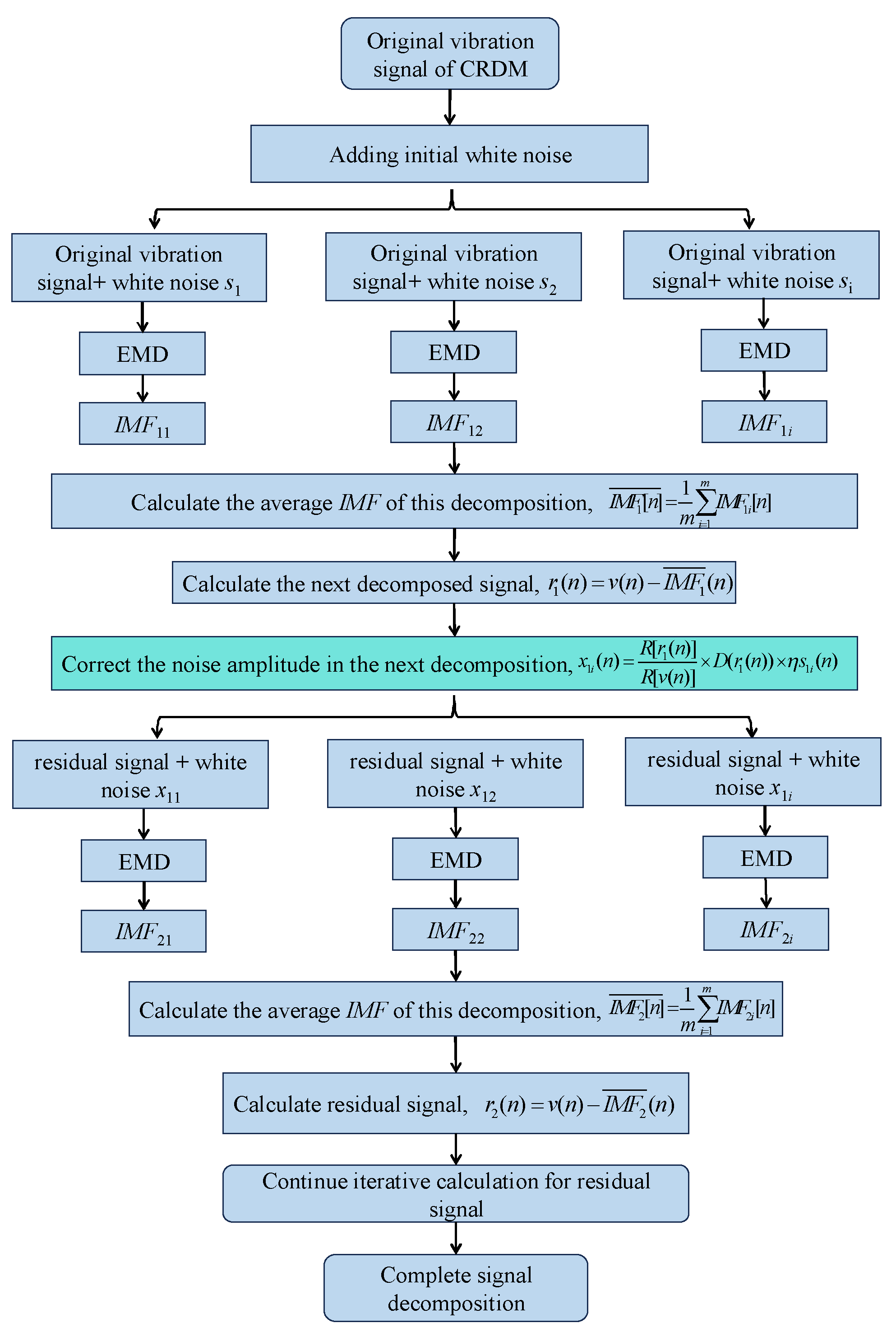
Figure 2.
Noise Reduction Method for Vibration Signal of CRDM.
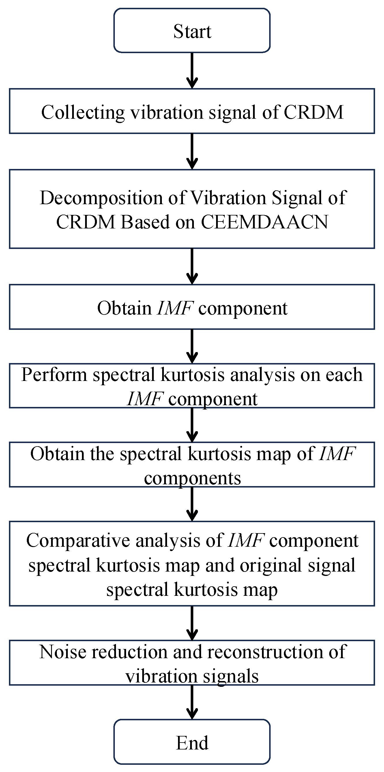
Figure 3.
Vibration acceleration sensors arranged on the outer surface of the pressure housing of CRDM.
Figure 3.
Vibration acceleration sensors arranged on the outer surface of the pressure housing of CRDM.
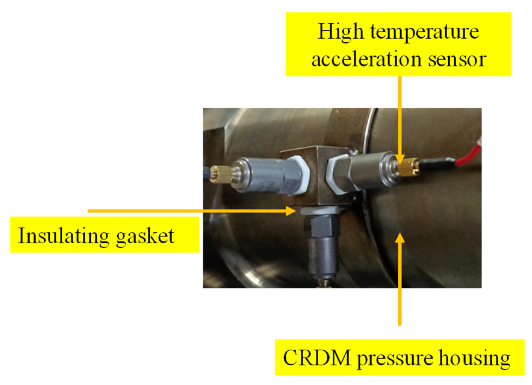
Figure 4.
Experimental data collection system.

Figure 5.
Time domain waveform at the beginning of the life of CRDM.
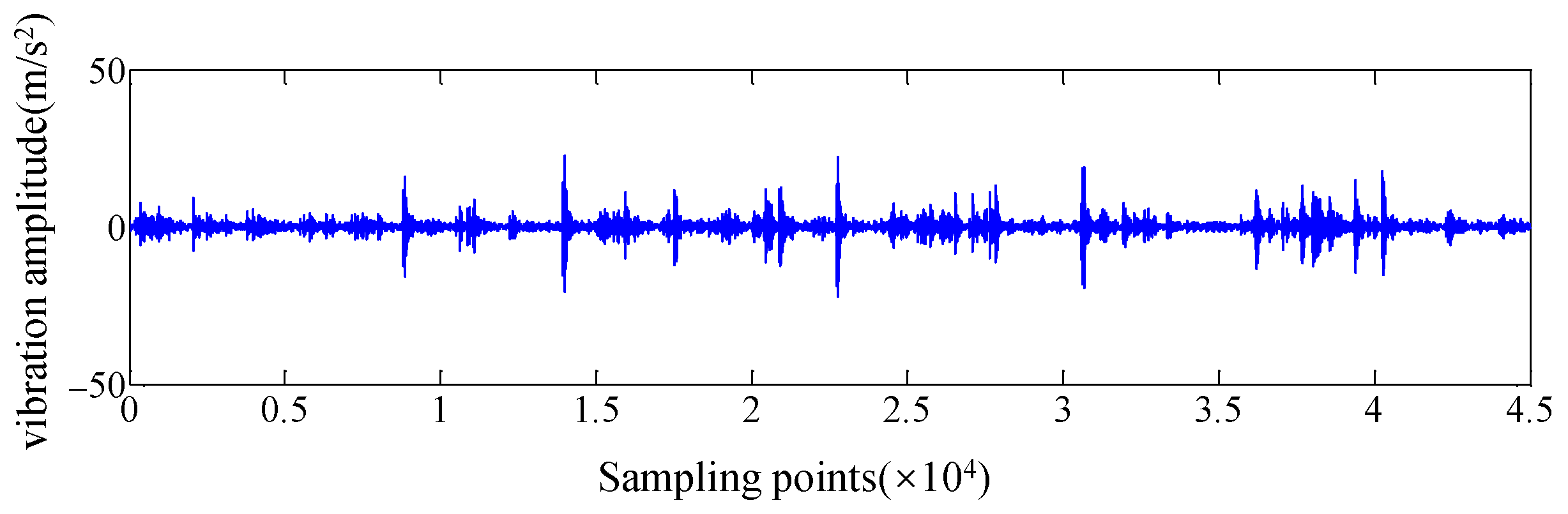
Figure 6.
Time domain waveform at the end of the life of CRDM.
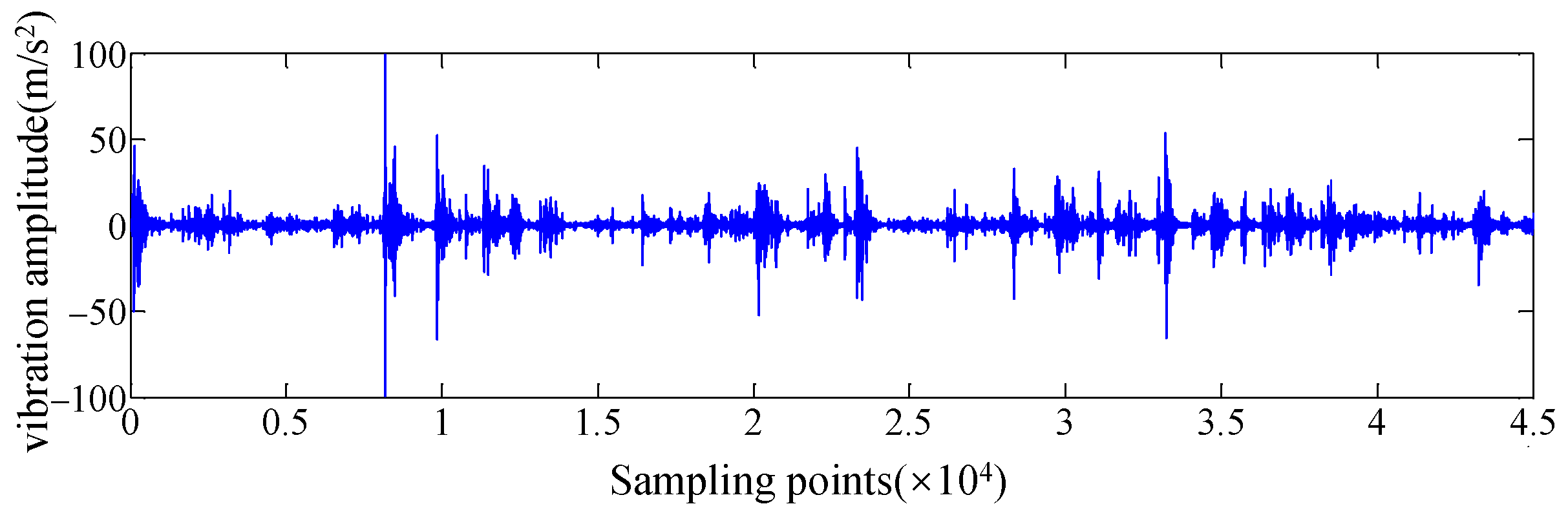
Figure 7.
The spectrum kurtosis of the vibration signal at the end of the service life of CRDM.

Figure 8.
The IMF component waveform of the end-of-life vibration signal of CRDM based on CEEMDAN.
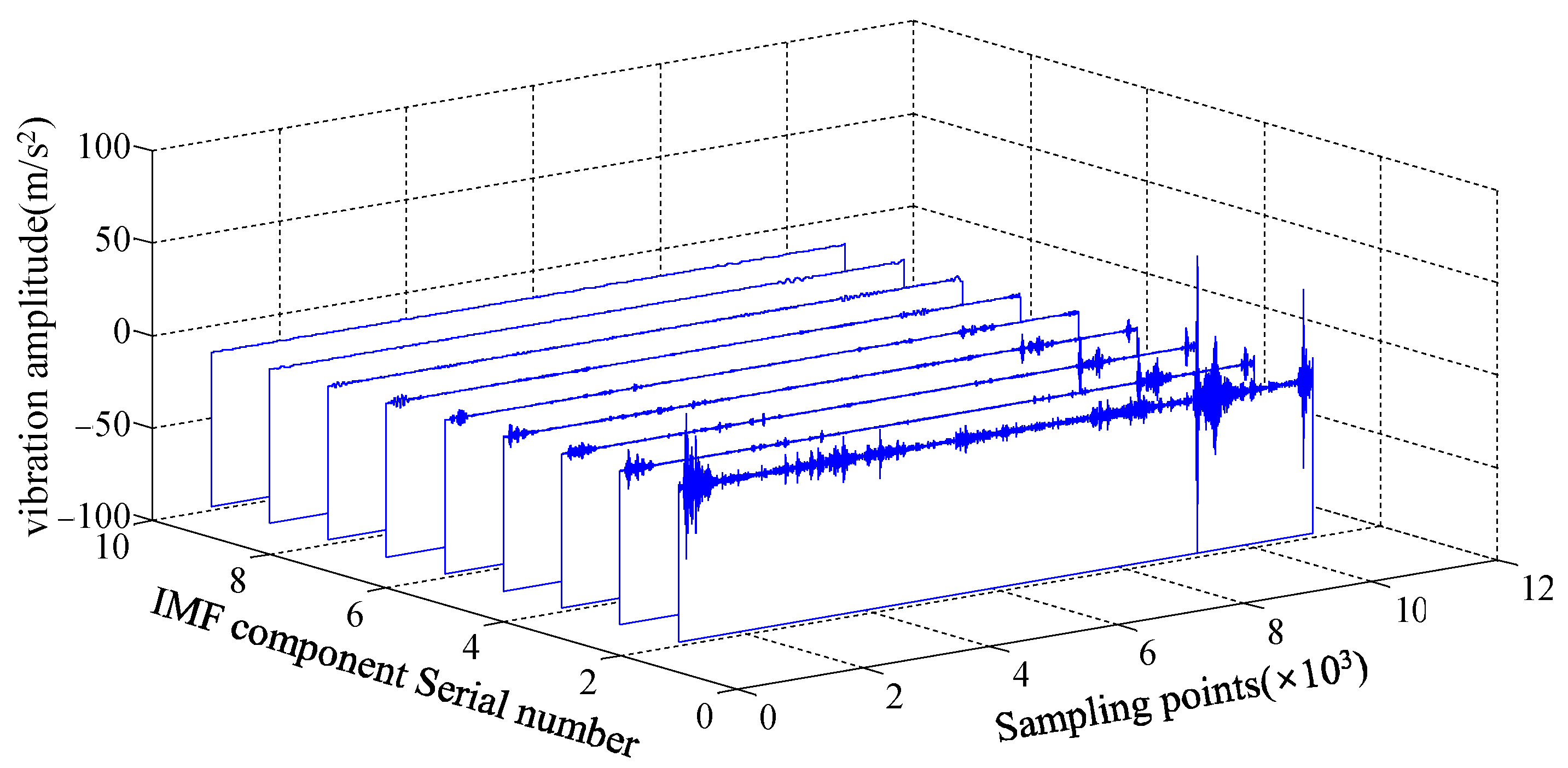
Figure 9.
The IMF component waveform of the end-of-life vibration signal of CRDM based on CEEMDAACN.
Figure 9.
The IMF component waveform of the end-of-life vibration signal of CRDM based on CEEMDAACN.

Figure 10.
The spectral kurtosis diagram of IMF component of end-of-life vibration signal of CRDM based on CEEMDAN.
Figure 10.
The spectral kurtosis diagram of IMF component of end-of-life vibration signal of CRDM based on CEEMDAN.
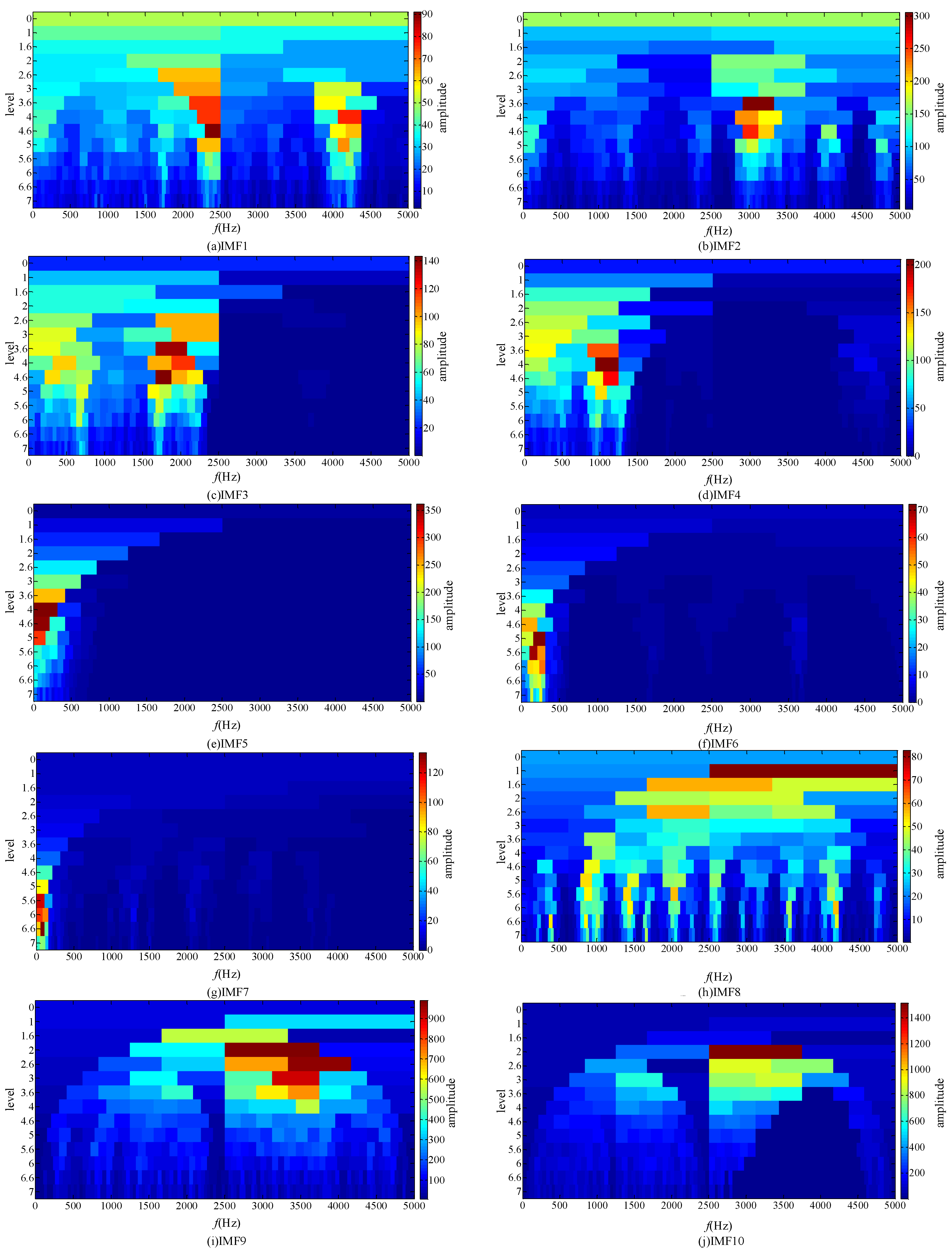
Figure 11.
The spectral kurtosis diagram of IMF component of end-of-life vibration signal of CRDM based on CEEMDAACN.
Figure 11.
The spectral kurtosis diagram of IMF component of end-of-life vibration signal of CRDM based on CEEMDAACN.
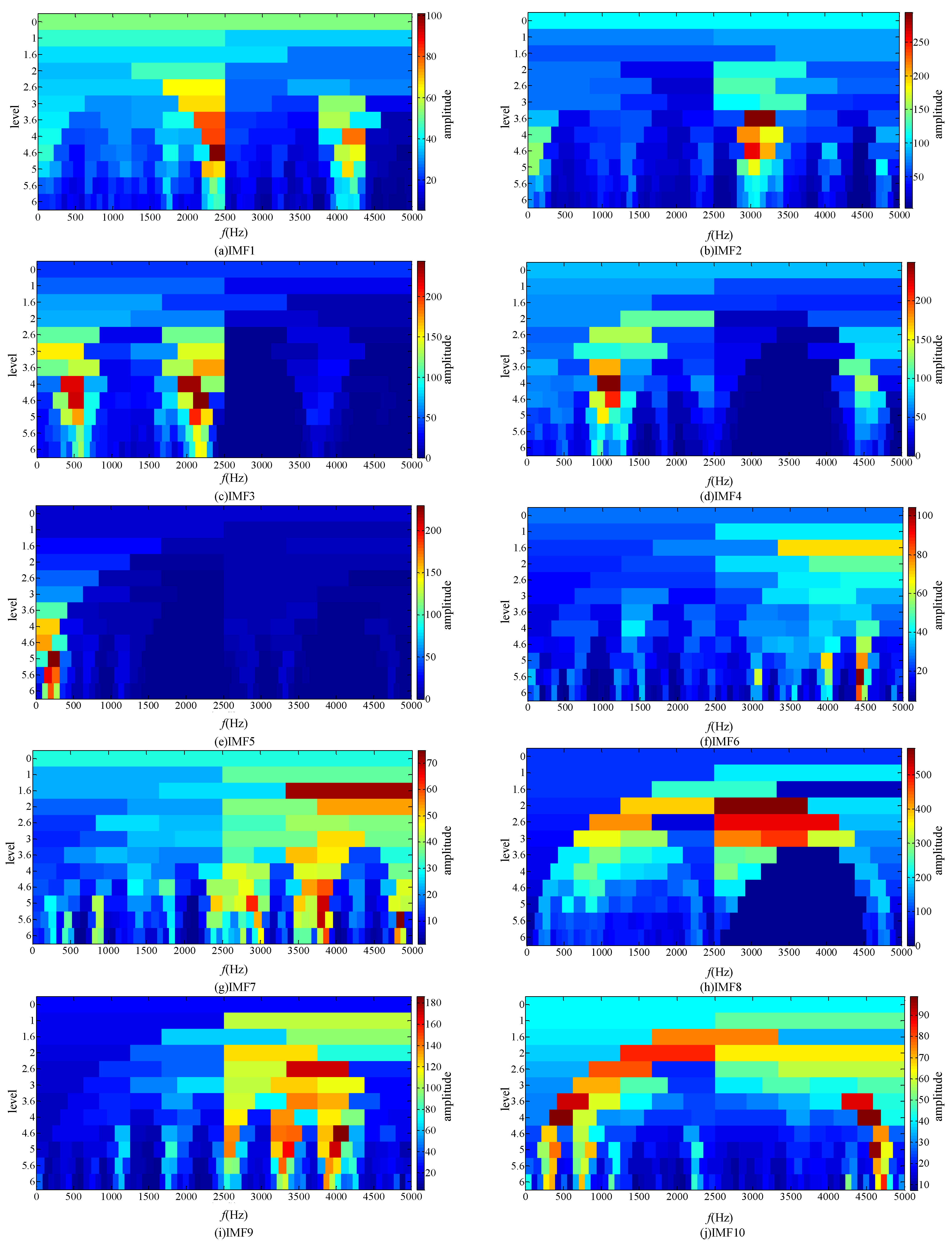
Figure 12.
The signal spectral kurtosis diagram after adding IMF6 and IMF7.


Table 1.
Research progress of CRDM.
| Main References | Research Contents of References | Reference Contribution | Notes |
|---|---|---|---|
| Refs. [1,2,3,4,5,6] | Reliability optimization and design of CRDM | Design reliability of CRDM | Lack of CRDM vibration signal processing and noise reduction technology research |
| Refs. [7,8,9,10] | Reliability and function analysis of CRDM | Function analysis and reliability analysis of CRDM | |
| Refs. [11,12,13,14] | Fault analysis and detection | Robot fault detection, physical degradation analysis and dynamic modeling | |
| Refs. [15,16] | Analysis of rod drop performance | Test and analysis of the performance parameters of CRDM | |
| Refs. [17,18,19,20,21,22,23,24,25,26,27,28,29,30] | Signal noise reduction and application methods in various fields | Signal noise reduction technology | In the existing EEMD, CEEMDAN and other methods, the white noise amplitude added has poor correlation with the signal itself, and the selection criteria of white noise amplitude is not clear enough. |
Table 2.
Performance comparison of two decomposition algorithms.
| Decomposition Algorithm of Vibration Signal | Value of Algorithm Evaluation Index δ |
|---|---|
| CEEMDAN [31,32] | 0.384 |
| CEEMDAACN | 0.088 |
Table 3.
Decomposition results of two algorithms.
| Noise Reduction Method | IMF Component for Signal Reconstruction | Frequency Interval with Maximum Kurtosis Value |
|---|---|---|
| CEEMDAN-SK [35] | IMF8 | 2500–5000 Hz |
| CEEMDAACN-SK | IMF6, IMF7 | 3400–5000 Hz |
Table 4.
Comparison of the results between the proposed method and existing methods.
| LCEEMDAN | LCEEMDAACN | L |
|---|---|---|
| 2500 Hz | 1600 Hz | 36% |
Disclaimer/Publisher’s Note: The statements, opinions and data contained in all publications are solely those of the individual author(s) and contributor(s) and not of MDPI and/or the editor(s). MDPI and/or the editor(s) disclaim responsibility for any injury to people or property resulting from any ideas, methods, instructions or products referred to in the content. |
© 2023 by the authors. Licensee MDPI, Basel, Switzerland. This article is an open access article distributed under the terms and conditions of the Creative Commons Attribution (CC BY) license (https://creativecommons.org/licenses/by/4.0/).
Share and Cite
MDPI and ACS Style
Liu, Z.; Li, T.; Zhu, Z.; Li, M.; Nie, C.; Tang, Z. Noise Reduction Method for the Vibration Signal of Reactor CRDM Based on CEEMDAACN-SK. Electronics 2023, 12, 4681. https://doi.org/10.3390/electronics12224681
AMA Style
Liu Z, Li T, Zhu Z, Li M, Nie C, Tang Z. Noise Reduction Method for the Vibration Signal of Reactor CRDM Based on CEEMDAACN-SK. Electronics. 2023; 12(22):4681. https://doi.org/10.3390/electronics12224681
Chicago/Turabian StyleLiu, Zhilong, Tongxi Li, Zhifeng Zhu, Minggang Li, Changhua Nie, and Zhangchun Tang. 2023. "Noise Reduction Method for the Vibration Signal of Reactor CRDM Based on CEEMDAACN-SK" Electronics 12, no. 22: 4681. https://doi.org/10.3390/electronics12224681
Note that from the first issue of 2016, this journal uses article numbers instead of page numbers. See further details here.