
Modeling of Bacterial Cellulose-Based Composite
by
 , , , , and
Riccardo Caponetto
1,*,†,
Giovanna Di Pasquale
2,†,
Salvatore Graziani
2,†,
Antonino Pollicino
3,†,
Francesca Sapuppo
1,† and
Carlo Trigona
2,*,† 1
Engineering Department, University of Messina, 98158 Messina, Italy
2
Department of Electrical Electronic and Computer Engineering —DIEEI, University of Catania, 95125 Catania, Italy
3
Department of Civil Engineering and Architecture, 95125 Catania, Italy
*
Authors to whom correspondence should be addressed.
†
These authors contributed equally to this work.
Electronics 2023, 12(21), 4530; https://doi.org/10.3390/electronics12214530
Submission received: 30 September 2023
/
Revised: 25 October 2023
/
Accepted: 27 October 2023
/
Published: 3 November 2023
Abstract
:Bio-derived polymers are promising materials for the development of eco-friendly sensors. Composites, composed of bacterial cellulose sheets sandwiched between two layers of conducting polymers and infused with ionic liquids, exhibit generating properties when utilized as deformation sensors. The composite material underwent a frequency analysis to explore the relationship between the transduction property and the frequency of the applied mechanical deformation. A model identification was performed using the acquired experimental data. The linearity of the system was examined, and the findings show that a second-order system, adequately approximates the system’s dynamics.
1. Introduction
The ubiquitous diffusion of electronics poses significant challenges to the environmental sustainability of conventional technologies. Electronic waste (e-waste) is one of the most quickly growing forms of waste on the planet. The total amount of e-waste produced reached approximately 41 million tonnes in 2014 and increases at a rate of 3– every year [1].
Although the presence of precious and rare materials suggests the advantage of e-waste recycling, only a small fraction of e-waste is actually recycled. Even the European Union (EU), which is among the most virtuous actors, is reported to recycle as little as about of e-waste [2].
A significant fraction of e-waste is processed with inadequate procedures or ends up in landfills, with relevant soil consumption and environmental risks.
New technologies and materials are, therefore, required. Polymers have attracted keen interest in implementing new technologies for the realization of unconventional electronics [3,4] because of their attractive properties such as low production costs, lightness, and flexibility. Such properties are partial solutions to the constraints imposed by emerging application fields (wearable electronics, gaming, and augmented reality). Unfortunately, most polymers are not considered green materials because they are not biodegradable, nor can they be disintegrated back into their original materials [5].
A solution to the previous issues is represented by biopolymers, which, while maintaining acceptable performance, are either biodegradable or disintegrable. The most advanced frontier towards this evolution is the realization of transient electronics, whose finite life span and successive degradation are among the designed characteristics [6].
Cellulose has been the most widely investigated biopolymer because of its mechanical and electrical properties, with applications in electronics [7], sensors [8], and actuators [9]. Cellulose is the most abundant biopolymer on Earth [10]; moreover, it is biodegradable. Nevertheless, cellulose is generally derived from vegetable stocks, and its production requires energy- and water-consuming processes. Pollutants can, eventually, be become an undesired side-effect of the pulp industry.
Bacterial cellulose (BC) has recently attracted the interest of researchers as a greener substitute for plant-derived cellulose. Though it has a similar structure to plant-derived cellulose, it is directly produced by some strains of bacteria, such as Acetobacter xylinum in a much purer form [11], provided that a suitable growing environment is guaranteed [12,13]. A further production procedure for BC is based on the cell-free enzyme system [14,15,16].
Typical growing conditions require inoculation of the bacteria into a culturing medium, rich in glucose and yeast. The culture is then incubated at a controlled temperature (about 20–30 ) for several days to allow the production of cellulose. As a result, a pellicle grows at the growing medium–open air interface, whose thickness depends on the growing time. When the cellulose pellicle has reached the desired thickness, it can be harvested by removing it from the growing medium. Washing impurities and bacterial cells from the BC is required. BC sheets are finally obtained after a drying process [17].
Here is a general methodology for the biosynthesis of bacterial cellulose:
- (a)
- Choose a suitable bacterial strain known for its cellulose-producing ability, such as Acetobacter xylinum or other Acetobacter strains;
- (b)
- Prepare a suitable culture medium that typically contains carbon sources (glucose, sucrose), nitrogen sources (ammonium sulfate, yeast extract), mineral salts, and other necessary nutrients;
- (c)
- Inoculate the selected bacterial strain into the prepared culture medium. Allow the bacteria to ferment under controlled conditions (temperature, pH, aeration) for a specific period; during fermentation, bacteria produce cellulose as a protective exopolysaccharide layer;
- (d)
- After the fermentation period, harvest the cellulose pellicle formed at the air–liquid interface of the culture. Carefully remove the pellicle, and wash it to remove bacterial cells and culture medium components;
- (e)
- Treat the harvested cellulose pellicle with alkaline solutions (e.g., sodium hydroxide) to remove residual bacterial cells, hemicellulose, and other impurities; wash the purified cellulose thoroughly with water to neutralize the pH;
- (f)
- Dry the purified bacterial cellulose using methods like freeze-drying or air drying; store the dried bacterial cellulose in a desiccated and airtight container to prevent moisture absorption.
The procedure described above is much less energy- and water-demanding than plant-derived production by the pulp industry. BC is considered more appealing as a green biopolymer than cellulose. As a result, a flourishing body of literature exists on BC-based applications, including electronics and sensor applications [7,18,19,20,21,22].
Ionic liquids (ILs) are a unique class of compounds characterized by their ionic nature in a liquid state at or near room temperature. Unlike most liquids, which consist of molecules with neutral charge, ionic liquids are composed entirely of ions, which are atoms or molecules that have gained or lost electrons, resulting in a net electric charge. These ions can be organic or inorganic, and they typically consist of large, asymmetric cations and various anions. Key characteristics and properties of ionic liquids include melting points below 100 C; lack of volatility, which means they do not readily evaporate into the atmosphere and makes them useful in applications where the control of vapor pressure is essential; and high thermal stability, i.e., they can withstand a wide range of temperatures without decomposing or evaporating. They are often used as electrolytes in batteries and supercapacitors due to their ionic conductivity and are considered more environmentally friendly than many traditional solvents because they produce fewer volatile organic compounds (VOCs) and can often be recycled. 1-Ethyl-3-methylimidazolium tetrafluoroborate EMIM BF4 is an ionic liquid (melting point of 15 C that has gained attention for its versatility in various industrial and research applications. It is composed of a large, asymmetric organic cation (1-ethyl-3-methylimidazolium) and one anion [BF4]-).
Though BC has been widely used for realizing flexible electronics [23,24], and even sensing systems [25,26], the exploitation of BC for realizing piezo-ionic deformation sensors is quite new.
The authors have already investigated BC-based mechanoelectrical transducers [21,22,27,28]. In the sensing applications mentioned above, a three-layer structure consisting of a BC-bulk, with infused ILs and covered by conducting polymer-based electrodes, has been exploited. Such a structure has been revealed to be capable of producing an electrical signal when deformed. More specifically, the authors have investigated the role of charges in the IL in the mechanoelectrical transduction phenomenon [29,30]. Beam structures at very low frequencies and up to the mechanical resonant frequency [21,22] have been investigated.
In this study, the mechanoelectrical transduction properties of BC-based composite were investigated, and a black-box approach was applied to determine a second-order transfer function describing the dynamic relationship between the applied defamation and the measure open circuit voltage.
A pinned pinned beam, which has been deformed by a constant deformation, has been used to this aim. The investigation has been purposefully executed in a frequency range lower than the mechanical resonant frequencies of the beams, in order to avoid any contribution of the mechanical modes of the beams themselves. The used approach allowed for avoiding any influence of the mechanical characteristics of the structure on the recorded signal. The coupling mechanoelectrical transduction capability of the composite in bending mode has been therefore obtained. Finally, black-box models of the frequency response of the bending composite are proposed.
2. Materials and Experimental Setup
The membranes under investigation, which will be examined for their transduction properties and also analyzed from a modeling perspective, have a sandwich structure.
The core consists of BC (by Biofaber), with average thickness ∼395 µm (∼405 µmm as received), width of ∼1 cm, and length of ∼4 cm, that has been was subjected to drying in an oven at 65 C for 4 h to eliminate any water content.
The dried BC was then soaked with EMIM (by Alfa Aesar; see the structure in Figure 1), over a period of 24 h, followed by an additional 24 h drying procedure in a vacuum oven maintained at a controlled temperature of approximately 65 C.
The last step consists of the deposition of electrical contacts (poly (3,4-ethylenedioxythiophene) polystyrene sulfonate (PEDOT:PSS—from H.C. Starck)). on both sides of the BC/IL composite, carried by a 24 µ film spreader.
This process was repeated four times for each side. After each deposition, the samples were dried in oven for five minutes. The final transducer contains about by weight of .
The block scheme of the realized membrane is shown in Figure 2, while in Figure 3 the tested membrane is shown.
In order to characterize the composite, the following experimental setup was considered:
- A shaker (TIRA TV 50009) with its amplifier;
- Two laser distance sensors (Baumer OADM 12U6460/S35A);
- An accelerometer (PCB 333B40);
- A waveform generator (Keysight 33220A);
- An oscilloscope (Keysight MSO9064A);
- Two power supplies (one for the lasers and one for the accelerometer);
- The BC-based composite.
Figure 4 illustrates the block diagram of the setup. In this configuration, a waveform generator applies a known signal to the amplifier, which then drives the shaker. The mechanical vibrations are imparted to the BC, which is fixed at both the anchor (located on the shaker’s plate) and the tip. The primary objective of this analysis is to investigate the system, both through modeling and experimental methods, while maintaining a consistent deformation level with varying frequencies. This study enables the separation of the mechanical response and the electrical response of the BC-based composite. To measure displacement, two lasers are employed to track the movements of the anchor and tip, respectively. The deformation of the beam is calculated as the difference between the positions of the tip and the anchor, utilizing an appropriate transduction function that converts the output voltage into millimeters. Additionally, an accelerometer is utilized as an auxiliary motion sensor, converting the output voltage into acceleration with the aid of a suitable transduction function. The oscilloscope is used to acquire the signals from the two lasers, the accelerometer, and BC. Subsequently, MATLAB® was employed for the post-processing of the acquired data. The experimental setup, along with a zoomed-in view of the tested BC composite, is presented in Figure 5.
3. Modeling
In order to perform the identification of the BC-based composite mechanoelectrical composite in bending configuration, [21,22], a black-box model identification was performed, and a dynamic linear model was considered in the identification procedure.
Starting from the data observation, which will be presented in more detail in the next section, the predicted characteristics of the model, investigated in this study, are the following:
- Two complex and conjugated poles fixed by the values of and : they are responsible for the peak observed in the composite frequency response;
- Two zeros: they are used to fit the module diagram out of the resonance peak;
- A zero in the origin with multiplicity used to fit the module diagram out of the resonance peak;
- A proper gain K.The following transfer function has been, therefore, considered for the identification:and the obtained parameters are listed in Table 1.
In order to determine the model parameters, the following E index error consisting of the sum of two terms has been considered. The first term, , is related to the normalized error between the module of the experimental and the simulated one of Equation (1), while the represents the corresponding error for the phase.
with
Having one zero (with multiplicity 2), two complex and conjugated poles, and a gain as parameters of the transfer function , the identification will consider four parameters. In the next section, a comparison between model identification through genetic algorithms and experiments will be addressed.
4. Identification and Experimental Results
In this section, experimental results regarding the capability to use the BC-based compound to generate voltage for a fixed deformation and by varying the frequency are described. An investigation of the approximation capabilities of Equation (1) is also outlined.
A sinusoidal waveform having a fixed amplitude and variable frequency, in the range 0.25 to 14 , was applied by using the shaker (see Section 2) in order to impose the same deformation for various excitation frequencies.
Part (a) of Figure 6, Figure 7, Figure 8, Figure 9, Figure 10, Figure 11 and Figure 12 shows the mean value of the measurements, the standard deviation, and the model estimation, while Table 1 lists the optimal values for models parameters with different poles/zeros configuration.
For the model identification, a genetic algorithm implemented in MATLAB2022® was run several times to avoid local minima that could lead to poor results in the identification process. For this reason, the error, , was estimated, and, as shown in part (b) of Figure 6, Figure 7, Figure 8, Figure 9, Figure 10, Figure 11 and Figure 12, it tends to converge as generations increase to a minimum value, which does not significantly decrease by increasing the number of generations.
With respect to the and configurations, the results of two different identification procedures, called “limited” and “standard”, are reported. In the standard procedure, the error is computed taking into consideration all measurements, while in the limited one the error from onwards (i.e., after the peak) is considered. In this way, the limited procedure allows a better fitting of the measurements from the peak onwards, which are more relevant than at very-low-frequency ones.
5. Conclusions
In this paper, the model identification and the investigation of the mechanoelectrical transduction properties of bacterial cellulose-based composite have been presented. Analyses were performed with a separation between the mechanical response from the electrical response of the BC. This choice highlights the characteristics of the mechanical–electrical transduction process of the composite when subjected to deflection.
Furthermore, the frequency analysis of the composite was investigated in order to experimentally determine the dependence of the transduction property on the frequency of the applied mechanical deformation. A model identification has been proposed and compared with the experimental data, and considerations concerning the system linearity have also been addressed. The obtained results shown that a second-order system is sufficient to approximate the dynamic of the system. Among the optimized models, the one with one zero in the origin and the two complex poles has shown the better interpolation capability.
Work is in progress with a more exhaustive study and experiments also considering a wider frequency range of analysis. Furthermore, other model structures will be accomplished.
Author Contributions
Conceptualization, R.C., G.D.P., S.G., A.P., F.S. and C.T.; Methodology, R.C., G.D.P., S.G., A.P., F.S. and C.T.; Validation, R.C., G.D.P., S.G., A.P., F.S. and C.T.; Writing—original draft, F.S. All authors contributed equally to this work. All authors have read and agreed to the published version of the manuscript.
Funding
This research received no external funding.
Data Availability Statement
Upon request to corresponding author.
Conflicts of Interest
The authors declare no conflict of interest.
Abbreviations
The following abbreviations are used in this manuscript:
| BC | Bacterial cellulose |
| IL | Ionic liquids |
| PEDOT:PSS | poly (3,4-ethylenedioxythiophene) polystyrene sulfonate |
| EMIM-BF4 | 1-Ethyl-3 methylimidazolium tetrafluoroborate |
References
- Kumar, A.; Holuszko, M.; Espinosa, D. E-waste: An overview on generation, collection, legislation and recycling practices. Resour. Conserv. Recycl. 2017, 112, 32–43. [Google Scholar] [CrossRef]
- Shittu, O.; Williams, I.; Shaw, P. Global E-waste management: Can WEEE make a difference? A review of e-waste trends, legislation, contemporary issues and future challenges. Waste Manag. 2021, 120, 549–563. [Google Scholar] [CrossRef] [PubMed]
- Shahinpoor, M. Ionic Polymer Metal Composites (IPMCs)-Smart Multi-Functional Materials and Artificial Muscles. RSC Smart Mater. 2016, 12, 1. [Google Scholar]
- Lee, C.; Kim, S.; Cho, H. Silk and Paper: Progress and Prospects in Green Photonics and Electronics. Adv. Sustain. Syst. 2022, 6, 2000216. [Google Scholar] [CrossRef]
- Peng, L.; Fu, D.; Qi, H.; Lan, C.; Yu, H.; Ge, C. Micro and nano plastics in marine environment: Source, distribution and threats—A review. Sci. Total Environ. 2020, 698, 134254. [Google Scholar] [CrossRef] [PubMed]
- Jamshidi, R.; Taghavimehr, M.; Chen, Y.; Hashemi, N.; Montazami, R. Transient Electronics as Sustainable Systems: From Fundamentals to Applications. Adv. Sustain. Syst. 2022, 6, 2100057. [Google Scholar] [CrossRef]
- Zhao, D.; Zhu, Y.; Cheng, W.; Chen, Q.; Wu, Q.; Yu, H. Cellulose-Based Flexible Functional Materials for Emerging Intelligent Electronics. Adv. Mater. 2021, 33, 2000619. [Google Scholar] [CrossRef]
- Ummartyotin, S.; Manuspiya, H. A critical review on cellulose: From fundamental to an approach on sensor technology. Ren. Sust. Ener. Rev. 2015, 41, 402–412. [Google Scholar] [CrossRef]
- Ding, L.; Li, X.; Hu, L.; Zhang, Y.; Jiang, Y.; Mao, Y.; Xu, H.; Wang, B.; Feng, X.; Sui, X. A naked-eye detection polyvinyl alcohol/cellulose-based pH sensor for intelligent packaging. Carb. Pol. 2020, 233, 115859. [Google Scholar] [CrossRef]
- McNamara, J.T.; Morgan, J.L.W.; Zimmer, J. A molecular description of cellulose biosynthesis. Annu. Rev. Biochem. 2015, 84, 895–921. [Google Scholar] [CrossRef]
- IqbIqbal, H.; Kyazze, G.; Tron, T.; Keshavarz, T. Laccase-assisted grafting of poly(3-hydroxybutyrate) onto the bacterial cellulose as backbone polymer: Development and characterisation. Carbohydr Polym. 2014, 26, 113. [Google Scholar]
- Iguchi, M.; Yamanaka, S.; Budhiono, A. Bacterial cellulose – a masterpiece of nature’s arts. J. Mat. Sci. 2000, 35, 261–270. [Google Scholar] [CrossRef]
- Mangayil, R.; Rissanen, A.; Pammo, A.; Guizelini, D.; Losoi, P.; Sarlin, E.; Tuukkanen, S.; Santala, V. Characterization of a novel bacterial cellulose producer for the production of eco-friendly piezoelectric-responsive films from a minimal medium containing waste carbon. Cell 2001, 28, 671–689. [Google Scholar] [CrossRef]
- Kim, Y.; Ullah, M.W.; Ul-Islam, M.; Khan, S.; Jang, J.H.; Park, J.K. Self-assembly of bio-cellulose nanofibrils through intermediate phase in a cell-free enzyme system. Biochem. Eng. J. 2019, 142, 135–144. [Google Scholar] [CrossRef]
- Ullah, M.W.; Islam, M.U.; Khan, S.; Shah, N.; Park, J.K. Recent advancements in bioreactions of cellular and cell-free systems: A study of bacterial cellulose as a model. Korean J. Chem. Eng. 2017, 34, 1591–1599. [Google Scholar] [CrossRef]
- Ullah, M.W.; Alabbosh, K.F.; Fatima, A.; Islam, S.U.; Manan, S.; Ul-Islam, M.; Yang, G. Advanced biotechnological applications of bacterial nanocellulose-based nanohybrids: A review. Adv. Ind. Eng. Polym. Res. 2023, 2023, 4. [Google Scholar] [CrossRef]
- Klemm, D.; Cranston, E.D.; Fischer, D.; Gama, M.; Kedzior, S.A.; Kralisch, D.; Kramer, F.; Kondo, T.; Lindström, T.; Nietzsche, S.; et al. Nanocellulose as a natural source for groundbreaking applications in materials science: Today’s state. Mater. Today 2018, 21, 720–748. [Google Scholar] [CrossRef]
- Li, S.; Huang, D.; Zhang, B.; Xu, X.; Wang, M.; Yang, G.; Shen, Y. Flexible Supercapacitors based on bacterial cellulose paper electrodes. Adv. Energy Mater. 2014, 4, 1301655. [Google Scholar] [CrossRef]
- Caponetto, R.; Graziani, S.; Murgano, E.; Trigona, C.; Pollicino, A.; Di Pasquale, G. Modeling of a fractional order element based on bacterial cellulose and ionic liquids. J. Dyn. Syst. Meas. Control Trans. ASME 2021, 143, 071009. [Google Scholar] [CrossRef]
- Caponetto, R.; Di Pasquale, G.; Graziani, S.; Murgano, E.; Pollicino, A. Realization of green fractional order devices by using bacterial cellulose. AEU Int. J. Electron. Commun. 2019, 112, 152927. [Google Scholar] [CrossRef]
- Trigona, C.; Cerruto, S.; Graziani, S.; Di Pasquale, G.; Pollicino, A. Towards environmentally friendly accelerometers based on bacterial cellulose. Appl. Sci. 2021, 119, 7903. [Google Scholar] [CrossRef]
- Di Pasquale, G.; Graziani, S.; Pollicino, A.; Trigona, C. Performance Characterization of a Biodegradable Deformation Sensor Based on Bacterial Cellulose. IEEE Tran. Instr. Meas. 2020, 69, 2561–2569. [Google Scholar] [CrossRef]
- Huang, J.; Zhao, M.; Cai, Y.; Zimniewska, M.; Li, D.; Wei, Q. A Dual-Mode Wearable Sensor Based on Bacterial Cellulose Reinforced Hydrogels for Highly Sensitive Strain/Pressure Sensing. Adv. Electron. Mater. 2020, 6, 1900934. [Google Scholar] [CrossRef]
- Kuswandi, B.; Asih, N.P.; Pratoko, D.K.; Kristiningrum, N.; Moradi, M. Edible pH sensor based on immobilized red cabbage anthocyanins into bacterial cellulose membrane for intelligent food packaging. Packag. Technol. Sci. 2020, 33, 321–332. [Google Scholar] [CrossRef]
- Chen, G.; Liang, X.; Men, X.; Liu, L.; Wang, F.; Bao, X.; Zhang, H. Enhancing thermal conductivity and chemical protection of bacterial cellulose/silver nanowires thin-film for high flexible electronic skin. Int. J. Biol. Macromol. 2023, 229, 422–431. [Google Scholar] [CrossRef]
- Prilepskii, A.; Nikolaev, V.; Klaving, A. Conductive bacterial cellulose: From drug delivery to flexible electronics. Carbohydr. Polym. 2023, 313, 120850. [Google Scholar] [CrossRef]
- Aabloo, A.; Di Pasquale, G.; Graziani, S.; Kurukunda, S.; Pohako-Esko, K.; Pollicino, A.; Trigona, C. A Green Deformation Sensor Based on Bacterial Cellulose and Bio-Derived Ionic Liquids. In Proceedings of the 18th IEEE Int. Multi-Conference Systems, Signals & Devices 2021, Monastir, Tunisia, 22–25 March 2021; pp. 1182–1185. [Google Scholar]
- Di Pasquale, G.; Graziani, S.; Pollicino, A.; Trigona, C. A Bacterial Cellulose Based Mass Sensor. In Proceedings of the International Symposium on Embedded Computing and System Design (ISED), Kollam, India, 8–10 July 2019; p. 8805008. [Google Scholar]
- Di Pasquale, G.; Graziani, S.; Licciulli, A.; Nisi, R.; Pollicino, A.; Trigona, C. Geometrical and thermal influences on a bacterial cellulose-based sensing element for acceleration measurements. Acta IMEKO 2020, 9, 151–156. [Google Scholar]
- Di Pasquale, G.; Graziani, S.; Kurukunda, S.; Pollicino, A.; Trigona, C. Investigation on the role of ionic liquids in the output signal produced by bacterial cellulose-based mechanoelectrical transducers. Sensors 2021, 21, 1295. [Google Scholar] [CrossRef]
Figure 1.
Structure of the Il.
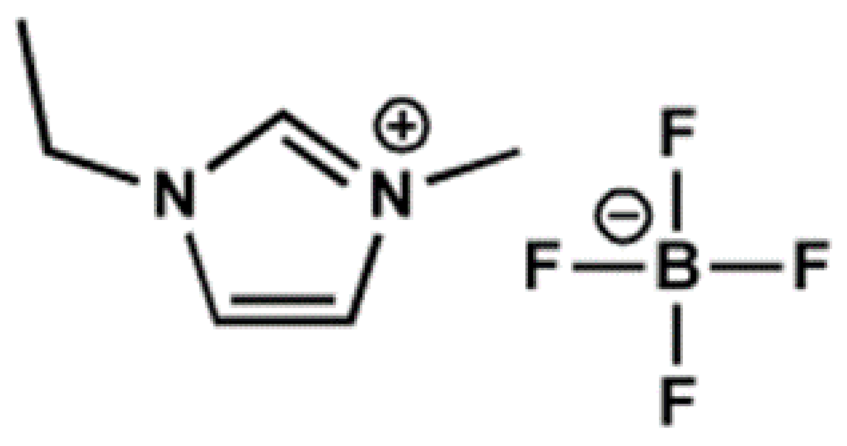
Figure 2.
Block scheme of the bacterial cellulose device.
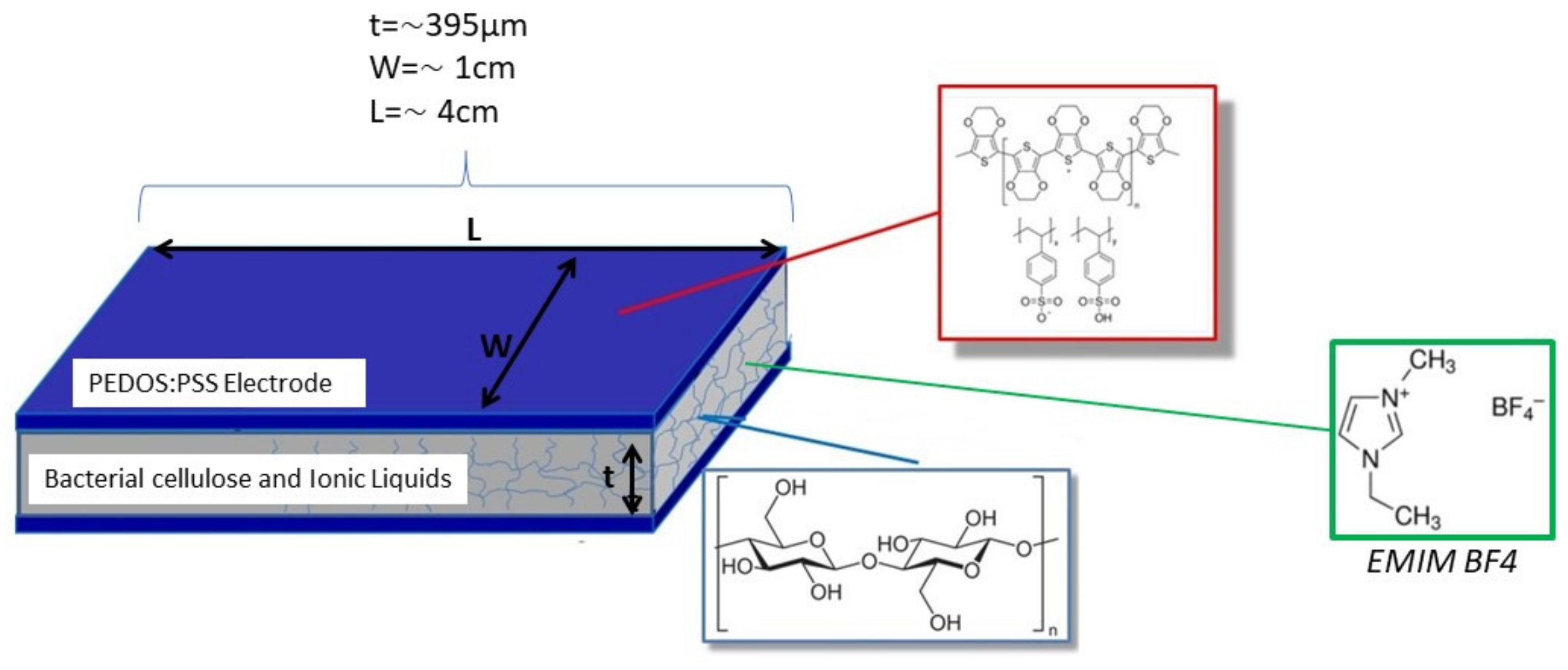
Figure 3.
Fabricated bacterial cellulose device.
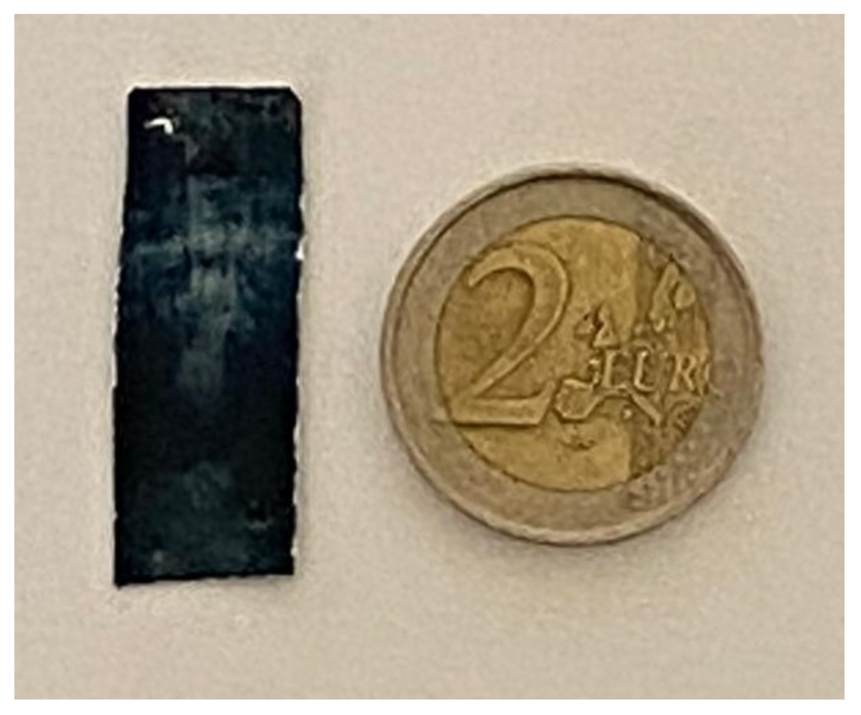
Figure 4.
Block scheme of the experimental setup for the investigation of the BC-based composite and its mechanoelectrical transduction properties.
Figure 4.
Block scheme of the experimental setup for the investigation of the BC-based composite and its mechanoelectrical transduction properties.
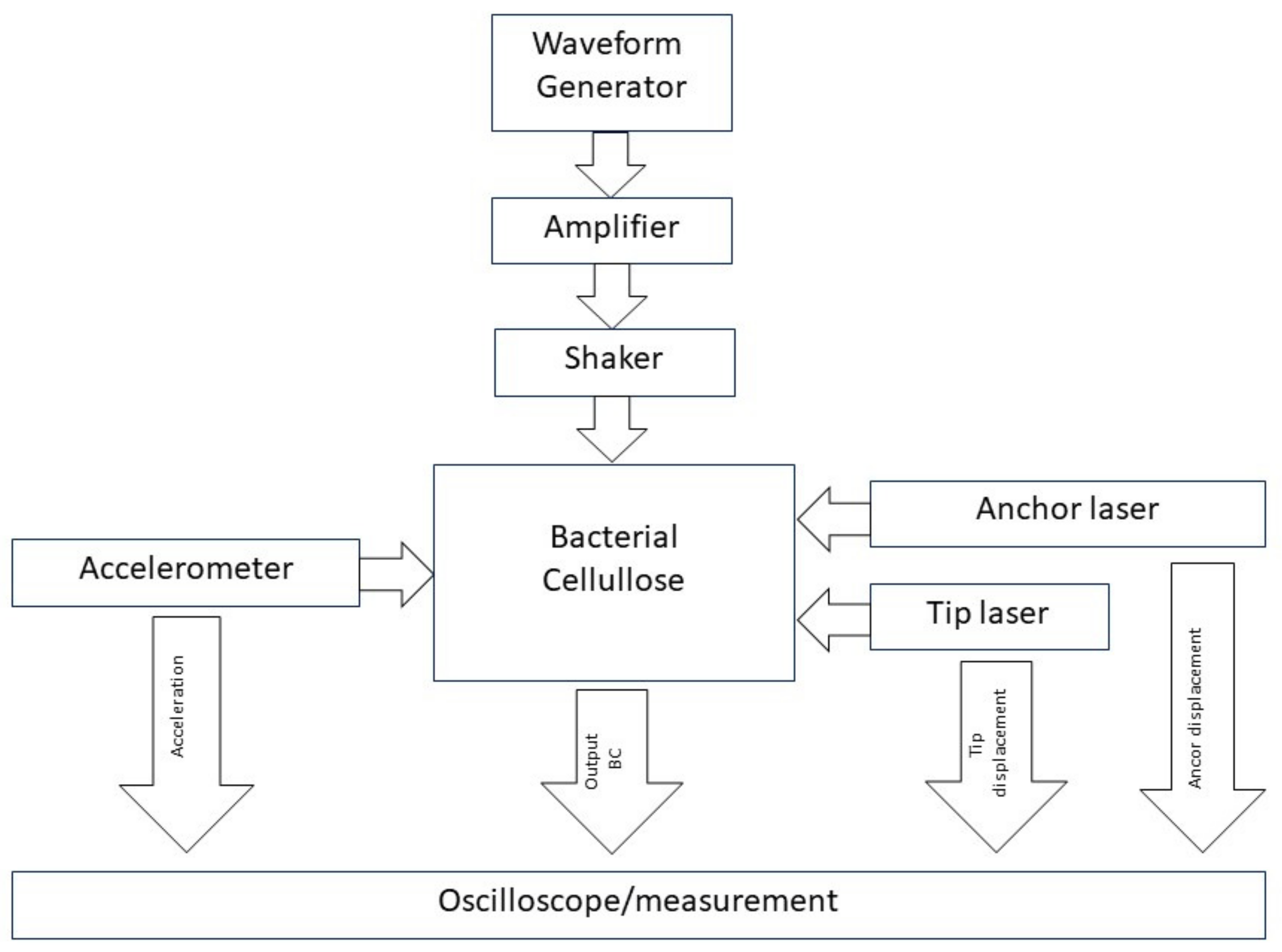
Figure 5.
Laboratory experimental setup: (a) A description of the experimental setup. (b) Detail of the BC under investigation.
Figure 5.
Laboratory experimental setup: (a) A description of the experimental setup. (b) Detail of the BC under investigation.

Figure 6.
configuration. (a) Comparison between the transfer function obtained by using a black-box model and the experimental data. The graph includes the mean values, the transfer function (see (1)), and the standard deviation for each point. (b) Minimum error value evolution in the 100 generations for the black-box identification of the BC-based composite considered.

Figure 7.
configuration. (a) Comparison between the transfer function obtained by using a black-box model and the experimental data. The graph includes the mean values, the transfer function (see (1)), and the standard deviation for each point. (b) Minimum error value evolution in the 100 generations for the black-box identification of the BC-based composite considered.

Figure 8.
configuration. (a) Comparison between the transfer function obtained by using a black-box model and the experimental data. The graph includes the mean values, the transfer function (see (1)), and the standard deviation for each point. (b) Minimum error value evolution in the 100 generations for the black-box identification of the BC-based composite considered.

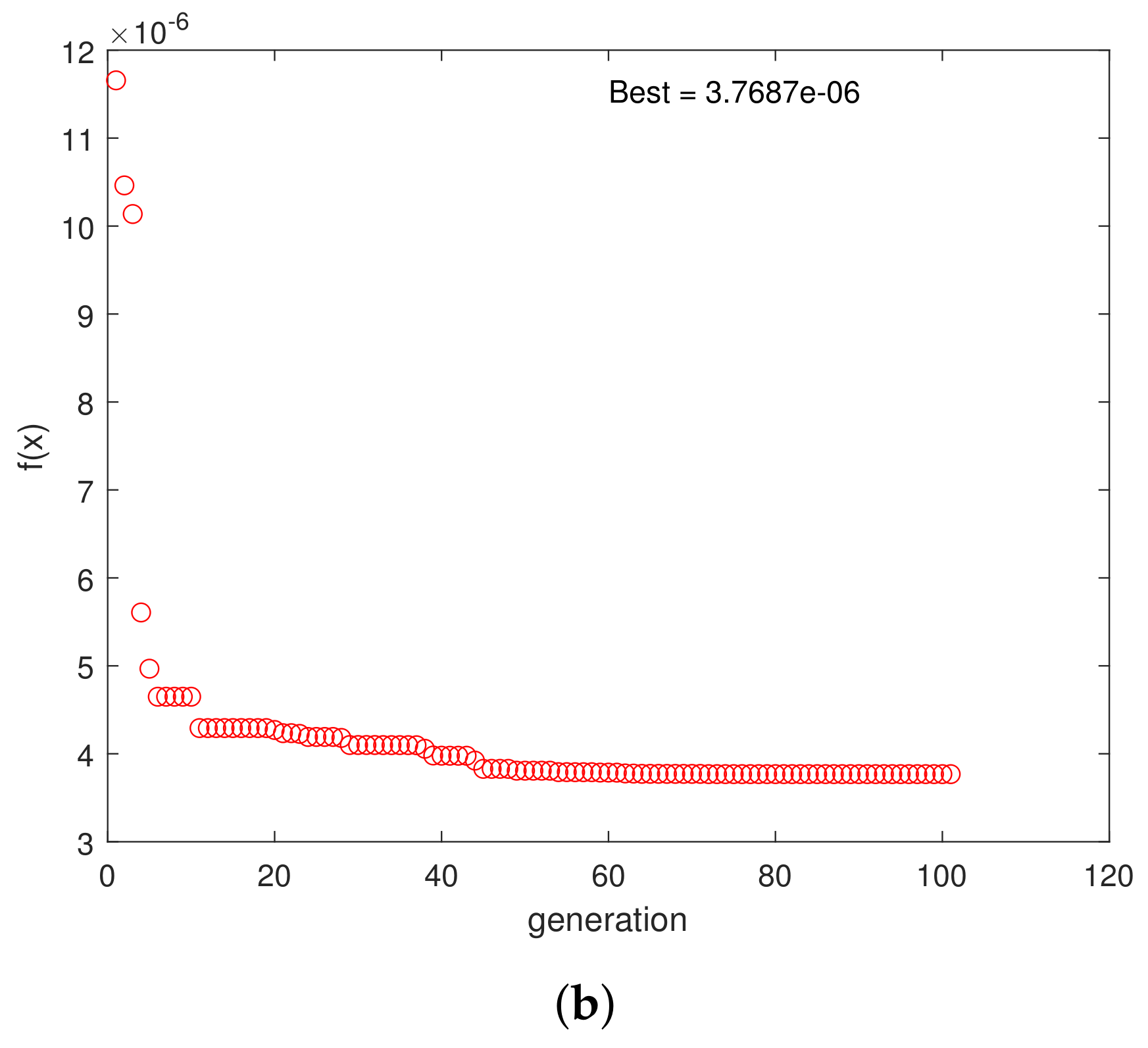
Figure 9.
configuration. Optimization range 3–14 Hz. (a) Comparison between the transfer function obtained by using a black-box model and the experimental data. The graph includes the mean values, the transfer function (see (1)), and the standard deviation for each point. (b) Minimum error value evolution in the 100 generations for the black-box identification of the BC-based composite considered.
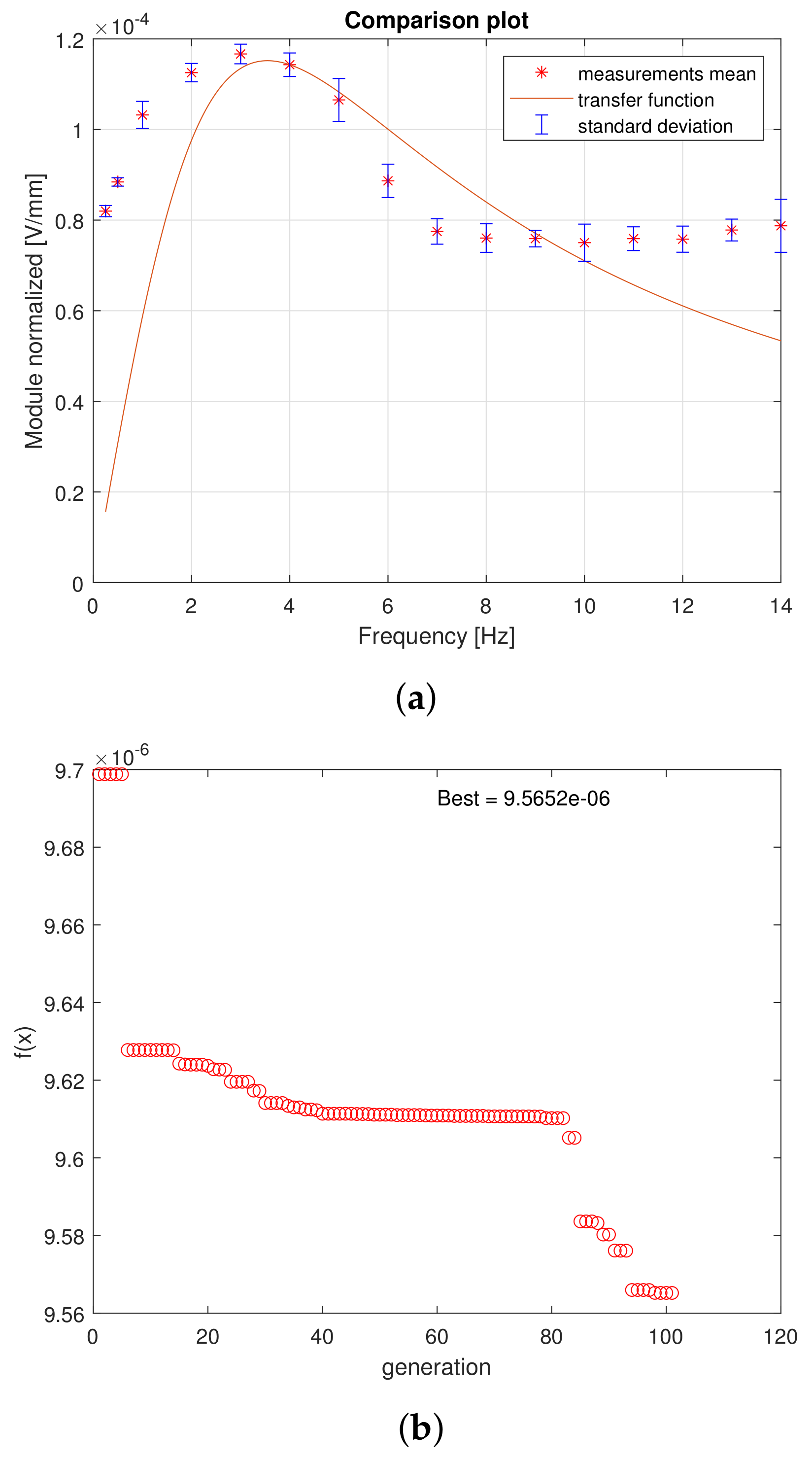
Figure 10.
configuration. All frequencies optimization range. (a) Comparison between the transfer function obtained by using a black-box model and the experimental data. The graph includes the mean values, the transfer function (see (1)), and the standard deviation for each point. (b) Minimum error value evolution in the 100 generations for the black-box identification of the BC-based composite considered.

Figure 11.
configuration. Optimization range 3–14 Hz. (a) Comparison between the transfer function obtained by using a black-box model and the experimental data. The graph includes the mean values, the transfer function (see (1)), and the standard deviation for each point. (b) Minimum error value evolution in the 100 generations for the black-box identification of the BC-based composite considered.
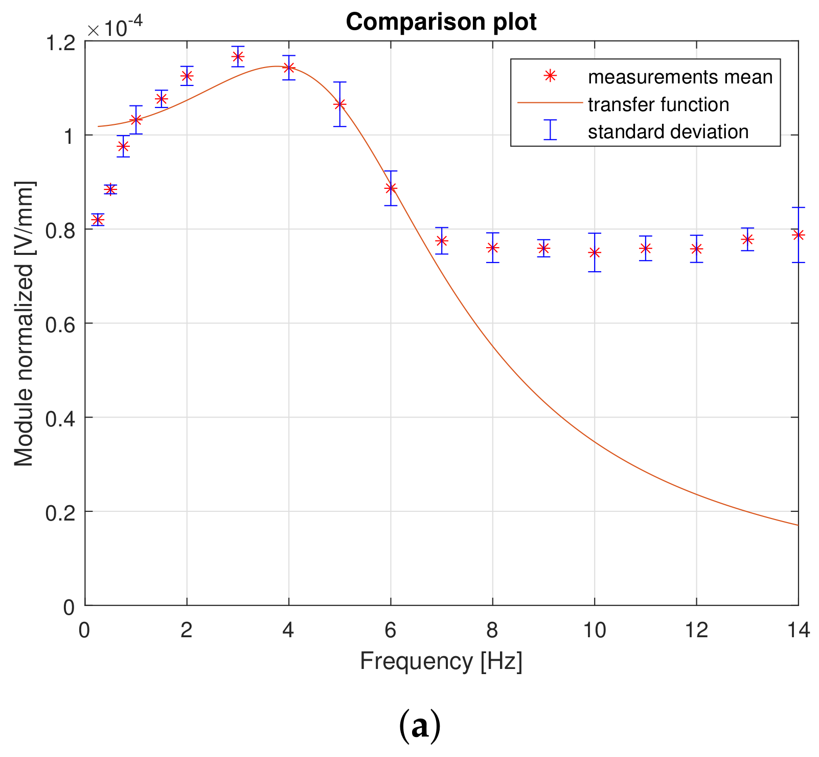
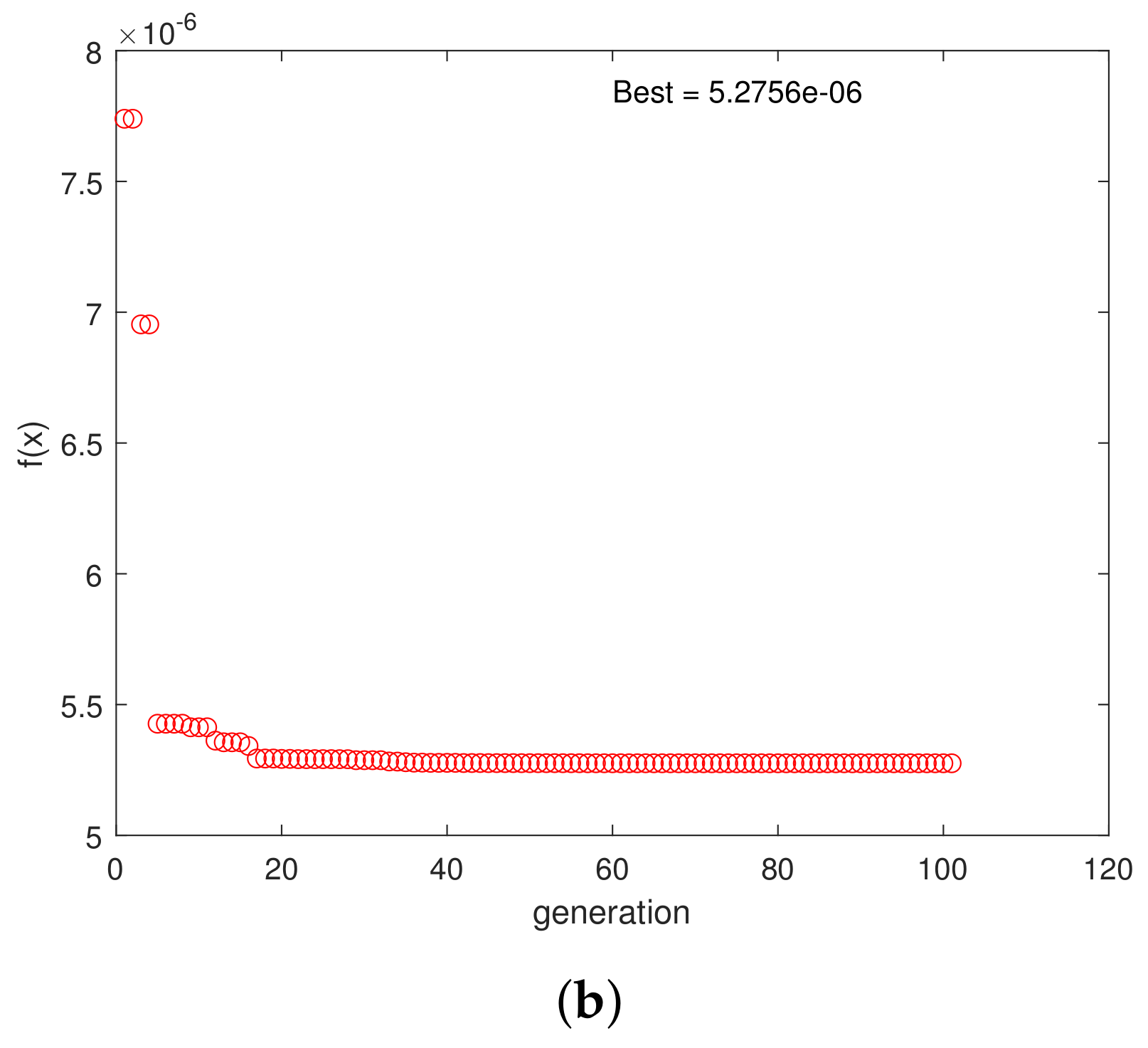
Figure 12.
configuration. All frequencies optimization range. (a) Comparison between the transfer function obtained by using a black-box model and the experimental data. The graph includes the mean values, the transfer function (see (1)), and the standard deviation for each point. (b) Minimum error value evolution in the 100 generations for the black-box identification of the BC-based composite considered.


Table 1.
List of the optimal values for model (1) parameters with different poles/zeros configuration.
Table 1.
List of the optimal values for model (1) parameters with different poles/zeros configuration.
| K | E | ||||||
|---|---|---|---|---|---|---|---|
| 7.60 | 2 | n.c. | n.c. | 0.3054 | 2.1523 | 2.50 | |
| 7.03 | 0 | 3.0720 | 3.0720 | 0.6694 | 2.7440 | 3.75 | |
| 6.94 | 0 | 4.2187 | 2.2886 | 0.6904 | 2.7906 | 3.76 | |
| 7.88 | 1 | n.c. | n.c. | 0.9656 | 3.5461 | 9.56 | |
| 6.81 | 1 | n.c. | n.c. | 0.9800 | 2.8788 | 1.72 | |
| 0.0031 | 0 | n.c. | n.c. | 0.5193 | 5.5470 | 5.27 | |
| 0.0035 | 0 | n.c. | n.c. | 0.5234 | 5.8792 | 1.92 |
Disclaimer/Publisher’s Note: The statements, opinions and data contained in all publications are solely those of the individual author(s) and contributor(s) and not of MDPI and/or the editor(s). MDPI and/or the editor(s) disclaim responsibility for any injury to people or property resulting from any ideas, methods, instructions or products referred to in the content. |
© 2023 by the authors. Licensee MDPI, Basel, Switzerland. This article is an open access article distributed under the terms and conditions of the Creative Commons Attribution (CC BY) license (https://creativecommons.org/licenses/by/4.0/).
Share and Cite
MDPI and ACS Style
Caponetto, R.; Di Pasquale, G.; Graziani, S.; Pollicino, A.; Sapuppo, F.; Trigona, C. Modeling of Bacterial Cellulose-Based Composite. Electronics 2023, 12, 4530. https://doi.org/10.3390/electronics12214530
AMA Style
Caponetto R, Di Pasquale G, Graziani S, Pollicino A, Sapuppo F, Trigona C. Modeling of Bacterial Cellulose-Based Composite. Electronics. 2023; 12(21):4530. https://doi.org/10.3390/electronics12214530
Chicago/Turabian StyleCaponetto, Riccardo, Giovanna Di Pasquale, Salvatore Graziani, Antonino Pollicino, Francesca Sapuppo, and Carlo Trigona. 2023. "Modeling of Bacterial Cellulose-Based Composite" Electronics 12, no. 21: 4530. https://doi.org/10.3390/electronics12214530
Note that from the first issue of 2016, this journal uses article numbers instead of page numbers. See further details here.