Article

Economic Dispatch of Integrated Electricity–Heat–Hydrogen System Considering Hydrogen Production by Water Electrolysis

1
Electric Power Research Institute of State Grid Shanxi Electric Power Company, Taiyuan 030024, China
2
Department of Electrical Engineering, Tsinghua University, Beijing 100084, China
*
Author to whom correspondence should be addressed.
Electronics 2023, 12(19), 4166; https://doi.org/10.3390/electronics12194166
Submission received: 16 August 2023 / Revised: 18 September 2023 / Accepted: 18 September 2023 / Published: 7 October 2023
(This article belongs to the Special Issue Hydrogen and Fuel Cells: Innovations and Challenges)

Abstract

:
Water electrolysis is a clean, non-polluting way of producing hydrogen that has seen rapid development in recent years. It offers the possibility of resolving the issue of excessive carbon emissions in conventional hydrogen production methods. In addition, waste heat recovery in hydrogen fuel cells can significantly increase the efficiency of energy use. Thus, to combine the electric power system, the hydrogen energy system, and the district heating system, this research suggests a novel optimal multi-energy complementary electricity–hydrogen–heat model. Rooftop photovoltaics, energy storage batteries, electric boilers, and hydrogen energy systems made up of hydrogen generation, hydrogen storage, and hydrogen fuel cells are all included in the suggested model. Furthermore, the electricity–hydrogen–heat system can be connected successfully using waste heat recovery in hydrogen fuel cells to create a coordinated supply of heat and power. In this work, the waste heat of hydrogen fuel cells is taken into account to increase the efficiency of energy use. To show the effectiveness of the suggested optimal multi-energy complementary model, many case studies have been conducted.

1. Introduction

Due to the significant environmental problems brought on by the widespread use of fossil fuels, a number of sectors have started to explore low-carbon operating solutions to lower carbon emissions in recent years. The chemical industry, a high-carbon industry, has long been the focus of attention for its carbon emission issue, because the traditional method of producing hydrogen stems from the heavy usage of fossil fuels (such as coal) in the process [1,2].
Because of its pollution-free qualities, hydrogen production by water electrolysis has become more and more popular and is gradually becoming an indispensable technology for green hydrogen preparation [3]. The complementary operation of electricity and hydrogen can be realized by closely coupling the electric power system with the hydrogen energy system to build an electricity–hydrogen integrated energy system. It is possible to realize the complementary electricity–hydrogen operation to reduce energy loss and improve energy utilization [4,5]. A composite fuel cell membrane based on a highly proton-conductive, thermally crosslinkable phenylene sulfonic acid copolymer was prepared by pore filling to improve the efficiency of fuel cells in [3]. Zhang et al. proposed a multi-renewable-to-hydrogen production method for renewable-dominated hydrogen fueling stations [6]. A three-phase hybrid rectifier control method was proposed for high-power electrolytic hydrogen production application in [7]. Meng et al. proposed a hybrid rectifier coordinative control method for realizing multiscale frequency regulation [8]. In addition, Sharma et al. focused on photoactive, stable, and cost-effective materials, presenting the photoelectrochemical characterization of a phosphorus–nitrogen-doped carbon material to study carbon-based materials [9]. In [10,11], an analytical approach based on the least square error method is proposed for estimating the model parameters of the proton exchange membrane under various operating conditions.
To lessen the carbon dioxide emissions of the electricity grid, a new clean energy source called the hydrogen energy system can be deployed. Because it combines the benefits of electricity and hydrogen energy, the integrated electricity–hydrogen energy system is a novel idea. In addition to realizing a clean and efficient distributed energy supply and creating an energy internet with electricity at its core, it is a crucial step toward realizing the stable operation of a significant share of modern energy power systems. Pan et al. proposed a planning model for an electricity–hydrogen energy system considering hydrogen production and storage technologies, thereby solving the problem of randomness and strong seasonal fluctuation of new energy power output [12]. An optimal integrated electric power and hydrogen system strategy that utilizes hydrogen tube trailers for transportation was proposed [13,14]. A hydrogen energy storage system comprising alkaline electrolysis, a proton-exchange membrane fuel cell stack, and a high-pressure hydrogen storage tank with a compressor was proposed [15,16,17]. A multi-stage co-planning model for the power distribution system and hydrogen energy system was developed. Flexible conversion between green power and green hydrogen was realized by the integration of hydrogen energy production, storage, power output, and hydrogenation [16,17,18]. Zhang et al. developed a planning model of hydrogen refueling stations to maximize long-term profitability [19]. Considering hydrogen trading and long-term hydrogen storage, Weiming proposed a new method for the capacity allocation of hydrogen energy collection systems in industrial parks [20]. Wang Dong considered the demand response (DR) of HFCV and studied the operation of the integrated hydrogen system (IPHS) [21]. A coordinated planning model for power system output and transmission (GT) and HSC with transportable seasonal hydrogen storage was proposed in [22]. In order to realize scientific planning of the primary energy supply structure under the concept of carbon neutrality, Pan Xia established a coupled energy and power optimization planning model of electricity–heat–hydrogen–carbon [23]. However, the heat energy generated by hydrogen fuel cells during operation was not considered in the above study. This heat energy can be converted into electricity through a waste heat recovery system, which can improve the overall energy conversion efficiency of the hydrogen fuel cell stack.
This paper aims to develop an economic dispatch strategy of an integrated electric–heat–hydrogen system considering hydrogen production by water electrolysis to achieve a heat-power coordinated supply that can effectively couple the electricity–hydrogen–heat system.
(i)
The proposed model optimizes the allocation of electricity output between rooftop photovoltaics and energy storage batteries to achieve a balance between supply and demand.
(ii)
The model determines the optimal operation strategy for the integrated electric–heat–hydrogen system to minimize the total cost, taking into account the hydrogen production by water electrolysis.
(iii)
The effectiveness of the proposed economic dispatch strategy is verified through simulation studies, demonstrating its potential in achieving an efficient and coordinated supply of electricity and heat in an integrated energy system.
In Section 2, an overview of the proposed electricity–hydrogen–heat multi-energy complementary optimal model is provided. In Section 3, a multi-energy complementary optimal model is presented, which integrated the electric power system and the hydrogen energy system considering the waste heat recovery of hydrogen fuel cells. The results of testing on the simulation system are presented in Section 4. Finally, Section 5 concludes the paper and suggests future work.

2. Electric–Hydrogen–Heat Integrated Energy Systems

To achieve low-carbon operation in industry parks (shown in Figure 1), a low-carbon operation framework of the integrated electric–heat–hydrogen system considering hydrogen production by water electrolysis is proposed. The electricity–hydrogen–heat multi-energy system consists of three closely linked subsystems: the electric power system, the hydrogen energy system and the district heating system. Three subsystems are connected through coupling components (e.g., hydrogen production devices, electric boilers and hydrogen fuel cells). There are two sources of electricity energy in the electric energy system: a power grid and rooftop photovoltaics. The generated electricity is used for electric load, electric storage device and electrolysis of water to produce hydrogen. There are two sources of hydrogen energy in the hydrogen energy system: electrolytic water hydrogen production devices and coal-based hydrogen production devices. The generated hydrogen is used for hydrogen fuel cells and hydrogen storage devices. There are three sources of heating energy in the district heating system: electric boilers, combined heat and power (CHP) units and the waste heat of hydrogen fuel cells. The generated hydrogen is used for heating the load and heating the storage device.
In this paper, the key links and coupling equipment in the electric–hydrogen–heat integrated energy systems are modeled, including the hydrogen source, hydrogen load, energy storage equipment and heat source. The electrolytic water hydrogen production equipment and hydrogen fuel cell are connected to the electric power system and hydrogen energy system. The electric energy generated by the power grid and rooftop photovoltaics is used in producing hydrogen energy in the electrolytic water hydrogen production equipment in the electric–hydrogen–heat integrated energy systems. In the electric power system, the electrolytic water hydrogen production equipment can be regarded as an electricity load. In the hydrogen energy system, it can be regarded as a hydrogen source.
In addition, the waste heat recovery of the hydrogen fuel cell is also connected to the district heating system, the electric power system and the hydrogen energy system. The hydrogen energy generated by electrolytic water hydrogen production devices and coal-based hydrogen production devices is used in producing electric energy. Meanwhile, the waste heat of the hydrogen fuel cell is recovered in the hydrogen fuel cell in the electric–hydrogen–heat integrated energy systems. In the electric power system, the electrolytic water hydrogen production equipment can be regarded as an electricity load. In the district heating system, the waste heat recovery of the hydrogen fuel cell can be regarded as a heating source. In the electric power system, it can be regarded as an electric source. In the hydrogen energy system, it can be regarded as a hydrogen load. Furthermore, the electric boiler connects the electric power system and the district heating system. The electric energy generated by the electric source is used in producing heating energy in the electric boiler. In the electric power system, the electric boilers can be regarded as an electric load. In the district heating energy system, it can be regarded as a heating source.

2.1. Hydrogen Source

2.1.1. Coal-to-Hydrogen Model

Coal reacts with water vapor at high temperature and high pressure to produce hydrogen. In this process, hydrogen production has a linear relationship
m t CTG = η C m t C , t T ,
t = 1 24 m t C = M C , t T ,
The carbon emissions generated in the process of coal hydrogen production can be expressed as follows:
m t CO 2 = η C m t CTG , t T ,
t = 1 24 m t CO 2 = M CO 2 , t T ,

2.1.2. Hydrogen Production from Water Electrolysis Model

Hydrogen production from water electrolysis converts the alternating current of the power grid into direct current through rectification, and it decomposes the water to produce hydrogen through the electrolytic cell. The process can be expressed as follows:
P t DC = η 1 P t AC , m t PTG = η 2 P t DC ρ 0 H LHV , t T ,

2.2. Hydrogen Fuel Cell Model

The waste heat recovery of hydrogen fuel cells can greatly improve energy efficiency and achieve higher output. According to the rule of conservation of energy, its power output and hydrogen consumption conform to the following relationship:
P t HFC = η FC m t HFC H HHV ρ 0 , t T
In addition, the power output and heat production of hydrogen fuel cell conform to the following linear relationship:
h t HFC = a h P t HFC + b h , t T

2.3. Energy Storage Model

Energy storage equipment in the park includes energy storage battery, hydrogen storage tank and heat storage tank. The energy storage equipment model focuses on the storage change process of energy storage equipment, so the energy storage model of the park can be expressed as follows:
E t stor = E t 1 stor + Δ t ( P t 1 cha P t 1 dis ) , t T ,
M t stor = M t 1 stor + Δ t ( m t 1 cha m t 1 dis ) , t T ,
H t stor = H t 1 stor + Δ t ( h t 1 cha h t 1 dis ) , t T ,

2.4. Heat Source

The heat sources include hydrogen fuel cells and electric boilers, of which the electric boiler is a device that directly converts electric energy into heat energy, and there is a linear conversion relationship between electric heat, so its model can be expressed as follows:
h t G = η G P t G , t T ,

3. Low-Carbon Economic Scheduling Model

3.1. Objective Function

In order to minimize park operating costs and reduce carbon emissions, this paper establishes the following objective functions:
min [ t = 1 24 c t E P t t + c m M C + c c M CO 2 ]

3.2. Operation Constraints

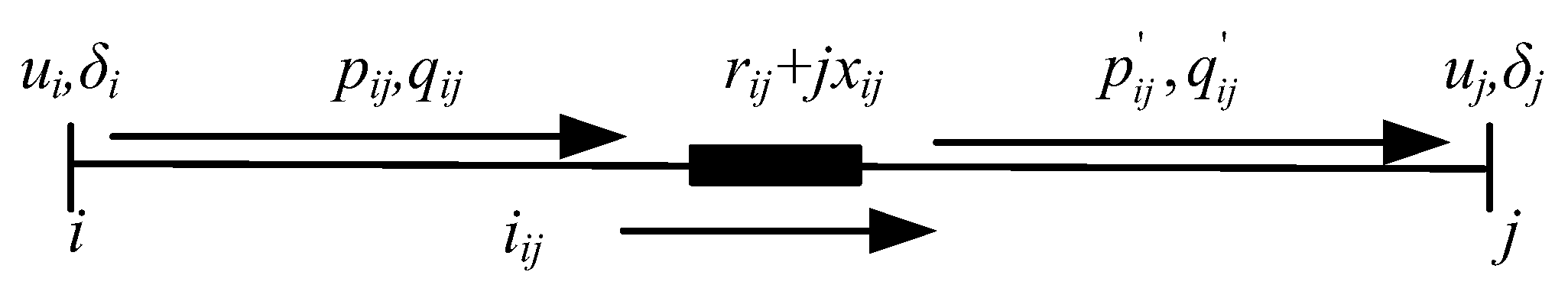
3.2.1. PDS Operation Constraints

A model contains power balance constraints, load-shedding constraints, transmission capacity constraints, voltage drop constraints, and unit output constraints.
  • Power Balance Constraints
p j , t = s δ j p js , t i π ( j ) p ij , t r ij l ij , t , j k bus , t T ,
q j , t = s δ j q js , t i π ( j ) q ij , t x ij l ij , t , j k bus , t T ,
p j , t = p j , t t + p j , t PV + p j , t dis + p j , t HFC p j , t D + p j , t AC + p j , t G + p j , t cha , j k bus , t T ,
q j , t = q j , t t + q j , t PV + q j , t dis + q j , t HFC q j , t D + q j , t AC + q j , t G + q j , t cha , j k bus , t T ,
2 p i j , t   2 q i j , t   l i j , t u i , t 2 l i j , t + u i , t , j k bus , t T ,
2.
Transmission Capacity Constraints
S ¯ i j p ij , t S ¯ i j , ( i , j ) k line , t T ,
S ¯ i j q ij , t S ¯ i j , ( i , j ) k line , t T ,
3.
Voltage Drop Constraints
As shown in Figure 2, the bus voltage will drop along the closed transmission line affected by resistance and reactance, and the bus voltage will not affected by any disconnected bus.
The voltage drop constraints will be described as follows:
u i , c , t u j , c , t 2 r ij p ij , c , t + x ij q ij , c , t + r ij 2 + x ij 2 l ij , c , t = 0 , ( i , j ) k line , t T ,
u ¯ j u j , c , t u ¯ j , j k bus , t T ,
4.
Unit Output Constraints
E min stor E t stor E max stor , 0 p j , c , t cha , p j , c , t dis p max cd ,
0 P t G P max G ,

3.2.2. DHS Operation Constraints

The available heat quantity in the energy flow model is introduced as an auxiliary variable, i.e., h ij = cm ij τ ij S τ ij R , and the energy flow model is applied to the service restoration model. It contains heat station constraints, heat transmission constraints, energy balance constraints, unit output constraints and load-shedding constraints.
5.
Heat Station Constraints
The relationship between the power and heat output of CHP units is expressed as
j k k H F C h j , t HFC + j k k EB h j , t EB + j k k CHP h j , t dis = h k , t HS , k k HS , t T , h j , t HFC = h j , t cha , k k HS , t T ,
6.
Heat Transmission Constraints
Considering the transmission capacity of heating pipelines, the heat energy transmitted though heating pipelines should be limited to a certain range.
h ij , t P , out = h ij , t P , in h ij , t loss , i , j k pipe , t T , c C ,
h ¯ ij P h ij , c , t P , in h ¯ ij P , i , j k pipe , t T , c C ,
h ¯ ij P h ij , c , t P , out h ¯ ij P , i , j k pipe , t T , c C ,
7.
Energy Balance Constraints
The heat energy generated by the heat sources (CHP units and heating boilers) must be used for the heating load.
j , s S j pipe h js , c , t P , o u t + k k j HS h k , c , t HS = h j , c L + i , j S j pipe + h ij , c , t P , in , j k nd , t T , c C ,
8.
Unit Output Constraints
The heating power output of the CHP units and heating boilers must be limited to a certain range due to the unit standards.
H min stor H t stor H max stor , 0 h t cha , h t dis h max cd ,

3.2.3. HS Operation Constraints

  • Hydrogen Source Constraint
The hydrogen output of the electrolytic water hydrogen production devices and coal-based hydrogen production devices must be limited to a certain range.
0 m t CTG m max CTG , 0 m t PTG m max PTG ,
2.
Hydrogen Load Constraints
The hydrogen consumption of the hydrogen load and hydrogen fuel cell should be limited to a certain range.
0 m t H 2 m max H 2 , 0 m t HFC m max HFC
3.
Hydrogen Storage Constraints
M min stor M t stor M max stor , 0 m t cha , m t dis m max cd
4.
Energy Balance Constraint
m t PTG = m t cha , m t CTG + m t dis = m t HFC + m t H 2 ,

4. Case Studies

4.1. Case Description
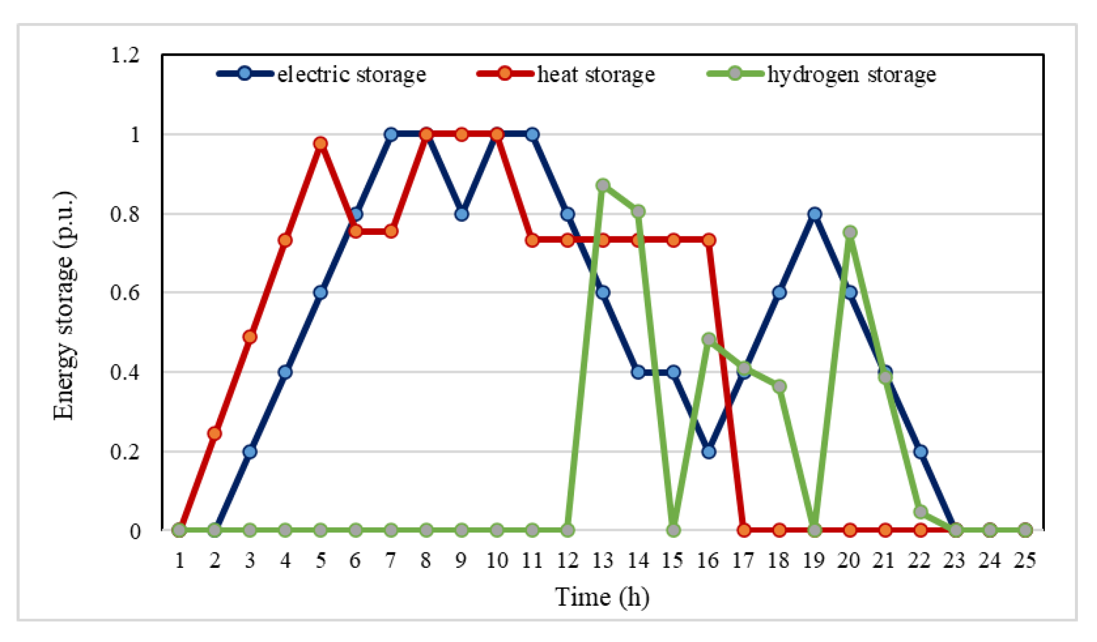
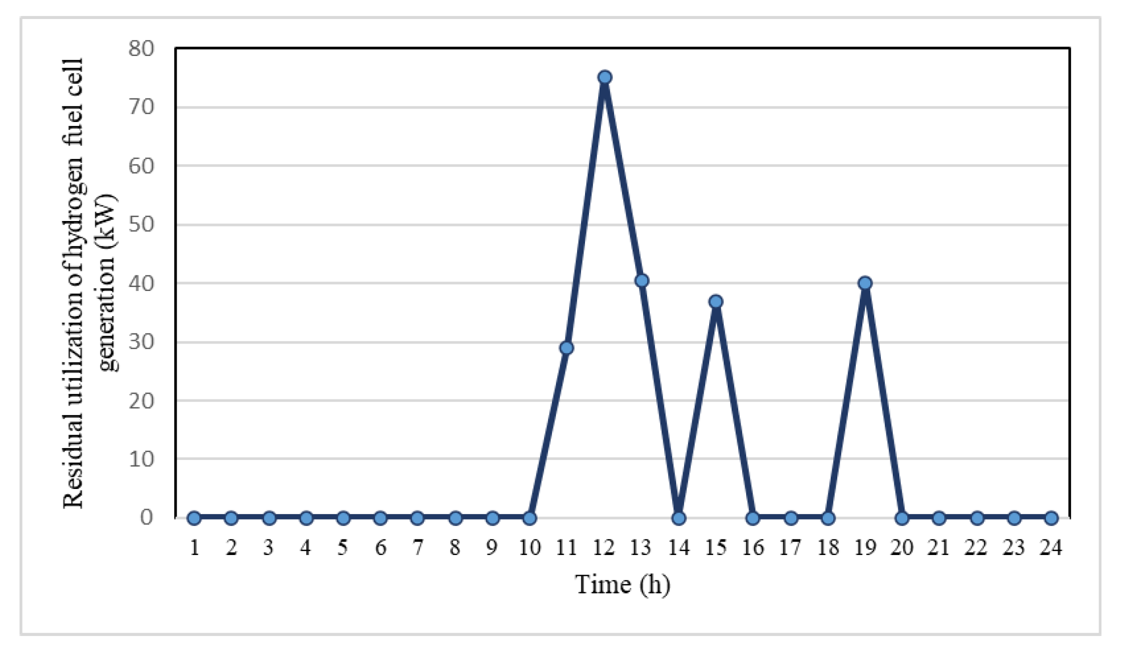
The proposed electric–hydrogen–heat integrated energy systems model is evaluated using a modified actual industrial area in China, which consists of electric boilers, electrolytic water hydrogen production devices, coal-based hydrogen production devices, hydrogen fuel cells, thermal power units, rooftop photovoltaics, an electric load, a heating load, electric storage, heating storage, and hydrogen storage, with precise parameters supplied in [24]. The tests were conducted using Matlab R2020a on a computer with an i7-1165G7 CPU and 16 GB of memory.

4.2. Cases Analysis

The electricity price used in this article is the time-of-use electricity price [25]. Tariffs vary according to the time of day when electricity is used, with tariffs usually higher during peak periods and lower during low periods, as shown in Table 1.
The electric power consumption results of hydrogen production from water electrolysis and hydrogen fuel cell power output are shown in Figure 3, and the operation results of energy storage equipment are shown in Figure 4. Using the time-of-use electricity price, the electrolyzer produces hydrogen at 1:00–7:00 and 23:00–24:00, and it is stored in a hydrogen storage to replace coal to produce hydrogen to supply hydrogen load. The energy storage is charged at 1:00–6:00 and 15:00–19:00, and when the electricity price is high, the energy storage is in a discharge state to supply the load. The hydrogen fuel cell generates electricity at 10:00–14:00, 15:00 and 19:00, and it recovers the waste heat to the heat storage to supply the heat load. The operation results of electric boilers are shown in Figure 5. The electric boilers provide heating at 10:00–14:00, 15:00, and 19:00, which provides heat for the heating load. The consumption of electric load and heating load is shown in Figure 6.
The electricity–hydrogen–heat integrated system realizes the flexible conversion of electricity energy, heat energy and hydrogen energy, which makes full use of the advantages of fast response speed and high energy efficiency of an electric power system and the advantages of suitable energy storage of a heat energy system and hydrogen energy system. Compared to traditional parks that do not introduce photovoltaic, hydrogen, and energy storage batteries, the existence of rooftop photovoltaic, hydrogen energy and energy storage has reduced the daily electricity purchasing cost of the system by $2075, a decrease of 2.4%, reduced coal consumption by 683 kg, a decrease of 1.5%, reduced total cost by $2096, and reduced carbon emissions by 1024 kg. The reason is that the presence of rooftop photovoltaics reduces the power output of thermal power units, thereby reducing the operating costs of thermal power units. Importantly, the carbon emissions can be reduced using the clean energy instead of the fossil energy. The electrolytic water used to produce hydrogen devices reduces the consumption of coal in the process of coal-based hydrogen production and the overall carbon emissions of the system. The role of energy storage is to release energy to ensure user demand when the energy price is high and to store energy when the energy price is low. For example, the electric storage releases electric energy in the period of high electricity price to ensure the consumption of electric load. Charging is performed to store electrical energy when the electricity price is low. Hydrogen storage is also a very large-scale energy storage method which can be used as an electric source for output in buildings, a reliable power source for micro-grids and a backup power source for mobile base stations. However, due to the high operating cost of electrolytic water hydrogen production, the existence of electrolytic water hydrogen production may lead to an increase in the cost of hydrogen energy production. The system operating costs and carbon emissions is shown in Table 2 when the electrolytic cell scale is 600 kW. The effectiveness of the proposed model is verified by the above case.
The system operating costs and carbon emissions when the scale of hydrogen production from electrolyzed water in the system is further expanded are shown in Table 3.
According to Table 2, it can be observed that carbon emissions will decrease as the electrolytic cell’s scale gradually expands. This shows the positive impact of larger electrolytic cells on reducing carbon footprints. There are certain limitations that hinder further expansion of the roof photovoltaic system. One major limitation is the higher electricity purchasing cost compared to the coal purchasing cost. The increasing reliance on electricity purchases would raise the system operating costs, which could have adverse effects on its overall performance and efficiency.
Additionally, the scale of the system also presents a constraint on continual expansion. If the electrolytic cell becomes too large, excessive amounts of electricity would need to be purchased, leading to further increases in system operating costs. These increasing costs could pose challenges to the sustainable and efficient operation of the system. The effectiveness of electric–hydrogen–heat integrated systems has been successfully demonstrated. This suggests that these integrated systems still provide viable solutions for generating clean and renewable energy even if the limitations mentioned above existed.
Moreover, the integration of electric, hydrogen, and heat sources offers diverse benefits, which creates an efficient and interconnected energy framework that allows for the utilization of multiple energy sources simultaneously. By incorporating various energy forms, the system reduces the dependency on conventional fossil fuels and promotes the utilization of cleaner energy. The integration of electric and hydrogen energy contributes to the development of a greener transportation sector, as it enables the use of fuel cells and electric vehicles while minimizing greenhouse gas emissions. Furthermore, the integration of heat sources facilitates the applications in industries that require high-temperature processes, such as steel production or chemical manufacturing.
In conclusion, while the expansion of the electrolytic cell scale leads to a decrease in carbon emissions, some limitations (e.g., high electricity purchasing costs, system size constraints) need to be considered. Nonetheless, the effectiveness and the potential of electric–hydrogen–heat integrated systems in achieving sustainable and clean energy solutions has been proven in this section.

5. Conclusions

In this paper, we propose a novel electricity–hydrogen–heat multi-energy complementary optimal model to integrate the electric power system, the hydrogen energy system and the district heating system. The rooftop photovoltaics, the energy storage batteries devices, the electric boilers, and the hydrogen energy systems consisting of hydrogen production devices, hydrogen storage devices, and hydrogen fuel cells are involved in the proposed model. Moreover, to improve the effectiveness of energy utilization, the waste heat recovery of hydrogen fuel cells is considered in this paper. Numerous case studies are undertaken to demonstrate the effectiveness of a multi-energy complementary optimal model.
For future research, we plan to consider more uncertainties in the electricity–hydrogen–heat multi-energy system. Furthermore, we will explore different ways to improve the effectiveness of energy utilization. In additional, we will also pay attention to coordinated heat and power dispatch (CHPD) with the popularization of CHPD [26,27,28].

Author Contributions

Conceptualization, B.W.; Methodology, B.W.; Data curation, H.G.; Writing—original draft, Z.P., H.Z. and T.X.; Writing—review & editing, Z.P. and H.Z.; Visualization, H.G.; Supervision, J.W. and H.G.; Project administration, J.W., Z.P. and T.X.; Funding acquisition, J.W. All authors have read and agreed to the published version of the manuscript.

Funding

This research is funded by the Science and Technology Project of Shanxi Electric Power Company No. 52053022000K.

Conflicts of Interest

The authors declare no conflict of interest.

Nomenclature

Sets
k i , h CHP / k i , e CHP Index of CHP units i in DHS and PDS
k pipe / k line Set of transmission lines/pipelines
k bus / k bus Set of buses/nodes
π ( j ) / δ j Set of parents and child buses of bus j
k CHP / k HB / k HS Set of CHP units/heating boilers/and heat stations
S j pipe / S j pipe + Set of pipelines flowing from/to node j
Parameters
N s Number of heat/electric sources
N ij Number of pipelines/transmission lines ij
r ij / x ij Binary variable that presents whether there is a fault on line/pipe i , j
l ij Binary variable that presents whether there is a fault on line/pipe i , j
S ¯ i j Transmission capacity of transmission line ( i , j ) (MW)
u ¯ j / u ¯ j Minimum/maximum square voltage magnitude of bus j .(V2)
p ¯ j D G / p ¯ j DG Minimum/maximum power output of DG j (MW)
p ¯ j CHP / p ¯ j CHP Minimum/maximum power output of CHP unit j (MW)
ν _ j / ν ¯ j Minimum/maximum factors of power and heat output of CHP unit j
γ j Factors between heat output and fuel consumption of heating boiler j
h ¯ ij P Maximum transmission capacity of pipelines ( i , j )
a j / b j Weight factors for electric and heat load j (kg)
η C Conversion efficiency of coal to hydrogen
η 1 Efficiency of the rectification process
η 2 Production efficiency of the electrolytic water hydrogen production
ρ 0 Density of hydrogen in the standard states (kg/m3)
H LHV / H HHV Low/high calorific value of hydrogen (J/kg)
η FC Fuel cell power output efficiency
a h / b h Coefficient of the linear function
η G Energy conversion efficiency of the electric boiler
c t E Real-time electricity price at t ($)
c m Price of purchasing coal; ($)
c c Carbon emission penalty coefficient
E max stor / E min stor Upper and lower limits of stored electric energy (kWh)
P max cd Upper limit of charging and discharging power (MW)
P max G Upper limit of the active power input to the electric boiler (MW)
H max stor / H min stor Upper/lower limits of stored heat energy (kWh)
h max cd Upper limit of heat storage tube (kWh)
m max CTG / m max PTG Maximum output of hydrogen production from coal and electrolytic water (kg)
m max H 2 / m max HFC Upper limits of hydrogen ammonia production and hydrogen fuel cell (kg)
M max stor / M min stor Upper and lower limits of stored hydrogen energy (kg)
m max cd Upper limit of charging and discharging hydrogen flow (kg/s)
Variables
m t CTG Mass flow rate of hydrogen production from coal at t (kg)
m t C Mass flow rate of raw coal input at t (kg)
M C Total coal consumption in a scheduling cycle (kg)
m t CO 2 Carbon emission generated by coal hydrogen production at t (kg)
P t AC / P t DC AC and DC power utilized in the electrolytic water hydrogen production at t (MW)
m t PTG Mass flow of hydrogen production at t (kg)
m t HFC Mass flow of hydrogen consumed by the hydrogen fuel cell at t (kg)
P t HFC Fuel cell power output at t (MW)
h t HFC Heat recovered by the hydrogen fuel cell at t (MW)
E t stor / E t 1 stor Stored electric energy at t and t − 1 (kWh)
P t 1 cha / P t 1 dis Input and output active power at t and t − 1 (MW)
M t stor / M t 1 stor Mass of stored hydrogen at t and t − 1 (kg)
m t 1 cha / m t 1 dis Input and output hydrogen flow at t and t − 1 (kg)
H t stor / H t 1 stor Stored heat energy at t and t − 1 (kWh)
h t 1 cha / h t 1 dis Input and output of heat at t − 1 (MW)
P t G / h t G Input active power and heat output of the electric boiler at t (MW)
P t t Electricity purchased by the park at t (MW)
m i , c , t Binary variable that presents whether bus i is divided into faulted regions.
a ij , c , t Binary variables that presents the virtual power flow between buses i and j
σ Binary variable that presents whether SOP is in operation
m i , c , t Binary variable that presents whether bus i is divided into faulted regions.
p j , c , t / q j , c , t Active/Reactive power injection of bus i that is associated with SOP (MW)
p ij , c , t / q ij , c , t Active/Reactive power flow from bus i to bus j (MW)
p j , c , t DG / q j , c , t DG Active/Reactive power output of DG at bus i (MW)
p j , c , t CHP / q j , c , t CHP Active/Reactive power output of CHP unit at bus i (MW)
p j , c , t L / q j , c , t L Electric demand of bus j (MW)
p j , c , t Loss / q j , c , t Loss Load shedding of bus j (MW)
u i , c , t Square voltage of bus j (V)
h j , c , t CHP Heat output of CHP unit j (MW)
h j , c , t HB / f j , c , t HB Heat output and fuel consumption of heating boiler j (MW)
h k , c , t HS Heat output of heat station k (MW)
h ij , c , t P , out / h ij , c , t P , in / h ij , c , t loss Outlet/inlet/loss heat quantity of pipe ( i , j ) (MW)

References

  1. Cai, G.; Kong, L. Techno-economic analysis of wind curtailment/hydrogen production/fuel cell vehicle system with high wind penetration in China. CSEE J. Power Energy Syst. 2017, 3, 44–52. [Google Scholar] [CrossRef]
  2. Ahmad, J.; Imran, M.; Ali, S.F.; Adnan, M.; Ashraf, S.R.; Hussain, Z.; Shoaib, M. Wind-to-Hydrogen Production Potential for Selected Sites in Pakistan. IEEE Access 2021, 9, 134874–134898. [Google Scholar] [CrossRef]
  3. Shang, Z.; Hossain, M.M.; Wycisk, R.; Pintauro, P.N. Poly(phenylene sulfonic acid)-expanded polytetrafluoroethylene composite membrane for low relative humidity operation in hydrogen fuel cells. J. Power Sources 2022, 535, 231375. [Google Scholar] [CrossRef]
  4. Ursua, A.; Gandia, L.M.; Sanchis, P. Hydrogen Production From Water Electrolysis: Current Status and Future Trends. Proc. IEEE 2012, 100, 410–426. [Google Scholar] [CrossRef]
  5. Iribarren, Á.; Elizondo, D.; Barrios, E.L.; Ibaiondo, H.; Sanchez-Ruiz, A.; Arza, J.; Sanchis, P.; Ursúa, A. Dynamic Modeling of a Pressurized Alkaline Water Electrolyzer: A Multiphysics Approach. IEEE Trans. Ind. Appl. 2023, 59, 3741–3753. [Google Scholar] [CrossRef]
  6. Zhang, K.; Zhou, B.; Or, S.W.; Li, C.; Chung, C.Y.; Voropai, N. Optimal Coordinated Control of Multi-Renewable-to-Hydrogen Production System for Hydrogen Fueling Stations. IEEE Trans. Industry Appl. 2022, 58, 2728–2739. [Google Scholar] [CrossRef]
  7. Meng, X.; Chen, M.; He, M.; Wang, X.; Liu, J. A Novel High Power Hybrid Rectifier With Low Cost and High Grid Current Quality for Improved Efficiency of Electrolytic Hydrogen Production. IEEE Trans. Power Electron. 2022, 37, 3763–3768. [Google Scholar] [CrossRef]
  8. Meng, X.; Jiang, L.; He, M.; Wang, X.; Liu, J. A Novel Multi-Scale Frequency Regulation Method of Hybrid Rectifier and Its Specific Application in Electrolytic Hydrogen Production. IEEE Trans. Power Electron. 2023, 38, 123–129. [Google Scholar] [CrossRef]
  9. Sharma, R.; Arnoult, K.; Ramasahayam, S.K.; Azam, S.; Hicks, Z.; Shaikh, A.; Viswanathan, T. Photoelectrochemical Hydrogen Production Using Novel Heteroatom-Doped Carbon Under Solar Simulated Radiation. IEEE Trans. Ind. Appl. 2016, 52, 378–383. [Google Scholar] [CrossRef]
  10. Abomazid, A.M.; El-Taweel, N.A.; Farag, H.E.Z. Novel Analytical Approach for Parameters Identification of PEM Electrolyzer. IEEE Trans. Ind. Inform. 2022, 18, 5870–5881. [Google Scholar] [CrossRef]
  11. Mazumder, M.; Horenstein, M.N.; Stark, J.W.; Girouard, P.; Sumner, R.; Henderson, B.; Sadder, O.; Hidetaka, I.; Biris, A.S.; Sharma, R. Characterization of Electrodynamic Screen Performance for Dust Removal from Solar Panels and Solar Hydrogen Generators. IEEE Trans. Ind. Appl. 2013, 49, 1793–1800. [Google Scholar] [CrossRef]
  12. Pan, G.; Gu, W.; Lu, Y.; Qiu, H.; Lu, S.; Yao, S. Optimal Planning for Electricity-Hydrogen Integrated Energy System Considering Power to Hydrogen and Heat and Seasonal Storage. IEEE Trans. Sustain. Energy 2020, 11, 2662–2676. [Google Scholar] [CrossRef]
  13. Shao, C.; Feng, C.; Shahidehpour, M.; Zhou, Q.; Wang, X.; Wang, X. Optimal Stochastic Operation of Integrated Electric Power and Renewable Energy With Vehicle-Based Hydrogen Energy System. IEEE Trans. Power Syst. 2021, 36, 4310–4321. [Google Scholar] [CrossRef]
  14. Clegg, S.; Mancarella, P. Integrated Modeling and Assessment of the Operational Impact of Power-to-Gas (P2G) on Electrical and Gas Transmission Networks. IEEE Trans. Sustain. Energy 2015, 6, 1234–1244. [Google Scholar] [CrossRef]
  15. Li, J.; Li, G.; Ma, S.; Liang, Z.; Li, Y.; Zeng, W. Modeling and Simulation of Hydrogen Energy Storage System for Power-to-gas and Gas-to-power Systems. J. Mod. Power Syst. Clean Energy 2023, 11, 885–895. [Google Scholar] [CrossRef]
  16. Gómez-Villarreal, H.; Cañas-Carretón, M.; Zárate-Miñano, R.; Carrión, M. Output Capacity Expansion Considering Hydrogen Power Plants and Energy Storage Systems. IEEE Access 2023, 11, 15525–15539. [Google Scholar] [CrossRef]
  17. Sun, Q.; Wu, Z.; Gu, W.; Liu, P.; Wang, J.; Lu, Y.; Zheng, S.; Zhao, J. Multi-stage Co-planning Model for Power Distribution System and Hydrogen Energy System Under Uncertainties. J. Mod. Power Syst. Clean Energy 2023, 11, 80–93. [Google Scholar] [CrossRef]
  18. Gong, X.; Dong, F.; Mohamed, M.A.; Abdalla, O.M.; Ali, Z.M. A Secured Energy Management Architecture for Smart Hybrid Microgrids Considering PEM-Fuel Cell and Electric Vehicles. IEEE Access 2020, 8, 47807–47823. [Google Scholar] [CrossRef]
  19. Zhang, J.; Li, C.; Chen, G.; Dong, Z. Planning of Hydrogen Refueling Stations in Urban Setting While Considering Hydrogen Redistribution. IEEE Trans. Ind. Appl. 2022, 58, 2898–2908. [Google Scholar] [CrossRef]
  20. Luo, W.; Wu, J.; Cai, J.; Mao, Y.; Chen, S. Capacity Allocation Optimization Framework for Hydrogen Integrated Energy System Considering Hydrogen Trading and Long-Term Hydrogen Storage. IEEE Access 2023, 11, 15772–15787. [Google Scholar]
  21. Dong, W.; Shao, C.; Feng, C.; Zhou, Q.; Bie, Z.; Wang, X. Cooperative Operation of Power and Hydrogen Energy Systems with HFCV Demand Response. IEEE Trans. Ind. Appl. 2022, 58, 2630–2639. [Google Scholar] [CrossRef]
  22. Jiang, H.; Qi, B.; Du, E.; Zhang, N.; Yang, X.; Yang, F.; Wu, Z. Modeling Hydrogen Supply Chain in Renewable Electric Energy System Planning. IEEE Trans. Industry Appl. 2022, 58, 2780–2791. [Google Scholar] [CrossRef]
  23. Xia, P.; Chen, H.; Yuan, B.; Zhang, J.; Wu, C.; Gong, Y. Study on Optimization Method of Energy and Power Path toward Dual Carbon Goal Considering Electricity-Heat-Hydrogen-Carbon Coupling. In Proceedings of the 2023 5th Asia Energy and Electrical Engineering Sympo-Sium, Chengdu, China, 23–26 March 2023; pp. 708–713. [Google Scholar]
  24. Li, J.; Lin, J.; Song, Y.; Xing, X.; Fu, C. Operation Optimization of Power to Hydrogen and Heat (P2HH) in ADN Coordinated With the District Heating Network. IEEE Trans. Sustain. Energy 2019, 10, 1672–1683. [Google Scholar] [CrossRef]
  25. “Test Data for Economic Dispatch of Integrated Electric-Heat-Hydrogen System Considering Hydrogen Production by Water Electrolysis in Matlab Format”. 2023. Available online: https://www.jianguoyun.com/p/DQS4g6UQ8bv3Cxj46ZkFIAA (accessed on 15 August 2023).
  26. Wang, K.; Xue, Y.; Guo, Q.; Shahidehpour, M.; Zhou, Q.; Wang, B.; Sun, H. A Coordinated Reconfiguration Strategy for Multi-Stage Resilience Enhancement in Integrated Power Distribution and Heating Networks. IEEE Trans. Smart Grid. 2023, 14, 2709–2722. [Google Scholar] [CrossRef]
  27. Zhao, L.; Xue, Y.; Sun, H.; Du, Y.; Chang, X.; Su, J.; Li, Z. Benefit allocation for combined heat and power dispatch considering mutual trust. Appl. Energy 2023, 345, 121279. [Google Scholar] [CrossRef]
  28. Du, Y.; Xue, Y.; Wu, W.; Shahidehpour, M.; Shen, X.; Wang, B.; Sun, H. Coordinated Planning of Integrated Electric and Heating System Considering the Optimal Reconfiguration of District Heating Network. IEEE Trans. Power Syst. 2023, 3242652. [Google Scholar] [CrossRef]
Figure 1. Electricity–hydrogen–heat multi-energy system structure.
Electronics 12 04166 g001
Figure 2. Voltage drop along a transmission line.
Electronics 12 04166 g002
Figure 3. Operation results of electrolyzer and hydrogen fuel cell.
Electronics 12 04166 g003
Figure 4. Operation results of energy storage device.
Electronics 12 04166 g004
Figure 5. Operation results of electric boiler.
Electronics 12 04166 g005
Figure 6. Operation results of electric load and heating load.
Electronics 12 04166 g006
Table 1. Time-of-use electricity price.
Time IntervalTimePrice ($)
High hours11:00–15:00, 19:00–22:001.08
Low hours1:00–7:00, 23:00–24:000.36
other8:00–10:00, 16:00–18:000.73
Table 2. System operating costs and carbon emissions when electrolytic cell scale is 600 kW.
Electricity Purchasing Cost ($)Coal Purchasing Cost ($)Total Cost ($)Carbon Emissions (kg)
Traditional model87,84640,335127,59766,018
Proposed model85,77139,739125,51064,994
Table 3. System operating costs and carbon emissions.
Electrolyzer Scale (kW)Electricity Purchasing Cost ($)Coal Purchasing Cost ($)Total Cost ($)Carbon Emissions (kg)
60085,77139,739125,51064,994
80086,41939,492125,91164,590
100087,06739,245126,31364,187
120087,71538,999126,71463,784
Disclaimer/Publisher’s Note: The statements, opinions and data contained in all publications are solely those of the individual author(s) and contributor(s) and not of MDPI and/or the editor(s). MDPI and/or the editor(s) disclaim responsibility for any injury to people or property resulting from any ideas, methods, instructions or products referred to in the content.

