
Harmonic Resonance Analysis and Impedance Remodeling Method of Multi-Inverter Grid-Connected System
by
Min Zhang
1,
Jinhao Wang
1,
Shifeng Zhang
1,
Le Gao
1,
Xiangyu Guo
1,
Lin Chen
2,* and
Yonghai Xu
2 1
State Grid Shanxi Electric Power Company Electric Power Research Institute, Taiyuan 030001, China
2
School of Electrical and Electronic Engineering, North China Electric Power University, Beijing 102206, China
*
Author to whom correspondence should be addressed.
Electronics 2023, 12(17), 3684; https://doi.org/10.3390/electronics12173684
Submission received: 31 July 2023
/
Revised: 26 August 2023
/
Accepted: 28 August 2023
/
Published: 31 August 2023
(This article belongs to the Special Issue Application of Power Electronics Technology in Energy System)
Abstract
:The harmonic and resonant characteristics of a multi-inverter grid-connected system can negatively affect power quality when weak grid conditions are present. In this paper, firstly, harmonic currents are modeled for the inverter, the correctness of low-frequency harmonics and high-frequency harmonics are verified in closed loop, and the characteristics of harmonic currents are analyzed when the parameters are varied. Secondly, the resonant characteristics of the inverter with feed-forward link are analyzed, and a multi-inverter grid-connected equivalent model based on the triple-decomposition conductance is developed and analyzed in conjunction with the resonant modal analysis method. Then, a harmonic resonance impedance reshaping method is proposed to suppress the background harmonics using improved weighted average current control (WACC), suppress the system resonance based on the point of common coupling (PCC) paralleling virtual conductance method, and improve the stability margin of the system combined with impedance reshaping resonance suppression method. Finally, simulations and comparison of results with different suppression methods verify the superiority and effectiveness of the proposed method.
1. Introduction
A high percentage penetration of power electronic devices is the future direction of power system development [1,2]. Inverters interact with the grid in weak grid situations, which can lead to system instability in severe cases [3,4], and inverter power quality problems are highlighted when the grid side contains background harmonics [5].
Under the influence of grid background harmonics, inverter harmonic current modeling has been widely studied because of its ability to better evaluate its grid-connected performance. The literature [6] equates the inverter to a linear system but does not consider the shadow of the inverter control. The literature [7] takes into account factors such as the deadband characteristics of the inverter and the non-ideal switching devices when considering the modeling of the harmonic characteristics of multiple inverters connected to the grid and establishes a model of the output impedance of the inverter that is closer to the actual one. The literature [8] proposes a multi-objective control method by adding a harmonic finger. The literature [9] also equates the multi-generation units in the station according to the types and parameters of new energy power-generating units, but the equivalency of such a method has a small scope of application. Existing literature is more mature for inverter harmonic modeling, but it lacks the characterization of inverter harmonic currents, such as the effects of changes in inverter LCL parameters, controller parameters, and grid-side strength on harmonic current characteristics. Moreover, the existing literature lacks a unified suppression method for the harmonic resonance problem of multi-inverter grid-connected networks.
Nowadays, the scenario of multiple inverters connected to the grid together is increasingly common [7], and with the increase in the number of grid-connected inverters, the resonance interaction between the grid-connected inverters and the grid is more complicated [10,11]. In a grid-connected system, in order to effectively control the energy transfer between the grid-connected inverter and the grid, a phase-locked loop is usually used to lock the phase and frequency of the grid fundamental components [12]. Therefore, the phase-locked loop is an indispensable and important component for grid-connected inverters. Relying on PLLs to synchronize with the grid may lead to instability problems under weak grid conditions, while PLL-less has been shown to provide better stability under weak grids in both the time and frequency domains [13]. The literature [14] extends the impedance analysis method to multi-inverter grid-connected systems by considering the output conductance of inverters other than the inverter and the conductance of the passive elements of the grid as a whole. In contrast, this method needs to know the detailed transfer functions of the elements, and the computation can be quite voluminous when the number of dimensions is high [15,16]. The literature [17] investigated the relationship between the number of inverters, filter parameters, and grid impedance by frequency domain analysis, but the calculation is also complicated. The literature [18] applies modal analysis to power system resonance characterization, which effectively solves the problem of complex calculation processes and low response information of the traditional spectral analysis. In control systems with low sampling frequency, the introduction of delay will change the phase frequency characteristics of the system, thus reducing the stability margin of the system and is more likely to cause resonance [19]. The above literature analyzes the system through the traditional Norton equivalent model, which makes it difficult to analyze the effect of the excitation source on the grid-connected output current of the inverter and needs to be combined with the line impedance, which makes it difficult to form the modal conductivity matrix directly, which is not conducive to modal analysis.
When there are background harmonics on the grid side, it is difficult for the LCL filter to suppress their effects on the inverter, and it is often necessary to introduce a grid voltage feed-forward link [20]. However, the feed-forward link in a weak network will bring a feedback path to the background harmonics, which in turn deteriorates the system power quality [21]. The literature [22] improves the grid-side impedance based on the grid harmonic voltage feed-forward strategy to reduce the impact of background harmonics on the grid-connected current. The literature [23] proposes weighted average current control (WACC) to suppress the resonance problem caused by LCL filters. The literature [21] improved the WACC coefficients by considering the influence of the positive feedback channel brought by the feed-forward link under the background harmonic conditions, and [24] proposed to combine the WACC method with active damping of the capacitor currents. However, the work did not take into account the correction of weighting coefficients by the damping of capacitor currents, which makes it difficult to eliminate the influence of the background harmonics of the power grid on the reference current.
In [25], this work analyzed four control strategies for the limitation of currents in MFGTIs, considering key aspects such as performance and power quality indices at the point of common coupling (PCC). The literature [26] studied an algorithm that operated the inverter in maximum power generation and total harmonic distortion improvement modes to utilize the remaining capacity of the inverter for compensation of nonactive currents drawn by the dedicated loads. The literature [27] proposes an active damping optimization method based on capacitor branch series resistance to suppress the resonance of multi-inverter grid-connected systems. The literature [28,29] proposed a shunt virtual impedance model to reshape the output impedance of the inverter and introduced the shunt impedance using grid voltage feedforward to improve the stability margin of the system. The literature [30] proposed an active damper that accesses the point of common coupling (PCC) to form a damping resistor to increase the system damping and thus suppress the system resonance, but it lacks active damping capability. The comparison of various harmonic resonance suppression methods is shown in Table 1. The previous three methods are difficult to take into account the background harmonics for effective suppression.
In this paper, the harmonic current modeling of inverter and resonance analysis of a multi-inverter grid-connected system is carried out, and an impedance remodeling strategy is proposed for harmonic resonance suppression. Firstly, the low harmonics caused by external harmonic sources and the high harmonics caused by internal harmonic sources are modeled, and the correctness of low-frequency harmonics and high-frequency harmonics is verified in a closed loop. Secondly, the equivalent model of the multi-inverter grid-connected system based on the triple-decomposition conductance model is established, and the resonance characteristics under the conditions of the variation of the number of inverters and the grid inductance are analyzed based on the modal analysis method. Then, the impedance remodeling harmonic resonance suppression method combining the improved WACC current control and the PCC shunt virtual conductance is proposed, and the results of the modal analysis are compared with the results of the other strategies. Finally, the simulation verifies that the impedance remodeling method is reasonable.
2. Modeling and Characteristic Analysis of the Harmonic Current of the Inverter
2.1. Structure and Control of the Inverter
The three-phase inverter grid-connected structure is shown in Figure 1, with double closed-loop control of the grid-connected current for the inverter and adding a voltage feed-forward link to suppress the influence of background grid harmonics. In Figure 1, iL1 is the output current of the inverter outlet side, iC is its filter capacitor current, ig is its grid-connected current, ug is the background grid voltage, L1 is the inductance of the inverter side of the filter, L2 is the inductance of the net side of the filter, C is the filter capacitance, and it is analyzed with the pure inductance presented by the grid side, and Lg is the inductance of the grid side.
The control mathematical model of the inverter is shown in Figure 2, which is based on αβ coordinate system control. Where iref(s) is the reference current, KPWM is the inverter equivalent link coefficient, Hi1 is the capacitor current feedback coefficient, and Hi2 is the grid-connected current feedback coefficient. In order to enable the output current to better track the AC reference current, a quasi-proportional resonance controller, GQPR(s), is used as the current loop regulator:
2.2. Parameterization of LCL Filter
The parameter selection of the LCL filter affects the attenuation ability of the LCL filter for high-frequency current harmonics, and at the same time, if the parameter selection is not proper, the whole grid-connected system will become unstable [31,32]. The LCL filter mainly consists of the inductor L1 on the inverter side, the filtering capacitor C, and the inductor L2 on the grid side. The following is a brief explanation of the selection of these parameters.
2.2.1. Parameter of Inverter Side Inductor L1
The size of the inductor L1 is determined by the current ripple requirement of the inverter side. If L1 is selected too small, the ripple of the grid current will be too large, and vice versa. However, if L1 is selected too large, a large voltage drop will appear in the inductor, which will lead to over-modulation, and at the same time, it does not fulfill the requirement of reducing the inductor by LCL filter. Firstly, a maximum inverter side current ripple ∆ismax is selected, and according to the relationship between the voltage magnitude and current of the inductor, there is:
The maximum voltage for the inverter side inductor is udc/2 due to the very high switching frequency of the inverter, that is, vL,max = udc/2, and the maximum current ripple corresponds to the maximum voltage of udc/2 with half of the inverter switching period. Therefore, Equation (3) can be rewritten as:
Therefore, the inductor L1 at the inverter side takes the minimum value of:
2.2.2. Parameter of Filter Capacitor C
The filter capacitor C depends on the reactive power that is absorbed under rated conditions. The reactive power absorbed by filter capacitor C, which is less than 5% of the system’s apparent power, i.e.,
I and U are the single-phase grid voltage and current RMS values, S denotes the rated power of each phase, and ω0 is the grid fundamental frequency.
In order to ensure that the power factor is 1, the smaller the filter capacitance C is, the better it is, and the better it is to reach 0. Therefore, it is better to select the filter capacitance from 1/2 of the maximum value of the filter capacitance. If the harmonic requirements of the grid-connected current cannot be met because the filter capacitance C is too small, the value of the filter capacitance C can be gradually increased until the maximum value of the filter capacitance is obtained.
2.2.3. Parameter of Grid-Side Inductor L2
L2 has the function of attenuating high-frequency current harmonics. At the beginning of the design, it is first assumed that the damping resistance is 0, so the transfer function of the LCL filter can be expressed as follows:
Therefore, L2 can be expressed as r times L1, i.e., L2 = r L1, s = jωs.
Equation (9) expresses the relationship between the current harmonic attenuation ratio of the switching frequency and r. Therefore, only the size of r needs to be adjusted according to the attenuation requirement of the current harmonic attenuation ratio of the switching frequency to determine the size of the inductance L2 on the grid side. The value of r is generally in the range of 0.3–1.
With the previous description, the parametric design of the LCL filter has been completed in case of active damping. In the case of known L1, L2, and C, the resonant frequency of the LCL filter can be calculated by the following formula that needs to be satisfied:
2.3. Modeling of Harmonic Current of Inverter
2.3.1. Low-Frequency Harmonics Caused by External Harmonic Sources
Combined with the control block diagram of the grid-side converter in Figure 3. ugc is given in Figure 3 as the output three-phase voltage vector of the grid-side converter in the three-phase stationary coordinate system.
Since there is no frequency difference in the coordinate transformation from the two-phase stationary coordinate system to the three-phase stationary coordinate system, in order to simplify the derivation process, the following derivation is carried out in the three-phase stationary coordinate system under phase a as an example. The converter a-phase voltage can be obtained as:
Given the converter a-phase equivalent circuit diagram, the model can be expressed in Figure 3.
Combined with Davignan’s theorem, the inverter voltage can be expressed as
Combining Equations (11) and (12) yields the expression for the low-frequency harmonic current of the inverter:
is the grid-side background harmonic voltage. is the nth harmonic current.
2.3.2. High Harmonic Caused by Internal Harmonic Sources
In this paper, SPWM modulation is used in the inverter, and the nonlinearity caused by the SPWM modulation link is determined by the working mechanism of power electronic converters. From the SPWM modulation mechanism, it can be seen that the harmonic voltages generated are distributed in groups near the switching frequency, which are generally high-frequency harmonics. In addition, the A/D sampling and control calculations of the inverter will also introduce delays, which will inevitably introduce new non-ideal factors into the inverter model. In this section, only the high harmonics generated by modulation are considered. The steady-state vector relationship of the inverter is shown in Figure 4.
Ug is the AC side voltage, and Io is the grid-connected current, which has the same phase since the power factor is 1. Uinv is the inverter output voltage, and UC is the LCL filter capacitor branch voltage. Since Lg and L2 take small values, they can be approximated as UC ≈ Ug to simplify the calculation. The RMS value of the fundamental frequency current output from the inverter is:
The RMS value of inverter output phase voltage is related to the DC side voltage, as well as the modulating factor, as:
M is the modulating factor, and Udc is the voltage on the DC side of the inverter. Then there are:
SPWM modulation is used in the inverter, and the high harmonic voltage can be obtained by Fourier analysis of the inverter output voltage as:
where ωc is the carrier angular frequency, ωr is the modulating wave angular frequency, and Jk is the first-order Bessel function.
The high-frequency harmonic current model is shown in Figure 5.
Based on this equation, the closed-loop high-frequency harmonic current can be found.
2.3.3. Simulation Validation
A three-phase inverter grid-connected system is constructed in the simulation software platform for closed-loop verification of the inverter harmonic current model. The results of the inverter parameters results of Section 2.2 design are shown in Table 2.
The background harmonic voltage of 6k ± 1th (k = 1, 2, 3) with an amplitude of 10 V is added to the grid side, and the low-frequency and high-frequency harmonics are verified by calculation and simulation. The results of the low harmonics verification are shown in Figure 6a. The closed-loop verification of the high harmonics is shown in Figure 6b. The simulation and calculation results are consistent with each other, and the error is within the allowable range. In the inverter system with a small capacity, the value of high harmonic current is very small, less than 0.005 A. Therefore, the high harmonics will be ignored for the study in the subsequent content.
2.4. Characteristic Analysis of Harmonic Current
A harmonic voltage with an amplitude of 10 V is applied at the grid side to analyze the inverter output harmonic current characteristics when the inverter LCL filter parameters grid side inductance varies and the control parameters change. It can be found in Figure 7 that when the inverter side inductance L1 is increased, the 5th harmonic increases and then decreases, the 17th harmonic increases, and the rest of the frequency harmonics decrease. When the grid-side inductor L2 is increased, the 5th harmonic increases and then decreases, the 17th harmonic increases, and the rest of the frequency harmonics decrease. When the filter capacitance C is increased, other than the 17th harmonic increases, the other frequency harmonics decrease. When the grid inductance Lg is increased, the 5th harmonic increases, and other frequency harmonics decrease. When the controller Kp is increased, all harmonics are reduced. Hi1 is increased, and all harmonic currents are increased. Therefore, although increasing the active damping factor of the capacitor current can be beneficial to the stabilization of the current, there is a risk that the harmonic currents will increase.
Usually, the grid voltage feed-forward link can be used to some extent as the background harmonic impact on the inverter output current, and its control structure is shown in Figure 8 [20]. The 5th and 7th harmonic voltages with an amplitude of 10 V are added to the grid side, and their harmonic currents are shown in Figure 9. It can be found that the feed-forward link can reduce the harmonic current amplitude. The subsequent content is also analyzed with the added voltage feed-forward link.
3. Analysis of Inverter Resonance Mechanism
3.1. Mechanism of Resonance Induced by Grid Voltage Feed-Forward Links
Figure 10 shows the equivalent transformation of Figure 8, where the grid voltage feedforward link is equivalent to the ug feedforward from the PCC point voltage feedforward. Such a feedforward link is added in order to reduce the influence of the background harmonics on the output current. However, the output current passes through the grid impedance, and the voltage at the PCC point forms an additional positive feedback channel, which will not have an impact on the inverter when the grid impedance is very small in a strong grid condition. In a weak grid condition where the grid impedance is large at this time, it may even affect the suppression effect of background harmonics on the output voltage and current of the inverter. When the grid impedance is very small in the case of a strong grid, this path will not affect the inverter; in the case of a weak grid, the grid impedance is large at this time, and when background harmonics exist in the grid voltage, it may have an impact on the inverter output voltage and current and even affect the suppression effect of the feed-forward link on the background harmonics.
Based on the impedance stability criterion [11], the system can operate stably when the grid-side impedance is 0. When the grid-side impedance exists, the impedance ratio should satisfy the Nyquist stability criterion in order to ensure the stable operation of the grid-connected system. In this paper, the amplitude-frequency characteristic curve of the ratio of the inverter conductance to the grid-side conductance has an intersection point, and the phase margin at the intersection point needs to satisfy the positive phase margin, and the phase margin expression is:
where f0 is the cutoff frequency of the intersection point and PM ≥ 30° is generally required to meet the engineering requirements so as not to further trigger resonance problems due to the lack of phase margin.
The amplitude-frequency characteristic curves of the inverter conductance Yi and the grid-side conductance Yg in different cases are plotted, as shown in Figure 11. Yg1,2,3 characterize the conductance when the grid inductance Lg is 0.1 mH, 0.5 mH, and 1 mH, respectively, and the corresponding intersection frequency phases are 80.4°, 86.3° and 88.3°, which can be seen that the phase margin is larger when the inductance value is smaller. When the inductance increases, the phase margin decreases and even leads to system instability, which cannot meet the phase margin requirements under the above-mentioned especially weak grid conditions, which will adversely affect the power quality of the system.
3.2. Impedance Modeling and Resonance Analysis of Multi-Inverter Grid-Connected Systems
In order to facilitate the analysis of the effect of the excitation source on the grid-connected output current of the inverter as well as the formation of the nodal conductance matrix for the subsequent modal analysis, the excitation source iref(s) is equated to the input quantity in the control and the control structure is adjusted for the conductance division. The leading coefficients of the iref(s) in the Norton circuit Gi(s) are separated, which can be further decomposed into YL2 and Yr2′ by the Yr2 expression, as shown below:
The control structure is further divided, and the control block diagram and the two-port equivalent model are shown in Figure 12, which is the three-decomposition conductor model [18], at which time, Yr1, Yr2, and YL2 are the first, second, and third decomposition conductors, respectively. Compared with the Norton model, this model separates the prefactor Gi(s) of iref(s) in the Norton circuit into each decomposition conductor, which makes it easy to visually analyze the effect of the inverter excitation on the output current and the node branch formed is also convenient to list and write the node conductor matrix, which is convenient for modal analysis. In the tri-decompositional conductivity model, the middle node of Yr2′ and YL2 is the mid-point of the LCL filter, and the voltage at the mid-point corresponds to the voltage uC of the filter capacitor, so the nodes have a clearer physical meaning.
In the following, a multi-inverter system model will be established based on the three-decomposition conduction model proposed in this paper, which is convenient for the subsequent analysis and verification. It should be noted that the decomposition conductance models mentioned in the subsequent contents are all triple decomposition conductance models.
The topology of the multi-inverter grid-connected system is that n inverters are connected to the PCC point through LCL filters. Based on the inverter three-decomposition conduction model derived in this paper, an equivalent model of the multi-inverter grid-connected system is established, as shown in Figure 13.
The nodes are set and numbered sequentially for the n inverters, and the PCC points are numbered n + 1. The nodal conductance matrix of the system satisfies the following nodal voltage equation:
where Y1(n+1) characterizes the mutual conductance between node 1 and node n + 1, Ynn characterizes the self-conductance of node n, and un is the voltage to ground at node n, also characterized as the midpoint voltage of the LCL filter. Mniref,n characterizes the equivalent current source injected into node n.
The matrix elements of the mth inverter are:
The modal analysis method is more convenient than the traditional resonance analysis, and the resonance information, such as resonance distribution, resonance key modes, and resonance frequency, can be analyzed more comprehensively by the nodal conductivity matrix. The resonant mode analysis based on this model can follow the flowchart in Figure 14 to realize the resonant analysis of the model proposed in this paper.
According to the inverter parameters in Table 2, the resonant characteristics of the system and the interaction effects of the system are further analyzed by the resonant modal analysis method.
From Figure 15, it can be seen that when the number of inverters is 1, there is only one resonant frequency. When the number of inverters is n ≥ 2, due to the influence of the coupling between inverters and inverters, as well as the interaction between the inverters and the grid, two kinds of resonant dominant modes are generated, which respectively inspire low-frequency resonance as well as high-frequency resonance. When the number of inverters is n (n ≥ 2) increases, the resonant frequency and peak of the high-frequency resonant part are inspired by the coupling between inverters. When the number of inverters n (n ≥ 2) increases, the resonant frequency and peak of the high-frequency resonant part excited by the coupling between inverters do not change with the increase of n, and the resonant frequency of the low-frequency resonant part excited by the interaction between the inverters and the power grid shifts to the lower part as n increases, and its amplitude decreases as well.
4. Impedance Remodeling Harmonic Resonance Suppression Method for Multi-Inverter Grid-Connected Systems
In conclusion, the grid voltage feed-forward link of the inverter will bring a positive feedback path between the grid-connected current and the voltage at the PCC point, and when background harmonics exist in the grid-side voltage, it will affect the power quality of the system even more in the case of a weak grid. In addition, the multi-inverter system itself will have a resonance characteristic; therefore, this paper proposes an impedance remodeling method in Section 3.2, firstly, to reduce the impact of the background harmonics on the power quality of the output of the inverter and, secondly, to provide reasonable suppression of the resonance of the inverter system impact and, thirdly, to provide reasonable suppression of resonance in the inverter system.
4.1. Improved WACC Current Control Strategy
The resonance mechanism triggered by the inverter feed-forward link was analyzed in the preceding paragraph, and the incremental current generated by the grid-side background harmonics under the weak grid is introduced into the current control through the feedback path, which will further affect the power quality of the current. Thus, this paper proposes an improved WACC current control, as shown in Figure 16, to avoid the influence of the positive feedback path from the inverter feed-forward link, comparing the conventional WACC control method, combining the feedforward and capacitor current feedback link for coefficient derivation and design. According to the current control in Figure 16, the expressions for the PCC point voltage uPCC(s) and the WACC tracking feedback current i12(s) can be written as shown in Equations (25) and (26).
Based on this expression, the improved WACC current control coefficients containing the grid voltage feedforward link, as well as active damping of capacitor currents, are derived in this paper, which is computed by zero-setting the grid voltage coefficients so that the open-loop transfer function from iref(s) to i12(s) is unaffected by the background harmonics on the grid side.
After the above derivation and analysis, the designed feedforward link expression and the weighting coefficients are shown in Equation (27). Compared with the literature, the design of this paper makes up for the insufficient compensation of the weighting coefficients by taking into account the active damping of the capacitor current, as well as the grid voltage feed-forward, better eliminating the influence of the grid background harmonics ug(s) on the reference current i12(s), and ensuring that the system can operate well.
4.2. PCC Point-Parallel Virtual Conductance Strategy
The amplitude-frequency characteristics of the inverter conductance under the improved WACC control are plotted as shown in Figure 17a with Hi3 = 0. Hi3 is the virtual conductance coefficient. When analyzing the maximum phase angle at Lg = 1 mH with the inverter conductor, it can be seen that the phase angle of the cutoff frequency is more than 60°, from the engineering needs of the phase margin conditions PM ≥ 30° is still missing. For such a problem, we need to take the appropriate strategy to further compensate for the stability margin.
The PCC point-parallel virtual conductor strategy can improve the phase angle margin to meet the engineering requirements and optimize the resonance suppression of the multi-inverter grid-connected system.
The total virtual conductor Yv in parallel at the PCC point is decomposed into subvirtual conductors Yv1,2…,n of each inverter to be designed individually. This presents a high resistance state under the fundamental frequency of the grid-connected current and a low resistance state at harmonic currents so that the harmonic currents in the grid-connected current can be absorbed by the virtual conductor. The second-order integral trap can attenuate the specific frequency input well to extract the harmonics. Meanwhile, in order to prevent the background harmonics on the grid side from being injected into the feedback path again, the trap is designed as follows in this paper:
where Q is the quality factor of the traps, the selection of the appropriate quality factor has a better effect on the attenuation of the fundamental frequency as well as the low-frequency components of the background harmonics. The amplitude-frequency characteristics of the traps with different Q are shown in Figure 18, and Q = 1.25 is selected to obtain a better dynamic performance of the system.
It can be seen from Figure 17a that the phase margin has been able to meet the engineering requirements with the PCC point-parallel virtual conductor strategy used. As the virtual conductivity factor Hi3 increases, the phase margin increases. However, as shown in Figure 17b, the conductance amplitude characteristics of its low-frequency characteristics are subsequently elevated; that is, the impedance amplitude characteristics will be reduced. Therefore, Hi3 = 0.1 and Q = 1.25 are selected; at this time, the phase margin is reduced to 57.5°, which meets the requirement of PM ≥ 30°.
Based on the improved WACC current control to avoid the influence of the positive feedback path of the inverter feedforward link in the presence of background harmonics and combined with the PCC point-parallel virtual conductance strategy to make up for the lack of phase angle margin, an impedance remodeling method considering the combination of the improved WACC current control and the PCC paralleling virtual conductance is proposed in this paper to optimize the further suppression of resonance for the multi-regulator grid-connected system. Figure 19 shows the impedance remodeling method proposed in this paper, which reduces the impact of grid-side background harmonics on the output power quality of the inverter under the weak grid and increases the phase margin to reasonably suppress the resonance of the multi-inverter system.
The resonance characteristics of the model after impedance remodeling are analyzed by the modal analysis method, and the modal impedance curves are plotted as the number of inverter stations varies, as shown in Figure 20. Comparing Figure 15 and Figure 20, the peaks of the low-frequency and high-frequency modal impedances are suppressed from the original 196 Ω and 101 Ω to 22 Ω and 16 Ω for the case of n = 2. It can be found that the resonance characteristics of the system are suppressed very well after the impedance remodeling method is added.
The Nyquist diagram of the system is plotted for different values of Lg. For the Nyquist diagram shown in Figure 21a without using the impedance shaping method, when the value of Lg is small, the Nyquist diagram does not enclose the point (−1, j0), and there is no right half-plane pole, which means a stable state system. When the value of Lg increases, the Nyquist diagram gradually expands until it encloses the point (−1, j0), and the stability margin of the system decreases until it becomes unstable. As shown in Figure 21b, after adopting the impedance reshaping method proposed in this paper, the Nyquist diagram of the system does not always enclose the point (−1, j0), and there is no right half-plane pole no matter how Lg increases, which enables the system to maintain a stable state. The Nyquist diagram further justifies the impedance remodeling method proposed in this paper.
4.3. Comparison of the Effects of Different Methods
In order to further prove the effectiveness of the proposed method, the PCC parallel virtual admittance method in [24] is used as Method 1, and the WACC control method in [18] is Method 2. The method of WACC control is compared with the method in this paper, and the modal impedance curve, when the equivalent inductance Lg of the power grid changes under different methods, is plotted by two inverter systems.
As shown in Figure 22, with the change of Lg, the three methods can have a certain suppression effect on the resonance of the multi-inverter grid-connected system. The comparison of modal impedance curves of different suppression strategies when the grid inductance Lg = 1 mH can be seen by the modal impedance amplitude of different methods. The method proposed in this paper has a better suppression effect.
5. Simulation Verification
The simulation model of the grid-connected system of two inverters is constructed, and the rationality of the impedance remodeling method proposed in this paper is verified by the comparison of single-unit and two-unit grid-connected operation, different grid-side inductance and different strategies under the condition of background harmonics on the power grid side.
5.1. Verification of Single Inverter Operating Conditions without Background Harmonics
It can be seen from Figure 23a and Figure 24a that the interaction between the inverter and the power grid has little effect and does not produce obvious resonance before 0.3 s with Lg = 0.1 mH, regardless of whether the background harmonics exist. The FFT analysis of the grid-connected current of the inverter is carried out, with the spectrum concentrated at 1650 Hz. The obvious resonance phenomenon occurs with Lg = 1 mH, and it can be seen in Figure 23b and Figure 24b that this is caused by the positive feedback path brought by the grid voltage feedforward link and the influence of the resonant effect of the inverter and the power grid interaction. The resonance frequency is 850 Hz, which is consistent with the cutoff frequency analysis results. The current THD in the strong and weak power grid conditions were 1.14% and 1.03%, respectively, with the impedance remodeling strategy proposed in this paper used after 0.3 s.
5.2. Verification of Single and Multiple Inverter Operating Conditions with Background Harmonics
In the case of single inverter and two inverter operation, set the grid background harmonics. Add 3.2% of the 5th harmonic and 1.6% of the 7th harmonic voltage on the grid side, and the grid voltage THD is 3.6%. The grid-side inductance Lg is 1 mH. At 0.3 s, the impedance remodeling method proposed in this paper is used to verify the rationality of the proposed method under the two working conditions of a strong and weak power grid. The inverter grid-connected current and PCC point voltage are shown in Figure 24.
The current THD value after remodeling is 1.57% in Figure 25a and Figure 26a in the case of single inverter and two inverter operations with background harmonics existing. It can be concluded that when the stand-alone grid-connected system is running, the proposed strategy can well suppress the presence of background harmonics and the resonance of the system.
For two inverters operation with background harmonics existing, the PCC point voltage, the grid-connected current of inverter 1, and the PCC point current waveform under the two working conditions are shown in Figure 25b and Figure 26b. The obvious resonance phenomenon occurred with Lg = 1 mH, the positive feedback path brought by the grid voltage feedforward link, and the influence of the resonant interaction between the inverter and the power grid produced. The resonance frequency was 650 Hz, which was consistent with the modal analysis results of Figure 25b. The current THD was suppressed to 1.90% with the impedance remodeling strategy proposed in this paper after 0.3 s.
In a weak power grid, when the two inverters are running, the coupling effect between the inverter and the interaction between the inverter and the power grid will aggravate the resonance of the system and deteriorate the power quality. The proposed strategy can also suppress the resonance of the multi-machine system. Moreover, it can be found that the impedance reshaping method proposed in this paper can also be effective in suppressing the low-frequency sub-oscillation from Figure 24 and Figure 26.
5.3. Comparison and Verification of Different Strategies
In order to further verify the superiority of the impedance remodeling method proposed in this paper, the suppression effect of different strategies when there are background harmonics of the grid voltage under the scenario of weak grid Lg = 1 mH is studied by taking the PCC parallel virtual admittance method in [24] as Method 1 and the WACC control method in [18] as Method 2.
Set up two working conditions, single machine and two machine operation, use Method 1 at 0.2 s, Method 2 at 0.3 s, and use the Method in this article when 0.4 s to compare the scheme effect. When a single inverter is running, the PCC voltage and inverter grid-connected current are shown in Figure 27a. It can be found that methods 1, 2, and the proposed method have better resonance suppression effects, but the current quality of this method is better than that of the other two schemes. As shown in Figure 27b, when the two inverters are running, the suppression effect of Method 1 is significantly reduced because the impedance characteristics of the two inverters are reduced. When there are background harmonics, the feedforward link introduces a positive feedback path so that the power quality is not well suppressed.
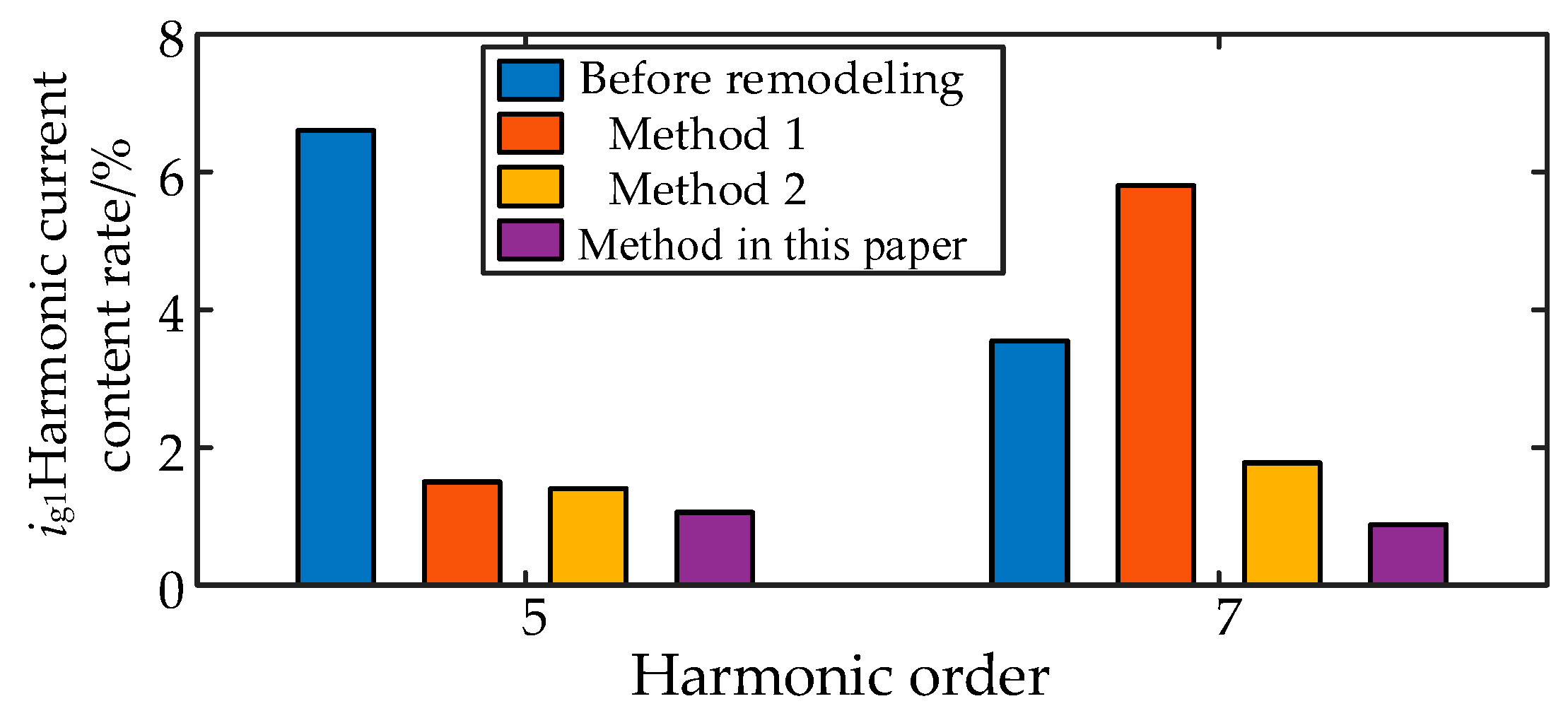
According to the previous analysis, although Method 2 can better offset the positive feedback path influence of the background harmonics of the power grid, the phase margin is still lacking, which will be aggravated when the number of inverters increases. The proposed method improves the phase margin to meet the engineering requirements. From the perspective of harmonic suppression, the method in this paper also has the best suppression effect on the inverter by background harmonics in Figure 28.
Therefore, for the grid-connected system of multiple inverters with background harmonics on the grid side, the impedance remodeling method in this paper has a good resonance suppression effect.
6. Conclusions
In this paper, firstly, the low-frequency and high-frequency harmonic current models are established, and secondly, the resonant characteristics of the system are established and analyzed by modal analysis. Then, the impedance remodeling harmonic resonance method is proposed based on the combination of the improved WACC control and the PCC shunt virtual conductor. The reasonableness of the impedance remodeling method is verified by comparing it with other strategies:
- (1)
- The high-frequency characteristics of the inverter tend to be filtered by the LCL filter to very small values until they are negligible. The harmonics of the inverter are mainly distributed at low frequencies.
- (2)
- The decomposed conductance model is more suitable for the modal analysis method for system resonance characterization than the traditional Norton circuit model, which can better reflect the response characteristics between the inverter and the grid. The modal analysis method can reflect the resonance information of the multi-inverter system.
- (3)
- The impedance remodeling method proposed in this paper is more suitable for resonance suppression of multi-inverter grid-connected systems in background harmonic scenarios than other schemes, and it can further reduce the output harmonic currents while meeting the engineering requirements.
The proposed impedance reshaping method can suppress the resonance of the inverter grid-connected current under weak grid conditions and greatly reduce its impact on the power quality of the inverter output current in the situation of rich background harmonics on the grid side. However, the control strategy of its impedance reshaping method needs to be matched with the control strategy of the actual inverter, and its control is complex. Secondly, in the grid structure where distributed power sources are connected to the grid, nonlinear loads also affect the incoming current harmonics of the system. In addition to the research on harmonic cooperative compensation capabilities, the next step should be considered.
Author Contributions
Conceptualization, M.Z., L.C. and Y.X.; methodology, M.Z. and J.W.; software, S.Z. and L.G.; validation, M.Z., J.W. and L.C.; formal analysis, L.C. and Y.X.; investigation, M.Z. and Y.X.; resources, J.W. and S.Z.; data curation, L.G. and X.G.; writing—original draft preparation, M.Z. and J.W.; writing—review and editing, L.C. and Y.X. All authors have read and agreed to the published version of the manuscript.
Funding
This research was funded by the State Grid Shanxi Electric Power Company Science and Technology Project Research (Research on the Key Technology of Modeling and Control of Generalized Power Impact Load Operation Characteristics Under Background of New Power Systems (52053022000A)).
Institutional Review Board Statement
Not applicable.
Informed Consent Statement
Not applicable.
Data Availability Statement
Not applicable.
Acknowledgments
We appreciate our reviewers and editors for their precious time.
Conflicts of Interest
The authors declare no conflict of interest.
References
- Du, E.; Zhang, N.; Hodge, B.; Wang, Q.; Kang, C.; Kroposk, B.; Xia, Q. The role of concentrating solar power toward high renewable energy penetrated power systems. IEEE Trans. Power Syst. 2018, 33, 6630–6641. [Google Scholar] [CrossRef]
- Hosseinzadeh, N.; Aziz, A.; Mahmud, A.; Gargoom, A.; Rabbani, M. Voltage stability of power systems with renewable-energy inverter-based generators: A review. Electronics 2021, 10, 115. [Google Scholar] [CrossRef]
- Joan, R.; Alvaro, L.; Frede, B. Control of power converters in AC microgrids. IEEE Trans. Power Electron. 2012, 27, 4734–4749. [Google Scholar]
- Yu, J.; Lin, X.; Song, D.; Yu, R.; Li, Y.; Mei, S. Harmonic instability and amplification for grid-connected inverter with voltage harmonics compensation considering phase-locked loop. IEEE J. Emerg. Sel. Top. Power Electron. 2020, 8, 3944–3959. [Google Scholar] [CrossRef]
- Zhong, P.; Sun, J.; Zhen, T.; Huang, M.; Yu, P.; Zha, X. An improved impedance measurement method for grid-connected inverter systems considering the background harmonics and frequency deviation. IEEE J. Emerg. Sel. Top. Power Electron. 2021, 9, 4236–4247. [Google Scholar] [CrossRef]
- Wang, F.; Duarte, J.L.; Hendrix, M.A.M.; Ribeiro, P.F. Modeling and analysis of grid harmonic distortion impact of aggregated DG inverters. IEEE Trans. Power Electron. 2011, 26, 786–797. [Google Scholar] [CrossRef]
- Liu, Q.; Liu, F.; Zou, R.; Li, Y. Harmonic resonance characteristic of large-scale PV plant: Modelling, analysis, and engineering case. IEEE Trans. Power Deliv. 2022, 37, 2359–2368. [Google Scholar] [CrossRef]
- Xu, R.; Zhang, C.; Xu, Y.; Dong, Z.; Zhang, R. Multi-objective hierarchically-coordinated volt/var control for active distribution networks with droop-controlled PV inverters. IEEE Trans. Smart Grid 2022, 13, 998–1011. [Google Scholar] [CrossRef]
- Batzelis, E.I.; Papathanassiou, S.A. A method for the analytical extraction of the single-diode PV model parameters. IEEE Trans. Sustain. Energy 2016, 7, 504–512. [Google Scholar] [CrossRef]
- Wang, H.; Huang, Q.; Li, Z.S. A dynamic bayesian network control strategy for modeling grid-connected inverter stability. IEEE Trans. Reliab. 2022, 71, 75–86. [Google Scholar] [CrossRef]
- Sun, J. Impedance-based stability criterion for grid-connected inverters. IEEE Trans. Power Electron. 2011, 26, 3075–3078. [Google Scholar] [CrossRef]
- Espin, F.G.; Figueres, E.; Garcera, G. An adaptive synchronous-reference-frame phase-locked loop for power quality improvement in a polluted utility grid. IEEE Trans. Power Electron. 2012, 59, 2718–2731. [Google Scholar]
- Mohammed, N.; Zhou, W.; Bahrani, B. Comparison of PLL-Based and PLL-Less Control Strategies for Grid-Following Inverters Considering Time and Frequency Domain Analysis. IEEE Access 2022, 10, 80518–80538. [Google Scholar] [CrossRef]
- Wang, X.; Blaabjerg, F.; Liserre, M. An active damper for stabilizing power-electronics-based AC systems. IEEE Trans. Power Electron. 2014, 29, 3318–3329. [Google Scholar] [CrossRef]
- Cao, W.; Ma, Y.; Wang, F. Sequence-impedance-based harmonic stability analysis and controller parameter design of three-phase inverter-based multibus AC power systems. IEEE Trans. Power Electron. 2017, 32, 7674–7693. [Google Scholar] [CrossRef]
- Wen, B.; Boroyevich, D.; Burgos, R. Inverse Nyquist stability criterion for grid-tied inverters. IEEE Trans. Power Electron. 2017, 32, 1548–1556. [Google Scholar] [CrossRef]
- Nie, C.; Lei, W.; Wang, Y.; Wang, H.; Feng, G. Resonance analysis of multi-paralleled converter systems and research on optimal virtual resistor damping methods. Proc. CSEE 2017, 37, 1467–1478. [Google Scholar]
- Chen, L.; Xu, Y.; Tao, S.; Wang, T.; Sun, S. Multi-inverter resonance modal analysis based on decomposed conductance model. Electronics 2023, 12, 1251. [Google Scholar] [CrossRef]
- Zou, C.; Liu, B.; Duan, S.; Li, R. Influence of delay on system stability and delay optimization of grid-connected inverters with LCL filter. IEEE Trans. Ind. Inf. 2014, 10, 1775–1784. [Google Scholar] [CrossRef]
- Wang, X.; Ruan, X.; Liu, S.; Tse, C.K. Full feedforward of grid voltage for grid-connected inverter with LCL filter to suppress current distortion due to grid voltage harmonics. IEEE Trans. Power Electron. 2010, 25, 3119–3127. [Google Scholar] [CrossRef]
- Sun, J.; Wang, Y.; Yang, Z. Improved WACC weighted coefficient method for LCL grid-connected inverter considering the influence of voltage feedforward. Proc. CSEE 2018, 38, 5158–5166. [Google Scholar]
- Xu, J.; Cao, X.; Hao, Z. A Harmonic-current suppression method for virtual synchronous rectifier based on feedforward of grid harmonic voltage. Tran. China Electrotech. Soc. 2022, 37, 2018–2029. [Google Scholar]
- He, N.; Xu, D.; Zhu, Y.; Zhang, J.; Shen, G.; Zhang, Y.; Ma, J.; Liu, C. Weighted average current control in a three-phase grid inverter with an LCL filter. IEEE Trans. Power Electron. 2013, 28, 2785–2797. [Google Scholar] [CrossRef]
- Xu, J.; Xie, S.; Huang, R. A Robust current control strategy for grid-connected inverters with LCL filtered. Autom. Electr. Power Syst. 2012, 36, 99–104. [Google Scholar]
- Bonaldo, J.P.; Tofoli, F.L.; Monteiro, R.V.A.; Morales-Paredes, H.K. Comparative analysis of techniques for the limitation of compensation currents in multifunctional grid-tied inverters. Int. J. Electr. Power Energy Syst. 2021, 126, 106574. [Google Scholar] [CrossRef]
- Chilipi, R.; Sumaiti, A.A.; Singh, B. Control of Grid-Tied Multiple Distributed Generation Systems with Cooperative Compensation Capabilities. IEEE J. Emerg. Sel. Top. Ind. Electron. 2022, 3, 821–833. [Google Scholar] [CrossRef]
- Herbert, L.G.; Czarnecki, L.S. An Optimization based method for selection of resonant harmonic filter branch parameters. IEEE Trans. Power Deliv. 2006, 21, 1445–1451. [Google Scholar]
- Yang, T.D.; Ruan, X.; Wu, H. Impedance shaping of the grid-connected inverter with LCL filter to improve its adaptability to the weak grid condition. IEEE Trans. Power Electron. 2014, 29, 5795–5805. [Google Scholar] [CrossRef]
- Wang, Y.; Gao, A.; Hu, N. Resonance suppression strategy for multi-parallel grid-connected inverters. South. Power Syst. Technol. 2022, 16, 87–96. [Google Scholar]
- Li, S.; Lin, H. Passivity enhancement-based general design of capacitor current active damping for LCL-type grid-tied inverter. IEEE Trans. Power Electron. 2023, 38, 8223–8236. [Google Scholar] [CrossRef]
- Wang, X.; Wang, S.; Wang, S.; Yang, C.; Zhao, X. A Digital Delay Compensation Method to Improve the Stability of LCL Grid-Connected Inverters. Energies 2021, 14, 2730. [Google Scholar] [CrossRef]
- Domenico, S.; Silas, A.S.; Tofolib, F.L.; Leãoa, R.P.S.; Sombraa, A.K.R. An integrated design approach of LCL filters based on nonlinear inductors for grid-connected inverter applications. Electr. Power Syst. Res. 2020, 186, 106389. [Google Scholar]
Figure 1.
Structure diagram of the LCL inverter.

Figure 2.
Mathematical model of capacitive current feedback active damping control method.
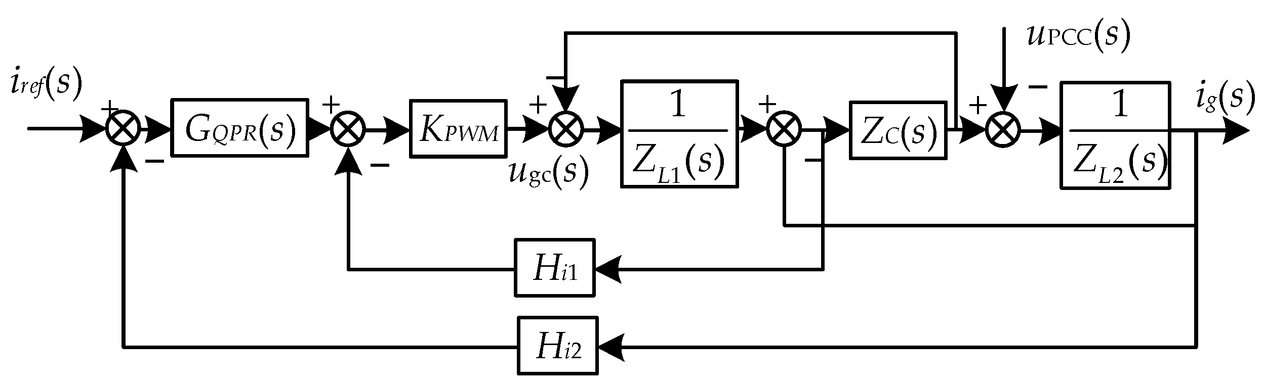
Figure 3.
Model of the grid-connected inverter for the low-frequency harmonic.
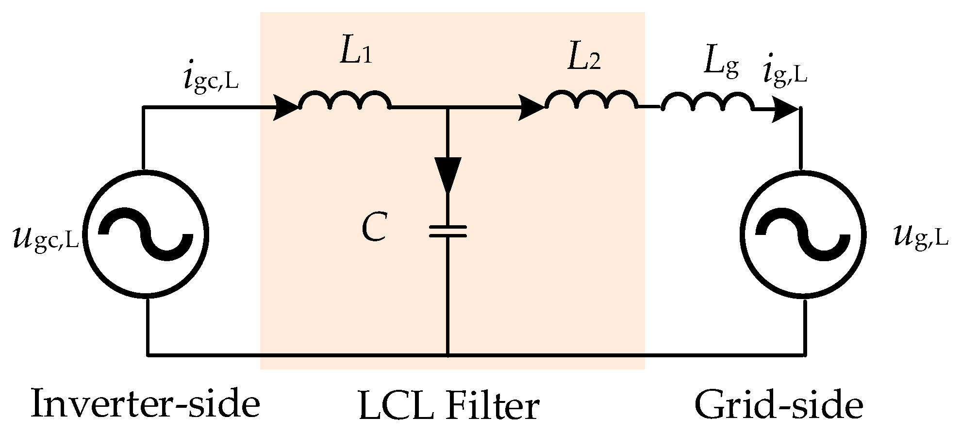
Figure 4.
Steady-state vector relationship.

Figure 5.
Model of the grid-connected inverter for the high-frequency harmonic.

Figure 6.
Harmonic current modeling and simulation verification: (a) low frequency; (b) high frequency.
Figure 6.
Harmonic current modeling and simulation verification: (a) low frequency; (b) high frequency.
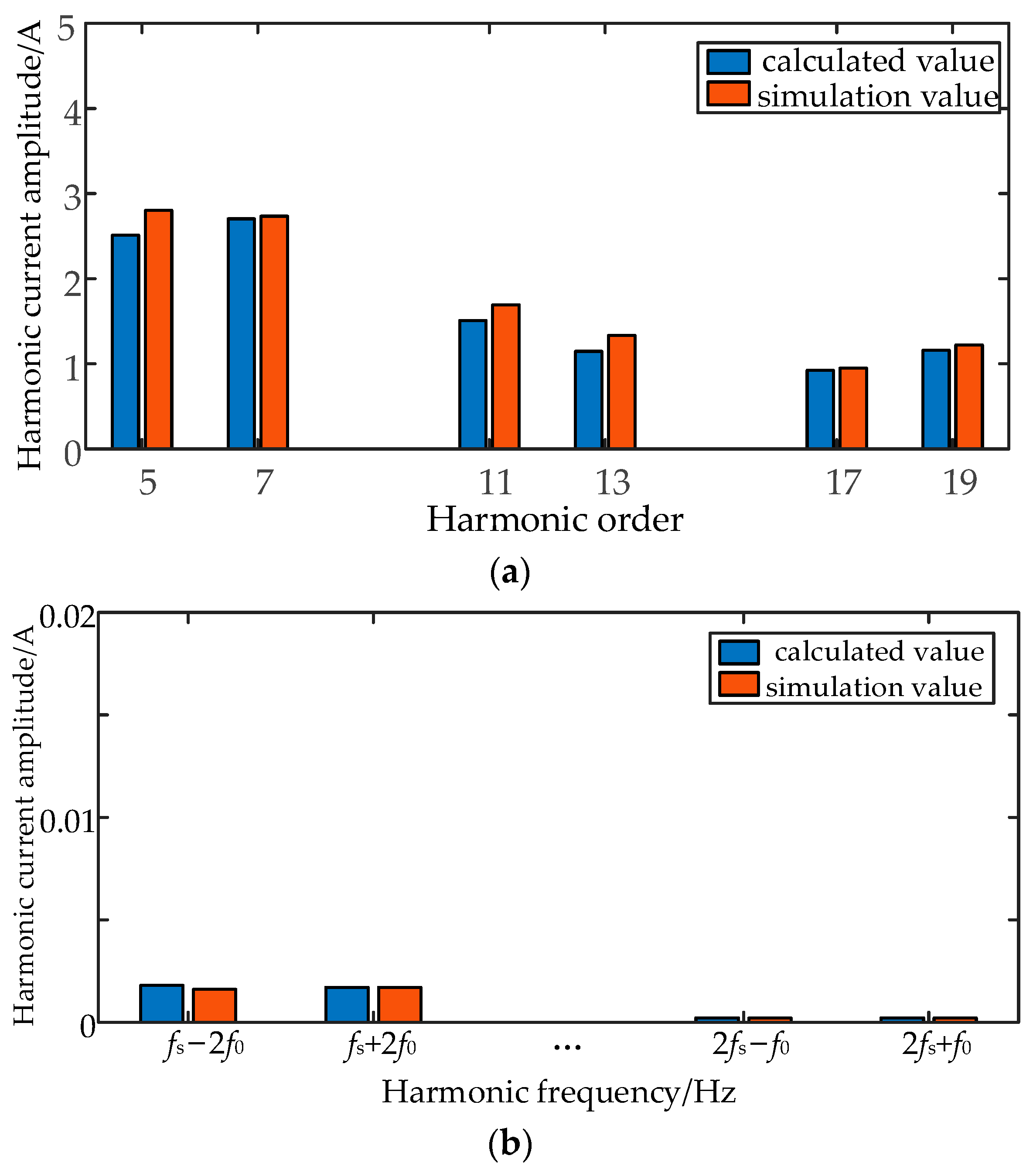
Figure 7.
Characterization of the low-frequency harmonic properties: (a) L1; (b) L2; (c) C; (d) Lg; (e) Kp; (f) Hi1.
Figure 7.
Characterization of the low-frequency harmonic properties: (a) L1; (b) L2; (c) C; (d) Lg; (e) Kp; (f) Hi1.

Figure 8.
Control with grid voltage feed-forward link.

Figure 9.
Comparison of harmonic current amplitude with and without feed-forward link.
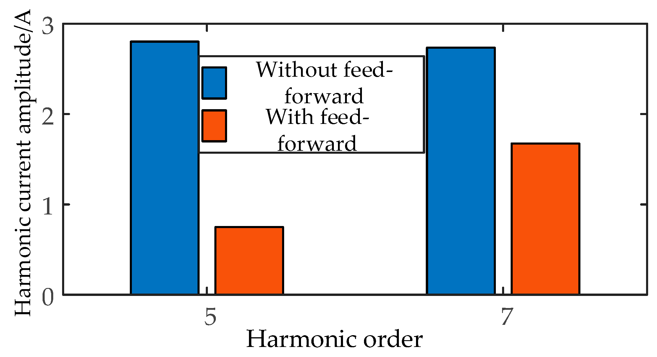
Figure 10.
Equivalent transformation of Figure 8.
Figure 10.
Equivalent transformation of Figure 8.
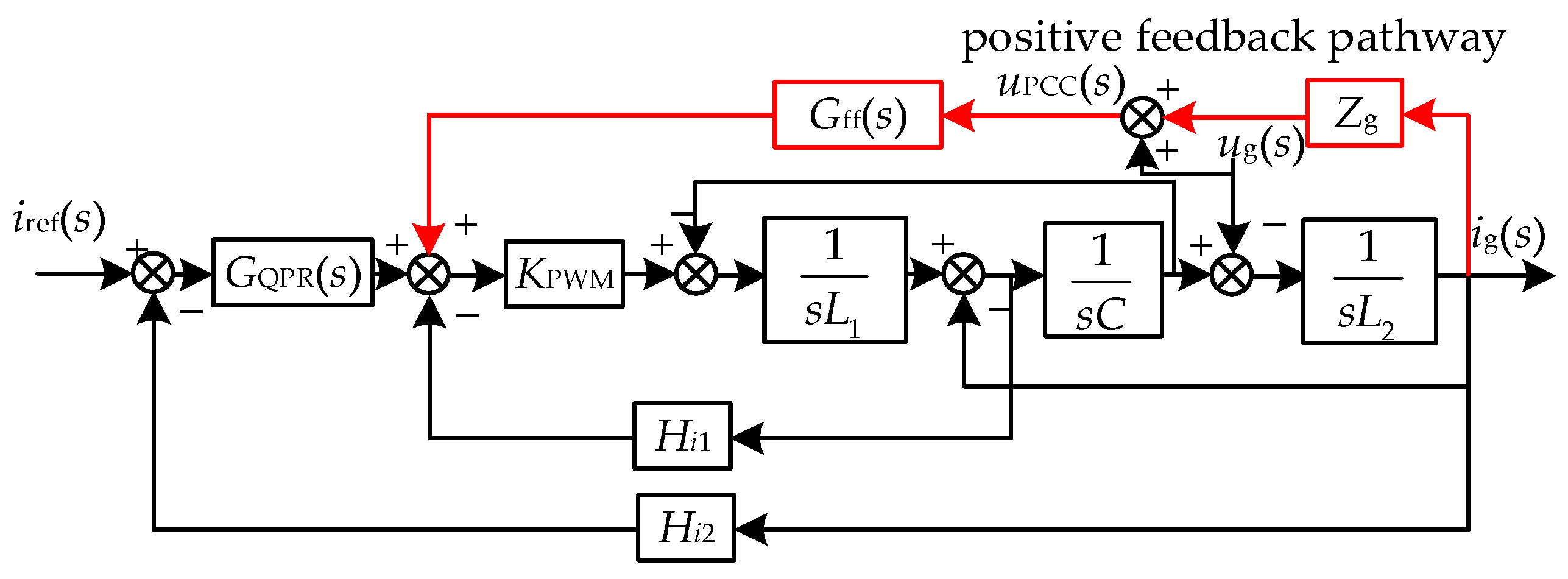
Figure 11.
Amplitude and frequency characteristics curve of the inverter output conductance and grid conductance.
Figure 11.
Amplitude and frequency characteristics curve of the inverter output conductance and grid conductance.
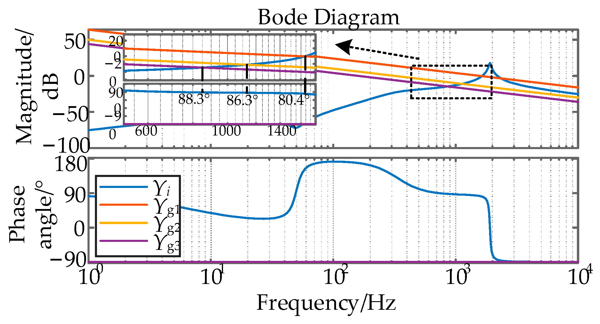
Figure 12.
Three-decomposition conduction model: (a) Control block diagram of the triple decomposition conductivity; (b) equivalent model under the triple decomposition conductivity.
Figure 12.
Three-decomposition conduction model: (a) Control block diagram of the triple decomposition conductivity; (b) equivalent model under the triple decomposition conductivity.

Figure 13.
Equivalent model of the multi-inverter grid-connected system.

Figure 14.
The specific process of the resonant mode analysis.

Figure 15.
The modal impedance curve when n is changed: (a) n = 1; (b) n = 2; (c) n = 3; (d) n = 4.

Figure 16.
Improved WACC current control method.
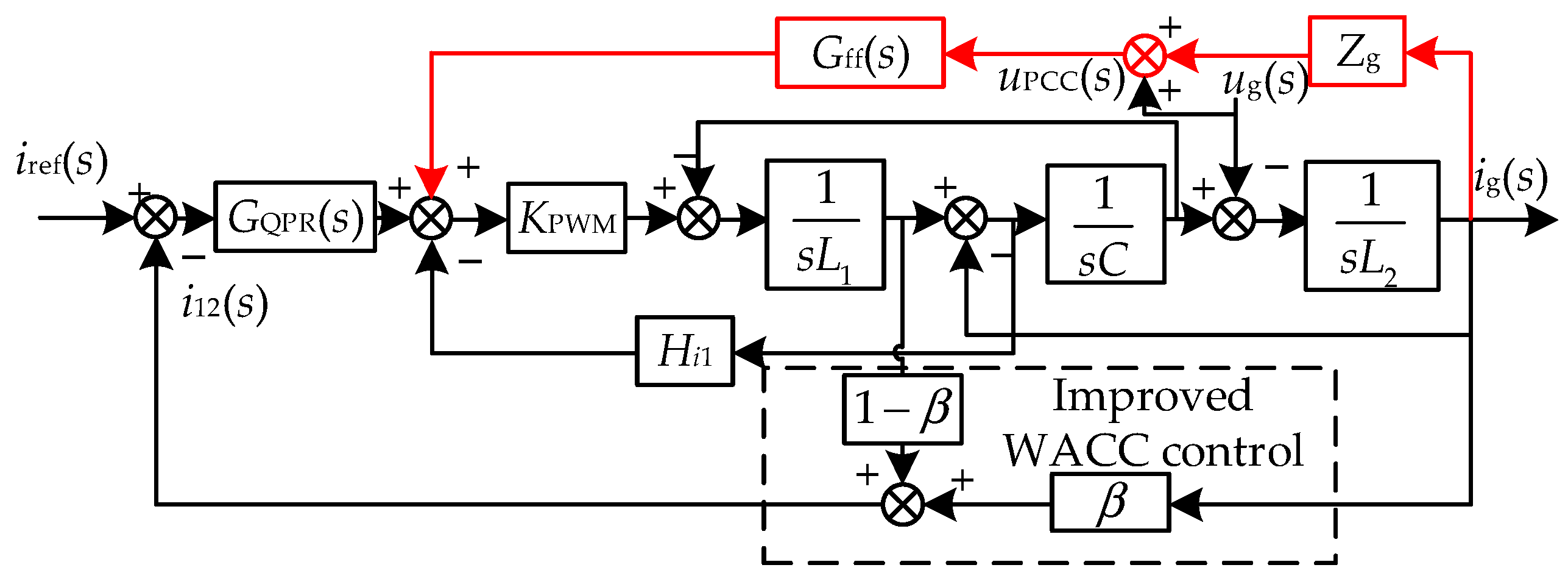
Figure 17.
Amplitude and frequency characteristic curves of inverter output conductance and grid conductance when Hi3 varies: (a) Medium and high-frequency characteristics; (b) low-frequency characteristics.
Figure 17.
Amplitude and frequency characteristic curves of inverter output conductance and grid conductance when Hi3 varies: (a) Medium and high-frequency characteristics; (b) low-frequency characteristics.
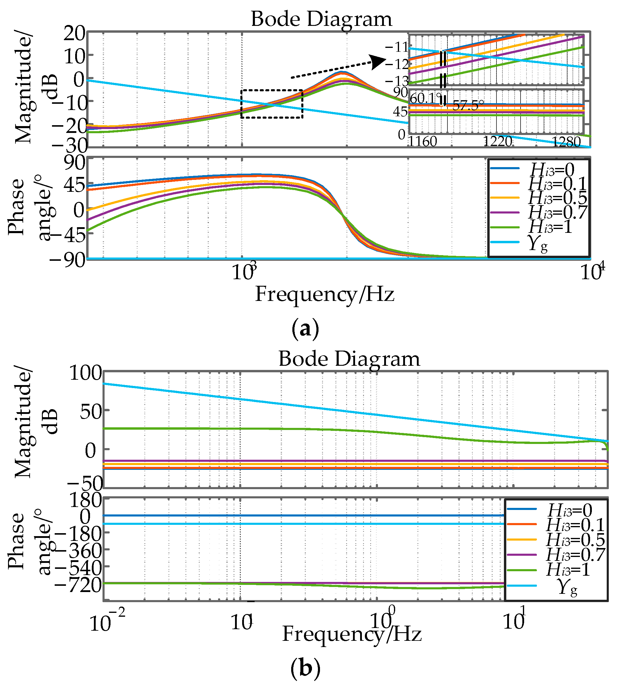
Figure 18.
Amplitude-frequency characteristic curves of the notch filter when Q varies.

Figure 19.
The impedance remodeling control method proposed in this paper.
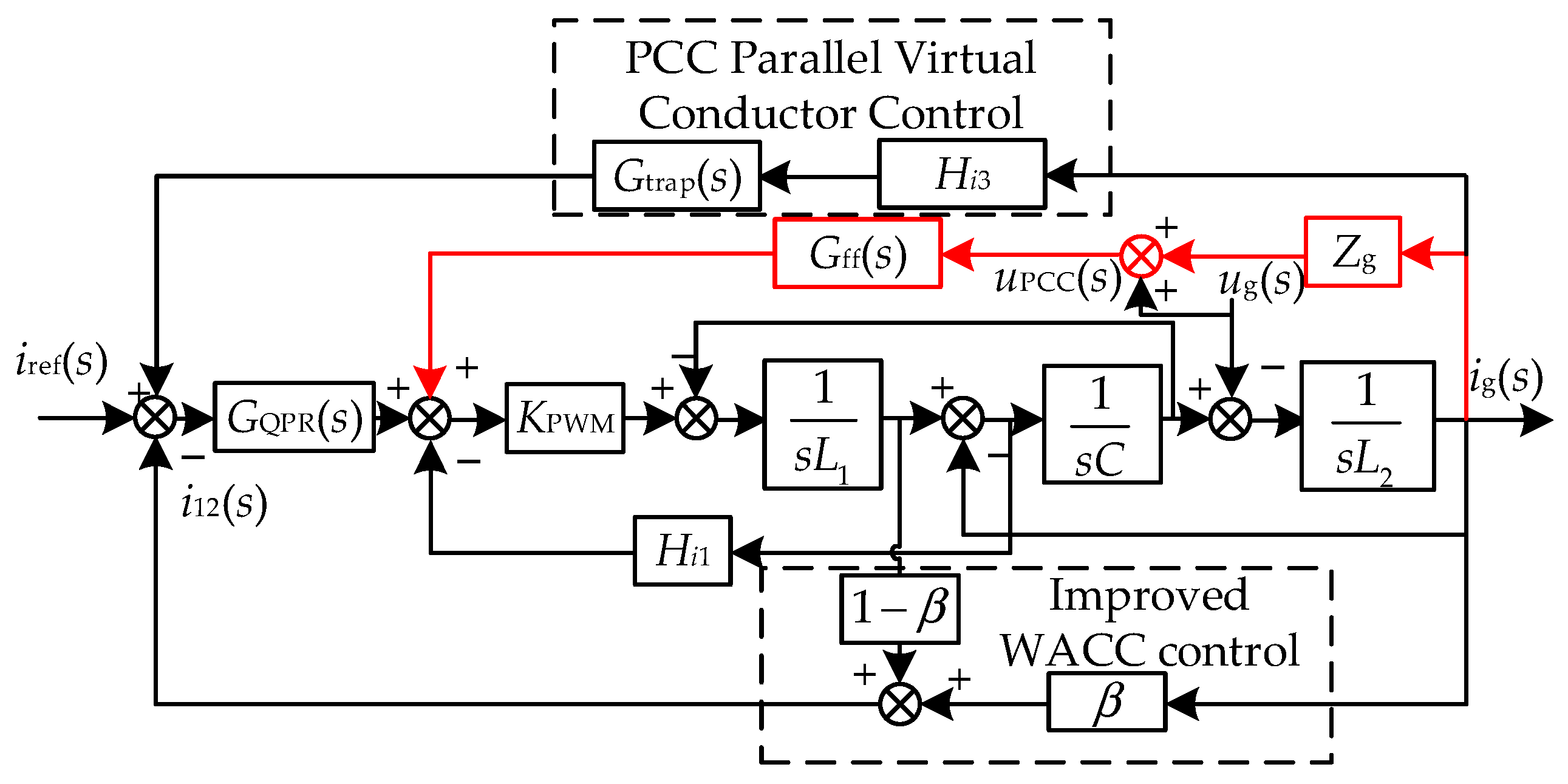
Figure 20.
Modal impedance curve when n changes after impedance remodeling: (a) n = 1; (b) n = 2; (c) n = 3; (d) n = 4.
Figure 20.
Modal impedance curve when n changes after impedance remodeling: (a) n = 1; (b) n = 2; (c) n = 3; (d) n = 4.
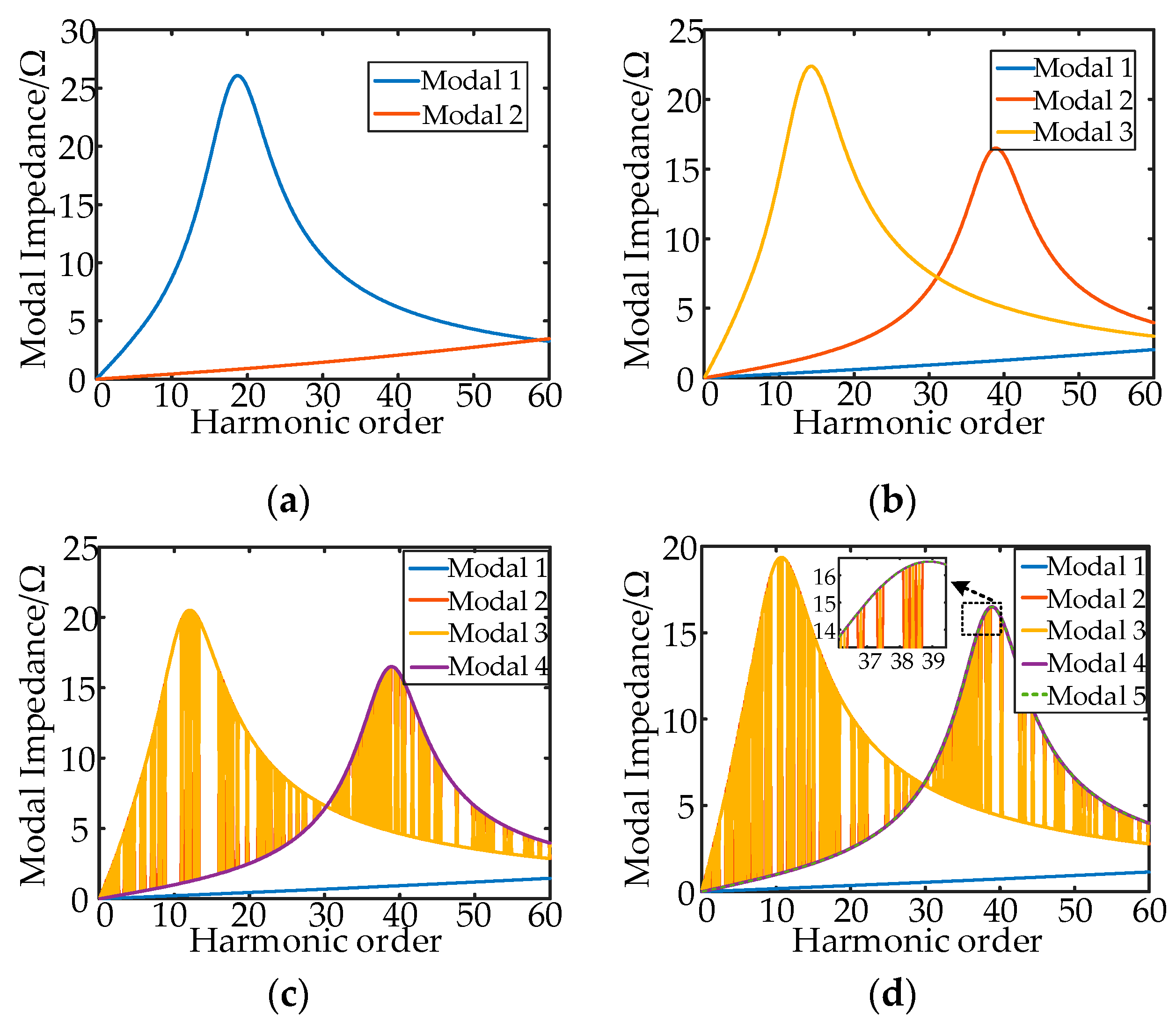
Figure 21.
Nyquist diagrams of the system for different values of Lg: (a) Before remodeling; (b) after remodeling.
Figure 21.
Nyquist diagrams of the system for different values of Lg: (a) Before remodeling; (b) after remodeling.
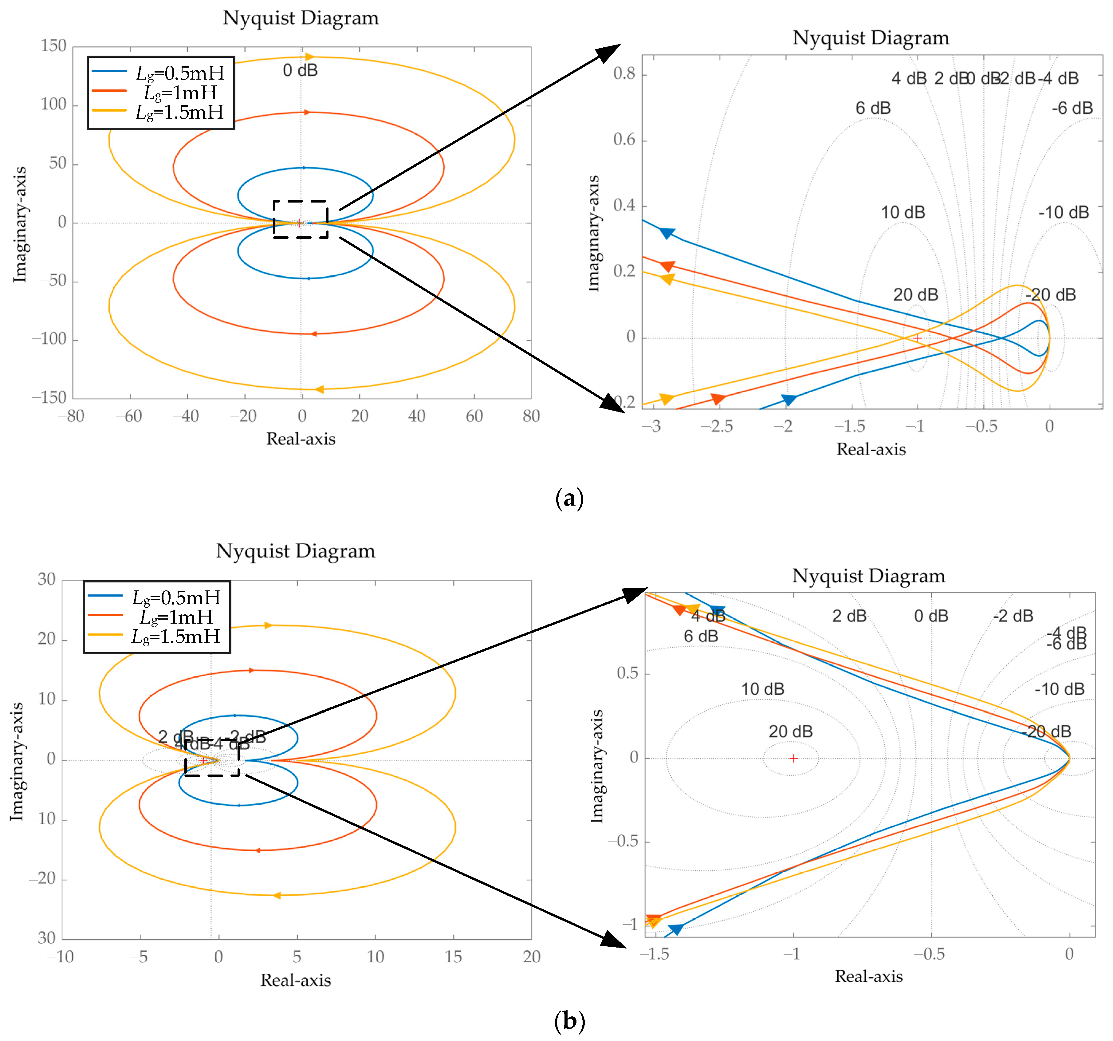
Figure 22.
Modal resonance characteristics when Lg varies: (a) Before remodeling; (b) Method 1; (c) Method 2; (d) Method in this paper.
Figure 22.
Modal resonance characteristics when Lg varies: (a) Before remodeling; (b) Method 1; (c) Method 2; (d) Method in this paper.
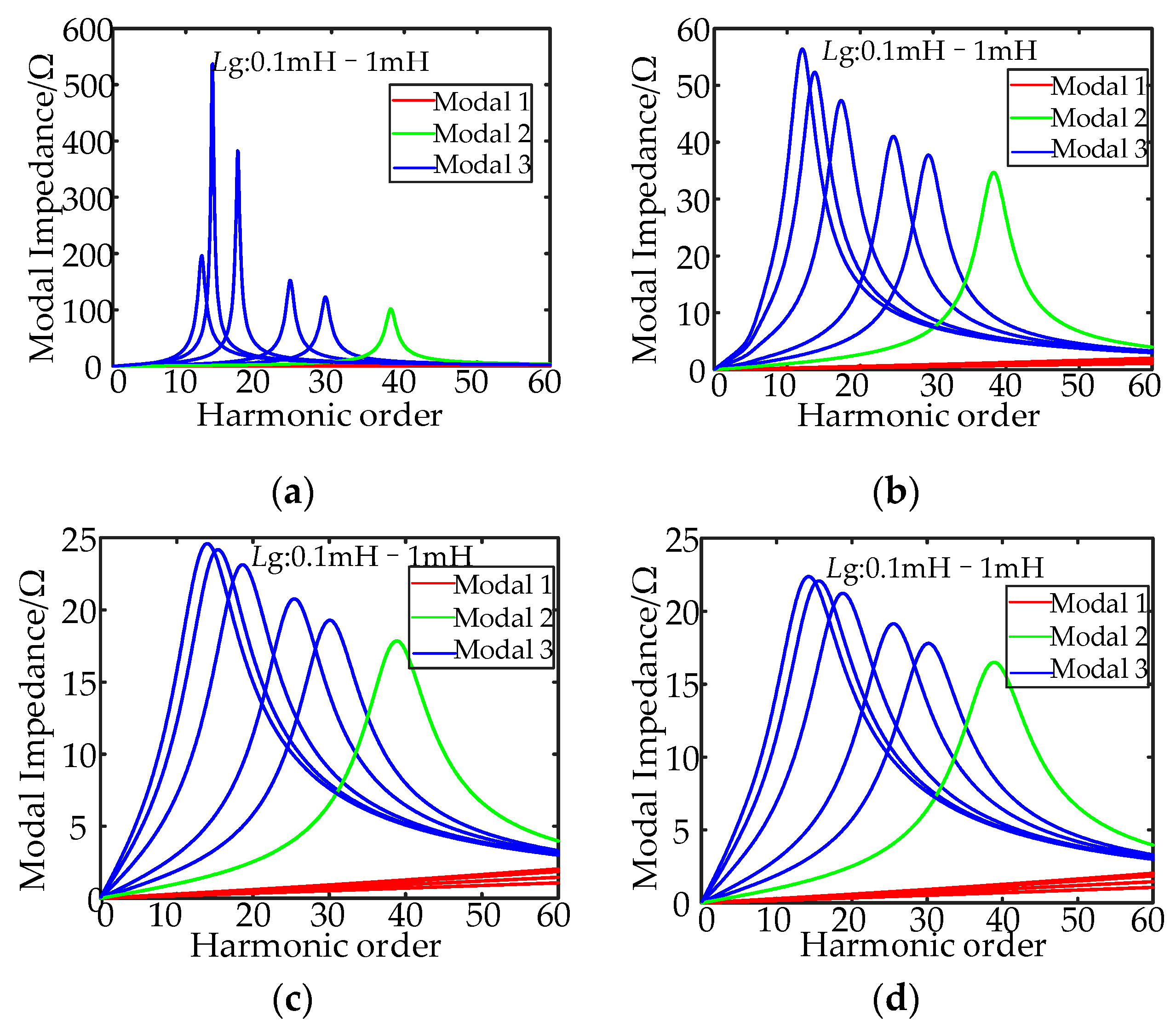
Figure 23.
Waveform of a single inverter at grid-connected conditions without background harmonics: (a) Lg = 0.1 mH; (b) Lg = 1 mH.
Figure 23.
Waveform of a single inverter at grid-connected conditions without background harmonics: (a) Lg = 0.1 mH; (b) Lg = 1 mH.

Figure 24.
FFT current spectrum results of a single inverter at grid-connected conditions without background harmonics: (a) Lg = 0.1 mH; (b) Lg = 1 mH.
Figure 24.
FFT current spectrum results of a single inverter at grid-connected conditions without background harmonics: (a) Lg = 0.1 mH; (b) Lg = 1 mH.
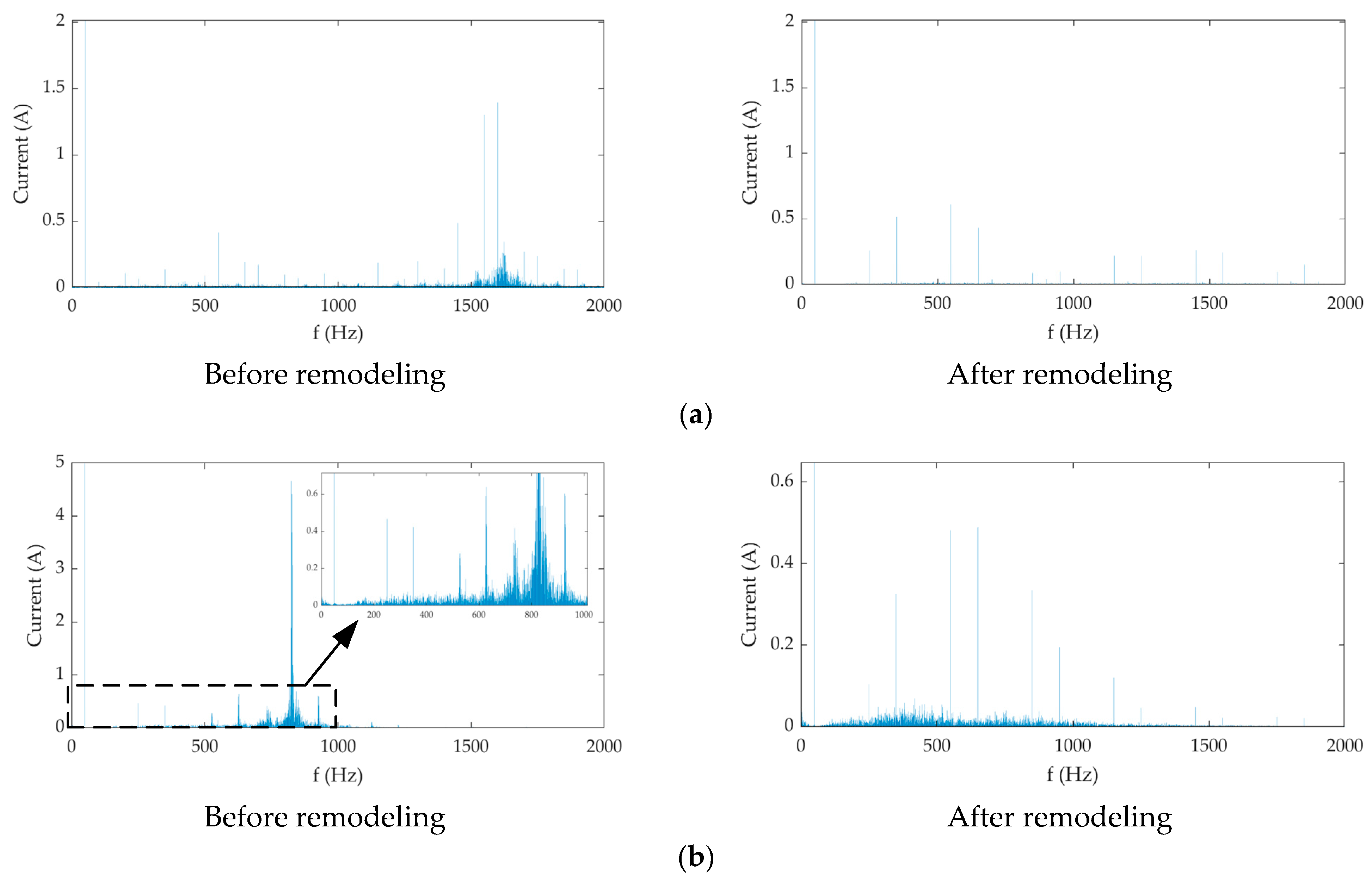
Figure 25.
Waveforms in the presence of background harmonics: (a) single unit operation; (b) two units operation.
Figure 25.
Waveforms in the presence of background harmonics: (a) single unit operation; (b) two units operation.

Figure 26.
FFT current spectrum results in the presence of background harmonics: (a) single unit operation; (b) two units operation.
Figure 26.
FFT current spectrum results in the presence of background harmonics: (a) single unit operation; (b) two units operation.

Figure 27.
Waveforms under different strategies at Lg = 1 mH with background harmonics: (a) single unit operation; (b) two unit operation.
Figure 27.
Waveforms under different strategies at Lg = 1 mH with background harmonics: (a) single unit operation; (b) two unit operation.

Figure 28.
Comparison of low-frequency harmonic current amplitudes for different suppression methods.
Figure 28.
Comparison of low-frequency harmonic current amplitudes for different suppression methods.

Table 1.
Comparison of harmonic resonance suppression methods.
| Methods | Realization | Advantages | Drawbacks |
|---|---|---|---|
| Passive damping method [22] | This is accomplished by connecting resistors in series or parallel to the inductive or capacitive branches of the LCL filter. | It is simple, easy to implement and effective | Energy losses due to passive damping resistors cannot be avoided. |
| Active damping method [29] | It is the virtualization of the damping resistor through the control algorithm that ensures the damping effect and avoids the energy consumption of the damping resistor. | A good suppression effect is achieved without additional energy loss. | The requirements for the inverter control circuit are very high. |
| Active damper method [30] | Active dampers are additional devices independent of the grid-connected inverter system. | It can be set independently without affecting the work of other inverters. | Research in resonance detection is not advanced enough to require additional construction and maintenance costs. |
| Impedance remodeling method [28] | Changing the system impedance destroys the resonance conditions of the system and thus acts as a resonance suppressor. | It will not add extra energy loss and can achieve a better suppression effect. | The algorithm is complex and demanding on the inverter control circuit. |
Table 2.
The parameters of the grid-connected inverter.
| Parameters | Symbol | Value |
|---|---|---|
| Power grid voltage | Ug/V | 220 |
| Power grid impedance | Lg/mH | 0.1 |
| Inverter side inductor | L1/mH | 1.2 |
| Grid-side inductance | L2/mH | 0.3 |
| Filter capacitor | C/μF | 28 |
| Quasi-proportional resonance controller parameters | kp | 3 |
| ki | 100 | |
| ωi/rad·s−1 | 5 | |
| Capacitive current feedback coefficient | Hi1 | 3 |
| Grid-connected current feedback coefficient | Hi2 | 1 |
Disclaimer/Publisher’s Note: The statements, opinions and data contained in all publications are solely those of the individual author(s) and contributor(s) and not of MDPI and/or the editor(s). MDPI and/or the editor(s) disclaim responsibility for any injury to people or property resulting from any ideas, methods, instructions or products referred to in the content. |
© 2023 by the authors. Licensee MDPI, Basel, Switzerland. This article is an open access article distributed under the terms and conditions of the Creative Commons Attribution (CC BY) license (https://creativecommons.org/licenses/by/4.0/).
Share and Cite
MDPI and ACS Style
Zhang, M.; Wang, J.; Zhang, S.; Gao, L.; Guo, X.; Chen, L.; Xu, Y. Harmonic Resonance Analysis and Impedance Remodeling Method of Multi-Inverter Grid-Connected System. Electronics 2023, 12, 3684. https://doi.org/10.3390/electronics12173684
AMA Style
Zhang M, Wang J, Zhang S, Gao L, Guo X, Chen L, Xu Y. Harmonic Resonance Analysis and Impedance Remodeling Method of Multi-Inverter Grid-Connected System. Electronics. 2023; 12(17):3684. https://doi.org/10.3390/electronics12173684
Chicago/Turabian StyleZhang, Min, Jinhao Wang, Shifeng Zhang, Le Gao, Xiangyu Guo, Lin Chen, and Yonghai Xu. 2023. "Harmonic Resonance Analysis and Impedance Remodeling Method of Multi-Inverter Grid-Connected System" Electronics 12, no. 17: 3684. https://doi.org/10.3390/electronics12173684
Note that from the first issue of 2016, this journal uses article numbers instead of page numbers. See further details here.