Abstract
This paper presents a versatile, low-cost real-time control platform with embedded isolated inputs and outputs for direct usage in electrical applications. The inputs correspond to voltage and current measurements, while the outputs are digital signals with isolated power supply. The validation for the platform considers the implementation of the power electronics topologies where the control algorithms are implemented in Simulink. The topologies are the interleaved three-phase buck converter, push–pull converter, H-bridge, and thyristor-based AC load controller. The control for them involves voltage feedback, current feedback, linear control algorithms, and the implementation of a discrete PLL algorithm for the last topology. Hence, the platform demonstrates the effectiveness of performing real-time control for some power electronics topologies.
1. Introduction
The application of control theory is a common field in several engineering areas, where the principal objective is to achieve the desired behavior in the output signals for a plant by manipulating the input signals. The development of control algorithms involves initial theoretical studies where common numerical computational simulation tools provide insights about the algorithm’s effectiveness in controlling the plant. Among these tools is MATLAB [1], Scilab [2], and Octave [3], among others. Later, the validation for the algorithms requires its experimental implementation into physical systems with the ability to act on the plant.
The real-time control algorithms implementation involves principally two options for the digital systems and real-time control platforms (RTCP). Digital systems allow the implementation of control algorithms with high performance. Between them are microcontrollers, digital signal processors (DSP), complex programmable logic devices (CPLD), and field-programmable gate arrays (FPGA), allowing the realization of discrete control algorithms at a reasonable cost. Instead, this option requires advanced low-level programming or hardware description language skills, like assembler, C/C++, and VHDL. It needs knowledge of analog and digital electronics to use these technologies adequately. Hence, using this option presents some challenges for realizing control algorithms for people without specialized programming/electronics knowledge.
On the other hand, the RTCP is defined under the Rapid Control Prototyping (RCP) 3550 protocol. These tools allow easy and direct implementation of the control algorithms by using high-level programming languages where commonly there are graphical interfaces [4]. Most of the RTCP allows its usage with MATLAB/Simulink due to the wide acceptance of this software in the academy and research. Additionally, the RTCP solutions have interfaces that help the integration of the control algorithms into real systems like digital input–outputs, analog data acquisition systems, analog outputs, digital protocols (SPI, UART, I2C), and others. Some RTCP commercial solutions are dSPACE [5], Typhoon [6], Plexim [7], Imperix [8], OPAL-RT, and RTDS, among others. Despite the advantages of these solutions, they have higher costs involving hardware and software licenses limiting access for users without adequate financial support.
In need of affordable RTCP, some proposals have been developed for engineering fields. Husain et al. [9] propose an RTC for the bioreactor control based on the Arduino platform and a GUI using Labview. Adam et al. [10] presents a platform for the control in a water pump based on the BeagleBone target and Linux, resulting in an open-source platform requiring low-level programming skills instead. Also, generic RTCPs have been developed. Krauss [11] presents an RTCP based on Arduino and UART communication with the PC. The control algorithms are written in C language. Zhong et al. [12] show a solution based on MATLAB/Simulink with a data acquisition board allowing the easy usage of Simulink, but it requires a PC to run the algorithms. Vargas-Salgado et al. [13] propose an open-source RTCP based on a PC using Linux and Scilab.
Other RTCP proposals consider advanced microcontrollers as the platform core, where a well-known family is the C2000 from Texas Instruments, which is well-suited for real-time control applications [14]. These devices can be programmed in C/C++ by Code Composer Studio [15] and in Simulink by the Embedded Coder Support Package for TI C2000 Processors [16]. The last one allows programming the devices by a graphical interface, avoiding using low-level language to implement the control algorithm. Chen et al. [17] propose an RTCP based on the device TMS320F2812 to work on mechatronics systems. It considers Simulink to program the platform. Quintero-Manriquez et al. [18] use an RTCP for implementing optimal control algorithms in induction motors and using Simulink. Prasannakumar and Nagamani [19] present a motor control platform using the Launchpad MCU development board LAUNCHXL-F28027 for a modularized solution. Aravena et al. [20] introduces an RTCP for power electronics applications based on the TMS320F28379D into the development board LAUNCHXL-F28379D, which can be programmed in C by Code Composer Studio and by Simulink. This option incorporates optically isolated outputs. These solutions have the analog-to-digital MCU peripheral in common to include sensors; hence, they require instrumentation boards to adapt physical measurements into the control algorithms. Also, they work based on a specific MCU device, whose computational capabilities and memory can be more or less potent for the required solution.
Thus, this work proposes a low-cost RTCP for power electronics applications with embedded current and voltage sensors. This solution considers isolation for the electrical measurements and the digital outputs. Also, the proposal is based on the Launchpad C2000 development boards, allowing the platform to be used for various MCU, from entry processors to the most advanced.
2. Low-Cost Real-Time Control Platform
The proposal considers embedding the digital controller with the input and output signals into the same board to achieve an integrated platform that allows the rapid implementation of real-time control algorithms into physical systems that involves electrical signals. Figure 1 shows the scheme for the platform, which presents isolated measurements for three voltage and three currents, five isolated two-channel digital outputs, and as the core for the platform, a microcontroller from the family C2000. The description for these elements is below.
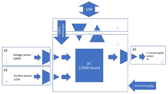
Figure 1.
General scheme for the real-time control platform system.
2.1. Isolated Sensor
The electrical sensors are based on resistive elements to obtain a reduced voltage for the voltage and current measurements. The voltage sensor considers exploiting a resistor divider. In contrast, the current sensor uses a shunt resistor, which aims to map the input voltage and current signals to low voltage measures in the range of ±250 mV for posterior signal processing. The voltage and current sensors allowed measurements of ±300 V and ±15 A, respectively. The isolated sensors implement an optical barrier isolation amplifier to generate a differential output voltage based on the input voltage measurement. The low-voltage measurement is moved to the control system by an optically based isolation amplifier, which takes the differential input from the sensors and generates a differential output voltage by applying a fixed gain. The use of differential signals reduces the common mode noise in the measurements. The circuit requires an adequately isolated and regulated power supply; hence, a DC-DC isolated converter is used with a voltage regulator. The circuits for the voltage and current sensors are shown in Figure 2.
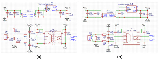
Figure 2.
Isolated electrical sensor for (a) voltage and (b) current measurements.
The microcontrollers for this platform use 12-bit single-ended analog-to-digital converters (ADC); hence, the differential output for the isolation amplifier needs conditioning. Figure 3 shows an operational amplifier circuit that creates a single signal with an offset voltage corresponding to half of the voltage reference for the ADC conversion (1.65 V).
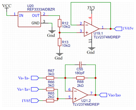
Figure 3.
Conditioning circuit for the microcontroller ADC.
Each circuit of the isolated voltage and current sensors uses the conditioning circuit to supply the respective signals to the ADC inputs of the microcontroller.
Figure 4 presents the current sensor response for a DC and AC sweep.
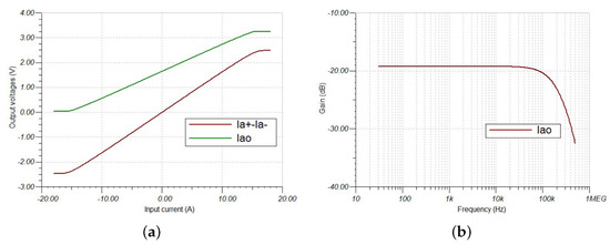
Figure 4.
Response for the current sensor (a) DC sweep (green output for conditioning circuit, violet output for differential amplifier) and (b) AC sweep (violet output for conditioning circuit).
The DC sweep evaluates the output for a DC input current from −18 A to 18 A, where a linear behavior is achieved in the range from −15 A to 15 A, with saturation outside of this. The AC sweep shows the bandwidth for the sensor, which is 130 kHz. The same study is carried out for the voltage sensor in Figure 5.
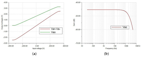
Figure 5.
Response for the voltage sensors (a) DC sweep (green output for conditioning circuit, violet output for differential amplifier) and (b) AC sweep (violet output for conditioning circuit).
The DC sweep considers a DC input voltage from −350 V to 350 V to obtain the output voltage, which presents a linear response in the range from −300 V to 300 V. The bandwidth is the same for the current sensor due to the same conditioning elements.
2.2. Isolated Digital Output
The outputs for the platform are isolated digital electrical signals with its power supply. The outputs implement two-channel semiconductor-based isolation barrier digital isolators. These devices need a floating power supply to work on the secondary side to achieve adequate isolation; hence, the isolated output supply implements single-chip isolated DC-DC converters, the same for the measurement stage. The circuit proposed to obtain the single digital output is presented in Figure 6. Thus, each one of the five platform outputs has two channels with its floating power supply. The digital outputs for each channel work on 0 and 5 V levels for the logical values of 0 and 1, respectively. The digital output signal is also delayed 400 ns from the microcontroller pin output due to the digital isolator.
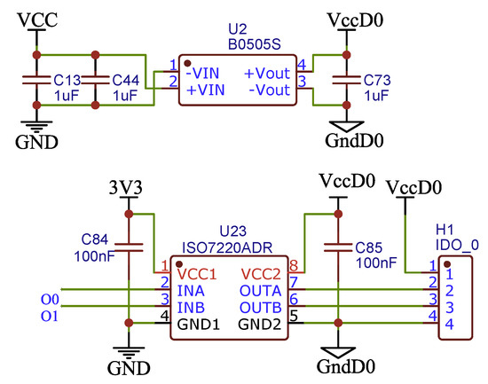
Figure 6.
Differential to a single analog signal converter.
2.3. Microcontroller Unit
The proposal considers microcontrollers from the C2000 family, which presents several advantages for implementing real-time control algorithms. The architecture of these devices is specially designed to integrate the elements of the closed-loop control system, which requires detecting signals from the analog domain, processing information by math engines, and updating the outputs. Adequately integrating these elements allows the control loop operation with low latency, achieving high performance [21,22]. This family has many devices with different computational capabilities and peripherals, allowing the users to select the microcontroller that best suits the solution without unnecessarily oversizing, leading to over costs [23]. Additionally, the manufacturer provides low-cost development boards called LAUNCHPAD to facilitate access to the microcontrollers without requiring the development of electronic circuits to test the devices. The LAUNCHPAD presents the same pinout for the peripherals, even for different microcontrollers, allowing the same functionality.
In this way, the platform design uses the LAUNCHPAD to achieve a versatile use for the digital processing device. Hence, some of them with different microcontrollers can fit into the platform without limiting it to only one microcontroller device. Initially, the platform considers the LAUNCHXL-F28027F (See Figure 7a) and the LAUNCHXL-F280049C (See Figure 7b), although other boards can be used. The first one costs USD 30 and runs at 60 MHz, while the second has a fee of USD 39 and runs at 100 MHz, including a floating-point unit (FPU) and a trigonometry-math unit (TMU).
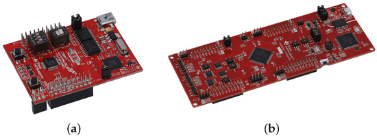
Figure 7.
Microcontroller boards based on the chips (a) TMS320F280049C and (b) TMS320F28027.
3. Real-Time Control Platform Prototype
The board for the real-time control platform is in Figure 8, where on the left are the voltage and current sensors, while at the right are the digital output signals.
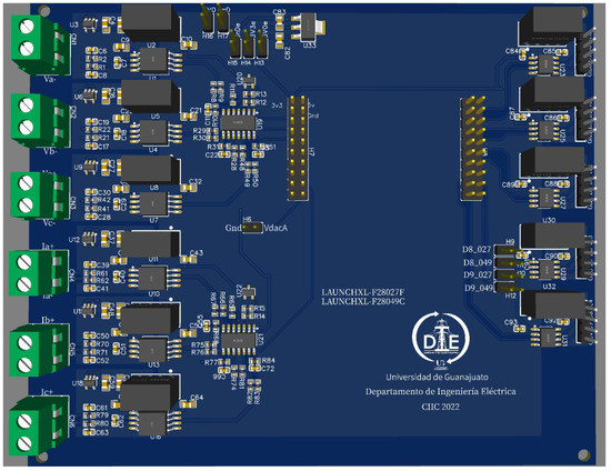
Figure 8.
Real-time control platform setup.
Also, it presents the connectors for the LAUNCHPAD, where pinout has the same peripheral functions for the different boards. The connections for the platform signals and microcontroller pins are in Figure 9a for LAUNCHXL-F28027F and Figure 9b for the board LAUNCHXL-F280049C.
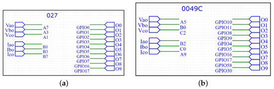
Figure 9.
Platform connections for the boards (a) LAUNCHXL-F28027F and (b) LAUNCHXL-F280049C.
The practical implementation for the real-time control platform is in Figure 10a, and the Platform with the LAUNCHPAD-F280049C is in Figure 10b. Hence, the platform can be used with different microcontrollers, requiring changing only the LAUNCHPAD to one, including the device of interest.
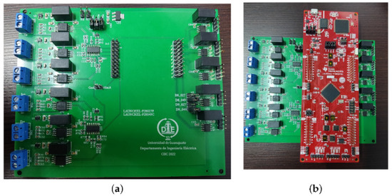
Figure 10.
Real-time control platform (a) board and (b) board-MCU.
4. Results
The platform’s validation considers the implementation of control algorithms to manage four power electronic topologies: the three-phase interleaved buck converter, push–pull converter, H-bridge, and thyristor-based AC load controller. The four topologies were selected to evaluate the capacity of the platform to implement solutions easily, involving isolated and non-isolated voltage feedback, current feedback, and a PLL algorithm for grid synchronization. So, the overall architecture was built without additional instrumentation for electrical signal measurement. The power electronic topologies use the LabVolt modules. The testing topologies use Power Electronics academic LabVolt modules. Additionally, the measurements are taken by the Oscilloscope Keysight DSOX2014A and the current probe Keysight 1146B.
The programming for the platform considers the use of Simulink and Code Composer Studio employing the MATLAB package Embedded Coder Support Package for TI C2000 Processors [16]. This option allows the generation and programming of the C/C++ code for the microcontroller directly from the Simulink models, moving quickly from the simulation to the practical implementation [24].
4.1. Test 1
This test considers the three-phase interleaved buck converter to obtain a reduced output voltage from the input voltage. This topology corresponds to a non-isolated DC-DC converter. Figure 11a,b show the circuit scheme and the experimental implementation for the topology, respectively.
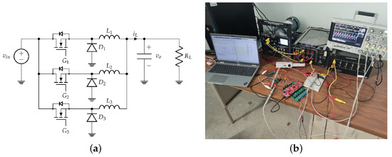
Figure 11.
Three-phase interleaved buck converter (a) scheme and (b) experimental setup.
The control involves managing the three power transistors , , by PWM, and the close-loop operation requires the output voltage measurement to implement the control law; thus, three digital outputs control the transistors, and one input voltage measures the output signal. The Simulink control implementation is shown in Figure 12, which considers the block diagram of a proportional integral (PI) controller described by
where the parameters and are the controller gains, which modify the dynamic response of the system.
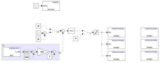
Figure 12.
Three-phase interleaved buck converter Simulink control model.
Once the control algorithms are on the platform, the experimental validation and controller parameter tuning can be performed. Figure 13 and Figure 14 present the output voltage responses while the set point changes between 20 V and 50 V for various controller parameters.
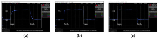
Figure 13.
Test 1 dynamic response for the controller parameters (a) , , (b) , , and (c) , .
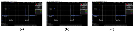
Figure 14.
Test 1 dynamic response for the controller parameters (a) , , (b) , , and (c) , .
Figure 13 presents the time domain responses while the parameter increases and = 0, while Figure 14 evaluates increasing for a fixed = 180. It can be observed in real-time how the dynamic response changes while the PI controller parameters change.
Figure 15 shows the output voltage dynamic responses for two controller parameter values while the load resistance changes between 240 to 120 .
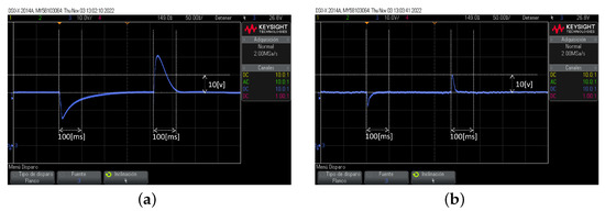
Figure 15.
Test 1 dynamic response for load variation with (a) , , and (b) , .
Finally, Figure 16 presents the signals , , for D = 30 and 15. Signal is not shown because only there are four oscilloscope probes.
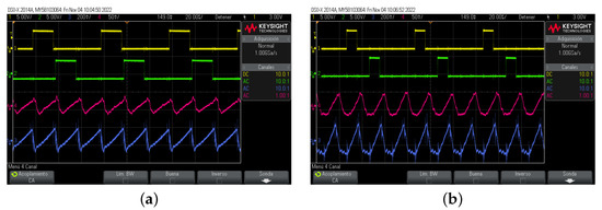
Figure 16.
Test 1 signals (yellow), (green), (pink), (blue) for (a) D = 30 and (b) D = 15.
4.2. Test 2
The second test considers the push–pull converter, an isolated DC-DC converter. Figure 17a,b present the scheme and experimental implementation for the topology, respectively.
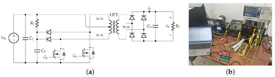
Figure 17.
Push–pull converter (a) schematic diagram and (b) experimental setup.
The control implies the feedback for the isolated voltage measurement and PWM managing for the transistors and by a proportional-integral control module. Figure 18 shows the Simulink implementation for the implemented control algorithms, including the PI control described by (1).
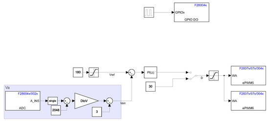
Figure 18.
Push–pull Simulink control model.
With the control algorithms on the platform, the validation considers the variation of the output voltage for some controller parameters. Figure 19 presents the dynamic response while the output voltage change between 180 V and 200 V for the proportional-integral parameters {, }, {, }, and {, }.
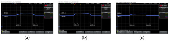
Figure 19.
Test 2 dynamic response for the controller parameters (a) , , (b) , , and (c) , .
It is noteworthy how the dynamic response change as the controller parameter does. Figure 20 shows the response for the output voltage while the load changes from 1200 to 600 ; this for the control parameters {, } and {, }. The output voltage presents a better response for load variation for the last set of control parameters.
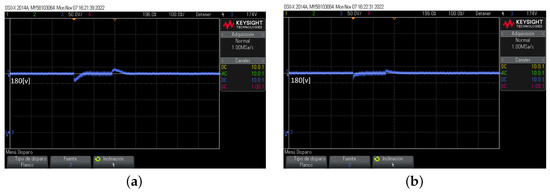
Figure 20.
Test 2 dynamic response for load variation with (a) , and (b) , .
Finally, the signals , , are in Figure 21 for D = 10 and 30. Hence, this test validates the use of the platform for this isolated power electronics topology.
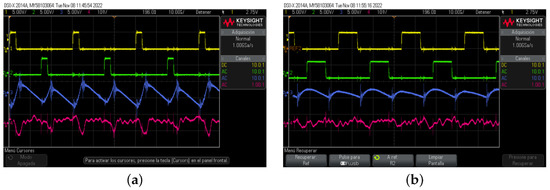
Figure 21.
Test 2 signals (yellow), (green), (blue), (pink) for (a) D = 10 and (b) D = 30.
4.3. Test 3
This test involves the use of an H-bridge power electronics topology to the current control of an AC load. Figure 22a,b show the schematic diagram and experimental setup, respectively.
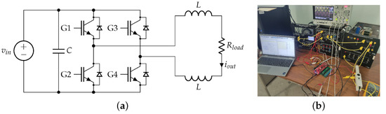
Figure 22.
H-bridge converter (a) schematic diagram and (b) experimental setup for voltage and current measurements.
The application requires the output current measurement and the PWM management for the transistors , , , and by a PI controller. The Simulink control implementation is in Figure 23.
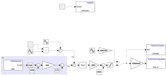
Figure 23.
Simulink description of the H-bridge driver.
Figure 24 shows the PWM duty cycle and the output current measurement for the implemented system. The DAC in the MCU generates the duty cycle analog signal to be viewed in the oscilloscope. Figure 24 presents the response in open- and closed-loop operations. Additionally, Figure 24a considers the duty cycle generation as an open loop by an ideal sine waveform where the output current corresponds to a distorted AC signal. For the closed-loop, Figure 24b involves using the PI controller to generate the PWM duty cycle resulting in a better waveform for the output current.
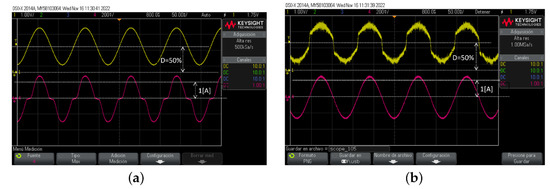
Figure 24.
Test 3 signals Dutty cycle (yellow), (pink) for (a) open loop and (b) closed loop.
Figure 25 shows the response for varying reference for the output current magnitude from 1 A to 2 A, where the resulting signal presents good behavior. Thus, the platform can incorporate current signals into the control algorithms.
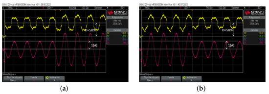
Figure 25.
Test 3 signals varying signals from (a) 1 A peak to 2 A peak and (b) 2 A peak to 1 A peak.
4.4. Test 4
The fourth test implements the control for the thyristor-based AC-load controller, involving the input voltage measurement, managing the thyristors and , and the realization of the phase-detection algorithm. Figure 26a,b show the scheme for the topology and the practical implementation for this case study.
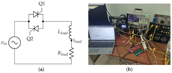
Figure 26.
Thyristor-based AC load controller (a) schematic diagram and (b) experimental setup.
The control for the thyristors requires the input voltage phase comparison with a reference angle . Figure 27a presents the Simulink control for this topology. The phase-detection implements a phase-locked loop (PLL) with DC offset rejection [25], which is implemented by the circuit shown in Figure 27b.
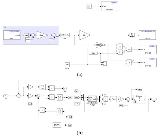
Figure 27.
Thyristor-based AC load controller algorithms (a) complete control scheme and (b) PLL.
Additionally, Figure 28 shows the signals , for the PLL, and , while the angle takes the values 0°, (b) 45°, (c) 90°, and (d) 135°, respectively.
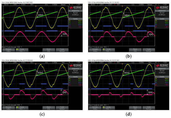
Figure 28.
Test 4 results presenting the output waveforms for the angle (a) 0°, (b) 45°, (c) 90°, and (d) 135°.
Thus, by varying the angle, the load current changes, controlling the supplied power to the load. Hence, test 4 proves the system capability to implement complex algorithms to control the electrical power supply.
5. Discussion
The research developed presents a real-time control implementation for power electronics applications. The results showed the platform’s capability to control four topologies involving isolated and non-isolated voltage feedback, current feedback, and the fast coding of complex algorithms. Based on the simulation and experimental results obtained from the developed platform, it was possible to identify operational advantages and limitations regarding other proposals in the literature. One advantage of the platform is the inclusion of electrical sensors directly on the architecture, easing the implementation of control algorithms without requiring additional instrumentation for sensing external signals. Also, the isolated digital output facilitates its direct use on applications requiring floating digital signals with its power supply. In the same way, the galvanic isolation of the electrical sensors and digital outputs protects the microcontroller and computer from electrical disturbances during operation. Other proposals of real-time control platforms use additional ADC as input to digitalize analog measurements to the processing device, and the digital outputs are connected directly from it [17,18,19,20]. Hence, additional circuitry is required to connect the platforms to the application, where there is a risk of failure of the platform or expansion boards for poor circuit design or the presence of an electrical disturbance [5,6,7,8]. On the other hand, these proposals have a larger quantity of inputs and outputs, compared to of our proposal, which has three voltage measurements, three current measurements, and ten digital outputs.
Another feature to highlight the proposed platform is the way in which the processing device is implemented, since it allows the use of different microcontroller boards depending on the application. This architecture favors the utilization of the best-suited microcontroller board for a solution, especially for applications requiring low computational resources; i.e., a cheaper board could be satisfactory. This characteristic is very distinctive from other proposals disposing of an irremovable processing unit, which commonly has a high computational capacity to be flexible for a variety of applications.
The authors aver that the proposal could have a relevant impact on the development of power electronics applications, offering an alternative to implementing real-time control algorithms quickly and cheaply, helping developers focus directly on solution analysis.
Future proposal improvements involve adding input ports for electrical measurements and isolated digital ports for communication purposes. Other power electronics applications could be developed to demonstrate the platform’s capabilities, including controlling three-phase inverters for distributed generation, single-phase power factor correction, and motor control.
6. Conclusions
This work proposes a versatile, low-cost real-time control platform with embedded electrical sensors to implement control algorithms into electrical engineering applications. The proposal considers isolation for the electrical measurements and digital outputs to achieve a secure platform integration into physical implementations. Additionally, the platform versatility allows changing the C2000 development board to use a device whose capabilities are appropriate to the solution to implement. Four power electronics topologies are implemented to validate the platform’s effectiveness. The first two implementations involve non-isolated and isolated voltage measurements and a discrete proportional-integral controller. The third considers current measures and a similar controller as prior. Finally, the last implementation involves a discrete PLL to manage a thyristor-based AC load controller. Hence, the results present the platform’s capability to easily incorporate electrical signals into the MCU device and implement complex algorithms, where the complexity degree depends on the chosen MCU processor.
Author Contributions
Conceptualization, L.R.M.-V. and J.M.L.-G.; methodology, L.R.M.-V., F.G.-L. and J.M.L.-G.; software, L.R.M.-V.; validation, L.R.M.-V., J.G.A.-C. and A.P.-M.; formal analysis, L.R.M.-V., J.M.L.-G. and J.G.A.-C.; resources, J.G.A.-C.; data curation, L.R.M.-V. and A.P.-M.; writing—original draft preparation, L.R.M.-V., F.G.-L. and J.M.R.-A.; writing—review and editing, L.R.M.-V., J.M.L.-G., F.G.-L., J.M.R.-A., J.G.A.-C. and A.P.-M.; visualization, L.R.M.-V. and J.M.L.-G.; supervision, J.M.L.-G. and L.R.M.-V.; project administration, L.R.M.-V.; funding acquisition, L.R.M.-V. All authors have read and agreed to the published version of the manuscript.
Funding
This project was fully supported by the University of Guanajuato by the Convocatoria Institucional de Investigación Científica CICC 2022, project number 159.
Institutional Review Board Statement
Ethical review and approval are waived for this study.
Data Availability Statement
Not applicable.
Acknowledgments
The authors would like to thank the Department of Electrical Engineering of the University of Guanajuato for providing facilities to develop this project.
Conflicts of Interest
The authors declare no conflict of interest.
References
- MathWorks—Makers of MATLAB and Simulink—MATLAB & Simulink. Available online: https://www.mathworks.com/ (accessed on 4 July 2023).
- Dassault Systèmes. Scilab | ESI Group. 2023. Available online: https://www.scilab.org/ (accessed on 4 July 2023).
- GNU Octave. GNU Octave. 2023. Available online: https://www.gnu.org/software/octave/ (accessed on 4 July 2023).
- Kamis, Z.; Topcu, E.E.; Yuksel, I. Computer-aided automatic control education with a real-time development system. Comput. Appl. Eng. Educ. 2005, 13, 181–191. [Google Scholar] [CrossRef]
- dSPACE. Home-dSPACE. 2023. Available online: https://www.dspace.com/en/pub/home.cfm (accessed on 4 July 2023).
- Typhoon HIL Inc. Typhoon HIL—The Perfect Balance of Speed, Power and Flexibility. 2023. Available online: https://www.typhoon-hil.com/ (accessed on 4 July 2023).
- PLEXIM. RT Box | Plexim. 2023. Available online: https://www.plexim.com/products/rt_box (accessed on 4 July 2023).
- Imperix. Power Electronic Controllers—Programmable Digital Controllers—IMPERIX. 2023. Available online: https://imperix.com/products/power-electronic-controllers/ (accessed on 4 July 2023).
- Husain, A.R.; Hadad, Y.; Zainal Alam, M.N.H. Development of Low-Cost Microcontroller-Based Interface for Data Acquisition and Control of Microbioreactor Operation. J. Lab. Autom. 2016, 21, 660–670. [Google Scholar] [CrossRef] [PubMed]
- Adam, G.K.; Petrellis, N.; Kontaxis, P.A.; Stylianos, T. COTS-based real-time system development: An effective application in pump motor control. Computers 2020, 9, 97. [Google Scholar] [CrossRef]
- Krauss, R.W. Evaluation of a low-cost microcontroller for real-time control education and prototyping. In Proceedings of the ASME 2014 Dynamic Systems and Control Conference, DSCC 2014, San Antonio, TX, USA, 22–24 October 2014; Volume 1, pp. 1–10. [Google Scholar] [CrossRef]
- Zhong, Q.C.; Matthews, C.; Nguyen, P.L.; Clarke, S. Low-cost rapid control prototyping paradigm. IET Semin. Dig. 2010, 2010, 1269–1273. [Google Scholar] [CrossRef]
- Vargas-Salgado, C.; Aguila-Leon, J.; Chiñas-Palacios, C.; Hurtado-Perez, E. Low-cost web-based Supervisory Control and Data Acquisition system for a microgrid testbed: A case study in design and implementation for academic and research applications. Heliyon 2019, 5, e0247. [Google Scholar] [CrossRef] [PubMed]
- Chon, S. What It Takes to Do Efficient and Cost-Effective Real-Time Control with a Single Microcontroller: The C2000™ Advantage. Texas Instrument 2011, pp. 1–12. Available online: https://www.electronicproducts.com/what-it-takes-to-do-efficient-and-cost-effective-real-time-control-with-a-single-microcontroller-the-c2000-advantage/ (accessed on 4 July 2023).
- Texas Instruments. Code Composer Studio™ Integrated Development Environment (IDE). 2023. Available online: https://www.ti.com/tool/CCSTUDIO (accessed on 4 July 2023).
- Texas Instruments. Embedded Coder Support Package for TI C2000—Hardware Support—MATLAB & Simulink. Available online: https://www.mathworks.com/hardware-support/ti-c2000-embedded-coder.html (accessed on 4 July 2023).
- Chen, X.M.; Gong, X.L.; Zhou, H.X.; Xu, Z.B.; Xu, Y.G.; Kang, C.J. An economical rapid control prototyping system design with MATLAB/Simulink and TMS320F2812 DSP. In Proceedings of the International MultiConference of Engineers and Computer Scientists 2010, IMECS 2010, Hong Kong, China, 17–19 March 2010; Volume II, pp. 951–956. [Google Scholar]
- Quintero-Manriquez, E.; Sanchez, E.N.; Harley, R.G.; Li, S.; Felix, R.A. Neural Inverse Optimal Control Implementation for Induction Motors via Rapid Control Prototyping. IEEE Trans. Power Electron. 2019, 34, 5981–5992. [Google Scholar] [CrossRef]
- Prasannakumar, N.; Nagamani, C. C2000 LaunchPad Based Generic Motor Control System. In Proceedings of the 2014 Texas Instruments India Educators’ Conference (TIIEC), Bangalore, India, 4–5 April 2014; pp. 165–168. [Google Scholar] [CrossRef]
- Aravena, J.; Carrasco, D.; Diaz, M.; Uriarte, M.; Rojas, F.; Cardenas, R.; Travieso, J.C. Design and implementation of a low-cost real-time control platform for power electronics applications. Energies 2020, 13, 1527. [Google Scholar] [CrossRef]
- Pate, M. The Essential Guide for Developing with C2000™Real-Time Microcontrollers. 2023. Available online: https://www.ti.com/lit/an/spracn0f/spracn0f.pdf?ts=1690396194748&ref_url=https%253A%252F%252Fwww.ti.com%252Fes-mx%252Fmicrocontrollers-mcusprocessors%252Fc2000-real-time-control-mcus%252Foverview.html (accessed on 4 July 2023).
- Athalye, A. Real-Time Benchmarks Showcasing C2000™ Control MCU’s Optimized Signal Chain. 2021. Available online: https://www.ti.com/lit/an/spracw5a/spracw5a.pdf?ts=1690368602388 (accessed on 4 July 2023).
- Texas Instruments. C2000 Real-Time Control Peripherals Reference Guide. 2018. Available online: https://www.ti.com/lit/ug/spru566q/spru566q.pdf?ts=1688466585196 (accessed on 4 July 2023).
- Rossi, M.; Toscani, N.; Mauri, M.; Dezza, F.C. Introduction to Microcontroller Programming for Power Electronics Control Applications; CRC Press: Boca Raton, FL, USA, 2021. [Google Scholar] [CrossRef]
- Xie, M.; Wen, H.; Zhu, C.; Yang, Y. DC Offset Rejection Improvement in Single-Phase SOGI-PLL Algorithms: Methods Review and Experimental Evaluation. IEEE Access 2017, 5, 12810–12819. [Google Scholar] [CrossRef]
Disclaimer/Publisher’s Note: The statements, opinions and data contained in all publications are solely those of the individual author(s) and contributor(s) and not of MDPI and/or the editor(s). MDPI and/or the editor(s) disclaim responsibility for any injury to people or property resulting from any ideas, methods, instructions or products referred to in the content. |
© 2023 by the authors. Licensee MDPI, Basel, Switzerland. This article is an open access article distributed under the terms and conditions of the Creative Commons Attribution (CC BY) license (https://creativecommons.org/licenses/by/4.0/).