
Model Predictive PI Circulating Current Control for Modular Multilevel Converter
1
The State Key Laboratory Innovation Center for Smart Grid Fault Detection, Protection and Control Jointly (Kunming University of Science and Technology), Kunming 650500, China
2
Yunnan Key Laboratory of Green Energy, Electric Power Measurement Digitalization, Control and Protection (Kunming University of Science and Technology), Kunming 650500, China
*
Author to whom correspondence should be addressed.
Electronics 2023, 12(12), 2690; https://doi.org/10.3390/electronics12122690
Submission received: 16 May 2023
/
Revised: 13 June 2023
/
Accepted: 14 June 2023
/
Published: 15 June 2023
(This article belongs to the Special Issue Applications, Control and Design of Power Electronics Converters)
Abstract
:Significant circulating currents in the modular multilevel converter (MMC) increase system losses and complicate heat-sink design. Conventional PI and PR controllers can achieve steady-state error adjustment, but are sensitive to parameter changes and model uncertainty, heavily relying on coordinate transformations and careful design of model parameters. Model predictive control (MPC) has the characteristics of simple design, good robustness, and excellent dynamic response; however, it encountered the complexity of adjusting weighting factors. This paper proposed circulating the current model predictive proportional integral control (MPPIC) method in abc reference frame. This hybrid control solution utilized the predictive model and traditional PI algorithm to combine the advantages of nonlinear and linear control. Compared with existing suppression methods, this method avoided complex mathematical operations and a selection of weight coefficients, was easy to implement, and can effectively suppress circulating currents under different modulation ratios. Simulations were conducted on MATLAB/Simulink to verify the effectiveness of the proposed control strategy. MPPIC can not only distinctly suppress the circulating currents, but also reduce the overall voltage fluctuation of sub-modules capacitors under different modulation ratios, and had almost no any adverse effect on the performance of MMC.
1. Introduction
The modular multilevel converter (MMC) has broad application prospects in fields such as high-voltage direct current transmission [1], photovoltaic grid connected inverters, wind power generation and energy storage systems [2,3], and renewable energy micro-grids containing MMC type solid state transformers in distribution networks [4,5]. With the gradual implementation of relevant policies and programs such as “carbon peaking and carbon neutrality”, the rapid development of new energy and promote clean and low-carbon energy supply is vigorously promoted. Even though MMC has a wide range of applications and numerous advantages such as high reliability, low switching frequency, excellent output quality, high efficiency, and DC fault blocking ability [1,2,3,4,5], it still has its own drawbacks. The switching of sub-modules on the arm inevitably causes uneven voltage and circulating current between the phases [6]. The circulating current affects the size of sub-module capacitors, and results in an increase in current stress and conduction loss on the semiconductor device, causing a decrease in efficiency of MMC [7].
Control methods of circulating current can be categorized into two subbranches: passive and active methods [8]. Passive methods include increasing the inductance of the arm, installing passive filters, etc. However, these suppression methods are costly, inflexible, and have a limited suppression effect. Active suppression strategies are mainly achieved through software methods to suppress circulating currents, which have the advantages of economy, good suppression effect, and high flexibility. Therefore, it became a popular suppression method. However, active suppression methods consume a certain amount of MMC voltage, which reduces the maximum output voltage and power capacity of MMC [8].
Controlling circulating current can be obtained through suppressing the second-order harmonic currents [9,10,11,12,13,14,15,16,17,18,19] and minimizing voltage ripple in sub-module capacitor [20,21,22,23,24]. The most commonly used active suppression method is to use the Park transform to design traditional proportional integral (PI) control based on negative sequence second harmonic coordinate transformation [9,10]. PI control can successfully suppress the specific harmonic component of circulating current in dq reference frame. Another popularly used active suppression method is proportional resonance (PR) control, which amplifies the gain at the frequency point that needs to be controlled, achieving a certain degree of suppression effect on the circulating current [11,12]. The principle of PR control is simple and easy to apply in engineering. However, the PR controller adds an additional notch filter to improve the control effect, and stability analysis is required during parameter design. The method in the literature [13] uses PR and PI controllers in abc reference frame to control the second harmonic circulating current, which has a better suppression effect than separate PI in dq reference frame or PR control in αβ reference frame. Although PI and PR controllers can achieve steady-state error adjustment, they are sensitive to parameter changes and model uncertainty, and heavily rely on coordinate transformations and careful design of model parameters.
Another active method is repetitive control, which can effectively suppress periodic interference signals and improve system stability and accuracy. However, repetitive controller needs to store sampling errors from the last cycle, which leads to a delay in response to a basic cycle and has a relatively slow dynamic response [14,15,16]. Ref. [16] proposed an improved repetitive control scheme which reduces the data memory to an half of ordinary repetitive control, thereby decreasing the response delay. Other active suppression methods include a time-delayed filter-based approach [17], adjusting the number of total inserted sub-module in arms [18], applying deadbeat control on MMC with level-increased nearest level modulation (NLM) strategy [19], etc.
Injecting methods are feasible to suppress circulating currents, in which the second harmonics are injected in three phases to reduce capacitor voltage ripples, since the circulating currents decrease with the capacitor voltage ripples [20,21,22,23,24]. However, lookup tables are required to produce the amplitude and phase for injection currents references.
Model predictive control (MPC), as a nonlinear controller, is suitable for multi-input and multi-output systems. The fundamental principle of the MPC to control MMC is to compute the predicted values of each control objective in all switch states at the next moment and use the value function to select the corresponding switch state with the lowest value function [1,23,25,26]. MPC has the characteristics of simple design, good robustness, excellent dynamic response, and the ability to achieve flexible control of multiple objectives. However, it encountered an explosive growth in complexity issues, where the complexity of adjusting weighting factors sharply increases with the increase in system control objectives. The online and detailed MPC method may result in heavy computation for the controller [27].
To address the issues with existing circulating current control strategies, this paper presents an optimized circulating current model predictive PI control (MPPIC) method in abc reference frame. This hybrid control solution utilizes a predictive model and traditional PI algorithm to combine the advantages of nonlinear and linear control. Compared with existing suppression methods, the proposed method avoids selection of weight coefficients, extensive computation, and coordinate transformations, is easily implemented, and can effectively suppress circulating currents under different modulation ratios.
2. Topology and Circulating Current Mathematical Model of MMC
2.1. Topology of Hybrid MMC
Half bridge sub-module (HBSM) cannot block DC faults such as full bridge sub-module (FBSM); nevertheless, FBSM requires more electronic components, so it is uneconomical due to higher costs and power losses than HBSM. The hybrid MMC composed of HBSM and FBSM realizes the trade-off between economy and reliability, and has flexible modulation index range and DC fault blocking capability. It was deployed in the ±800 kV HVDC transmission project at the third end of Kunliulong in China.
Figure 1 displays the topology of hybrid MMC, with each phase containing upper and lower arms, each arm containing an arm inductor and N sub-modules, in which there were NH HBSMs and NF FBSMs. In Figure 1, uj and ij (j = a, b, c, the same below) represent the AC side voltage and current of the converter, respectively; Larm and Rarm are the arm inductance and resistance, respectively; ujp, ujn represent the voltage of the upper and lower arm of the j-phase (p and n denote the upper and lower arm, the same below). Udc and Idc are the DC voltage and current of hybrid MMC, respectively.
By controlling the inserting and bypassing of the IGBTs, the output voltage of the HBSM switches between uc and 0, and the output voltage of FBSM switches between −uc, uc and 0. The switching relationship of sub-module is:
The arm voltages are obtained:
By adjusting sub-modules inserted and bypassed in a phase according to nearest level modulation (NLM), the output voltages on the AC and DC side are:
Under ideal conditions, the sum of the upper and lower arm voltages in a phase is equal to the DC bus voltage at all times, and the capacitor voltages of the sub-modules equal the rated value. At this time, the circulating current of each phase only includes the DC component Idc/3. In practical work, the sub-modules are continuously inserted or bypassed, causing the capacitor voltage to deviate from the rated value. The DC output voltages of the three parallel phases are not always equal, and at this time, circulating currents of the AC component are generated inside the converter.
According to KCL, the current of each arm is composed of circulating current icirj and AC side current ij. The relationship between the arm current ijp, ijn of each phase and the circulating current is:
2.2. Circulating Current Harmonic Analysis
According to the analysis in [16], the upper and lower arm voltages of the phase are deduced as:
where Uc is the average voltage of sub-module capacitor; ω and φj represent the fundamental angular frequency and the phase angle of the AC voltage; m is the voltage modulation ratio and m = 2Um/Udc, in which Um is the amplitude of AC output voltage; ucirj is defined as:
It can be clearly seen in (6) that the difference between the DC voltage Udc and ujp + ujn ultimately is applied to the arm inductor and resistor, thus introducing internal circulating current in the phases. The operation of inserting and bypassing sub-modules in an arm inevitably causes circulating currents.
It can be seen that the difference between the voltage of the lower and upper arm determines the AC current; the difference between the DC voltage and the superposition voltage of the upper and lower arms determine the phase circulating current.
During the normal operation of symmetry conditions of MMC, the circulating current icirj composed of the DC component Idc/3 and other AC components, as the equivalent switching function is composed of DC components and other frequency components, it generates fundamental, second-order, and higher even harmonic currents [9].
where φ2 and I2m are the initial phase angle and the amplitude of the second harmonic circulating current, separately. AC circulating currents just contain even-order harmonic current components, and the negative sequence second harmonic current is the major component. In the case of asymmetric AC side, the circulation has other zero sequence circulating currents; and in the case of asymmetric, the upper and lower arms in a phase, the phase current contains additional odd harmonic circulating components [28]. This article only discusses and analyzes the symmetric situations for MMC.
3. Model Predictive PI Circulating Current Control Strategy
3.1. Model Predictive PI Circulating Current Control Strategy
The control diagram of the proposed optimized MPPIC strategy is shown in Figure 3. It can be seen that MPPIC consists of four parts: model prediction, PI control, nearest level modulation (NLM) strategy, and sub-module capacitor voltage holding factor balance strategy.
Arm modulation waves are the superposition of the reference signal uj_ref obtained from outer system control and the output of the circulating current control. The nearest level modulation (NLM) controls the output voltage of the converter by selecting the nearest voltage level to the reference voltage, and the number of inserting modules nup and ndown are then calculated. The sub-module capacitor voltages are balanced by holding factor bubble sorting algorithm to obtain the final sub-module switching signal.
3.2. Predictive Model of MMC
Because the digital controller is in the discrete domain, in order to calculate the predictive values of voltage and current, the discretization of the time domain equation is necessary. This paper used the first order Euler forward difference equation for discretization of the control objective.
The dynamic equation of capacitor voltage can be represented by the current ic flowing through it as:
Use the first-order difference equation to predict the capacitance voltage of the MMC sub-module at the next sampling time. The i-th sub-module capacitor voltage discrete model of the upper and lower arm of phase j at time k + 1 can be obtained:
where ijp, ijn(k) represent the upper and lower arm current of the phase j at time k; ucji is the capacitor voltage; i is the sub-module serial number; C is the sub-module capacitance.
A large of calculation is required to predict the sub-module capacitor voltage in the control. Therefore, considering implementing capacitor voltage balance control through other simple methods will greatly reduce the computational complexity. Here, the classical sorting algorithm of holding factor voltage is used to decrease the frequency of sub-modules, which greatly reduces the computation of the proposed MPPIC.
Based on the MMC mathematical model in (2), the predictive sub-module capacitor voltage is obtained by following equations:
Using the forward Euler method to Equation (8), the predictive circulating current is obtained:
where Ts is the predicted time interval. According to Equation (11), the circulating current icirj (k + 1) at time k + 1 can be obtained by predicting the sub-module voltage by the upper and lower arms at the next time and the circulating current icirj (k) at time k.
3.3. PI Control
It can be observed from Equations (6) and (9) that the voltage mismatch between phase and DC output voltage in MMC results in even harmonics between the phases; so, reducing the difference of phase voltage can reduce the circulating current. The most important for active circulating current suppressing method is to extract harmonics, thereby obtaining the regulating voltage to compensate the reference voltage.
It can be observed from (6) and (9) that the voltage mismatch between phase and DC output voltage in MMC results in even harmonics between the phases; so, reducing the difference of phase voltage can reduce the circulation current. The most important for active circulating current suppressing method is to extract harmonics in the circulating current, thus obtaining the regulating voltage to compensate the reference voltage.
Figure 4 shows the diagram for obtaining the reference value of phase circulating current with PI control, which is based on model prediction without decoupling. Where icira_ref (k + 1), icirb_ref (k + 1), and icirc_ref (k + 1) are the reference values of the phase circulating current at time k + 1, respectively; Ts is the control step time; uca∑(k + 1), ucb∑(k + 1), ucc∑(k + 1) are the total voltage of each phase at k + 1, respectively:
As shown in Figure 4, the difference of the total voltage of the capacitors in each phase is as the input of the PI controllers to obtain the reference value of the phase circulating current in equations:
The difference in total voltage of each phase can be converted into a reference value for the next time through the zero static error adjustment of the PI controller, to achieve the goal of reducing the circulating current of each phase. According to Equation (6), the regulation reference AC voltages are:
3.4. Sub-Module Capacitor Voltage Modulation and Balance Strategy
The traditional holding factor sorting algorithm is utilized to equalize the voltage of the sub-module capacitor, which can greatly reduce the switching frequency of the IGBTs and the voltage prediction computation of the sub-module capacitor. The regulation of the circulating current is the output of the proposed MPPIC. The three-phase reference voltage from system control is urefj. According to Equation (5), if the upper and lower arms simultaneously add or subtract the same voltage generated by the circulating current control, the voltage on the AC side remains unchanged, which ensures that the circulating current suppression does not affect the control of the system. Then, the reference voltages of the upper and lower arms are acquired as below:
where njp and njn are the number of sub-modules that need to be inserted in the control loop. Figure 5 shows the voltage equalization algorithm for the upper arm in hybrid MMC. HBSMs can output 0 and uc, while FBSM can output 0 and uc, and −uc, so their charging and discharging time are not exactly the same. If the arm voltage is positive, both HBSMs and FBSMs sort and insert on the basis of the direction of the arm current. Otherwise, only sort and insert FBSMs. ucj_ave(k + 1) is the average predictive sub-module capacitor voltage according to:
The realizing of signals of pulse Sjp in Figure 5 for the MMC is according to Equation (1). For the positive inserting sub-module, Sjpi = 1; for bypassing sub-module Sjp = 0; for negative inserting submodule, Sjp = −1.
3.5. Comparison with Existing Circulating Current Control Methods
Traditional suppressing circulating current methods for MMC mainly have PI control, PR control, and current injection method, etc. PI control combines proportional control and integral control, making the control very timely and rapid, effectively reducing errors and stabilizing the system, but it cannot handle model errors in the system. PR control combines proportional control and resonant control, suitable for systems with fast response, high accuracy, and high anti-interference requirements; however, it introduces noise amplification and sensitivity issues. Injecting methods need to make lookup tables in advance, in which the amplitude and phase of the output current are used to generate injection references. MPC can accurately control complex systems with multiple variables, non-linearity, strong coupling, time delays or uncertainties; the optimal control scheme can be developed by solving optimization problems for different control objectives and constraints. Compared with PI/PR control, MPC has a larger computational workload and requires more hardware resources and computational time. The proposed MPPIC combines the merit of non-linearity of MPC and linearity of PI control, but the computation is slightly larger than PI/PR control and far less than MPC.
The proposed controller for controlling the second circulating current is compared with existing schemes as Table 1. The traditional holding factor sorting algorithm was utilized to equalize the voltage of the sub-module capacitor in this paper. The larger the holding factor, the lower the switching frequency, and the lower computation of the proposed controller, but the more unbalanced the capacitor voltage. The performance of the proposed control strategy was between the only PI control and MPC method for implementation and analysis of internal dynamics.
4. Simulations
According to reference [29], in order to eliminate DC side short circuit fault in hybrid MMC, the ratio of FBSM must reach 43.3%. The larger the proportion of FBSM, the faster the clearing speed of DC short circuit fault but the higher the cost and loss of MMC; so, the proportion of FBSM was 50% in this paper. The main simulation circuit parameters for simulation are listed in Table 2.
The proposed control strategy MPPIC was enabled at t = 2.0 s. Figure 6a shows the circulating currents; Figure 6b,c show the AC output voltages and currents. Figure 6d shows the difference of average voltage of HBSM and FBSM of the upper arm in phase-a; Figure 6e shows the voltages of the upper arm capacitors of phase-a. It can be seen that after enabling MPPIC, the circulating currents were almost completely suppressed; The fluctuation of capacitor voltages were reduced and there was no significant change on the AC side; the voltages of the HBSMs and FBSMs were more balanced, which was an additional benefit brought by the proposed control strategy, i.e., MPPIC. The simulation verified the effectiveness of the circulating current control of the proposed MPPIC, and that MPPIC has almost no any adverse effect on the external dynamic performance of MMC.
According to [30,31], the higher the modulation ratio, the greater the circulating current due to the imbalanced charging and discharging time between HBSMs and FBSMs. Therefore, the control effects of MPPIC with different modulation ratios are simulated in Figure 7. It can be seen that as the modulation ratio increased, the circulating current also increased, and the DC component was added to the circulating current, while the AC components were distorted. However, the proposed MPPIC can suppress the circulating current to a very small value and had a good suppression effect.
Figure 8 shows the FFT analysis of circulating current in phase-a before and after MPPIC was enabled in hybrid MMC for different modulation ratios of 1, 1.15, and 1.25. It can be seen that the proposed MPPIC was effective for different modulation ratios; the larger the modulation ratio, the more uneven the capacitor voltages of the FBSMs and HBSMs, the greater the voltage fluctuation of the sub-module capacitor, the greater the circulation current, and the better the suppression effect of MPPIC. Overall, no matter how much modulation ratio was, MPPIC was able to suppress the circulation current to less than 2%.
The performance of MMC is compared to the proposed method MPPIC and the method of in [19], which proposed a circulating current suppression method using deadbeat control for level increase NLM MMC. This method improved dynamic control performance while suppressing circulating current, avoiding being detrimental to the output waveforms. Figure 9a shows the circulating currents; Figure 9b,c indicate the three-phase voltage output voltages and currents. The control strategy was activated at 2.0 s. The simulation results’ comparison between the proposed MPPIC method and the method of deadbeat control is presented in Table 3. The method in of deadbeat control adopted an NLM with an increased level, and so, the output AC currents and voltages had a lower harmonic distortion rate, while MPPIC had a better circulation suppression effect.
5. Conclusions
Traditional circulating suppression methods PI/PR control require coordinate transformation and can only suppress specific harmonic circulating current. MPC encountered an explosive growth in complexity of adjusting weighting factors which sharply increase with the increase in system control objectives. In order to better utilize the superior transient performance of model prediction and steady-state error adjustment of PI control, and to avoid the problem of excessive computational complexity caused by traditional MPC and sensitivity to model uncertainty by PI control, this article proposed a novel approach MPPIC that combined the advantages of PI control and MPC in abc coordinate system. The proposed MPPIC was easy to implement and can effectively suppress circulating currents under different modulation ratios. It was combined with NLM and holding factor equalization algorithm to achieve the control of MMC. A significant feature of MPPIC is that it does not require adjusting weighting factors and calculating cost functions, which significantly decrease computational complexity compared with traditional MPC. Finally, the effectiveness of the proposed MPPIC was validated through simulation, and it was compared with a typical circulation control method of deadbeat control.
This article only analyzed and achieved the suppression circulating current under the case of the symmetry of MMC. We will further study if the proposed MPPIC is effective for odd-order circulation current suppression under the asymmetry of the upper and lower arms, and zero sequence circulation current under the asymmetry of the AC side.
Author Contributions
Conceptualization, H.S. and Y.J.; methodology, Y.J. and W.W.; software, Y.J.; validation, Y.J.; formal analysis, H.S. and Y.J.; investigation, H.S. and Y.J.; resources, Y.J. and W.W.; data curation, Y.J. and W.W.; writing—original draft preparation, Y.J. and J.Z.; writing—review and editing, H.S., Y.J., W.W. and J.Z.; visualization, Y.J. and J.Z.; supervision, Y.J. and W.W.; project administration, Y.J. and W.W.; funding acquisition, H.S. All authors have read and agreed to the published version of the manuscript.
Funding
This research was funded by The Key Program of the National Natural Science Foundation of China, grant number 52037003, and The Applied Basic Research Key Project of Yunnan Province, grant number 202002AF080001.
Data Availability Statement
Not applicable.
Conflicts of Interest
The authors declare no conflict of interest. The funders had no role in the design of the study; in the collection, analyses, or interpretation of data; in the writing of the manuscript; or in the decision to publish the results.
References
- Dekka, A.; Wu, B.; Yaramasu, V.; Fuentes, R.L.; Zargari, N.R. Model Predictive Control of High-Power Modular Multilevel Converters—An Overview. IEEE J. Emerg. Sel. Top. Power Electron. 2018, 7, 168–183. [Google Scholar] [CrossRef]
- Zhihao, N.; Can, W.; Bin, Z.; Keren, Z.; Jian, Z.; Yonghai, X.; Guandong, Z.; Bin, R. Research on application of battery energy storage system based on MMC in wind power integration. In Proceedings of the 2017 IEEE Conference on Energy Internet and Energy System Integration (EI2), Beijing, China, 26–28 November 2017; pp. 1–6. [Google Scholar]
- Ma, Z.; Gao, F.; Gu, X.; Li, N.; Wu, Q.; Wang, X.; Wang, X. Multilayer SOH Equalization Scheme for MMC Battery Energy Storage System. IEEE Trans. Power Electron. 2020, 35, 13514–13527. [Google Scholar] [CrossRef]
- Zhao, B.; Song, Q.; Li, J.; Liu, W. A Modular Multilevel DC-Link Front-to-Front DC Solid-State Transformer Based on High-Frequency Dual Active Phase Shift for HVDC Grid Integration. IEEE Trans. Ind. Electron. 2016, 64, 8919–8927. [Google Scholar] [CrossRef]
- Zheng, G.; Chen, Y.; Kang, Y. A Modular Multilevel Converter (MMC) Based Solid-State Transformer (SST) Topology with Simplified Energy Conversion Process and Magnetic Integration. IEEE Trans. Ind. Electron. 2020, 68, 7725–7735. [Google Scholar] [CrossRef]
- Nakanishi, T.; Itoh, J.-I. High Power Density Design for a Modular Multilevel Converter With an H-Bridge Cell Based on a Volume Evaluation of Each Component. IEEE Trans. Power Electron. 2017, 33, 1967–1984. [Google Scholar] [CrossRef]
- Fuchs, S.; Biela, J. Reducing Losses and Energy Storage Requirements of Modular Multilevel Converters with Optimal Harmonic Injection. IEEE Access 2023, 11, 21283–21299. [Google Scholar] [CrossRef]
- Li, B.; Xu, Z.; Shi, S.; Xu, D.; Wang, W. Comparative Study of the Active and Passive Circulating Current Suppression Methods for Modular Multilevel Converters. IEEE Trans. Power Electron. 2017, 33, 1878–1883. [Google Scholar] [CrossRef]
- Tu, Q.; Xu, Z.; Xu, L. Reduced switching-frequency modulation and circulating current suppression for modular multilevel converters. IEEE Trans. Power Deliv. 2011, 26, 2009–2017. [Google Scholar]
- Bahrani, B.; Debnath, S.; Saeedifard, M. Circulating Current Suppression of the Modular Multilevel Converter in a Double-Frequency Rotating Reference Frame. IEEE Trans. Power Electron. 2015, 31, 783–792. [Google Scholar] [CrossRef]
- Li, S.; Wang, X.; Yao, Z.; Li, T.; Peng, Z. Circulating Current Suppressing Strategy for MMC-HVDC Based on Nonideal Proportional Resonant Controllers Under Unbalanced Grid Conditions. IEEE Trans. Power Electron. 2014, 30, 387–397. [Google Scholar] [CrossRef]
- Ye, T.; Dai, N.; Lam, C.S.; Wong, M.C.; Guerrero, J.M. Analysis design and implementation of a quasi-proportional-resonant controller for a multifunctional capacitive-coupling grid-connected inverter. IEEE Trans. Ind. Appl. 2016, 52, 4269–4280. [Google Scholar] [CrossRef] [Green Version]
- Isik, S.; Alharbi, M.; Bhattacharya, S. An Optimized Circulating Current Control Method Based on PR and PI Controller for MMC Applications. IEEE Trans. Ind. Appl. 2021, 57, 5074–5085. [Google Scholar] [CrossRef]
- He, L.; Zhang, K.; Xiong, J.; Fan, S. A Repetitive Control Scheme for Harmonic Suppression of Circulating Current in Modular Multilevel Converters. IEEE Trans. Power Electron. 2014, 30, 471–481. [Google Scholar] [CrossRef]
- Kolluri, S.; Gorla, N.B.Y.; Sapkota, R.; Panda, S.K. A New Control Architecture with Spatial Comb Filter and Spatial Repetitive Controller for Circulating Current Harmonics Elimination in a Droop-Regulated Modular Multilevel Converter for Wind Farm Application. IEEE Trans. Power Electron. 2019, 34, 10509–10523. [Google Scholar] [CrossRef]
- Yang, S.; Wang, P.; Tang, Y.; Zagrodnik, M.; Hu, X.; Tseng, K.J. Circulating Current Suppression in Modular Multilevel Converters with Even-Harmonic Repetitive Control. IEEE Trans. Ind. Appl. 2017, 54, 298–309. [Google Scholar] [CrossRef]
- Shen, K.; Zhao, D.; Chen, L.; Zhao, G.; Chen, W. A Time-Delayed Filter Based Suppression Method of Circulating Current in Modular Multilevel Converters. IEEE Trans. Ind. Electron. 2020, 68, 10309–10315. [Google Scholar] [CrossRef]
- Perez-Basante, A.; Ceballos, S.; Konstantinou, G.; Pou, J.; Andreu, J.; de Alegria, I.M. (2N+1) Selective Harmonic Elimination-PWM for Modular Multilevel Converters: A Generalized Formulation and A Circulating Current Control Method. IEEE Trans. Power Electron. 2017, 33, 802–818. [Google Scholar] [CrossRef]
- Chen, X.; Liu, J.; Song, S.; Ouyang, S. Circulating Harmonic Currents Suppression of Level-Increased NLM Based Modular Multilevel Converter with Deadbeat Control. IEEE Trans. Power Electron. 2020, 35, 11418–11429. [Google Scholar] [CrossRef]
- Wang, J.; Han, X.; Ma, H.; Bai, Z. Analysis and Injection Control of Circulating Current for Modular Multilevel Converters. IEEE Trans. Ind. Electron. 2018, 66, 2280–2290. [Google Scholar] [CrossRef]
- Fehr, H.; Gensior, A. Model-Based Circulating Current References for MMC Cell Voltage Ripple Reduction and Loss-Equivalent Arm Current Assessment. In Proceedings of the 2019 21st European Conference on Power Electronics and Applications (EPE ’19 ECCE Europe), Genova, Italy, 3–5 September 2019. [Google Scholar]
- Braeckle, D.; Himmelmann, P.; Gröll, L.; Hagenmeyer, V.; Hiller, M. Energy Pulsation Reduction in Modular Multilevel Converters Using Optimized Current Trajectories. IEEE Open J. Power Electron. 2021, 2, 171. [Google Scholar] [CrossRef]
- Ben-Brahim, L.; Gastli, A.; Trabelsi, M.; Ghazi, K.A.; Houchati, M.; Abu-Rub, H. Modular Multilevel Converter Circulating Current Reduction Using Model Predictive Control. IEEE Trans. Ind. Electron. 2016, 63, 3857–3866. [Google Scholar] [CrossRef]
- Yang, W.; Yao, F.; Zhou, Y. Voltage Ripple Suppression Methods for the Capacitor in Modular Multilevel Converter Submodules Employing a Reversed Pulse Width Modulation-Switching Channel. Electronics 2022, 11, 2193. [Google Scholar] [CrossRef]
- Li, M.; Chang, X.; Dong, N.; Liu, S.; Yang, H.; Zhao, R. Arm-Current-Based Model Predictive Control for Modular Multilevel Converter Under Unbalanced Grid Conditions. IEEE J. Emerg. Sel. Top. Power Electron. 2021, 10, 3195–3206. [Google Scholar] [CrossRef]
- Wu, W.; Qiu, L.; Rodriguez, J.; Liu, X.; Ma, J.; Fang, Y. Data-Driven Finite Control-Set Model Predictive Control for Modular Multilevel Converter. IEEE J. Emerg. Sel. Top. Power Electron. 2022, 11, 523–531. [Google Scholar] [CrossRef]
- Gao, S.; Huang, J.; Tong, X.; Jin, Y.; Liu, Z. A strategy of circulation current suppressing for modular multilevel converter based on model predictive control method. J. Beijing Jiaotong Univ. 2015, 5, 118–124. [Google Scholar]
- Jiang, Y.; Shu, H.; Liao, M. Fault-Tolerant Control Strategy for Sub-Modules Open-Circuit Fault of Modular Multilevel Converter. Electronics 2023, 12, 1080. [Google Scholar] [CrossRef]
- Zeng, R.; Xu, L.; Yao, L.; Morrow, D.J. Precharging and DC Fault Ride-Through of Hybrid MMC-Based HVDC Systems. IEEE Trans. Power Deliv. 2014, 30, 1298–1306. [Google Scholar] [CrossRef] [Green Version]
- Rao, N.P.; Shukla, A. Analysis of Capacitor Voltage Unbalance in Hybrid MMC and Its Novel Operation with Reduced Submodule Capacitance. IEEE J. Emerg. Sel. Top. Power Electron. 2022, 10, 7271–7284. [Google Scholar] [CrossRef]
- Xu, J.; Deng, W.; Gao, C.; Lu, F.; Liang, J.; Zhao, C.; Li, G. Dual Harmonic Injection for Reducing the Submodule Capacitor Voltage Ripples of Hybrid MMC. IEEE J. Emerg. Sel. Top. Power Electron. 2020, 9, 3622–3633. [Google Scholar] [CrossRef]
Figure 1.
Basic structure of hybrid MMC.

Figure 2.
Equivalent circuit of the phase. (a) AC equivalent circuit; (b) DC circuit of the phase.
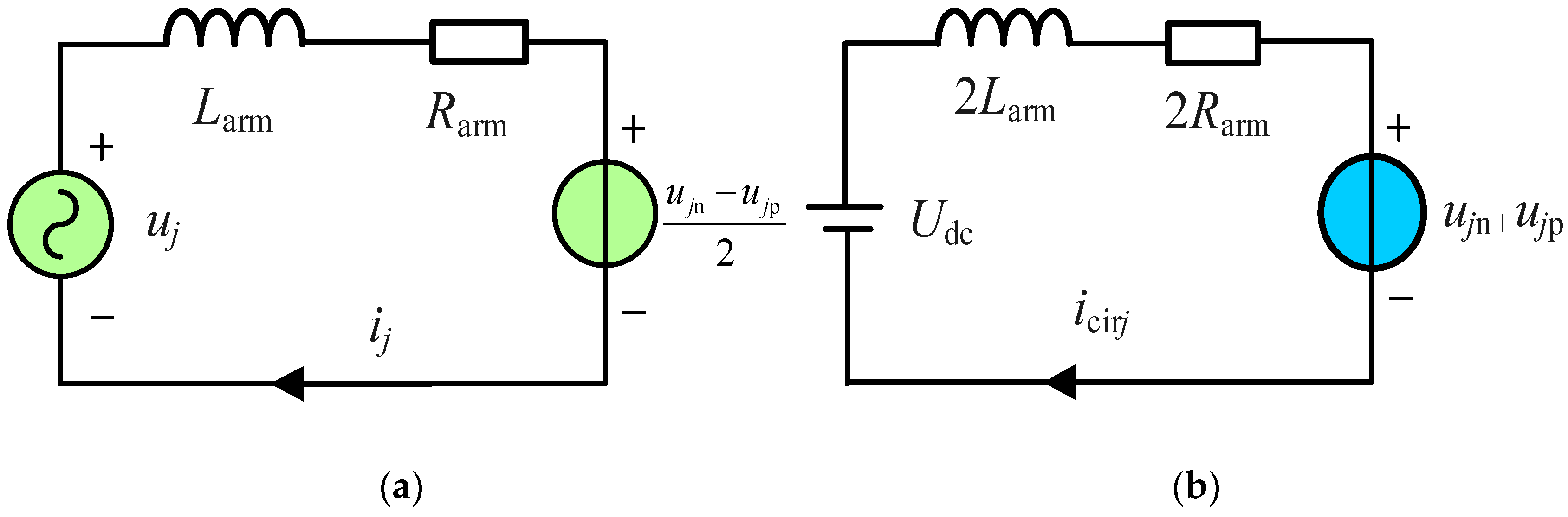
Figure 3.
The diagram of model predictive PI circulating current control strategy.

Figure 4.
The control diagram of PI control.

Figure 5.
Flowchart of modulation and voltage equalization strategy for upper arm.
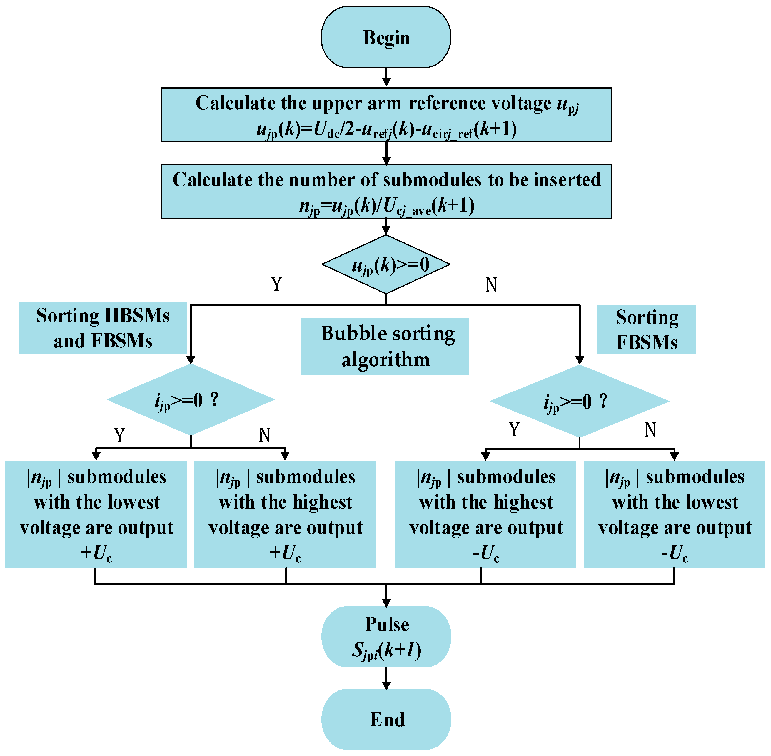
Figure 6.
Waveforms of MMC before and after the proposed MPPIC enabled. (a) Three phases circulating currents. (b) Three phases AC voltages. (c) Three phases AC currents. (d) The difference of average voltage of HBSM and FBSM. (e) Voltages of 20 capacitors in upper arm of phase-a.
Figure 6.
Waveforms of MMC before and after the proposed MPPIC enabled. (a) Three phases circulating currents. (b) Three phases AC voltages. (c) Three phases AC currents. (d) The difference of average voltage of HBSM and FBSM. (e) Voltages of 20 capacitors in upper arm of phase-a.
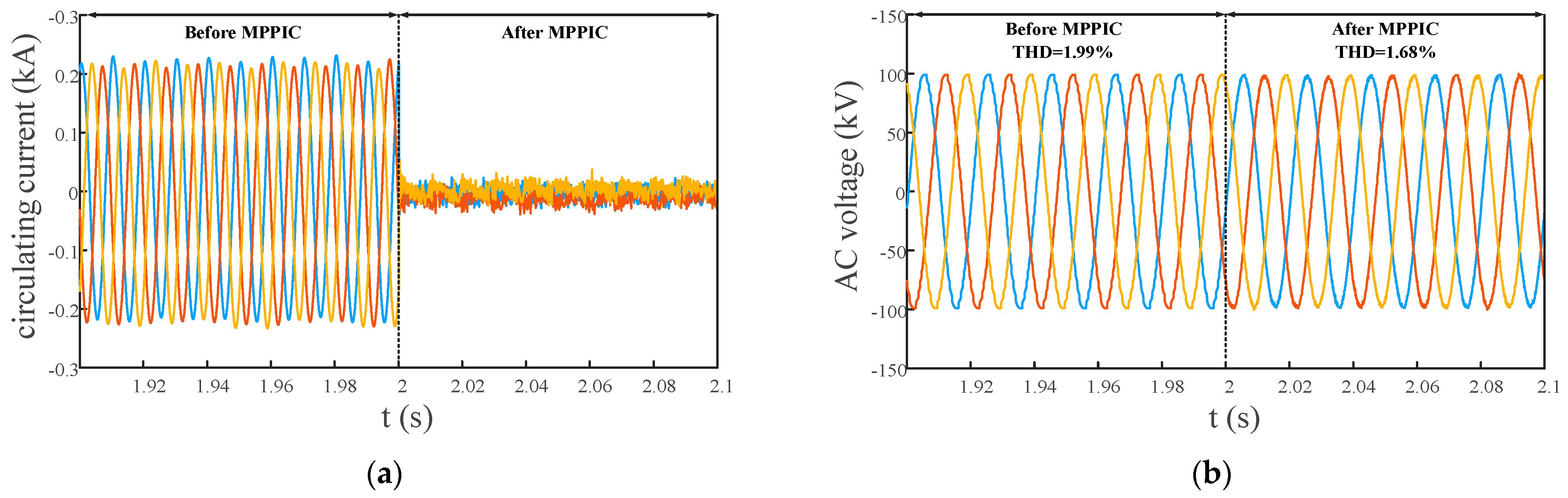
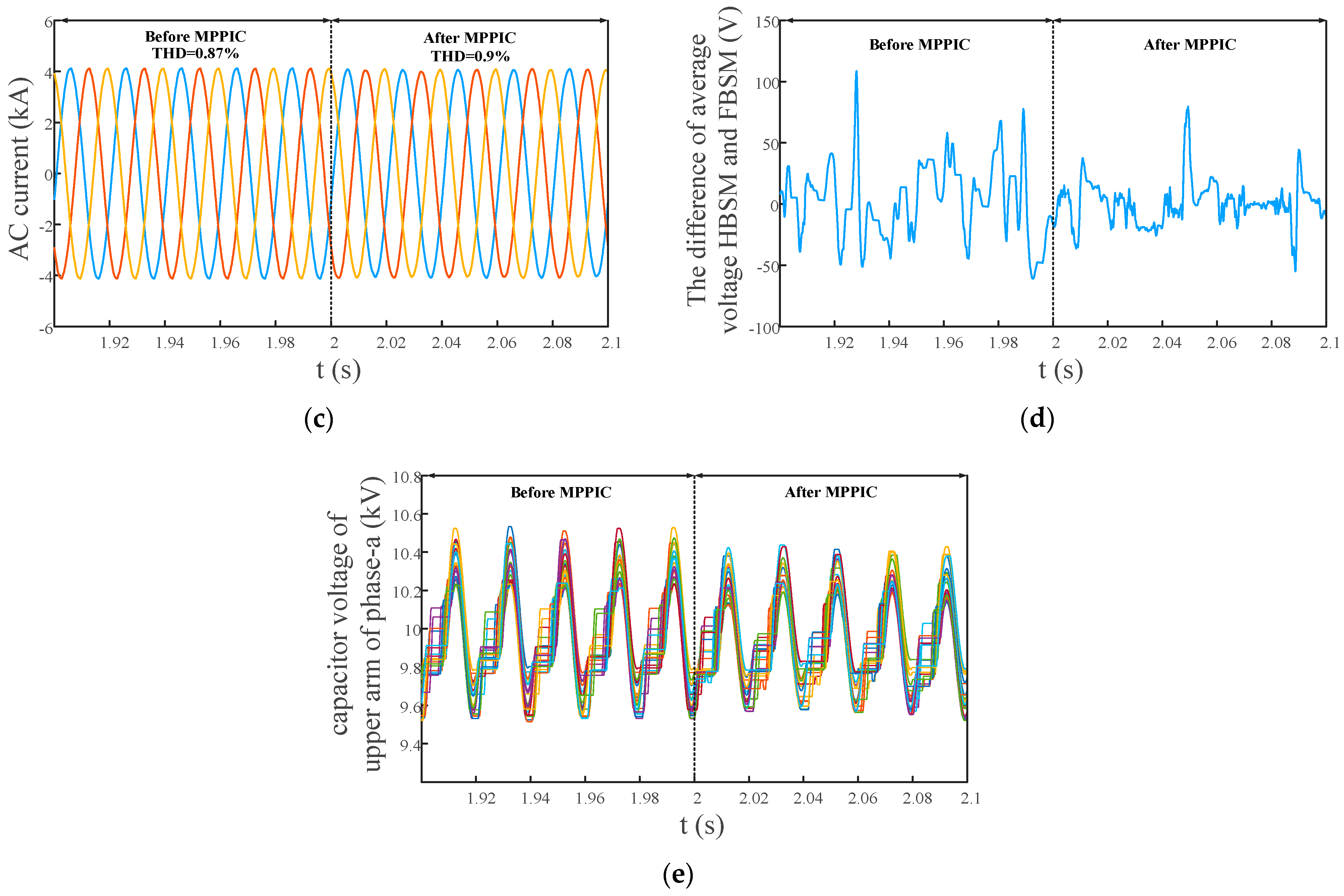
Figure 7.
Three phases circulating currents for for different m. (a) m = 1.15. (b) m = 1.25.

Figure 8.
FFT analysis of circulating current of phase-a before and after MPPIC is enabled for different m.
Figure 8.
FFT analysis of circulating current of phase-a before and after MPPIC is enabled for different m.
Figure 9.
Three phases waveforms of MMC before and after the control method deadbeat control. (a) Circulating current. (b) AC voltages. (c) AC currents.
Figure 9.
Three phases waveforms of MMC before and after the control method deadbeat control. (a) Circulating current. (b) AC voltages. (c) AC currents.

Table 1.
Comparison with existing methods.
| Methods | Coordinate System | The Number of Controllers | Computation | Response Speed |
|---|---|---|---|---|
| PI | dq | 2 | light | quick |
| PR | αβ | 2 | light | quick |
| Injection | abc | 0 | light | quick |
| MPC | abc | 0 | heavy | slow |
| MPPI | abc | 3 | medium | medium |
Table 2.
Simulation parameters of hybrid MMC.
| Item | Symbol | Value |
|---|---|---|
| DC voltage/kV | Udc | ±200 |
| Arm inductance/mH | Larm | 20 |
| The number of sub-modules in an arm | NH, NF | 10 + 10 |
| Sub-module capacitance/mF | C | 7 |
Table 3.
Simulation results of the proposed MPPIC and deadbeat control for m = 1.
| Methods | Proposed MPPIC | Deadbeat Control | |||
|---|---|---|---|---|---|
| before | after | before | after | ||
| Circulating current (A) | 2-th | 221.4 | 6.1 | 224.2 | 21.6 |
| 4-th | 34.2 | 4.3 | 34.2 | 18.7 | |
| AC current (THD, %) | 0.87 | 0.86 | 0.86 | 0.49 | |
| AC voltage (THD, %) | 1.99 | 1.68 | 2 | 1.04 | |
Disclaimer/Publisher’s Note: The statements, opinions and data contained in all publications are solely those of the individual author(s) and contributor(s) and not of MDPI and/or the editor(s). MDPI and/or the editor(s) disclaim responsibility for any injury to people or property resulting from any ideas, methods, instructions or products referred to in the content. |
© 2023 by the authors. Licensee MDPI, Basel, Switzerland. This article is an open access article distributed under the terms and conditions of the Creative Commons Attribution (CC BY) license (https://creativecommons.org/licenses/by/4.0/).
Share and Cite
MDPI and ACS Style
Jiang, Y.; Wang, W.; Shu, H.; Zhang, J. Model Predictive PI Circulating Current Control for Modular Multilevel Converter. Electronics 2023, 12, 2690. https://doi.org/10.3390/electronics12122690
AMA Style
Jiang Y, Wang W, Shu H, Zhang J. Model Predictive PI Circulating Current Control for Modular Multilevel Converter. Electronics. 2023; 12(12):2690. https://doi.org/10.3390/electronics12122690
Chicago/Turabian StyleJiang, Yaoxi, Wentao Wang, Hongchun Shu, and Junjie Zhang. 2023. "Model Predictive PI Circulating Current Control for Modular Multilevel Converter" Electronics 12, no. 12: 2690. https://doi.org/10.3390/electronics12122690
Note that from the first issue of 2016, this journal uses article numbers instead of page numbers. See further details here.