Abstract
High repetition rate lidar is typically equipped with a low-energy, high repetition rate laser, and small aperture telescopes. Therefore, it is small, compact, low-cost, and can be networked for observation. However, its data acquisition and control functions are generally not specially designed, and the data acquisition, storage, and control programs need to be implemented on an IPC (Industrial Personal Computer), which increases the complexity and instability of the lidar system. Therefore, this paper designs an integrated off-line echo signal acquisition system (IOESAS) for lidar developed based on SoC FPGA (System-On-Chip Field Programmable Gate Array). Using a hardware–software co-design approach, the system is implemented in a heterogeneous multi-core chip ZYNQ-7020 (integrated FPGA and ARM). The FPGA implements dual-channel echo data acquisition (gated counting and hardware accumulation). At the same time, the ARM performs laser control and monitoring, laser pointing control, pulse energy monitoring, data storage, and wireless transmission. Offline data acquisition and control software was developed based on LabVIEW, which can remotely control the status of the lidar and download the echo data stored in IOESAS. To verify the performance of the data acquisition system, IOESAS was compared with the photon counting card P7882 and MCS-PCI, respectively. The test results show that they are in good agreement; the linear correlation coefficients were 0.99967 and 0.99884, respectively. IOESAS was installed on lidar outdoors for continuous detection, and the system was able to work independently and stably in different weather conditions, and control functions were tested normally. The gating delay and gating width time jitter error are ±5 ns and ±2 ns, respectively. The IOESAS is now used in several small lidars for networked observations.
1. Introduction
Lidar uses the laser as a carrier; the laser interacts with particles or various gas molecules in the atmosphere; the data acquisition system receives the backscattered echo signal; and the atmospheric parameters are obtained through data inversion and analysis [1,2,3]. As a critical sensor in the field of active remote sensing, lidar has the advantages of high spatial and temporal resolution and continuous observation and is widely used in the areas of atmospheric composition analysis and environmental pollution monitoring [4,5]. In recent years, small high repetition rate lidar technology has been rapidly developed. It uses a high repetition rate, a low pulse energy laser, and a small aperture telescope, significantly reducing the lidar system’s size and weight. This also improves the stability and detection accuracy of the lidar, and it is suitable for installation at multiple locations for networked observations. Due to the low energy of the single pulse of the emitting laser and the small effective aperture of the telescope, the echo signal is extremely weak. Therefore, traditional analog detection methods cannot extract the useful signal from the background noise, and photon counting techniques [6] should be used, with the corresponding detectors being single-photon detectors [7] such as PMTs [8] (Photomultiplier Tubes) or APDs [9] (Avalanche Photodiodes) operating in Geiger mode. This technique uses the correlation of the backscattered signal to accumulate and count the echo photon pulses, extracting useful signals from the solar background noise and detector dark noise, and finally obtaining the intensity of the echo signal at different heights by statistics [7]. For example, the satellite-based lidar ICESat-2 (The Ice, Cloud, and Land Elevation Satellite-2) [10] uses photon counting detection. Topography along the orbiting seafloor is obtained to a depth of up to 40 m. In comparison, the sensitivity of the photon counting sensor (PMT in ICESat-2) is 2–3 orders of magnitude higher than that of the analog detection sensor APD [11]. The Shanghai Institute of Technology and Physics, Chinese Academy of Sciences, has developed a shipboard lidar for marine plankton observation. The data acquisition system also uses photon counting technology to improve detection accuracy [12]. This requires photon-counting cards that support gated counting and high repetition frequency triggering and are capable of continuous data acquisition. Currently, the main commercially available photon-counting cards are the MCS-PCI [13,14] and P7882 with PCI (Peripheral Component Interconnect) interface and the EASY-MCS with USB (Universal Serial Bus) interface. The Licel transient recorder [15,16] is a data acquisition device developed specifically for lidar with a combination of analog detection and photon counting functions, taking into account both near-field strong echo signals and far-field weak echo signals. It combines analog detection and photon counting functions, combining both low-level strong echo signals and high-altitude weak echo signals, and Licel uses an Ethernet interface to transmit the data. The modular design of the transient recorder allows for increased flexibility while also making it larger in size.
The photon-counting cards described above are generally large and need to be used in conjunction with an IPC (industrial control computer) [17]. For example, the collected data are transferred to the IPC via PCI or Ethernet bus. This makes the structure of the data acquisition system complex and reduces stability at the same time. In addition, the timing control of the lidar components also requires the involvement of an IPC. The components of the lidar need to work in an orderly manner under the action of the control system, such as status monitoring of the laser, laser pointing control [18], pulse energy monitoring [19,20,21], distance gate control [22], etc. In general, these functions need to rely on an IPC or a separate control card for implementation, which complicates the entire electronics system. In recent years, with the development of SoC FPGA technology, a collaborative design approach using hardware and software has been proposed. For example, the ZYNQ [23] family of heterogeneous multicore chips developed by Xilinx integrate FPGAs and ARMs, which are connected via a high-performance AXI bus. For specific applications, high-speed parallel processing tasks are implemented inside the FPGA via logic circuits (based on Verilog language), while the control program (based on C language) is executed in the ARM. This makes complex electronic systems compact, and the level of integration is increased while enhancing the stability of the system. The researchers have implemented a highly digitally integrated 2-D lidar system based on the heterogeneous chip ZYNQ, which enables the control of the lidar system and the data processing of the echo signal. Fully digital integration and compact dimensions were achieved [24].
In this paper, we propose an integrated off-line echo signal acquisition system (IOESAS), which is implemented based on the heterogeneous multi-core processor ZYNQ-7020 [25]. The integrated FPGA implements multi-channel photon counting, distance gate control, and laser pulse capture and triggering functions. The ARM is based on a serial operating mechanism and is responsible for the control of the laser, the energy monitoring of the pulses, data storage, and data transmission. The system adopts a software and hardware collaborative design approach [26], which integrates multi-channel data acquisition and lidar system control functions on a 115 mm × 141 mm circuit board, making the stability of the lidar system further improved.
2. Instruments and Methods
The self-developed data acquisition and control system is mounted on a small photon counting lidar, which was developed by the Key Laboratory of the Centre for Atmospheric Optics, Anhui Institute of Optics, Chinese Academy of Sciences. As shown in Figure 1, the lidar uses an Nd: YAG laser with an emission wavelength of 532.18 nm. The laser is expanded by a beam expander to enlarge the spot diameter by a factor of 20 to further reduce the divergence angle. The telescope is a reflective Cassegrain structure with a small aperture of 125 mm diameter to reduce the size of the overall system. To minimize the influence of solar background noise, a 0.5 mm diameter aperture stop is used to reduce the receiving field of view. The collimating lens changes the light into parallel light, which is then directed by several mirrors into a polarizing prism, resulting in a 532 nm parallel polarized signal and a vertically polarized signal. They are spectrally filtered by a 0.3 nm narrow-band interference filter, respectively, and finally, the light is focused by the lens to a single photon detector. The data acquisition and control system are implemented on a fully programmable heterogeneous multi-core platform ZYNQ-7020. The IOESAS first generates a trigger signal at a frequency of 3 kHz to the laser, while the pulse monitoring unit captures the moment of laser emission as a synchronization signal for the data acquisition system. The single photon detector converts the incident photon signal into an electrical pulse signal, which is gated and the signal is acquired by the data acquisition system according to preset parameters. In terms of control, the IOESAS performs functions such as state monitoring and control of the laser, laser pointing control, and monitoring of the pulse energy. The IOESAS corrects for errors caused by detector non-linearity and laser energy fluctuations by means of non-linearity correction and energy compensation. To facilitate outdoor installation and observation, the small lidar system uses a high repetition rate, low-energy laser, and a small-diameter telescope, with an integrated off-line echo signal acquisition system; thus, the overall size of the system is limited to 390 mm × 390 mm × 550 mm. The main performance parameters of its transmitting and receiving system are shown in Table 1.
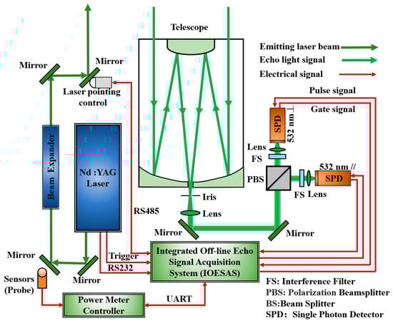
Figure 1.
Structure of high repetition rate lidar.

Table 1.
Parameters of high repetition rate lidar.
2.1. Lidar Automatic Control System
The lidar automatic control system is based on the heterogeneous multi-core processor ZYNQ-7020 (Xilinx Company, San Jose, CA, USA), which integrates an FPGA and an ARM A9 dual-core processor, both interconnected via the AXI high-speed bus. The main control functions are shown in the blue box in Figure 2 and include (1) laser monitoring and control: IOESAS communicates with the laser according to an agreed protocol, sends start/stop commands to control the state of the laser, and reads status data such as internal laser temperature/current; (2) laser pulse capture: the laser pulse capture circuit senses the moment of light emission through a PIN photodetector and outputs a pulse signal synchronized with the emitted laser, which is used as the start signal for the photon counting unit; (3) laser trigger: the FPGA outputs a periodic pulse signal as an external trigger signal for the laser, which can be intermittently emitted in order to make the laser operate stably; (4) distance gate control; the lidar near-field signal is strong and exceeds the measurement range of the detector, so the distance gate control unit is used to shield the strong near-field signal to prevent the detector from saturating and to reduce the effect of sky background noise; (5) GPS positioning: when observing in a network, the position of each lidar needs to be accurately recorded to better analyze the spatial variability of the aerosol layer; (6) data storage: the collected backscatter echo data are stored in a USB storage device to increase the portability of data transfer; (7) real-time clock: aerosol and cloud characteristics vary with time, so time stamping should be added to the data record; (8) light path collimation. Optical path collimation is required due to the deformation of the optical components (beam expander, reflectors, and dichroic mirrors), changes in ambient temperature, and the pointing jitter and drift of the laser itself, which can cause the optical axes of the transmitting and receiving optical systems to deviate from a certain angle; (9) wireless data transmission: data stored in non-volatile memory can be read wirelessly; (10) pulse energy monitoring: the laser energy fluctuates and decays, which increases the error in data inversion, and therefore needs to be monitored to compensate for this during data inversion.
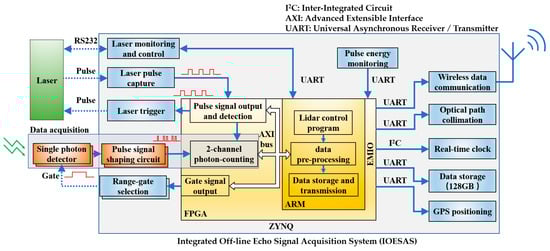
Figure 2.
Block diagram of integrated off-line echo signal acquisition system for lidar.
The circuit for each module of IOESAS is shown in Figure 3, with each significant unit structured as follows:
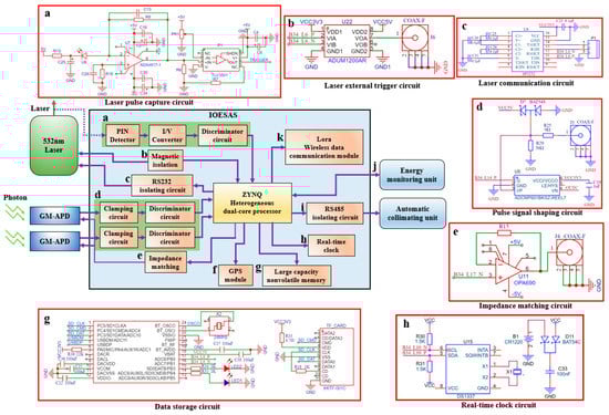
Figure 3.
Unit circuit of for lidar.
- (a)
- Laser pulse capture circuit: This circuit consists of a PIN detector, a trans-impedance amplifier circuit (current-to-voltage conversion), and a high-speed comparison circuit. The PIN detector is a DET10A2 [27] (Thorlabs, Newton, NJ, USA), which has a response rate of 0.26 A/W at 532 nm and a bandwidth of 350 MHz. The trans-impedance amplifier circuit consists of a FET amplifier ADA4817-1 [28] (Analog Device, Wilmington, MA, USA) combined with peripheral circuitry, which has a large bandwidth, high swing rate, and low noise. The core device of the high-speed comparison circuit is a TLV3501 [29] (Texas Instruments, Dallas, TX, USA) with a fast response delay of 4.5 ns and a rail-to-rail input-output function;
- (b)
- Laser external trigger circuit: The IOESAS outputs a periodic pulsed signal to trigger the laser to emit light. To extend the laser life, the trigger circuit can cause the laser to emit light intermittently. This function is performed by ZYNQ’s FPGA and ARM together;
- (c)
- Laser communication circuit: it consists of a level conversion chip SP3232 [30] (MaxLinear, Carlsbad, CA, USA) and capacitors to complete the conversion between the LVTTL level and RS232 level;
- (d)
- Pulse signal shaping circuit: It consists of a clamp protection circuit, a 50 Ω impedance matching circuit, and a high-speed comparator AD602 [31] (Analog Device, Wilmington, MA, USA). AD602 converts the input signal into a standard signal at LVTTL level with a delay time of about 3 ns;
- (e)
- Circuit for matching impedance: OPA690 [32] (Texas Instruments, Dallas, TX, USA) amplifies the gated signal (LVTTL level) produced from IOESAS to conduct pulse amplification and impedance matching, allowing the single photon detector to turn on the detecting function within a defined time;
- (f)
- GPS module interface circuit: the GPS inertial navigation sensor JY-GPSIMU (Wit motion, Shenzhen, China) is connected via a serial communication interface.
- (g)
- Data storage circuit: IOESAS stores the collected data on a USB flash disk with a maximum storage capacity of 128 GB;
- (h)
- Real-time clock circuit: the real-time clock chip DS1337 (Analog Device, Wilmington, MA, USA) provides clock/calendar information with an accuracy of seconds, and the data are transferred to the IOESAS via the I2C (Inter-Integrated Circuit) bus;
- (i)
- The IOESAS communicates via the RS485 bus with the Picomotor controller, which drives the adjustment frame 8822-AC [33] (New Port, Irvine, CA, USA), thus completing the adjustment of the laser beam azimuth and pitch angle of the laser beam.
- (j)
- Power is monitored using a PM101 [34] controller and an S470C thermal probe (Thorlabs, Newton, NJ, USA), which can detect wavelengths from 250 nm–10.6 µm with a resolution of 10 µW, a response time of 6.5 s and a maximum optical power density of 35 W/cm² (Avg). The IOESAS configures the PM101 via the serial port (including wavelength, range, resolution, etc.) and reads the power data;
- (k)
- Wireless communication circuit: Wireless data transmission is achieved by the Lora wireless communication module with data encryption and fixed-point transmission function. The module transmits at a power of 1000 mW, with a maximum transmission distance of 10 km.
The actual picture of the integrated off-line echo signal acquisition system for lidar is shown in Figure 4, with the following circuitry for each module: (1) regulated power supply circuit; (2) non-volatile memory circuit; (3) real-time clock circuit; (4) distance gate control circuit; (5) trigger output circuit; (6) trigger input circuit; (7) input pulse shaping circuit; (8) laser pointing control interface circuit; (9) GPS module interface circuit; (10) Lora wireless communication module; (11) laser communication circuit; and (12) Zynq-7020 core board.
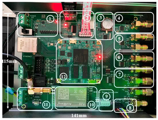
Figure 4.
The actual picture of integrated offline data acquisition and control system for lidar.
The gating delay and width parameters are sent from the computer to the data acquisition system, which is received by the ARM processor and sent to the FPGA via the AXI bus [35], where the FPGA generates the required signal via a counter, thus realizing the distance gate control function. Figure 5a shows the block diagram of the distance gate control unit. First, the active crystal generates a clock signal with a frequency of 50 MHz, which is multiplied by the MMCM [36] (Mixed-Mode Clock Manager) to generate a 200 MHz clock signal as the system’s master clock. The pulse capture circuit outputs a pulse signal synchronized to the laser pulse (1 in the figure), which is edge detected by the rising edge detection module and fed to the timing control circuit as a reference signal for the distance gate control unit. Two counters (counter 1 and counter 2) implement the delay and gating functions, respectively. The output signal is impedance matched by a voltage buffer, and the final output gating signal (2 in the figure) is connected to the single photon detector. Figure 5b shows the timing diagram of the output pulse signal of the main node. t1 is the delay time of the outgoing laser after the laser receives the external trigger signal, t2 is the delay time after the outgoing laser (corresponding to the detection starting point), and t3 is the gating width (corresponding to the detection length). When detecting echo signals from 1.2 km to 13.2 km, t2 and t3 are 4 μs and 40 μs, respectively.
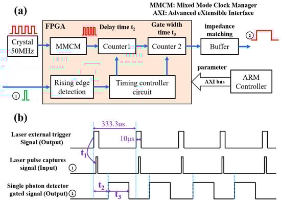
Figure 5.
Distance gate control: (a) schematic diagram; (b) working sequence diagram.
2.2. Data Acquisition System of Lidar
The photon counting principle of the lidar return signal works as shown in Figure 6. The laser is excited by the trigger signal, and the backscattered echo photon signal is received by the single photon detector, which outputs an electrical pulse signal. Due to the low number of emitted photons from the single photon detector during a single acquisition, the signal-to-noise ratio of the emitted signal is low. The signal-to-noise ratio improves proportionally to the number of echo pulses accumulated N times, but as N increases, the time resolution decreases and should be set according to the time resolution requirement in practice. To avoid the influence of dead time on the counting accuracy (pulse omission due to counting channel switching), two counters are used in a “ping-pong” mode of operation [37,38] (indicated by different colors in the diagram).
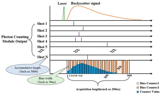
Figure 6.
Photon counting principle of lidar echo signal.
The principle of the echo signal acquisition system based on hardware and software collaboration design is shown in Figure 7. As can be seen from the diagram, the FPGA and ARM share the work, the former completes the processing of high-speed signals (such as echo signal photon counting, etc.); the latter realizes the data storage, human–machine interaction, and other processes; and they complete efficient communication through interrupt signal and AXI bus.
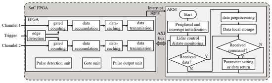
Figure 7.
Echo signal acquisition system principle diagram based on SoC FPGA.
The photon counting system mainly consists of a heterogeneous multi-core chip ZYNQ and several peripheral circuits, as shown in Figure 8. The specific workflow of the system is as follows: the pulse signal output from the single photon detector is input directly to the PL (Programmable Logic) after pulse shaping (a in Figure 8). The trigger signal output from the pulse capture circuit is identified by the rising edge detection module (b in Figure 8), where the echo signal a is input to the counter to complete counting within a bin period, and the trigger signal b is input to the timing controller as the start signal for a single round of counting. The timing controller is the control center for the entire counting logic and generates the gating signal c for counter switching (the two counters work in split time to eliminate the effect of dead time), the read/write control signal for the dual-port RAM and the address generation signal f. Under the action of the write enable and the incremental address signal f, the count values are sequentially stored in the dual-port RAM cache. In the next counting cycle (under the next trigger signal), the 32-bit adder reads the data from the RAM for the previous round, and the accumulated data e are written back to the RAM. After completing the accumulation count (e.g., 5000 times), the timing controller outputs the count completion signal g to inform the interface converter to work. At the same time, on the rising edge of the clock, the read enable signal and the incremental address signal f are output to the dual-port RAM, and the data are read out, in turn, and loaded into the AXI_GP bus via the interface converter module. The data are finally sent via the high-speed AXI bus to the DDR3 SDRAM connected to the PS (Processing system) for caching. Simultaneously, the interface conversion module outputs the conversion completion flag signal i as an interrupt signal to the PS, informing the ARM that the data are being processed in a timely manner. The APU2 core of the PS then reads the sampled data from the SDRAM to complete the pre-processing work, and the processing results are stored in non-volatile memory (128 GB USB flash disk). The external energy monitoring module is received via the UART module in the PL (implemented by calling the IP core AXI UART 16550) and converted to the AXI Lite bus for transmission to the PS. In order to improve the continuity of the data processing, the acquisition and processing of the energy signal is made by the APU1 core of the PS. The two cores communicate with each other via messages.
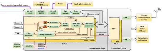
Figure 8.
Block diagram of photon counting system based on ZYNQ.
3. Experimental Results and Analysis
3.1. Lidar System Control and Status Monitoring
Figure 9 shows the software interface of the host computer written in LabVIEW. The waveform display area is located in the middle area, where the upper part shows the echo signals of the 532 nm parallel and vertical channels read from memory, and the lower part shows the power signals returned from the power meter. The parameter setting and status display area for each function module is located on both sides of the software. The left side is the area for wireless communication, laser status monitoring and control, and laser pulse power monitoring; the right side is the functional area for distance gate control, optical path collimation, and memory data reading.
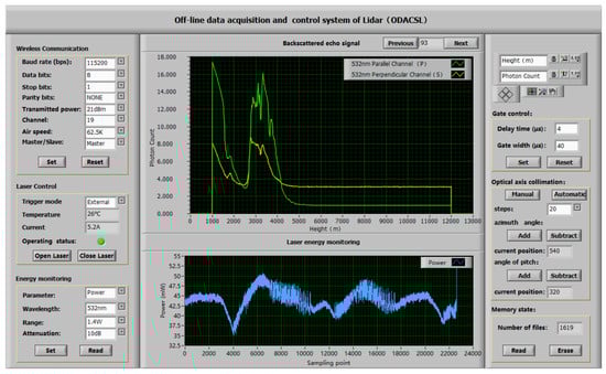
Figure 9.
Remote control software of IOESAS based on LabVIEW.
To test the accuracy and stability of the distance gate control unit, the gating delay and gating width of the FPGA output were statistically tested with a signal generator (Keysight 33500B) and an oscilloscope (Keysight DSOX3024T). Firstly, the gating delay and gating width were randomly set to 55 μs and 245 μs. Figure 10a shows the laser pulse synchronization signal in red and the gating output signal in green, which indicates that the output function is normal. As seen in the histogram in Figure 10b, the measured minimum delay time is 54.995 μs, and the maximum delay time is 55.005 μs, with a gating delay error of ±5 ns, corresponding to a spatial distance error of 1.5 m. As seen in the histogram in Figure 10c, the minimum gating width is 244.998 μs, and the maximum gating width is 245.001 μs, with an error of ±2 ns, corresponding to a distance error of only 0.6 m, which satisfies the lidar requirements for the distance selective pass function.
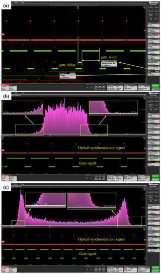
Figure 10.
Test of gated delay and gated width time.(a) gated delay histogram. (b) gated width histogram. (c) gated width statistical histogram.
3.2. Data Acquisition Function Test
After the system is powered on, the PS acts as the master control center, completes peripheral initialization and system self-test, and then sends counting-related parameters to the PL via the AXI_Lite bus, which is a lightweight address-mapped transmission interface with a single-transmission mechanism that takes up fewer logic resources and is suitable for the transmission of time-sensitive control commands. The PS serves as master role, being the sender of data, and PL serves as the slave. Bin time, bins length, and accumulation times are set to 200 ns, 2000, and 2000, respectively. As shown in Figure 11a, the diagram shows the logical signals of the AXI write address channel captured by the ILA (Virtual Logic Analyzer). First, the PS pulls the axi_awvalid signal high and sends a write address request to PL, PL pulls the aw-ready signal high immediately after receiving the request, data transmission starts when axi_awvalid and axi_awready are jointly valid. The PS sends data three times through the write address channel (AW Channel). The PS sends data three times through the write data channel (W Channel) with addresses 43c0000, 43c0004, and 43c0008, respectively; the value of the corresponding address is 20, 2000, and 2000, as shown in Figure 11b. As the master clock frequency is 100 MHz, the first parameter 20 means 200 ns. At the same time, the data sending process unfolds simultaneously, as shown in Figure 11b. After the host request and the slave response (axi_awvalid and axi_awready pull-up) are both valid, the PS sends the bins widths, length, and accumulative counts parameters required for the counting function to the PL, whereupon the counting logic in the PL begins to operate. Figure 11c shows the waveform of the backward scattered echo signal after multiple triggering and accumulation when the distance gate is fully open. When the two-channel photon counting process is finished, the channel2_flag signal goes from low to high, triggering the GPIO interrupt of the ARM controller, which reads the data and pre-processes them. channel2_address outputs the sequentially increasing address signal, and channel2_count outputs the accumulated echo signal.
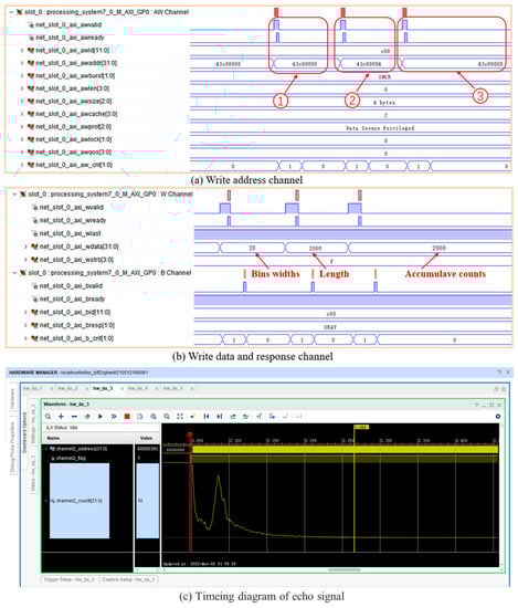
Figure 11.
Waveform captured by logic analyzer.
To verify the performance of the photon counting function, the IOESAS and the P7882 were simultaneously placed in a lidar with a low energy laser for testing. The P7882 is a multi-channel photon counter developed by FAST ComTec, Germany, with a maximum count rate of 350 MHz and a dead time of 0. Figure 12a shows the comparative experi-mental test environment. To prevent crosstalk and reflection of the high-speed pulse sig-nal, transmission lines have a characteristic impedance of 50 Ω. As the minimum operat-ing bins width of the P7882 (dual-channel version) is 200 ns (corresponding to a vertical resolution of 30 m), the acquisition parameters of the photon counting system were modi-fied accordingly, i.e., bins width, sampling length, and cumulative count were 200 ns, 2000, and 2000. A comparison of the echo signal waveforms is shown in Figure 12c, as can be seen from the figure, the relative positions of the two are basically the same in the hori-zontal and vertical directions of the coordinate axes without any obvious offset, indicating that the time error of IOESAS is small (reflected in the horizontal direction) and the count-ing accuracy is high (reflected in the vertical direction). As can be seen from the Figure 12d, the linear correlation coefficient is as high as 0.99967, and the linear fit equation is y = 1.00346x + 0.0524.
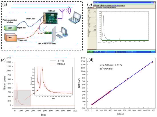
Figure 12.
A comparative test of IOESAS and P7882.
To further test the data acquisition accuracy of the IOESAS, the IOESAS and the MCS-PCI photon counting card were installed in another lidar for comparative verifica-tion, with a bins time of 100 ns, a bins length of 1000, and a cumulative count of 3000. The test results are shown in Figure 13. Figure 13a shows a comparison of the echo signals, the data is in good agreement. As seen in Figure 13b, the correlation coefficient is 0.99884. This further demonstrates the reliability of photon counting of IOESAS.
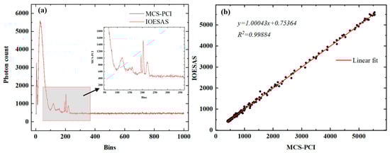
Figure 13.
A comparative test of IOESAS and MCS-PCI. (a) Comparison of echo signals. (b) Linear fitting graph.
To understand the linearity of photon counting, we use a signal generator to generate two pulse signals whose frequency is modified by the amplitude of the triangle wave.The frequency range of the output signal of channel 1 is 0~28 MHz, and the frequency range of the output signal of channel 2 is 10~38 MHz. The waveform display software is written based on LabVIEW 2020 software. The test results are shown in Figure 14. It can be shown that under the action of the triggering signal, the IOESAS can normally collect the pulse signal with changing frequency, The red and green lines in the figure represent the signals for channel 1 and channel 2 respectively. The peak and valley values of counting are consistent with the set value. The rising and falling slopes of the waveform also show that the photon counting system has good linearity.
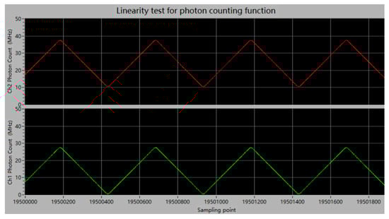
Figure 14.
Linearity test for photon counting function.
To quantify the linearity of the photon counter card, we used Signal Generator 1 (Keysight 33500B) to output a 3 kHz trigger signal and Signal Generator 2 (NF WF1968) to output a narrow pulse signal (pulse width 10 ns) varying from 0–60 MHz. The bins width, bins length, and number of accumulations for photon counting were set to 100 ns, 2000, and 3000, respectively. Test results are shown in Figure 15, the mean value of the output frequency is in good agreement with the ideal value, with a correlation of 0.9999 and a small SD (standard deviation). The relatively large standard deviation at odd frequencies is due to the fact that when the counters are operating in ping-pong mode, the switching frequency of the two counters is not multiplied by the frequency being measured. In practice, the pulse signal output from the single photon detector is random; therefore, this problem does not occur.
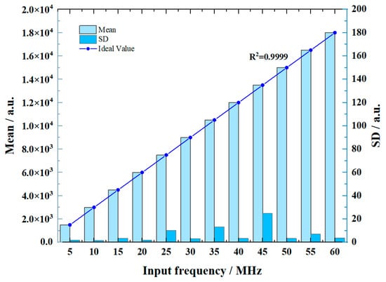
Figure 15.
Statistical test of photon counting linearity.
In addition, IOESAS was installed on an airborne lidar for flight tests. The temperature difference between the ground and the air during the flight test was approximately 30 °C, the aircraft had an effective value of nearly 2.5 m/s2 of vibration acceleration in the vertical direction, and electrical equipment on the aircraft generated EMI (Electromagnetic Interference) signals. The experimental results show that the impact of different temperature, vibration, and EMI environments on IOESAS is low and that it can be used properly for high repetition rate lidar detection.
3.3. Lidar Observation Results
When the laser is transmitted in the atmosphere, absorption, and scattering effects occur when it encounters aerosol particles or atmospheric molecules, so the backscattered echo signal is related to the aerosol or molecular concentration. The power of the echo signal received by lidar at a distance z from the ground is given by the following equation [39,40]:
where denotes the received atmospheric backscattered signal power at height z; K is the lidar system constant, which is positively correlated with the laser emission energy, telescope aperture, and other parameters; and are the backscattering coefficients of aerosol particles and air molecules at height z; and and are the extinction coefficients of aerosol particles and air molecules, respectively. The echo signal strength decays with distance squared, and with the large aerosol concentration near the ground, the detector is easily saturated during near-field detection, and if a far-field signal needs to be detected, the detector needs to be gated and controlled. After the laser has warmed up for 30 min, The power meter probe is placed at the end of the reflector with a power of P0 at the beginning and the laser power of PM after a long period of operation, then
where is the normalized relative rate of change of energy, , and the lidar echo signal power is corrected according to the value of . Figure 16a shows the high repetition rate, low energy lidar with IOESAS installed and Figure 16b shows the laser energy is being tested.
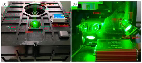
Figure 16.
Experimental measurement (a) high repetition rate lidar. (b) laser energy test.
The IOESAS was tested on a high repetition rate lidar (Figure 1) with a gating delay time of 4 μs and a gating width time of 40 μs (corresponding detection range of 1.2 km to 13.2 km). The measured echo photon data and laser power data were stored on a USB flash disk (128 GB capacity), and the data in the storage device were read wirelessly. The distance squared corrected signal [41] was calculated by MATLAB 2017 software for several days. Figure 17 shows the spatial and temporal distribution of the distance-squared corrected signals for the 532 nm parallel and 532 nm vertical channel, respectively.
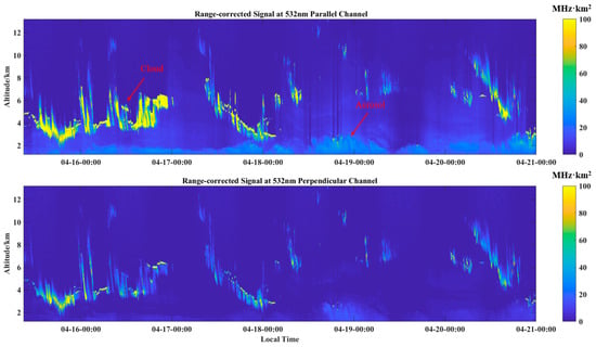
Figure 17.
Spatio-temporal changes of distance square correction signals collected.
On 16 April 2022, there were thick clouds throughout the day, and the clouds were mainly distributed in the range of 2–6 km. Distance squared correction signal exceeds 100 MHz·km2 at maximum. On 19 April 2022, there were very few clouds, and the aerosol concentration near the ground was relatively large. The variation in near-surface aerosol concentration with time is more apparent, and its distance-squared correction signal is much smaller than that of clouds, indicating a stronger backscattered echo signal from clouds. The detected echo signal by IOESAS shows that the lidar can clearly distinguish between aerosols and clouds. The lidar with IOESAS is capable of continuous, stable running. After analyzing the received data, it was found that IOESAS was able to collect and store data independently without an IPC, and no data were missed.
4. Conclusions
We have developed a fully integrated off-line signal acquisition system for high repetition rate lidar applications, as opposed to conventional lidar data acquisition systems which require IPC etc. It is based on SoC FPGA technology and integrates echo signal acquisition and control functions (e.g., distance gate control) through a hardware–software co-design approach. It can be independently driven and controlled for lasers, single-photon detectors, etc., with echo signal acquisition and storage functions. Triangular wave sweeping of narrow pulse signals in IOESAS using a two-channel signal generator gives good linearity of the data. Meanwhile, the gating delay accuracy of IOESAS is ±5 ns and the gating width time accuracy is ±2 ns, corresponding to a distance error of 1.5 m and 0.6 m, respectively, obtained via histogram analysis on an oscilloscope. Finally, to verify the photon counting accuracy in a real experimental environment, IOESAS was installed on a high repetition rate lidar for testing and compared with commercial P7882 and MCS-PC. The linear correlation coefficients is 0.99967 and 0.99884 respectively.
In addition, unlike the signal acquisition system of conventional lidar, IOESAS can perform lidar control, data acquisition, data storage, and wireless transmission functions independently, i.e., without the involvement of an IPC. The optical path collimation system and energy monitoring system ensure the detecting accuracy of the lidar. The system is capable of continuous and stable operation in unattended outdoor areas. Lidar control and data reading can be operated remotely via the host computer software.
It should be noted that IOESAS has only been measured for temperature, humidity, vibration, and EMI in ground-based and airborne high repetition rate lidar applications. The IOESAS has not yet been tested in multi-site or harsh environments, but both ground and airborne experiments have shown that the IOESAS can meet the detection requirements of high repetition rate lidars. In conclusion, we believe that the IOESAS will enable compact and efficient electronic systems for high repetition rate lidars.
Author Contributions
L.C.: conceptualization, investigation, methodology, software, data curation, writing—original draft; C.X.: conceptualization, resources, supervision, writing—review and editing. All authors have read and agreed to the published version of the manuscript.
Funding
This work was supported in part by the Key Project of Natural Science Research in Colleges and Universities of Anhui Province (No. 2022AH052136); Project of Anhui Province Key Laboratory of Simulation and Design for Electronic Information System (No. 2020ZDSYSYB05).Project of Anhui Province Key Laboratory of Target Recognition and Feature Extraction (No. TRFE2021A003); 2020 Project of Hefei Normal University Provincial Research Platform (No. 2020PT12); and Anhui Pro-vincial Quality Engineering Project of Higher Education Institutions (No. 2021jyxm1237). The Strategic Priority Research Program of the Chinese Academy of Sciences (No. XDA17040524).
Institutional Review Board Statement
Not applicable.
Informed Consent Statement
Not applicable.
Data Availability Statement
Not applicable.
Acknowledgments
In this section, we would like to thank the Key Laboratory of Atmospheric Optics, the Anhui Institute of Optics and Fine Mechanics, Chinese Academy of Sciences, for experimental facilities.
Conflicts of Interest
The authors declare no conflict of interest.
References
- Ceolato, R.; Berg, M.J. Aerosol light extinction and backscattering: A review with a lidar perspective. J. Quant. Spectrosc. Radiat. Transf. 2021, 262, 107492. [Google Scholar] [CrossRef]
- Xie, C.; Zhao, M.; Wang, B.; Zhong, Z.; Wang, L.; Liu, D.; Wang, Y. Study of the scanning lidar on the atmospheric detection. J. Quant. Spectrosc. Radiat. Transf. 2015, 150, 114–120. [Google Scholar] [CrossRef]
- Comeron, A.; Munoz-Porcar, C.; Rocadenbosch, F.; Rodriguez-Gomez, A.; Sicard, M. Current Research in Lidar Technology Used for the Remote Sensing of Atmospheric Aerosols. Sensors 2017, 17, 1450. [Google Scholar] [CrossRef] [PubMed]
- Zhao, Y.; Wang, Y.; Liang, C.; Wang, J.; Fang, J.; Zhou, M. Study of Mixed Pollution of Haze and Dust in Jinan Based on LiDAR. Photonics 2022, 9, 144. [Google Scholar] [CrossRef]
- Xian, J.; Sun, D.; Xu, W.; Han, Y.; Zheng, J.; Peng, J.; Yang, S. Urban air pollution monitoring using scanning Lidar. Environ. Pollut. 2020, 258, 113696. [Google Scholar] [CrossRef] [PubMed]
- Wang, C.-H.; Wang, A.-Y.; Tao, Y.-L.; Li, X.; Peng, H.; Meng, P.-B. Development and test of photon counting lidar. In Proceedings of the 4th Seminar on Novel Optoelectronic Detection Technology and Application, Nanjing, China, 4–26 October 2017. [Google Scholar]
- Du, B.-C.; Li, Z.-H.; Shen, G.-Y.; Zheng, T.-X.; Zhang, H.-Y.; Yang, L.; Wu, G. A Photon-Counting Full-Waveform Lidar. Chin. Phys. Lett. 2019, 36, 094201. [Google Scholar] [CrossRef]
- Xiang, Y.-Y.; Ma, Y.; Guo, G.-F.; Jing, Q.; Li, S. The photon detection mode of photomultiplier tubes considering the pulse height distribution. J. Infrared Millim. Waves 2023, 42, 88–101. [Google Scholar] [CrossRef]
- Williams, G.M.; Huntington, A.S. Single Photon Counting Linear Mode Avalanche Photodiode Technologies. In Proceedings of the Conference on Infrared Sensors, Devices, and Applications and Single Photon Imaging II, San Diego, CA, USA, 22–25 August 2011. [Google Scholar]
- Magruder, L.A.; Brunt, K.M. Performance Analysis of Airborne Photon-Counting Lidar Data in Preparation for the ICESat-2 Mission. IEEE Trans. Geosci. Remote Sens. 2018, 56, 2911–2918. [Google Scholar] [CrossRef]
- Yang, J.; Ma, Y.; Zheng, H.Y.; Gu, Y.F.; Zhou, H.; Li, S. Analysis and Correction of Water Forward-Scattering-Induced Bathymetric Bias for Spaceborne Photon-Counting Lidar. Remote Sens. 2023, 15, 931. [Google Scholar] [CrossRef]
- Shen, X.; Kong, W.; Chen, P.; Chen, T.; Huang, G.H.; Shu, R. A Shipborne Photon-Counting Lidar for Depth-Resolved Ocean Observation. Remote Sens. 2022, 14, 3351. [Google Scholar] [CrossRef]
- EASY-MCS Multichannel Scaler. Available online: https://www.ortec-online.com/products/electronics/counters-timers-rate-meter-and-multichannel-scaling-mcs/easy-mcs (accessed on 9 January 2022).
- Mianyun, C.; Peng, Z.Y. Lidar control system based on MCS-pci. J. Optoelectron. Laser 2008, 19, 566–568. [Google Scholar]
- De Young, R.; Carrion, W.; Pliutau, D. A compact mobile ozone Lidar for atmospheric ozone and aerosol profiling. In Proceedings of the Conference on Lidar Technologies, Techniques, and Measurements for Atmospheric Remote Sensing X, Amsterdam, The Netherlands, 22–24 September 2014. [Google Scholar]
- Zhang, Y.; Yi, F.; Kong, W.; Yi, Y. Slope characterization in combining analog and photon count data from atmospheric lidar measurements. Appl. Opt. 2014, 53, 7312–7320. [Google Scholar] [CrossRef]
- Cheng, L.; Xie, C.; Zhao, M.; Li, L.; Yang, H.; Fang, Z.; Chen, J.; Liu, D.; Wang, Y. Design of Lidar Data Acquisition and Control System in High Repetition Rate and Photon-Counting Mode: Providing Testing for Space-Borne Lidar. Sensors 2022, 22, 3706. [Google Scholar] [CrossRef] [PubMed]
- Li, L.; Xie, C.; Zhang, Z.; Wang, B.-X.; Zhuang, P.; Chu, Y.; Fang, Z.; Shao, J. Development and observational studies of scanning coaxial Mie lidar. In Proceedings of the 6th Symposium on Novel Optoelectronic Detection Technology and Applications, Beijing, China, 3–5 December 2019. [Google Scholar]
- Refaat, T.F.; Petros, M.; Remus, R.; Yu, J.; Singh, U.N. Laser energy monitor for double-pulsed 2-um IPDA lidar application. In Proceedings of the Lidar Technologies, Techniques, and Measurements for Atmospheric Remote Sensing X, Amsterdam, The Netherlands, 22–24 September 2014; pp. 20–27. [Google Scholar]
- Hu, W.; Liu, J.; Zhu, Y.; Dong, J.; Ma, X.; Li, S.; Zhang, J.; Zhu, X.; Chen, W.J.A.O. Analysis of energy monitoring for a double-pulsed CO2 integrated path differential absorption lidar at 1.57 μm. Appl. Opt. 2019, 58, 616–625. [Google Scholar] [CrossRef]
- Harrabi, K.; Gasmi, K.; Mekki, A.; Bahlouli, H.; Kunwar, S.; Milosevic, M.V. Detection and Measurement of Picoseconds-Pulsed Laser Energy Using a NbTiN Superconducting Filament. IEEE Trans. Appl. Supercond. 2023, 33, 2400205. [Google Scholar] [CrossRef]
- Molchanov, P.A.; Contarino, V.M.; Concannon, B.M.; Asmolova, O.V.; Podobna, Y.Y. Nanosecond gated PMT for LIDAR-RADAR applications. In Proceedings of the Conference on Infrared and Photoelectronic Imagers and Detector Devices, San Diego, CA, USA, 13–14 August 2006. [Google Scholar]
- Han, Y.; Virupakshappa, K.; Pinto, E.V.S.; Oruklu, E. Hardware/Software Co-Design of a Traffic Sign Recognition System Using Zynq FPGAs. Electronics 2015, 4, 1062–1089. [Google Scholar] [CrossRef]
- Huang, J.; Ran, S.; Wei, W.; Yu, Q. Digital Integration of LiDAR System Implemented in a Low-Cost FPGA. Symmetry 2022, 14, 1256. [Google Scholar] [CrossRef]
- Patil, S.; Singh, B.; Borwankar, R.; Margala, M. Novel Pulse Detection System Using Differentiation: Prototyping and Experimental Results. In Proceedings of the 20th IEEE Interregional NEWCAS Conference (IEEE NEWCAS), Quebec City, QC, Canada, 19–22 June 2022; pp. 45–49. [Google Scholar]
- Farhat, W.; Faiedh, H.; Souani, C.; Besbes, K. Real-Time Hardware/Software Co-Design of a Traffic Sign Recognition System Using Zynq FPGA. In Proceedings of the 11th International Design and Test Symposium (IDT), Hammamet, Tunisia, 18–20 December 2016; pp. 302–307. [Google Scholar]
- DET10A2—Si Detector, 200–1100 nm, 1 ns Rise Time, 0.8 mm². Available online: https://www.thorlabs.com/thorproduct.cfm?partnumber=DET10A2#ad-image-0 (accessed on 5 April 2023).
- Single, Low Noise, 1 GHz FastFET Op Amplifier. Available online: https://www.analog.com/en/products/ada4817-1.html (accessed on 5 April 2023).
- 4.5 ns, Rail-to-Rail, High Speed Comparator with Shutdown. Available online: https://www.ti.com/product/TLV3501 (accessed on 4 April 2023).
- True 3.0 V to 5.5 V RS-232 Transceivers. Available online: https://assets.maxlinear.com/web/documents/sipex/datasheets/sp3222e_sp3232e.pdf (accessed on 5 April 2023).
- Dual, Low Noise, Wideband Variable Gain Amplifier, −10 dB to +30 dB Gain. Available online: https://www.analog.com/en/products/ad602.html (accessed on 8 March 2023).
- Wideband, Voltage Feedback Operational Amplifier With Disable. Available online: https://www.ti.com/product/OPA690 (accessed on 2 April 2023).
- Piezo Mirror Mount, Clear Edge, 2.0 in. Diameter, 2-Axis. Available online: https://www.newport.com.cn/p/8822 (accessed on 15 March 2023).
- Power and Energy Meter Interfaces with External Readout. Available online: https://www.thorlabs.com/newgrouppage9.cfm?objectgroup_id=4037&pn=PM101#8135 (accessed on 5 April 2023).
- Vivado AXI Referenc. Available online: https://docs.xilinx.com/v/u/en-US/ug1037-vivado-axi-reference-guide (accessed on 11 March 2023).
- Mixed-Mode Clock Manager (MMCM) Module. Available online: https://www.xilinx.com/products/intellectual-property/mmcm_module.html#overview (accessed on 5 March 2023).
- Xia, J.; Zhao, X.; Wu, J. Design and Implementation of Multi-channel Video Monitor System Based on FPGA. In Proceedings of the 2nd International Symposium on Computer Network and Multimedia Technology (CNMT), Wuhan, China, 24–26 December 2010; pp. 457–460. [Google Scholar]
- Ma, L.; Song, K.; Yang, J.; Cao, P. Hardware implementation of a real-time data processing algorithm in marine engineering data acquisition. In Proceedings of the International Conference on Computational Materials Science (CMS 2011), Guangzhou, China, 17–18 April 2011. [Google Scholar]
- Fernald, F.G. Analysis of Atmospheric Lidar Observations—Some Comments. Appl. Opt. 1984, 23, 652–653. [Google Scholar] [CrossRef] [PubMed]
- Yang, H.; Fang, Z.; Cao, Y.; Xie, C.; Zhou, T.; Wang, B.; Xing, K.; Lolli, S. Impacts of Transboundary Dust Transport on Aerosol Pollution in the Western Yangtze River Delta Region, China: Insights Gained From Ground-Based Lidar and Satellite Observations. Earth Space Sci. 2021, 8, e2020EA001533. [Google Scholar] [CrossRef]
- Comeron, A.; Sicard, M.; Rocadenbosch, F. Wavelet Correlation Transform Method and Gradient Method to Determine Aerosol Layering from Lidar Returns: Some Comments. J. Atmos. Ocean. Technol. 2013, 30, 1189–1193. [Google Scholar] [CrossRef]
Disclaimer/Publisher’s Note: The statements, opinions and data contained in all publications are solely those of the individual author(s) and contributor(s) and not of MDPI and/or the editor(s). MDPI and/or the editor(s) disclaim responsibility for any injury to people or property resulting from any ideas, methods, instructions or products referred to in the content. |
© 2023 by the authors. Licensee MDPI, Basel, Switzerland. This article is an open access article distributed under the terms and conditions of the Creative Commons Attribution (CC BY) license (https://creativecommons.org/licenses/by/4.0/).