Article

Design of Sensorless Speed Control System for Permanent Magnet Linear Synchronous Motor Based on Fuzzy Super-Twisted Sliding Mode Observer

School of Electrical Engineering, Hebei University of Science and Technology, Shijiazhuang 050018, China
*
Authors to whom correspondence should be addressed.
Electronics 2022, 11(9), 1394; https://doi.org/10.3390/electronics11091394
Submission received: 26 March 2022 / Revised: 24 April 2022 / Accepted: 24 April 2022 / Published: 27 April 2022
(This article belongs to the Special Issue Sliding Mode Control in Dynamic Systems)

Abstract

:
To improve the tracking capability and sensorless estimation accuracy of a permanent magnet linear synchronous motor (PMLSM) control system, a sensorless control system based on a continuous terminal sliding mode controller (CT-SMC) and fuzzy super-twisted sliding mode observer (F-ST-SMO) was designed. Compared with a conventional slide mode control, CT-SMC can reach the equilibrium point in limited time to ensure the continuity of control and achieve fast tracking of reference speed. Based on the PMLSM design of F-ST-SMO, a super-twisted sliding mode algorithm is used to replace the traditional first order sliding mode algorithm. Meanwhile, fuzzy rules are introduced to adjust the sliding mode gain adaptively, which replaces the fixed gain of traditional SMO and reduces chattering of the system. Finally, the effectiveness and superiority of the designed control system are proven by simulation and experiment.

1. Introduction

PMLSM has been widely used in modern industries such as robotics and military due to its easy structure, high reliability and high efficiency [1,2]. To solve the limitations of a conventional PI control, many new control algorithms such as active disturbance rejection control, adaptive control, neural network control, and SMC have been proposed. Among them, SMC is a kind of nonlinear control algorithm with strong robustness. This method is insensitive to perturbation and has the advantages of quick response. It is applied to PMLSM to enhance the system control capability. However, the robustness of the SMC is achieved by using a large switching control gain, which often produces chattering. References [3,4] added an active disturbance rejection speed control in fast terminal sliding mode, which improved the robustness of the system and the ability to track a given speed, but the speed overshoot became larger, and the control input would have a singular problem. To reduce system jitter, Ref. [5] designed an adaptive law to dynamically adjust the switching gain of the system. While satisfying the control accuracy of the system, the system jitter was reduced. The authors of [6,7] combined a sliding mode control with direct torque theory, which improved the dynamic response capability of the system, but it increased the switching gain of the system and strengthened the system chattering. According to [8,9], in order to reduce the buffeting issue, the saturation function took the place of the sign function, the system switching was more stable, and the chattering of the system was reduced, but the sliding mode switching was difficult to achieve, and the anti-interference ability was weakened.
Meanwhile, in most high-performance servo control systems, the position and speed of the mover are critical parameters. In the PMLSM vector control, it is usually necessary to install a mechanical sensor on the motor to feedback the speed of the motor mover in real time, forming a closed-loop operation of the motor control system. While improving the detection accuracy of the system, the mechanical sensor also increases the burden of the system. To reduce the burden and cost of the system, a sensorless control strategy is necessary for its application in PMLSM [10]. Commonly used sensorless algorithms include Kalman filter algorithm, model reference adaptive algorithm, Sliding Mode Observer algorithm, etc. Among them, the Kalman filter can estimate the system state online and then realize the real-time monitoring of the system, but the amount of calculation is too large, and the adjustment time of the system becomes longer [11]. The model reference adaptive algorithm realizes the identification of the motor parameters through the appropriate adaptive law. Although it improves the robustness of the system, the design parameters are too many, the system becomes complex, and the dynamic response capability becomes weak [12].
Because SMO is independent of motor parameters, it has strong robustness to system disturbances. Compared with other speed sensorless control methods such as the Kalman filter means and model reference adaptive control algorithm, this method is simple in design and requires less computation and more dynamic responsiveness, with better advantages. The authors in [13,14] used an improved index convergence law to weaken the system buffeting caused by the sliding mode observer. Although it can achieve purpose to a certain extent, when the error change is zero, the sliding mode control rate is also zero, which is disadvantageous to the control of the system. The authors of [15] proposed an adaptive SMO, which has good robustness. The authors of [16,17] designed an extended Kalman filter to obtain continuous back EMF and to improve observation accuracy, but the amount of calculation is too big, which increases the control cost of the system. The authors of [18,19,20] proposed a cascade sliding mode observer, which improved the robustness of the system, but the cascade made the tracking ability of the system worse, resulting in a certain phase difference.
Therefore, based on the theory of PMLSM, a control system combining CT-SMC and F-ST-SMO is designed to optimize the overall control system. The CT-SMC solves the singularity problem of the terminal sliding mode and makes the approach process of the algorithm have a time limit through the stability condition constraint, standardizes the approach trajectory, and makes the system reach the sliding mode surface in a certain time. F-ST-SMO using higher-order features keeps the continuity of the output, so as to weaken the hf switching chattering of sliding mode. Thus, the introduction of fuzzy rules can solve the upper bound of the boundary function in a selected control algorithm in the actual problem, in which is difficult to dynamically adjust the sliding mode gain coefficient of the fuzzy rules to reduce chattering near the sliding mode surface. The simulation and experiment prove that the designed system simplifies the mechanical structure of the control system and improves the dynamic performance and control precision. The main innovations of this paper are as follows:
(1)
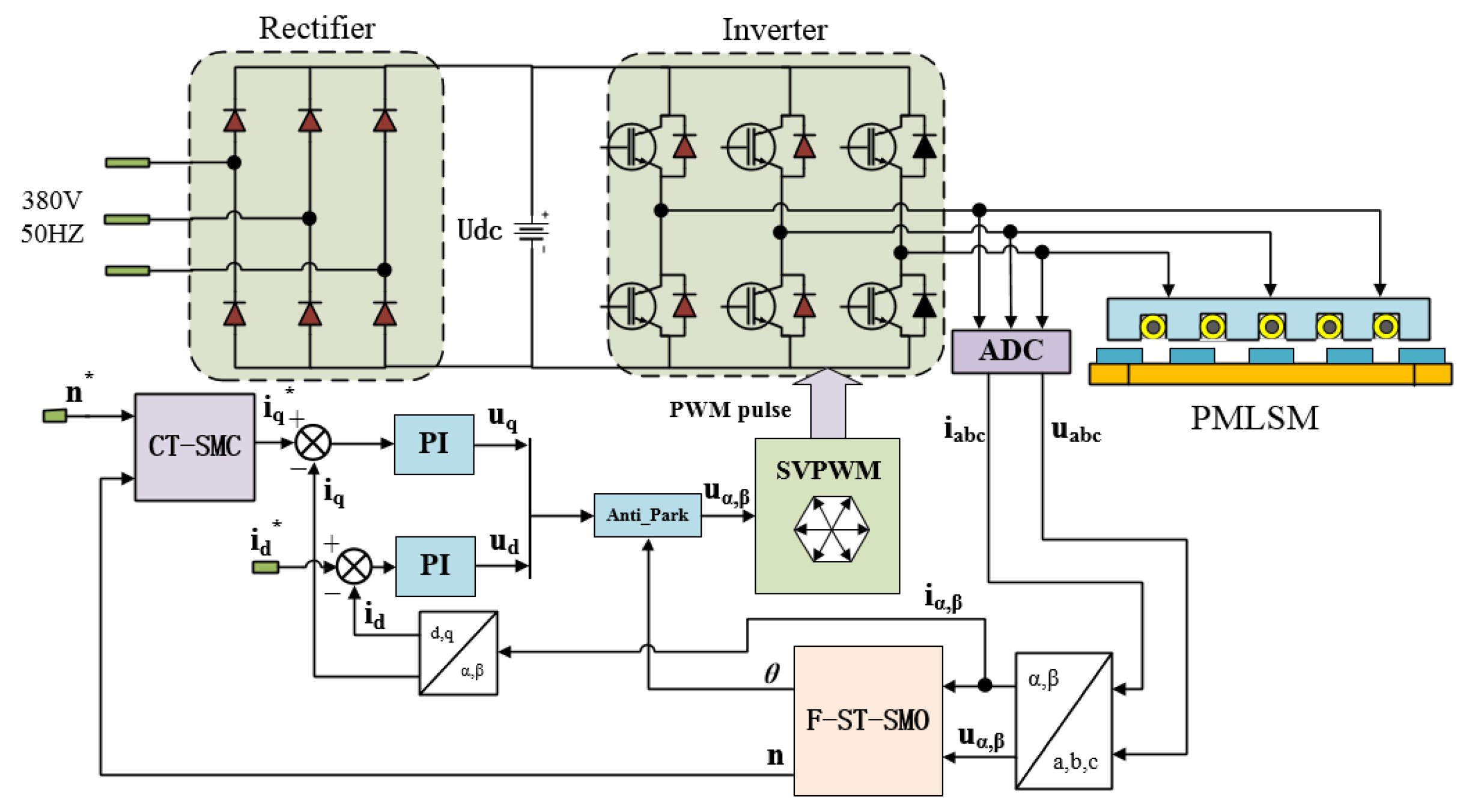
Based on the theoretical basis of SMC and taking PMLSM as the control object, a control system combining CT-SMC and F-ST-SMO is designed.
(2)
To solve the problem of the large error of traditional SMO observations, a hyperdistortion algorithm is introduced to maintain the continuity of output to weaken chattering caused by high-frequency switching in sliding mode. Fuzzy rules are introduced to dynamically adjust the sliding mode gain coefficient to reduce chattering near the sliding mode surface.
(3)
System verification. The dynamic performance of the designed control system is verified by comparing the CTSMC control system with a traditional SMC and PI control system. The observation performance of F-ST-SMO is compared with that of traditional SMO, and the error analysis is made with the data of the mechanical sensor.

2. Design of Terminal Sliding Mode Speed Controller

2.1. PMLSM Mathematical Model

The mathematical model for establishing the PMLSM in the synchronous rotating coordinate system dq is as follows:
{ d i d d t = R s L d i d + π L q τ L d ν i q + u d L d d i q d t = R s L q i q π L d τ L q ν i d + u q L q π ψ f τ L q ν
where R s is the stator resistance; τ is the PMLSM pole pitch; ν is the speed of the linear motor; u d and u q are the voltage of the d q axis; i d and i q are the current of the d q axis; L d and L q are the inductance components of the d q axis; ψ f is the permanent magnet flux linkage.
Since L d = L q in the PMLSM used, the thrust equation can be written as
F e m = p n 3 π 2 τ ψ f i q
where F e m is the thrust of the linear motor, and p n is the number of pole pairs of the linear motor.
The mechanical motion equation of PMLSM is as follows:
m d ν d t = F e m f B ν
where m is the quality of the mover, B is the viscous friction factor, and f is the system disturbance. Simultaneously, formulas (2) and (3) can be obtained
d ν d t = a M i q + b M ν + c M f
where a M = 1 m p n 3 π 2 τ ψ f ; b M = B m ; c M = 1 m .

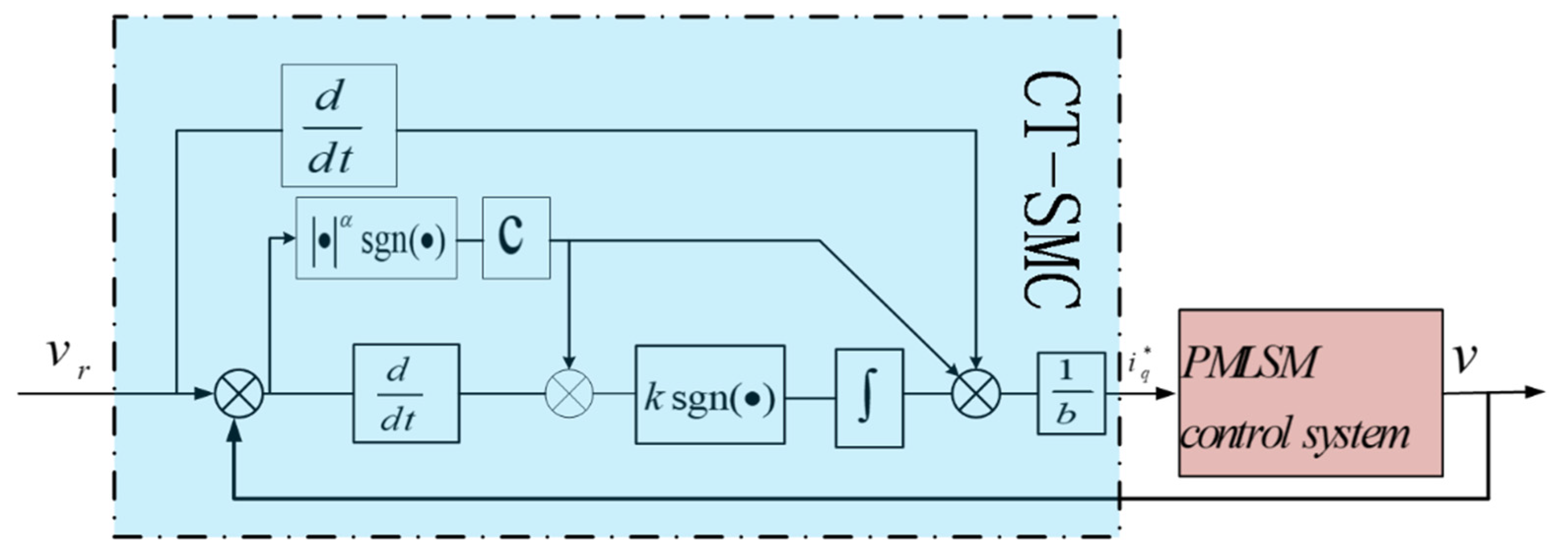
2.2. Design of CT-SMC

The velocity loop controller is designed using a first-order CT-SMC algorithm. From the linear motor equation of motion, the first-order velocity differential equation can be written as
v ˙ = a M i q + b M ν + c M f = a M i q * + b M ν + c M f a M ( i q * i q ) = b i q * + d
where
{ b = a M = 1 m p n 3 π 2 τ ψ f d = b M v + c M f a M ( i q * i q )
d can be regarded as the lumped disturbance of the system. The derivative of d in the system is bounded and satisfies the following conditions:
| d ˙ | k e d
where k e d is an ordinary constant and k e d > 0 .
Let v r be the specified speed of the system, then the speed tracking error is defined as:
e = v r v
Calculate the first derivative of the velocity tracking error, and substitute Equation (5), it can be deduced that
e ˙ = v r ˙ v ˙ = v r ˙ b i q * d
Terminal sliding surface for design is as follows:
s = e ˙ + c sgn ( e ) | e | p / q
where c > 0 , 0 < p / q < 1 .
The speed control law based on CT-SMC is designed as follows:
{ i q * = b 1 ( u e q + u v ) u e q = v r ˙ + c sgn ( e ) | e | α u v = k v 0 t sgn ( s ) d t
where k v is an ordinary constant and k v > 0 , t is the running time of the system α ( 0 , 1 ) ; sgn ( ? ) is a symbolic function; b = a M = 1 m p n 3 π 2 τ ψ f is the control gain. u e q and u v are equivalent control laws.

2.3. Stability Proof of CT-SMC

If system (5) satisfies k v > k e d , under the action of the control law (10), the velocity error of the system will converge to the equilibrium point within a finite time.
Proof. 
According to Equation (9), the sliding surface (10) can be written in the following form:
s = e ˙ + c sgn ( e ) | e | p / q = v r ˙ b i q * d + c sgn ( e ) | e | p / q
Substituting formula (11) into (12), we can obtain:
s = v r ˙ b i q * d + c sgn ( e ) | e | p / q = c sgn ( e ) | e | p / q + v r ˙ ( u e q + u v ) d = c sgn ( e ) | e | p / q + v r ˙ ( v r ˙ + c sgn ( e ) | e | p / q + u v ) d = u v d
The Lyapunov function is used to judge the stability of CT-SMC, and the constructed function is
V = 1 2 s 2
Taking the first derivative of it and substituting it into Equation (13), we can obtain
V ˙ = s s ˙ = s [ u ˙ v d ˙ ]
Substituting Equation (11) into the above equation, we can obtain
V ˙ = s ( u ˙ v d ˙ ) = s ( k v sgn ( s ) d ˙ ) = k v | s | d ˙ s
Formula (16) can be written in the following form:
V ˙ = k v | s | d ˙ s k v | s | + | d ˙ | | s | = [ k v | d ˙ | ] | s | [ k v k c d ] | s | = 2 ( k v k e d ) V 1 2
According to Equation (17), if k v > k e d it is true. Then, V ˙ < 0 is established. It shows that the velocity error will reach the sliding surface s = 0 in a limited time. In this way, there can be a first-order nonlinear differential equation with finite time convergence: s = e ˙ + c sgn ( e ) | e | α = 0 .
When c > 0 , the velocity deviation will converge to the equilibrium state in a finite time along the sliding mode surface s = 0 .
When the fractional power is reduced to integer power 1, the sliding surface in this paper is reduced to:
s = e ˙ + c e
The controller degenerates to:
{ i q * = b 1 ( u e q + u v ) u e q = v ˙ r + c e u v = k v 0 t sgn ( s ) d t
According to the above design, the control structure based on the CT-SMC method can be drawn as shown in Figure 1. The red PMLSM module represents the current closed-loop structure including the permanent magnet synchronous linear motor and other components in Figure 1. □

3. Design of F-ST-SMO

3.1. Traditional SMO

The electrical equation of PMLSM in the α β coordinate system is as follows:
{ d i α d t = 1 L ( R i α + u α E α ) d i β d t = 1 L ( R i β + u β E β )
where E α = π τ v ψ f sin θ   ,   E β = π τ v ψ f cos θ can be regarded as α β induced electromotive force in coordinate system. To acquire the extended back EMF of the estimated value, the SMO can be designed as
{ d i ^ α d t = 1 L ( R i ^ α + u α z α ) d i ^ β d t = 1 L ( R i ^ β + u β z β )
{ z α = k sgn ( i ^ α i α ) z β = k sgn ( i ^ β i β )
where i ^ a , i ^ β is the observed value of current; k is the traditional SMO gain.
Subtracting from Equations (20) and (21), the current error state equation is
{ d i ˜ α d t = 1 L ( R i ˜ α z α + E α ) d i ˜ β d t = 1 L ( R i ˜ β z β + E β )
where i ˜ a = i ^ a i a , i ˜ β = i ^ β i β is the current observation deviation.
SMO is used to estimate the current, and its sliding mode surface function is as follows
i ˜ = [ i ˜ a i ˜ β ] T = 0
SMO enters sliding mode when the following conditions are met
i ˜ T i ˜ ˙ < 0
When the sliding mode gain satisfies Equation (25), then
i ˜ = i ˜ ˙ = 0
Substituting Equation (26) into Equation (23), we can obtain
E = [ k sgn ( i ^ a i a ) k sgn ( i ^ β i β ) ] T
According to Equation (27), it is known that the back EMF estimation is associated with the high frequency switching signal. However, the estimation method based on the arc tangent function directly substitutes the high-frequency switching signal into the division operation of the arc tangent function, resulting in the phenomenon of high-frequency chattering.

3.2. Super-Twisted Control Algorithm

For the traditional first-order sliding mode observer, the estimated back EMF has a chattering phenomenon due to the influence of the sign function, which leads to a tracking error in the estimated mover velocity. Although the chattering can be reduced by low-pass filtering, it will cause a phase delay. To this end, an ST algorithm is introduced to solve the chattering phenomenon caused by the traditional SMO.
The ST algorithm can be shown in formula (28):
{ d x d t = k * | x ˜ | 1 2 sgn ( x ˜ ) + x m d x m d t = k * sgn ( x ˜ )
where x is the state variable, x ˜ is the deviation between the approximated value and the true value, x m is a custom intermediate variable, k * is the ST sliding mode gain.
The state variable x in the ST algorithm is replaced by the current signal i ^ a and i ^ β estimated by PMLSM, and the SMO of PMLSM based on the ST algorithm is obtained, as shown in Equation (29).
{ d i ^ α d t = 1 L ( R i ^ α + u a k f | i ˜ α | 1 2 sgn ( i ˜ α ) k s k f sgn ( i ˜ α ) d t ) d i ^ β d t = 1 L ( R i ^ β + u β k f | i ˜ β | 1 2 sgn ( i ˜ β ) k s k f sgn ( i ˜ β ) d t )
where k f is the boundary function, and k s is a small constant, which is used to reduce the influence caused by the error differential of fuzzy control input.
The current deviation equation acquired by subtracting Equation (20) from Equation (29) is:
{ d i ˜ α d t = 1 L ( R i ˜ α k f | i ˜ α | 1 2 sgn ( i ˜ α ) k s k f sgn ( i ˜ α ) d t + E α ) d i ˜ β d t = 1 L ( R i ˜ β k f | i ˜ β | 1 2 sgn ( i ˜ β ) k s k f sgn ( i ˜ β ) d t + E β )
where i ˜ a = i ^ a i a , i ˜ β = i ^ β i β is the deviation of current observation.
When ST-SMO is stable, the estimated value is equal to the actual value, that is, the PMLSM current estimation error and change rate are approximately zero ( i ˜ α β = i ˜ ˙ α β = 0 ). At this point, the back EMF of the PMLSM estimated by the ST-SMO can be obtained:
{ E a = k f | i ˜ α | 1 2 sgn ( i ˜ α ) + k s k f sgn ( i ˜ α ) d t E β = k f | i ˜ β | 1 2 sgn ( i ˜ β ) + k s k f sgn ( i ˜ β ) d t
In order to improve the chattering problem in SMC, the ST control algorithm is selected to ensure the continuity of the output. The algorithm can weaken the chattering caused by the first-order sliding mode control and improve the dynamic response and anti-interference ability of the system. However, the ST control algorithm relies too much on the upper bound of the boundary function, which is hard to obtain in practice. In addition to the serious influence of the sign function on the buffeting phenomenon of a sliding mode observer, there is also sliding mode gain. In a general sliding mode system, in order to maintain the rapid response ability of the system, a larger sliding mode gain is usually selected, but this will also produce a larger buffeting. When the moving point is close to the sliding mode surface, a small gain is enough. Therefore, if the sliding mode gain can be adjusted adaptively according to the position of the moving point relative to the sliding mode surface, the buffeting of the system can be effectively suppressed. In order to realize the adaptive adjustment of the sliding mode gain, a fuzzy control rule is introduced.

3.3. Design of Fuzzy Controller

Fuzzy control has strong adaptability to external disturbances because it does not completely rely on mathematical models, but on fuzzy rules. It is especially suitable for nonlinear control systems.
The boundary function k f is estimated according to the sliding mode reachable condition. The input variables of the fuzzy control system are i ˜ a β and i ˜ ˙ a β , and the output variable is k f . If i ˜ a β is large, it indicates that there is a large difference between i ^ a β and i a β , and the moving point is far from the sliding mode surface, and then k f should increase. If i ˜ a β is small, it means that the motion point is close to the sliding surface, and then k f should decrease. If i ˜ ˙ a β is large, it indicates that the moving point is rapidly moving away from or close to the sliding mode surface, and the gain needs to be increased to strengthen the control effect; otherwise, the gain needs to be reduced.
The input variables are defined in the domain of {−0.002 0.002}, and the output variables in the domain of {1000 1400}. The input of fuzzy language is {NB (negative big), NS (negative small), Z(zero), PS (positive small), PB (positive big)}, and the fuzzy language value of the output is {PS (positive small), S(small), M(medium), B(big), PB (positive big)}. Control rules obtained by designing k f are shown in Table 1.

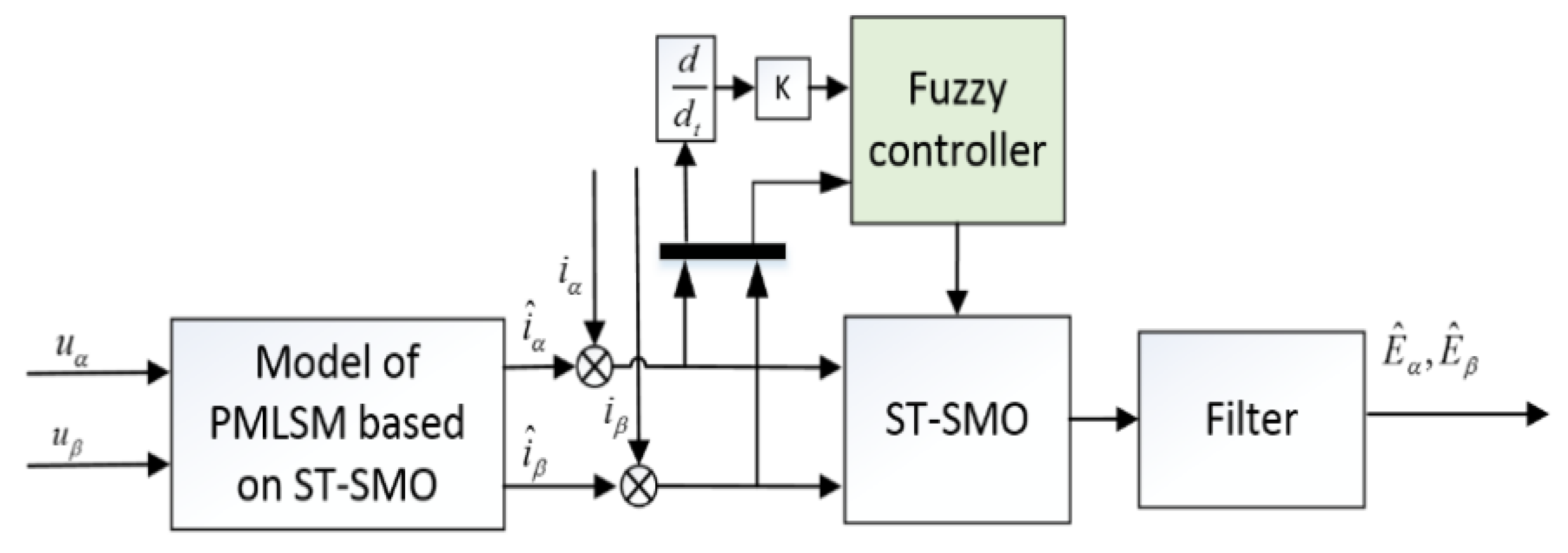
3.4. Construction of F-ST-SMO Model

Based on the current model of the PMLSM in the α β coordinate system, such as formula (32):
i ˙ α β = 1 L ( R i α β + u α β E α β )
where i α β = [ i α   i β ] T is the stator α β axis current; R is stator resistance; L is the stator inductance; u α β = [ u α   u β ] T is the voltage of stator α β axis; E α β = [ E α   E β ] T is the inverse electromotive force of the linear electric motor. PMLSM current equation based on F-ST-SMO can be restated as:
i ^ ˙ α β = 1 L ( R i ^ α β + u α β z α β )
where i ^ α β = [ i ^ α   i ^ β ] T is the estimation of stator α β axis current; z α β = k f | i ˜ α β | 1 2 sgn ( i ˜ α β ) + k s k f sgn ( i ˜ α β ) d t is the control law. Where k f is the boundary function, k f is derived from fuzzy control rules. The main task of the observer is to select a suitable control law to minimize the estimation error and finally estimate the motor stator α β axis back EMF. When the sliding mode switching function approaches the sliding mode switching surface, i ˜ α β = i ˜ ˙ α β = 0 is obtained, and Equation (31) is obtained. To obtain a continuous estimate of the back EMF, a low-pass filter is required, as shown in the equation:
E ^ α β = ω c s + ω c z α β
where w c = 2 π f c ,   f c indicates the cut-off frequency of the low-pass filter.
To obtain the velocity information of the mover, the estimated value of velocity is expressed as:
ω ^ e = E α 2 + E β 2 ψ f
where w ^ e = π τ v ^ , and we can finally obtain an estimate of the velocity of the actuator.
To sum up, the control principle of F-ST-SMO is to first use the input voltage signal through the sliding mode observer designed by the PMLSM current state equation to obtain the current estimated value of the SMO, and then compare it with the actual PMLSM current signal. The error and rate of change of the current signal are obtained by making the difference, the control gain of the sliding mode observer is dynamically regulated through the fuzzy control rules, the estimated back EMF is obtained through the ST algorithm, and finally the mover speed is obtained. The principle of the F-ST-SMO is shown in Figure 2.

4. Simulation and Experimental Results

4.1. Comparison of Speed Controllers

The block diagram of the PMLSM control system designed in this paper is set up in MATLAB/SIMULINK, as shown in Figure 3. The motor driving parameters used are shown in Table 2, and the improved SMC is compared with the traditional PI and traditional SMC control system.

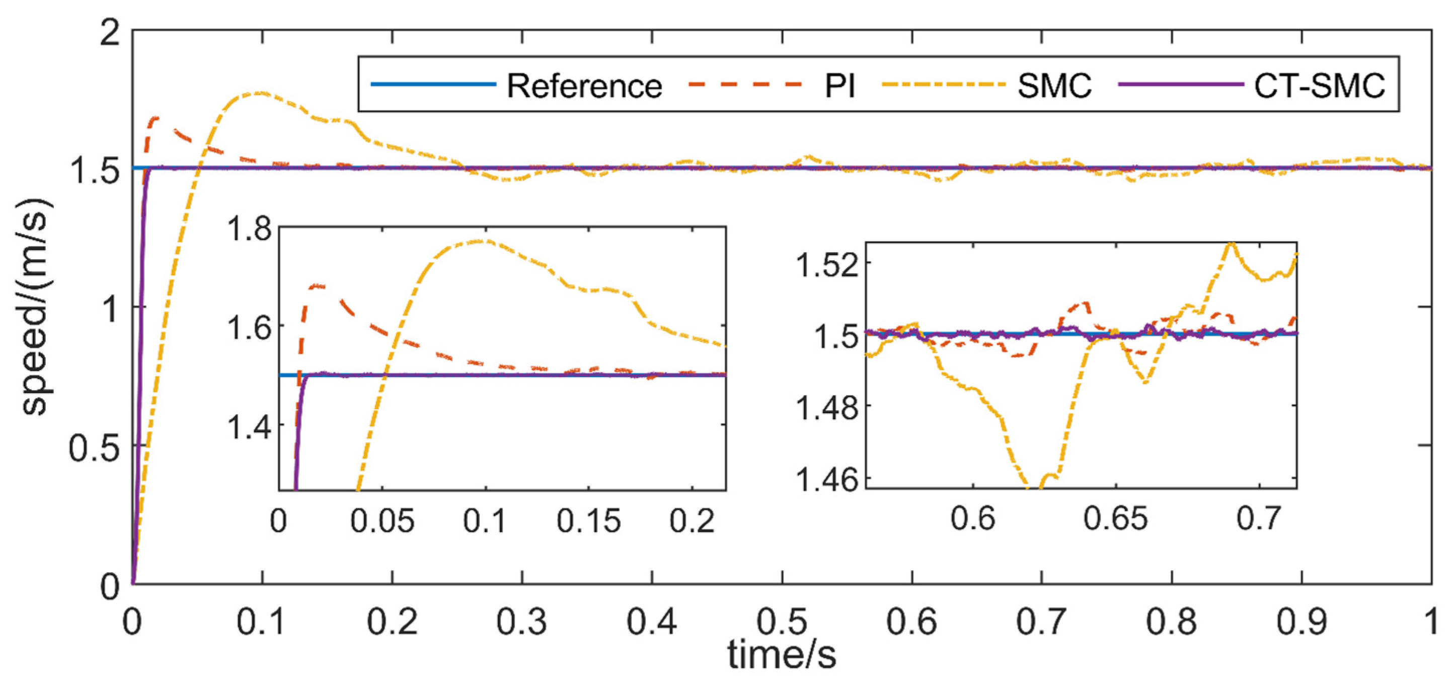
4.1.1. Constant Load, Varying Speed

To analyze the dynamic response performance of the designed control system, the traditional PI control and traditional SMC are set up as a comparison. The speed change of the given system is ( 1 m / s 2 m / s 3 m / s ) to observe the tracking effect of PMLSM for different speeds and the dynamic response performance when the speed changes. Figure 4 shows the comparison of the operation speed of the CT-SMC system, traditional PI control system and SMC system.
To analyze the speed contrast diagram, the CT-SMC system shown in this paper has almost no overshoot in the process from 0 to 1 m/s and from 1 to 2 m/s. Although there is overshoot in the process from 2 to 3 m/s, the overshoot is much smaller than that in the traditional PI control and traditional SMC system. In these three speed increases, the process from 2 to 3 m/s is the worst dynamic response time of CT-SMC designed in this paper. The CT-SMC system still shows superior control performance versus the traditional control. In the process of speed change, the adjustment time of CT-SMC is less than 0.05 s, the adjustment time of PI is more than 0.1 s, while the adjustment time of conventional SMC is more than 0.2 s.
Figure 5 shows the thrust variation comparison of the three control systems. Among the three control modes, it can be seen that the SMO system shows strong thrust fluctuation due to its inherent characteristics. The CT-SMC system designed in this paper has a similar trend of thrust change with the traditional PI control system, but when the speed changes, the thrust changes significantly, resulting in a long overshoot time.

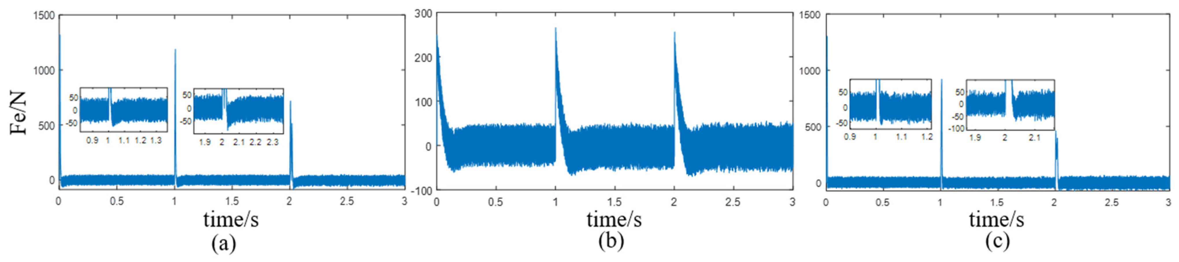
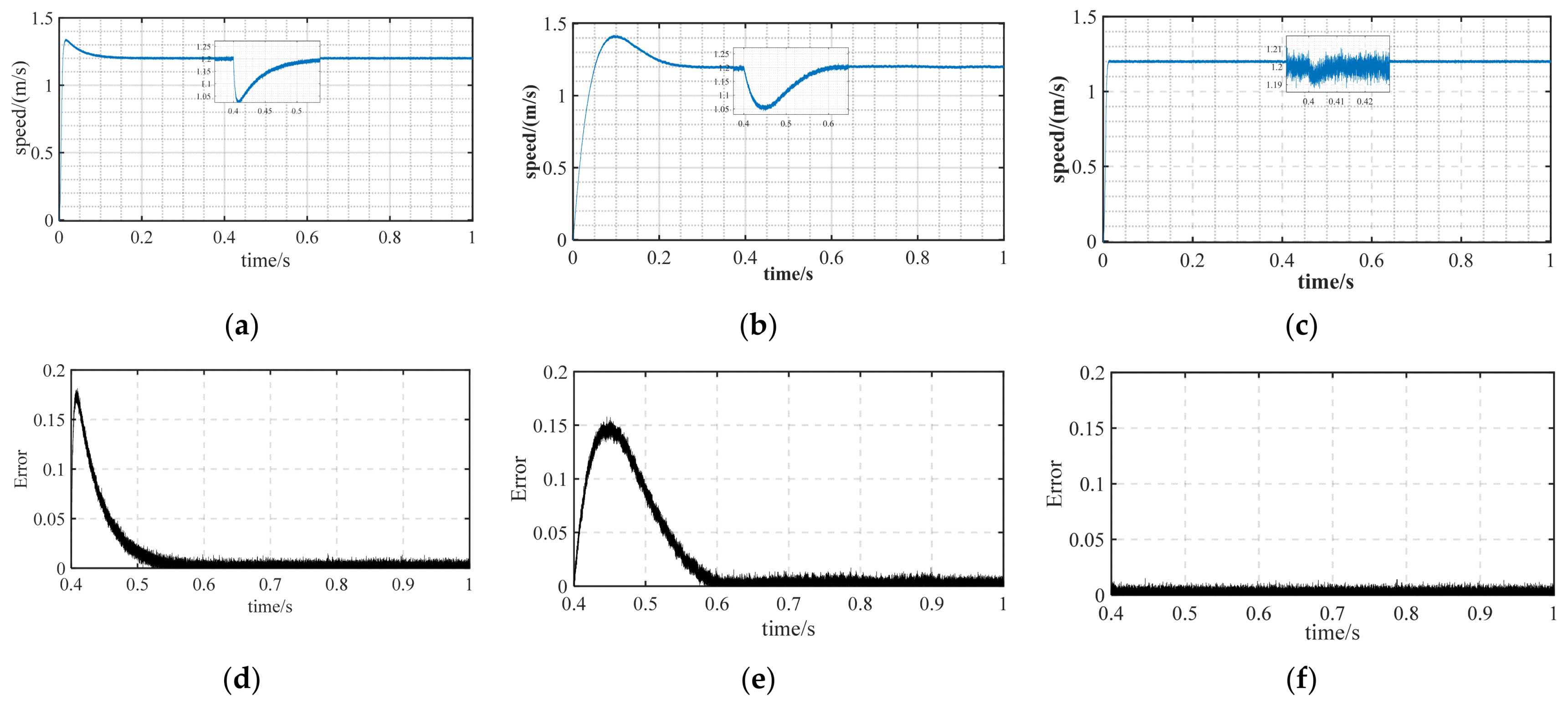
4.1.2. Constant Speed, Varying Load

Given that the system speed is 1.5 m/s, and the running time is set as 1 s, random load is added into the control system as shown in Figure 6. Figure 7 shows the comparison of the running speed of the three systems. The overshoot and overshoot time of the CT-SMC control system are much less than those of the other two control systems.

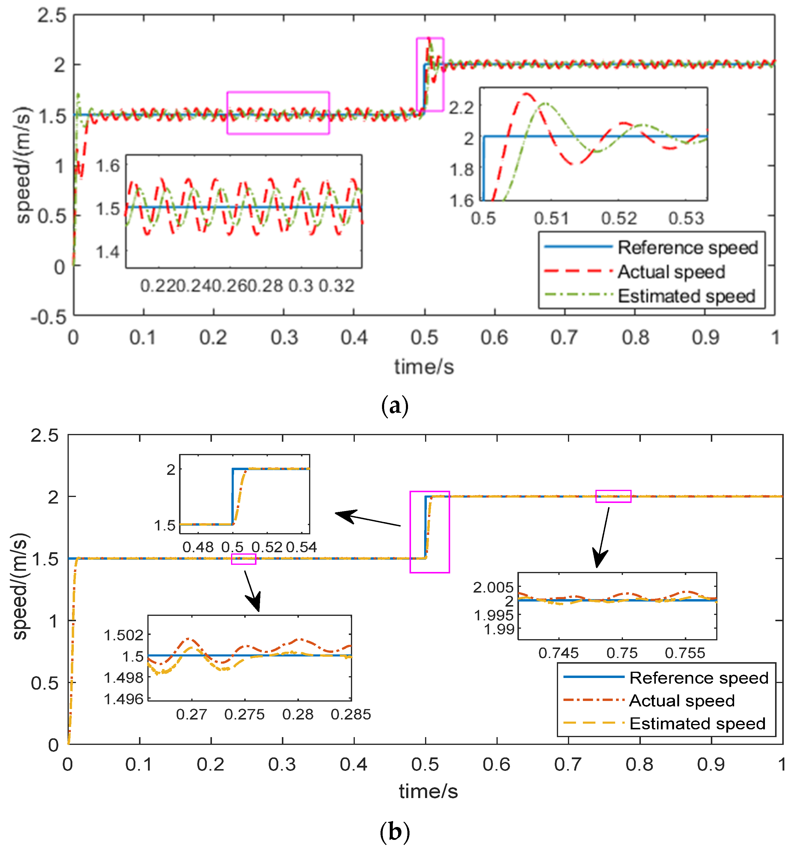
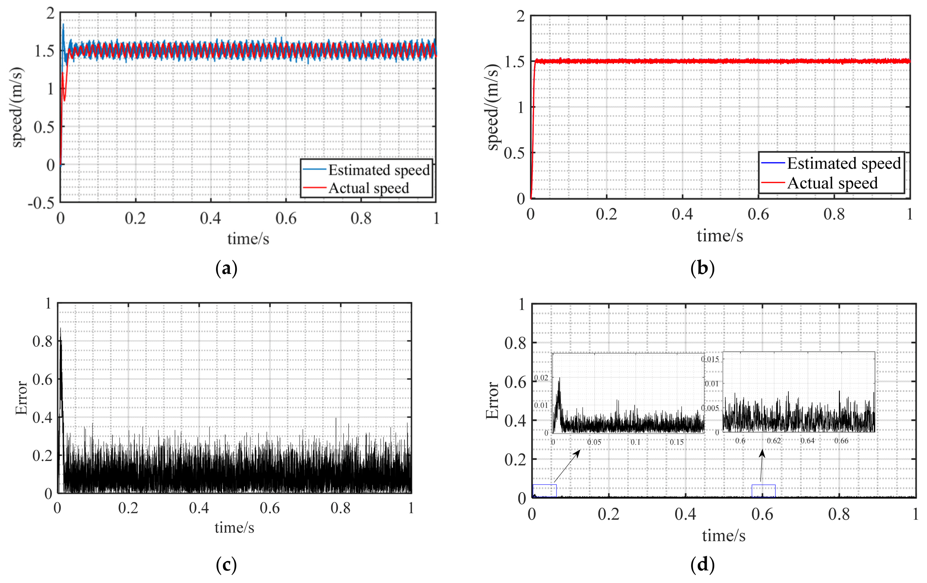
4.1.3. Observer Comparison
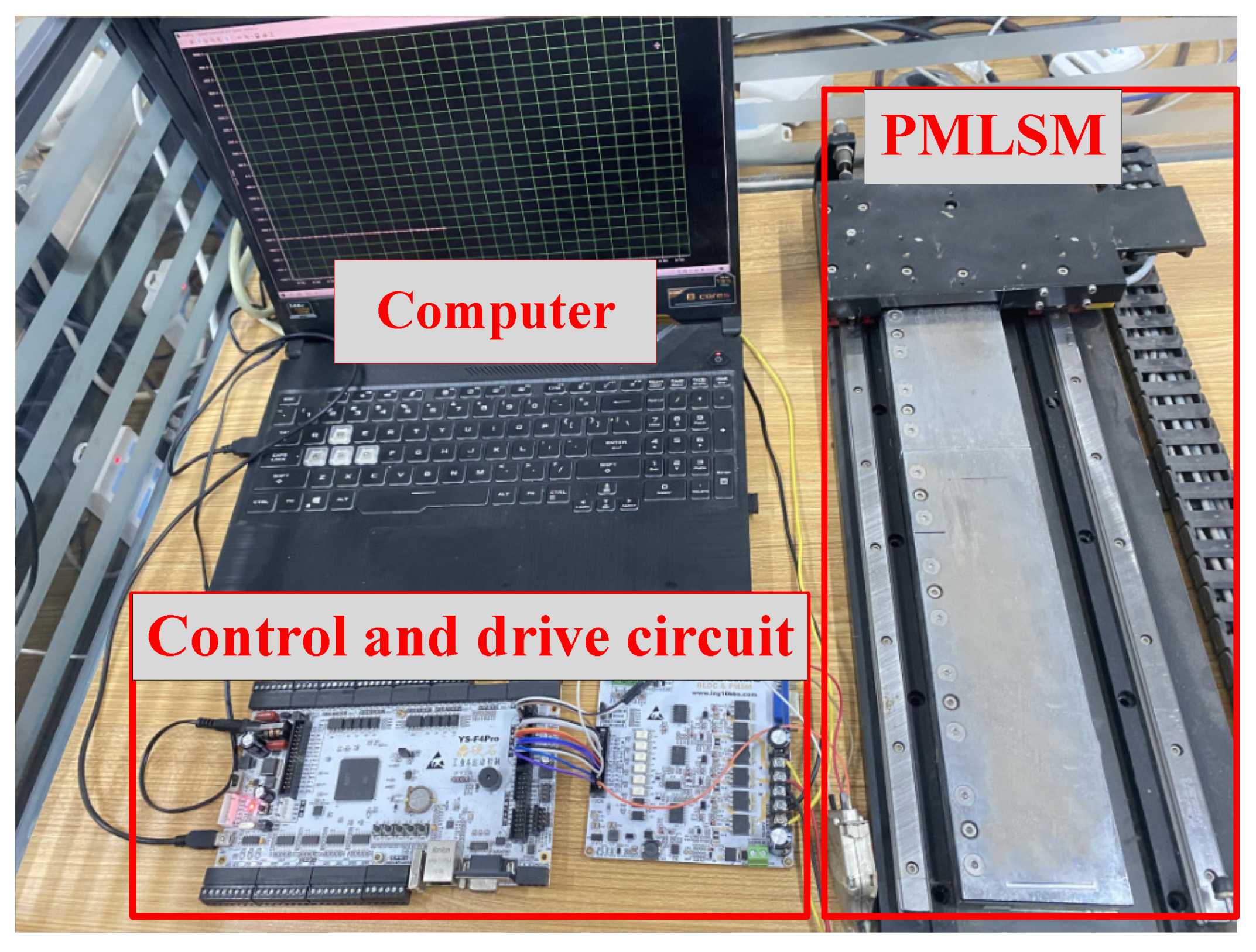
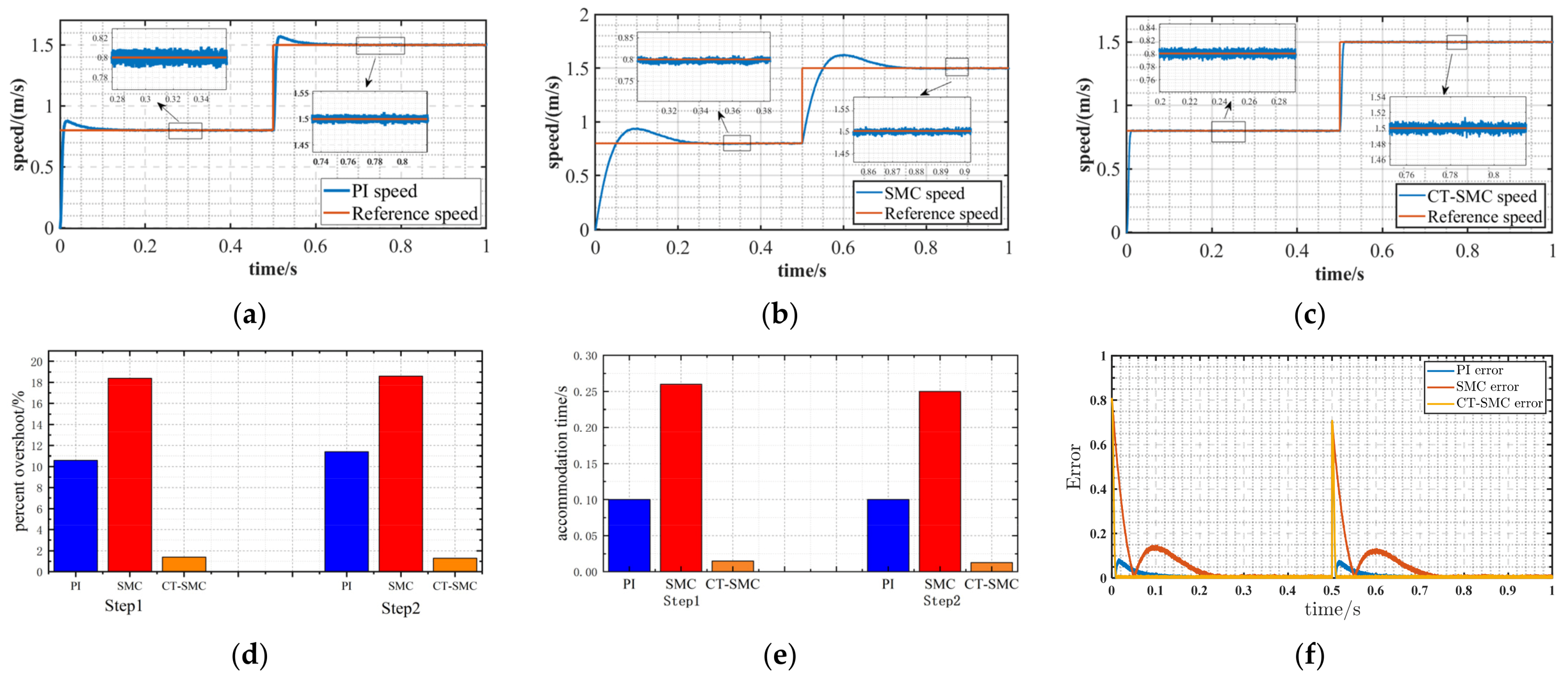
Through the simulation verification, the superior control performance of the CT-SMC system designed in this paper is proven. On the basis of the CT-SMC system, the traditional SMO is added to compare with the designed F-ST-SMO. The speed of the given system is 1.5 m/s, and the speed rises to 2 m/s at 1 s, so as to analyze the tracking situation and dynamic response ability of the observer at different speeds.
It can be seen from Figure 8 that the traditional SMO observation speed will have large chattering, and the observer directly gives the error caused by chattering to the speed controller of the control system, resulting in a decrease in the overall accuracy of the control system. In the simulation diagram, the medium tracking speed fluctuates around the reference speed. In the F-ST-SMO system designed in this paper, due to the action of the fuzzy controller, the output changes to the sliding mode gain, which validly reduces the buffeting of the traditional SMO and has higher accuracy.

4.2. Experiment

Compared with the simulation environment, the experimental environment has more external disturbances, and there is a heating phenomenon in the operation of the electrical generator. Building an experimental platform for verification is conducive to further improving the control system, such that the designed algorithm can be better and faster applied in practical applications. The experimental platform as shown in Figure 9 is built in this paper, which is mainly composed of upper computer, servo driver, control card, grating sensor and precision linear motor. The on–off controlled electromagnetic weight is used as the load of the linear motor. During the operation of the linear motor, the sensor transmits the position signal and current signal to the control board for closed-loop control operation. The encoder is used to compare with the observer designed in this paper. The motor parameters selected in this paper are shown in Table 2.
First, the proposed CT-SMC control system is built and compared with the traditional PI control system, and then the traditional SMC control system, the dynamic performance, and anti-disturbance performance of the controller are analyzed. The given speed of the system was set as 0.8–1.5 m/s. Figure 10 shows the dynamic effect under three control strategies. Figure 10a–c shows the comparison diagrams of the running speed and reference speed of the PI control system, SMC control system and CT-SMC control system, respectively. Figure 10d–f shows the comparison of overshoot, regulation time and error of the three control systems. It can be concluded from the analysis that the traditional SMC control system has more room for improvement compared with the current more mature PI control system. It has a larger overshoot and longer adjustment time. Through the improved CT-SMC, the overshoot and adjustment time are greatly reduced, and the error is also smaller.
Figure 11 shows the operation of the three control systems at a given speed of 1.2 m/s and with a 50 N load added at 0.4 s. Figure 11a–c shows the operating speed waveforms of the three control systems, and Figure 11d–f shows the speed errors of the three control systems after loading. According to the analysis, when the load was added, the fluctuation of the SMC control system decreased slightly compared with PI, but there was still a large fluctuation. The improved CT-SMC control system not only has good dynamic performance, but also has good anti-disturbance performance.
CT-SMC can have a good control effect in dynamic response and anti-disturbance performance. On the basis of selecting CT-SMC for the controller, traditional SMO and F-ST-SMO are added for speed observation. Figure 12 is the speed operation when the given system speed is 1.5 m, and the observed speed of the observer is fed back to the speed controller. Mechanical sensors are used for comparison with estimated speed. The traditional SMO has a large jitter and a large distortion in the speed-up stage, and the speed also has a large jitter after the speed reaches the reference speed. In the speed observation of F-ST-SMO, the observed speed is close to the real speed in both thethe speed rising stage and the speed stable operation stage. Compared with the traditional SMO, the F-ST-SMO is much smaller than the traditional SMO.
The experimental results show that the F-ST-SMO sensorless control system based on CT-SMO performs well in dynamic performance and anti-disturbance performance. The sensorless control system simplifies the mechanical structure of the control system and greatly improves the control accuracy compared with the traditional SMO.

5. Conclusions

In this paper, a CT-SMC and F-ST-SMO control system based on the PMLSM mathematical model is proposed. This method provides a solution for high-precision operation of a PMLSM sensorless system. The mechanical motion equations of PMLSM are analyzed, and a speed closed-loop controller is designed using a continuous terminal sliding mode control algorithm. The voltage equation of PMLSM was rewritten in the static coordinate system, and F-ST-SMO was designed to replace the traditional mechanical sensor. The simulation and experimental verification of the designed control system under variable speed and load conditions show that the dynamic performance of the designed control system is better, and the position tracking error is greatly reduced.

Author Contributions

Writing—review and editing, supervision, project administration, funding acquisition, Z.L.; writing—review and editing, supervision, project administration, funding acquisition, H.S. (Z.L. and H.S. contributed equally to this work as corresponding authors); methodology, software, writing—original draft preparation, J.W. and S.W.; validation, S.F. and Y.Z. All authors have read and agreed to the published version of the manuscript.

Funding

This work is supported by the National Natural Science Foundation of China (no. 51877070, U20A20198, 51577048), the Natural Science Foundation of Hebei Province of China (no. E2021208008), the Talent Engineering Training Support Project of Hebei Province (A201905008), the National Engineering Laboratory of Energy-saving Motor and Control Technique, Anhui University (no. KFKT201901).

Conflicts of Interest

The authors declare no conflict of interest.

References

  1. Liu, J.-L.; Xiao, F.; Shen, Y.; Mai, Z.-Q.; Li, C.-R. Position-sensorless control technology of permanent-magnet synchronous motor—A review. Trans. China Electrotech. Soc. 2017, 32, 76–88. [Google Scholar]
  2. Yang, C.; Ma, T.; Che, Z.; Zhou, L. An adaptive-gain sliding mode observer for sensorless control of permanent magnet linear synchronous motors. IEEE Access 2018, 6, 3469–3478. [Google Scholar] [CrossRef]
  3. Ding, B.; Xu, D.; Jiang, B.; Shi, P.; Yang, W. Disturbance-observer-based terminal sliding mode control for linear traction system with prescribed performance. IEEE Trans. Transp. Electrif. 2021, 7, 649–658. [Google Scholar] [CrossRef]
  4. Zhao, X.; Fu, D. Adaptive neural network nonsingular fast terminal sliding mode control for permanent magnet linear synchronous motor. IEEE Access 2019, 7, 180361–180372. [Google Scholar] [CrossRef]
  5. Roy, S.; Baldi, S.; Fridman, L.M. On adaptive sliding mode control without a priori bounded uncertainty. Automatica 2020, 111, 108650. [Google Scholar] [CrossRef]
  6. Cheema, M.A.M.; Fletcher, J.E.; Farshadnia, M.; Rahman, M.F. Sliding mode based combined speed and direct thrust force control of linear permanent magnet synchronous motors with first-order plus integral sliding condition. IEEE Trans. Power Electron. 2019, 34, 2526–2538. [Google Scholar] [CrossRef]
  7. Wang, W.; Lin, H.; Yang, H.; Liu, W.; Lyu, S. Second-order sliding mode-based direct torque control of variable-flux memory machine. IEEE Access 2020, 8, 34981–34992. [Google Scholar] [CrossRef]
  8. Sun, X.; Cao, J.; Lei, G.; Guo, Y.; Zhu, J. A composite sliding mode control for SPMSM drives based on a new hybrid reaching law with disturbance compensation. IEEE Trans. Transp. Electrif. 2021, 7, 1427–1436. [Google Scholar] [CrossRef]
  9. Jin, H.; Zhao, X. Approach angle-based saturation function of modified complementary sliding mode control for PMLSM. IEEE Access 2019, 7, 126014–126024. [Google Scholar] [CrossRef]
  10. Cheema, M.A.M.; Fletcher, J.E.; Farshadnia, M.; Xiao, D.; Rahman, M.F. Combined speed and direct thrust force control of linear permanent-magnet synchronous motors with sensorless speed estimation using a sliding-mode control with integral action. IEEE Trans. Ind. Electron. 2017, 64, 3489–3501. [Google Scholar] [CrossRef]
  11. Yang, R.; Li, L.-Y.; Wang, M.-Y.; Zhang, C.-M.; Zeng-Gu, Y.-M. Force ripple estimation and compensation of PMLSM with incremental extended state modeling-based kalman filter: A practical tuning method. IEEE Access 2019, 7, 108331–108342. [Google Scholar] [CrossRef]
  12. Wen, T.; Wang, Z.; Xiang, B.; Han, B.; Li, H. Sensorless Control of Segmented PMLSM for Long-Distance Auto-Transportation System Based on Parameter Calibration. IEEE Access 2020, 8, 102467–102476. [Google Scholar] [CrossRef]
  13. Wang, A.; Jia, X.; Dong, S. A new exponential reaching law of sliding mode control to improve performance of permanent magnet synchronous motor. IEEE Trans. Magn. 2013, 49, 2409–2412. [Google Scholar] [CrossRef]
  14. Wang, Y.; Feng, Y.; Zhang, X.; Liang, J. A new reaching law for antidisturbance sliding-mode control of PMSM speed regulation system. IEEE Trans. Power Electron. 2020, 35, 4117–4126. [Google Scholar] [CrossRef]
  15. Roy, S.; Baldi, S.; Ioannou, P.A. An Adaptive Control Framework for Underactuated Switched Euler-Lagrange Systems. IEEE Trans. Autom. Control 2021. [Google Scholar] [CrossRef]
  16. Xu, Z.; Rahman, M.F. Comparison of a sliding observer and a kalman filter for direct-torque-controlled IPM synchronous motor drives. IEEE Trans. Ind. Electron. 2012, 59, 4179–4188. [Google Scholar] [CrossRef]
  17. Cao, R.; Jiang, N.; Lu, M. Sensorless control of linear flux-switching permanent magnet motor based on extended kalman filter. IEEE Trans. Ind. Electron. 2020, 67, 5971–5979. [Google Scholar] [CrossRef]
  18. Zhou, Z.; Xia, C.; Yan, Y.; Wang, Z.; Shi, T. Disturbances attenuation of permanent magnet synchronous motor drives using cascaded predictive-integral-resonant controllers. IEEE Trans. Power Electron. 2018, 33, 1514–1527. [Google Scholar] [CrossRef]
  19. Wen, T.; Liu, Y.; Wu, Q.H.; Qiu, L. Cascaded sliding-mode observer and its applications in output feedback control part I: Observer design and stability analysis. CSEE J. Power Energy Syst. 2021, 7, 295–306. [Google Scholar]
  20. Rsetam, K.; Cao, Z.; Man, Z. Cascaded-extended-state-observer-based sliding-mode control for underactuated flexible joint robot. IEEE Trans. Ind. Electron. 2020, 67, 10822–10832. [Google Scholar] [CrossRef]
Figure 1. System block diagram of PMLSM based on CT-SMC.
Electronics 11 01394 g001
Figure 2. F-ST-SMO algorithm implementation diagram.
Electronics 11 01394 g002
Figure 3. Control system block diagram.
Electronics 11 01394 g003
Figure 4. Speed comparison.
Electronics 11 01394 g004
Figure 5. The thrust comparison of the three control system: (a) thrust change of the CT-SMC system; (b) thrust change of the PI control system; (c) thrust change of the SMC system.
Electronics 11 01394 g005
Figure 6. Random load added to the system.
Electronics 11 01394 g006
Figure 7. Comparison of running speed.
Electronics 11 01394 g007
Figure 8. Comparison of observation effects of observers: (a) waveform of observed velocity and actual velocity of conventional SMO system; (b) waveform of observed velocity and actual velocity of THE F-ST-SMO system.
Electronics 11 01394 g008
Figure 9. Experimental platform.
Electronics 11 01394 g009
Figure 10. Dynamic performance comparison of the three control effects: (a) speed of PI control system; (b) speed of SMC control system; (c) speed of CT-SMC control system; (d) overshoot comparison of the three control systems; (e) adjustment time comparison of the three control systems; (f) error comparison of the three control systems.
Electronics 11 01394 g010
Figure 11. Under the three control strategies, the operation condition with load added at 0.4 s: (a) speed of PI control system; (b) speed of SMC control system; (c) speed of CT-SMC control system; (d) speed error of PI control system after 0.4 s; (e) speed error of SMC control system after 0.4 s; (f) speed error of CT-SMC control system after 0.4 s.
Electronics 11 01394 g011
Figure 12. Comparison of the operation of the two observers; (a) comparison between the observation speed and the actual speed of conventional SMO; (b) comparison between the observation speed and the actual speed of F-ST-SMO; (c) observation error of conventional SMO; (d) observation error of F-ST-SMO.
Electronics 11 01394 g012
Table 1. Control rules.
i ˜ α β i ˜ ˙ α β
NBNSZOPSPB
NBPBPBBBM
NSPBBBMM
ZOBMMSS
PSSMMBB
PBMBBPBPB
Table 2. Main parameters of straight line.
ParameterValue
stator resistance Rs/Ω4.0
d-q axis inductance Ldq/mH8.2
Mover mass m/kg1.425
Viscous friction coefficient B/N/m·s44
Polar distance τ/m0.016
DC Bus Voltage U/V48
Publisher’s Note: MDPI stays neutral with regard to jurisdictional claims in published maps and institutional affiliations.

