Article

Fuel Cell Voltage Regulation Using Dynamic Integral Sliding Mode Control

1
Department of Basic Sciences, Preparatory Year Deanship, King Faisal University, Al Hofuf 31982, Saudi Arabia
2
Department of Electrical Engineering, The University of Lahore, Lahore 54000, Pakistan
*
Author to whom correspondence should be addressed.
Electronics 2022, 11(18), 2922; https://doi.org/10.3390/electronics11182922
Submission received: 3 August 2022 / Revised: 6 September 2022 / Accepted: 11 September 2022 / Published: 15 September 2022
(This article belongs to the Special Issue Sliding Mode Control in Dynamic Systems)

Abstract

:
Fuel cells guarantee ecological ways of electricity production by promising zero emissions. Proton exchange membrane fuel cells (PEMFCs) are considered one of the safest methods, with a low operating temperature and maximum conversion efficiency. In order to harness the full potential of PEMFC, it is imperative to ensure the membrane’s safety through appropriate control strategies. However, most of the strategies focus on fuel economy along with viable fuel cell life, but they do not assure constant output voltage characteristics. A comprehensive design to regulate and boost the output voltages of PEMFC under varying load conditions is addressed with dynamic integral sliding mode control (DISMC) by combining the properties of both the dynamic and integral SMC. The proposed system outperforms in robustness against parametric uncertainties and eliminates the reaching phase along with assured stability. A hardware test rig consisting of a portable PEMFC is connected to the power converter using the proposed technique that regulates voltage for varying loads and power conditions. The results are compared with a proportional integral (PI) based system. Both simulation and hardware results are provided to validate the proposed technique. The experimental results show improvements of 35.4 % , 34 % and 50 % in the rise time, settling time and robustness, respectively.

1. Introduction

Fuel cells (FC) are regarded as ecologically clean electrochemical devices which perform highly efficient energy conversion with almost zero emissions [1,2,3]. They are also merited as renewable energy sources, owing to their use of hydrogen and air as fuel. A FC is constructed with varied configurations among which proton exchange membrane fuel cells (PEMFC) are mostly found in commercial vehicles on account of their vibration resilience, comparatively low operating temperature and noise-suppressing attributes [4,5].
PEMFC operation is inherently nonlinear and varying load conditions affect its maximum efficiency; therefore, various control strategies have been put forward to ensure favorable operating conditions for fuel cells. The appropriate control strategy also warrants an enhanced lifetime of the fuel cell by avoiding fuel starvation within the cell. These approaches have mostly been evaluated with respect to fuel utilization (hydrogen and oxygen), humidity control within the cell, optimal cell operating temperature, fuel pressure, and maximum power point parameters [6,7,8,9,10].
Fuel cell control becomes a challenging problem, especially when dealing with time-delayed systems. An adaptive control technique, extremum seeking (ES), based on the real-time tuning of parameters of nonlinear systems was investigated in [11]. To optimize fuel usage in terms of flow rate, the research community used model predictive control (MPC) due to its robustness against disturbance within defined limits [12,13,14]. The management of temperature stress was also ascribed to feedforward MPC in PEMFC [15]. However, MPC bounds are narrow, and its complex implementation requires more execution time [16]. The oxygen flow rate from air with appropriate pressure in PEMFC was also implemented using fuzzy, proportional integral derivative (PID) controllers or with an amalgam of both fuzzy and PID controllers; possessing the capability of reducing steady state error and oscillations, along with eliminating the need for a precise mathematical model [17,18,19,20]. Although the combination of the two strategies presents a promising outcome, the limitations of fuzzy controller in terms of initial assumptions and need for constant system upgrading do not qualify it as a reliable solution [21]. Variations of the sliding mode control (SMC) approach, such as SMC based on the super twisting algorithm (STA) and second-order SMC implementations, have also been utilized for improving performance in handling fuel starvation, as a consequence of load variations and parametric uncertainties, as well as maximum power point tracking (MPPT) algorithms [22,23]. The authors of [24,25] used a fast track integral SMC for regulating the fuel-excess ratio, and first- and-second order SMC variations of the super twisting algorithm to analyze performance of various PEMFC parameters, respectively.
However, the control strategies mentioned above only promise fuel economy and viable fuel cell life and do not guarantee constant output voltage or current characteristics, thus requiring the integration of the optimal power converter with PEMFC [26]. PEMFC is considered an ideal candidate for electric vehicles (EV); however, its output voltage needs to be boosted to meet the electrical requirements of EVs. In this regard, ref. [27] worked on the cell voltage stability of a fuel cell stack during the aging process under dynamic load conditions. Similarly, ref. [28] provided a comparative analysis of PID and MPC techniques for controlling the dynamics of voltage and temperature of PEMFC, and [29] worked on the modified whale optimization algorithm to achieve a stable voltage curve. An ES technique was utilized by [30] for PEMFC control with respect to constant current and hydrogen influx. State-of-the-art research in the control domain classifies SMC as the best candidate for nonlinear systems with unknown disturbances and load uncertainties, along with the improved transient response [31,32,33]. However, it is only true if implemented through the discontinuous control law, where the switching frequency approaches infinity.
A more accurate approach was discussed in [34,35], where a hysteresis comparator replaced the discontinuous sign function, resulting in a finite switching frequency. The associated drawback is a variable switching frequency that depends on the states of the system [36]. Moreover, the electromagnetic compatibility (EMC) issues resulting through the variable frequency pose additional design challenges [37,38,39]. Therefore, it is necessary to achieve a fixed switching frequency in SMC because power converters are composed of reactive components, and their accurate design is frequency dependent, thereby making it an active area for research [40,41,42]. In this domain, some stimulating work was done by means of equivalent control via filter extraction [42], full bridge converters with phase shifts [43], buck converters with interleaving [39], controlling the current of DC/AC machines [44], cascaded converters [45], and DC power converters [46]. Furthermore, Repecho et al. in [47] provided a technique to fix the frequency in the hysteresis band of the SMC.
One way of fixing the frequency utilizes an adaptive controller, where the width of the hysteresis band is adjusted as proposed in [38,39,42] and [48]. However, information about the plant parameters is needed for a precise design. Using additional sensors for parametric detection adds to the system cost, thereby limiting its utilization. Repecho et al. exploited an external signal for a fixed-rate SMC; however, the addition of new hardware and the underlying condition of requiring the system time constant to be large enough as compared to the switching frequency are its weaknesses.
Another technique, called zero average dynamics (ZAD), was utilized in [49,50], where the goal was to find a duty cycle that corresponds to the zero average value of the dynamics of the selected sliding manifold. This allows the switching rate of the steady state to be configured as desired, resulting in a performance average which is near the ideal behavior. However, the use of the algorithm is limited by the need to perform complex calculations, thereby requiring a powerful real-time processor.
Yet another method which uses the first derivative of the required value corresponding to the switching manifold provides a direct equivalent control implementation, and is mentioned by the researchers in [51,52,53,54]. However, reduced robustness and increased system order are its weaknesses, as the discontinuous function is not implemented directly. Ref. [55] used a smooth second-order SMC for robustness, but it suffers from slow convergence. Moreover, another design to achieve a fixed switching rate is by using pulse-width modulation (PWM), as stated by Abrishamifar et al. [56] and Ye et al. [57]. It provides a trade-off between robustness and chattering as the control law morphs into a limiting layer.
Researchers in [58,59,60] achieved a fixed switching rate in SMC by means of an extra control loop, based on proportional-integral (PI) control, to administer the hysteresis width. It requires slower dynamics of the PI loop to achieve interference-free regulation of the voltage and current, and is hindered by the need for additional calculations for this extra layer of control.
Scientists in [61] utilized the integral sliding-mode controller (ISMC) for converter voltage stability. This technique enforces the sliding mode through the entire response since it eliminates the reaching phase, thereby ensuring robustness from the beginning. In traditional first-order SMC, the robustness of the system is compromised during the reaching phase. The system becomes parametric invariant only when the sliding phase is established. This issue is resolved using integral SMC, where the reaching phase is eliminated, and the system enters the sliding mode from the very initial phase, thus ensuring robustness throughout the control. A double integral SMC was proposed by [62] which provides a constant operational switching frequency with improved robustness and true parametric independence, but it suffers from the higher complexity of implementation.
A dynamic integral SMC for power converters was proposed by [63] which is robust against parametric uncertainties and other perturbations, and the technique itself performs better than ISMC [64]. It eliminates the reaching phase, thereby canceling out the matched disturbances. These control techniques of power converters are summarized in Table 1.
In this work, a portable PEMFC is connected to a DC-DC power converter circuit so that the dynamics of both systems can be observed and controlled in a series cascade operation. In this regard, a control loop is developed to administer the partial pressure of fuel gases within the PEMFC, while the main controller regulates the boosted output of the fuel cell using the dynamic integral SMC (DISMC). To the best of our knowledge, this is the first time a PEMFC is integrated with a DISMC controlled power converter. The proposed technique provides the constant voltage at the output of the converter despite the uncertain load conditions and varying input voltage of PEMFC.
The rest of the work is organized such that Section 2 and Section 3 explain the aggregated system and its mathematical modeling, respectively. Section 4 presents the hardware setup that is used for the experimentation. Results and relevant discussion are provided in Section 5, and finally, the research is concluded in Section 6.

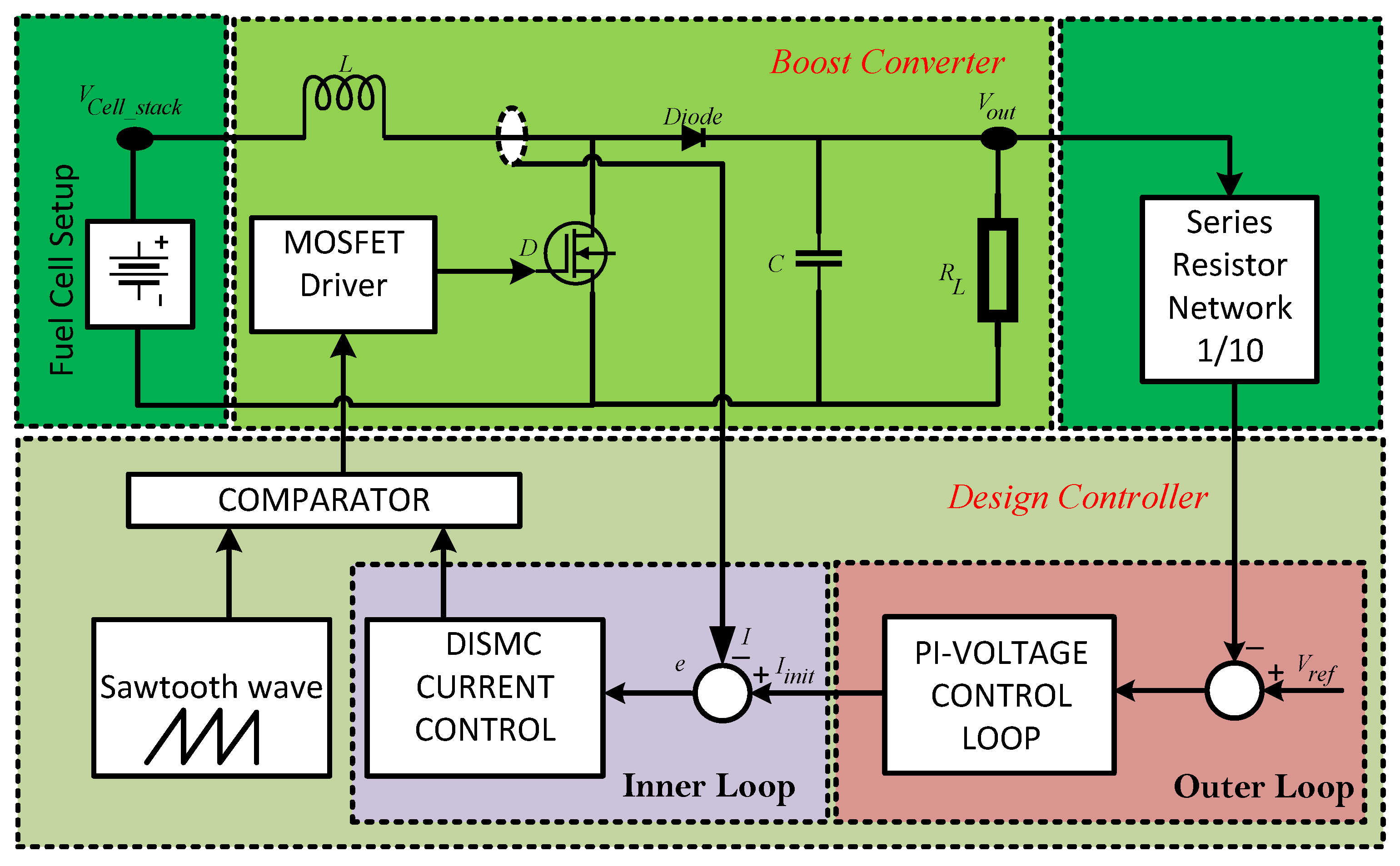
2. System Description

A PEMFC-based power system consists of a fuel cell and a DC-DC boost converter with a high output capacitance. A fuel cell is composed of bipolar plates with a gas diffusion mechanism and chemical exchange membranes. The hydrogen reacts with the oxygen in the presence of a catalyst, resulting in DC power with water and heat as byproducts of the chemical reaction.
The open circuit voltage of a single bipolar plate of a fuel cell stack is around 1 V, which drops significantly when a load is connected. This drop is due to the internal resistance of the cell, resulting from the construction of the electrode and the membrane. Hence, a fuel cell represents a typical power source, having low voltage and high current characteristics. In order to utilize the fuel cell in power systems, it is necessary to boost the voltages before applying to the load, which is achieved using a PWM-type DC-DC boost converter. It operates on the principle of storing electrical energy in a switching inductor that transfers it to a capacitor, resulting in boosted output voltage. Therefore, a DC-DC power converter is an integral part of this power system.
Figure 1 shows the key components of the system consisting of a controller for fuel regulation and DC-DC boost converter. The associated control strategies are developed, and finally a new technique based on DISMC is proposed to provide a constant output voltage. It is ensured that the chemical reactants are fully humidified before entering the fuel cell, and the flow rate of hydrogen is directly proportional to the flow rate of air; therefore, by controlling the blower voltage, the flow rates of both hydrogen and air are controlled. The heat produced during the exothermic reaction is removed by a fan-based air-cooled mechanism. Thus, the model for a fuel cell can be reduced to a voltage source, having unregulated voltage, which is regulated by the control circuitry illustrated in Figure 2.

3. Mathematical Model

The mathematical modeling of the system is described in this section.

3.1. PEMFC Stack Voltage

PEMFC model is built upon founding electrochemical equations, which are detailed in [4,65,66,67]. Figure 1 represents the system level block diagram that shows a fuel cell setup, where a PID controller ensures an optimum blow rate, W b l , by controlling the blower voltage, V b l , for maximum efficiency. The unregulated voltage of the fuel cell stack, V c e l l _ s t a c k , is fed to the power converter system, which is responsible for its regulation. V c e l l _ s t a c k is defined as the difference between the FC thermodynamic potential, V t h e r m o , and voltage losses outlined by its polarization curve, V p o l a r i z a t i o n for the total number of cells in a stack, η t o t a l . The polarization curve elucidates the variations in voltage behavior of the stack against the applied current density.
V c e l l _ s t a c k = V t h e r m o V p o l a r i z a t i o n × η t o t a l
Thermodynamic potential is the theoretical open circuit voltage drop which is principally based on Nernst expression with T c e l l _ s t a c k representing the stack operating temperature. The Nernst potential specified at standard temperature readings is defined by the equation below:
V t h e r m o = 1.229 8.5 × 10 4 · T c e l l _ s t a c k 298.15 + R T c e l l _ s t a c k 2 F · ln H 2 p r e s s u r e · O 2 p r e s s u r e 1 2
where H 2 p r e s s u r e and O 2 p r e s s u r e 1 2 represent the partial pressures for hydrogen and oxygen, respectively, R stands for the universal gas constant, while F denotes Faraday’s constant.
The potential drop by V p o l a r i z a t i o n is defined by
V p o l a r i z a t i o n = V a c t i v a t i o n + V r e s i s t i v e + V m a s s _ c o n c e r n t r a t i o n
Among the three potential drops, V a c t i v a t i o n accounts for the major voltage loss and is given by the equation below:
V a c t i v a t i o n = κ 1 κ 2 T c e l l _ s t a c k + κ 3 T c e l l _ s t a c k ln O 2 c o n c e n t r a t i o n + κ 4 T c e l l _ s t a c k ln ρ i
where ρ i is the current density, and κ j is the constants with j ranging from 1 to 4. The values of κ 1 , κ 2 , κ 3 and κ 4 are 0.9514 , 0.00312 , 0.000187 and 0.000074 , respectively. The O 2 c o n c e n t r a t i o n represents the oxygen gas concentration and is defined by the equation below:
O 2 c o n c e n t r a t i o n = O 2 p r e s s u r e 1 2 5.08 × 10 6 · e 498 T c e l l _ s t a c k
Impedance in the ion and electron flow accounts for resistive or ohmic polarization and is stated by the equations below:
V r e s i s t i v e = ρ i × Ω r e s i s t i v e
Ω r e s i s t i v e = Ω i o n i c + Ω e l e c t + Ω c o n t a c t
where Ω i o n i c is the ionic resistance of the electrolyte, Ω e l e c t defines the electrical resistance of cell plates, and Ω c o n t a c t is the contact resistance of the electrodes. For PEMFC, Ω i o n i c accounts for almost all of the resistive polarization due to specific membrane characteristics.
Polarization exposition for reactant consumption by electrodes generating concentration gradient is given by the V m a s s _ c o n c e n t r a t i o n equation below:
V m a s s _ c o n c e n t r a t i o n = R T c e l l _ s t a c k n F ln 1 1 ρ i ρ i l
where n = 4 represents two electrons for each hydrogen molecule and ρ i l is the limiting current density.
It is important to mention that including the dynamics of the fuel cell in Equation (1) can have an impact on the efficiency of the fuel cell. In case of the proposed technique where a PID controller is used in the first stage, there will be no significant improvement, as the controllers are experimentally tuned for the best performance. However, there will be a significant impact on the efficiency in cases where advanced nonlinear controllers are used at the fuel cell efficiency stage.

3.2. Power Converter

Dynamics of a boost converter designed on first principles of knowledge are defined by Equations (9) and (10), where V c e l l _ s t a c k is the output voltage of PEMFC and V o u t is the stable and uniform voltage of the boost converter.
I ˙ = 1 u 1 L · V o u t + 1 L · V c e l l _ s t a c k
V ˙ o u t = 1 u 1 C · I 1 R C · V o u t .
where u = 0 , 1 represents the switching signal, also termed as control input, L is the coil inductance, C is the storage capacitance, and R L is the load resistance defined by Equation (11).
R L = R i n + Δ R
R i n represents the initial resistance value, whereas Δ R is the uncertain change in the resistance.
Owing to Equations (9) and (10), the system exhibits non-minimum phase behavior, forcing it to be implemented in a two-loop fashion, wherein the inner loop controls the current based on DISMC, while the outer loop controls the voltage with the PI-based approach.

3.3. Hybrid Model

The composite and dynamic approach for the two-loop implementation of a hybrid boost converter is approached. The control signal u ^ ˙ consists of two parts: the first part is an analog signal, u 0 ^ ˙ , designed using the pole-placement technique, while u 1 ^ ˙ is the discontinuous part used to cancel out unknown disturbances, and is presented below.
u ^ ˙ = u 0 ^ ˙ + u 1 ^ ˙
The current error, e, is defined as e = I i n i t I , where I i n i t is the reference current. The continuous part of control Equation (12) is described as
u 0 ^ ˙ = η e + k e d t
where η and k are positive constants representing the gain of the controller. By taking the time derivative of error, e, and by substituting the value of I ˙ from Equation (9), e ˙ becomes Equation (14):
e ˙ = I i n i t ˙ + u ^ 1 L V o u t 1 L V c e l l _ s t a c k
and u ^ = 1 u . With this elaboration, the robust integral sliding surface is generated by the equation framework given in Equations (15) to (20):
s = x e + z
where x e represents the systems equations and is defined by Equation (16):
x e = e ˙ + λ e
Taking the derivative of Equation (16),
x ˙ e = e ¨ + λ e ˙
z is the integral component in Equation (15) and its derivative is defined by Equation (18).
z ˙ = λ e ˙ u 0 ^ ˙
with the initial condition specified by z 0 = x e . Taking the derivative of Equation (15) with respect to time gives Equation (19).
s ˙ = x ˙ e + z ˙ t
and substituting Equations (17) and (18) into Equation (19) produces Equation (20).
s ˙ = e ¨ u 0 ^ ˙
To design the discontinuous part, we take the derivative of Equation (14), and incorporate the system dynamics:
e ¨ = I ¨ i n i t + u ^ ˙ · 1 L V o u t 1 L V c e l l _ s t a c k + u ^ 2 L C I + u ^ R i n L C V o u t
and by substituting Equation (21) into (20), we obtain Equation (22)
s ˙ = I ¨ i n i t + u ^ ˙ · 1 L V o u t 1 L V c e l l _ s t a c k + u ^ 2 L C I + u ^ R i n L C V o u t u 0 ^ ˙
By the existence of the sliding mode condition D × s i g n s = s ˙ and using the equation of u ^ ˙ , Equation (22) can be rewritten as
D × s i g n s = I ¨ i n i t + u 0 ^ ˙ + u 1 ^ ˙ · 1 L V o u t 1 L V c e l l _ s t a c k + u ^ 2 L C I + u ^ R i n L C V o u t u 0 ^ ˙
where duty cycle, D + . The discontinuous control u 1 ^ ˙ can now be extracted by Equation (23) as
u 1 ^ ˙ = L V o u t D × s i g n s + I ¨ i n i t u 0 ^ ˙ 1 + V o u t L 1 L V c e l l _ s t a c k + u ^ 2 L C I + u ^ R i n L C V o u t
The entire control law specifying the complete PWM modulated signal u ^ ˙ can now be rewritten using Equations (13) and (24) to give Equation (25)
u ^ ˙ = η e + k e d t L V o u t D × s i g n s + I ¨ i n i t u 0 ^ ˙ 1 + V o u t L 1 L V c e l l _ s t a c k + u ^ 2 L C I + u ^ R i n L C V o u t

3.4. Lyapunov Based Existence Condition

For the existing model, the Lyapunov stability can be defined as
V x , t = 1 2 s 2
By taking the derivative of Equation (26), we obtain Equation (27).
V ˙ x , t = s s ˙
Substituting Equation (22) and existence condition
V ˙ x , t = s I ¨ i n i t + u ^ ˙ · 1 L V o u t 1 L V c e l l _ s t a c k + u ^ 2 L C I + u ^ R i n Δ R L C V o u t u 0 ^ ˙
Equation (28) can be further elaborated as
V ˙ ( x , t ) = s D × s i g n s Δ R V o u t u ^ R i n R i n Δ R L C
where Δ R μ , the ultimate value of the load resistance uncertainty. Hence, Equation (29) can be redefined as
V ˙ x , t | s | D μ V o u t u ^ R i n ( R i n μ ) L C
Thus, when D > μ V o u t u ^ R i n ( R i n μ ) L C + θ , the time-domain derivative of the Lyapunov function becomes negative definite, where θ + and μ = 72 , proving s = 0 in a finite time.

4. Hardware Setup

A 100 W, 24 cell portable fuel cell device from Horizon Fuel Cell Technologies bearing the model number MT08M965-100 was employed. Its detailed specifications are provided in Table 2.
Table 3 shows the boost converter’s parameters, and Figure 3 shows the experimental setup. The electronic switch comprises IRF540 power MOSFET, having a channel resistance of 0.06 Ω and can sustain up to 20 A of continuous drain current. The converter operates at a switching frequency of 32 kHz, which is selected based on a trade-off between the switching losses and chattering amplitude. The output of the converter is fed to the control circuitry, through a series resistor network having an attenuation of 10, as shown in Figure 2.
Experiments show that the equivalent resistance of the MOSFET drain should be low enough to quickly discharge the capacitance of the body diode; a higher value adversely affects the device’s turn-off process. A 47 k Ω resistor is placed between the MOSFET gate and source to ensure the discharge of the gate capacitance. Another resistor with a value of 0.47 Ω is positioned in series with the inductor current to measure its instantaneous value. According to Ohm’s law, the current flowing through an inductor is I L = V m e R m e = 2.1 V m e . Hence, the voltage measured at R m e is multiplied by a factor of 2.1 to obtain the exact value of the inductor current. All hardware-related wave forms in this work were captured with a 70 MHz Rigol oscilloscope at the rate of 1 G s a m p l e s . Furthermore, the power supply that runs the control circuitry is accurate to 0.1 V.

5. Results and Discussion

A complete schematic of the system is shown in Figure 4. The controller is implemented using Artix-7 family FPGA with model XC7A35T-ICPG236C. The voltages from the PEMFC are fed to the FPGA. The 12-bit, 1 MSPS, on-board Xilinx analog-to-digital converter (XADC) interface operates at input values between 0 and 1 V, thus requiring a series network of resistive elements to convert the input levels to the desired values. The inductor current is also provided to this XADC. A moving average filter is applied to the samples after every 10 μs. The extracted PWM signal with the required duty cycle is fed to the DC-DC boost converter implemented with the help of discrete components. Since FPGA implements the controller in the digital domain, all the fractional values are handled using signed fixed-point number representation.
The system is also simulated to validate the mathematical model and results. The simulations were performed using Runge–Kutta (ODE4) solver, having a fixed step size of 10−8 in the Simulink environment. The results suggest that the simulation outputs resemble quite accurately the experimental results. It is observed that the unmodeled dynamics of the system as well as the uncertainties of the experimental setup do have an impact, causing a slight variation between the experimental results and simulations.

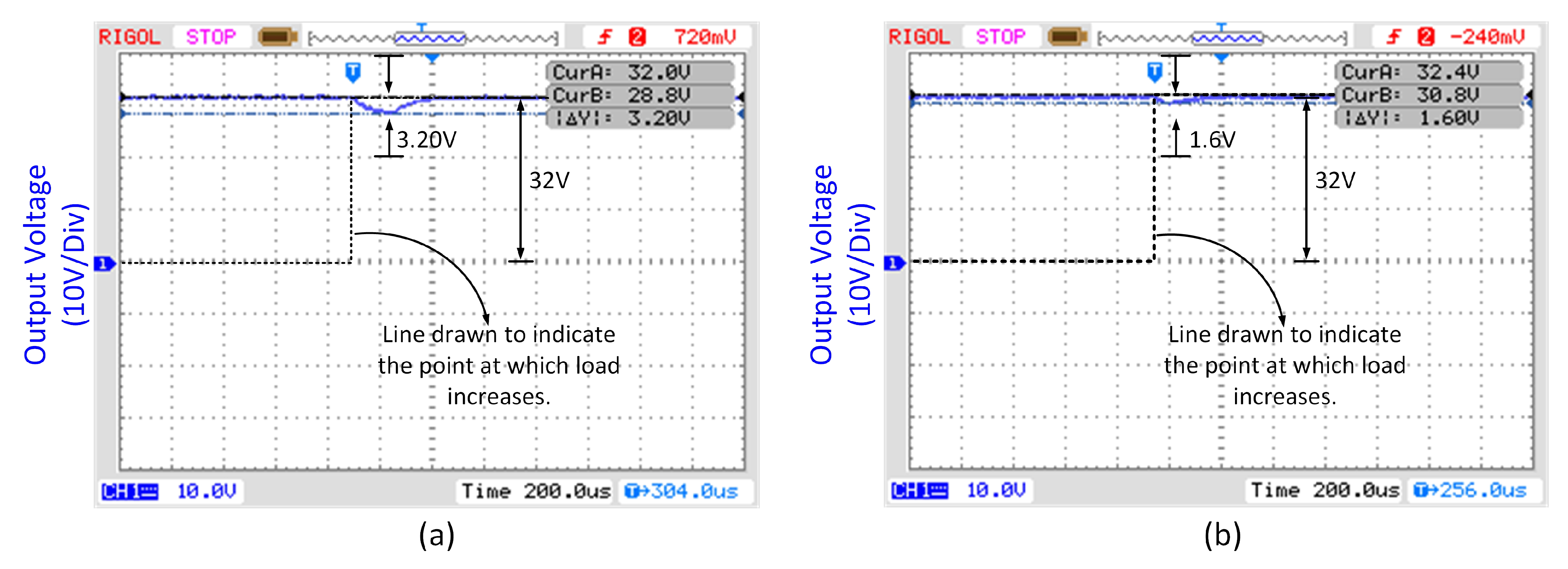
5.1. Steady-State Error and Transient Response

For the sake of experimental comparison between the proposed technique and conventional controllers, a PI controller is implemented, and the results are shown in Figure 5. Experiments show that the conventional system has a rise time, t r , of 45.2 ms and settles, t s , in 83.82 ms. Computer simulations of the same are also performed to validate the mathematical model. Simulations show that the PI-based system has a rise and settling time of 44.1 ms and 82.5 ms respectively. The experimental results of the proposed DISMC-based PEMFC system are shown in Figure 6. The system shows superior performance with a rise time, t r , of 29.2 ms and a settling time, t s , of 54.32 ms, whereas the simulations show 28.3 ms and 52.69 ms of the rise and settling time, respectively. There is a very close match between the simulations and the experimental findings; however, there is a small difference between the simulation and practical results due to the unmodeled dynamics and measuring inaccuracies. Both of the controllers are regulated at 32 V output and exhibit no steady-state error. The system shows an improvement of 35.4% in rise time and 34.0% in settling time, which is a direct result of the fact that the discontinuous function is implemented directly, and no indirect method is used to calculate the equivalent control.
The figure exhibiting the control effort obtained through simulation is shown in Figure 7.

5.2. Robustness to Load Variations

In order to validate the robustness of the system, an experimental setup using a Rigol function generator with a switching frequency of 10 kHz is used. The function generator’s output is connected to the base of a NPN transistor C1383. This drives a PNP power transistor TIP147, which connects and disconnects an additional load of 47 Ω from the nominal load of 82 Ω . Thus, experiments are conducted with the load resistance abruptly increased to assess the robustness of the proposed DISMC. Figure 8 shows that the conventional PI system exhibits an undershoot of 3.20 V, while DISMC demonstrates an improvement of 50% by decreasing the voltage dip to 1.6 V. PI recovers in 257 μ s, while DISMC recovers in 85 μ s. This shows a 67% improvement in recovery time.

6. Conclusions

With the rising CO2 pollution, researchers are focusing for the development of different clean energy solutions, and the fuel cell is among those electrochemical sources which are eco-friendly with zero emissions. Different types of SMC techniques have been reported in the literature to operate fuel cells under optimal conditions. However, there is a significant gap in the integration of power electronic techniques with the fuel cell to experimentally evaluate the performance. This research reports a significant improvement in the performance of the overall system using DISMC. In addition to this, a mathematical proof of the system’s stability is provided. The results display 35.4%, 34% and 50% improvements in the rise time, settling time and robustness, respectively. Moreover, simulations are performed that confirm a close resemblance with the experimental results. Future work could be extended in the direction to incorporate system time delays and temperature variations.

Author Contributions

A.Y. and A.R.Y. conceptualized the research and acted as the project administrators. M.B.S., S.Z., M.R., R.N., R.A.E.A. and S.B. acted as the investigators. All authors have read and agreed to the published version of the manuscript.

Funding

This work was supported through the Annual Funding track by the Deanship of Scientific Research (DSR), Vice Presidency for Graduate Studies and Scientific Research, King Faisal University, Saudi Arabia, Project Number AN000498 transformed to Project Number GRANT1504.

Data Availability Statement

Not applicable.

Acknowledgments

The authors would like to thank Aamer Iqbal Bhatti for his excellent guidance. We would also like to thank Karen Stanforth for her valuable inputs.

Conflicts of Interest

The authors declare no conflict of interest.

References

  1. Sharma, A.; Khan, R.A.; Sharma, A.; Kashyap, D.; Rajput, S. A Novel Opposition-Based Arithmetic Optimization Algorithm for Parameter Extraction of PEM Fuel Cell. Electronics 2021, 10, 2834. [Google Scholar] [CrossRef]
  2. Chen, W.M.; Kim, H. Energy, economic, and social impacts of a clean energy economic policy: Fuel cells deployment in Delaware. Energy Policy 2020, 144, 111617. [Google Scholar] [CrossRef]
  3. Xing, L.; Bai, X.; Gao, Y.; Cao, Z. Improving clean electrical power generation: A theoretical modelling analysis of a molten sodium hydroxide direct carbon fuel cell with low pollution. J. Clean. Prod. 2021, 281, 124623. [Google Scholar] [CrossRef]
  4. Godula-Jopek, D.I.h.A.; Westenberger, A.F. Fuel Cell Types: PEMFC/DMFC/AFC/PAFC//MCFC/SOFC/. In Encyclopedia of Energy Storage; Cabeza, L.F., Ed.; Elsevier: Oxford, UK, 2022; pp. 250–265. [Google Scholar] [CrossRef]
  5. Hosseini, S.E. 4.12-Hydrogen and Fuel Cells in Transport Road, Rail, Air, and Sea. In Comprehensive Renewable Energy, 2nd ed.; Letcher, T.M., Ed.; Elsevier: Oxford, UK, 2022; pp. 317–342. [Google Scholar] [CrossRef]
  6. Yang, B.; Li, J.; Li, Y.; Guo, Z.; Zeng, K.; Shu, H.; Cao, P.; Ren, Y. A critical survey of proton exchange membrane fuel cell system control: Summaries, advances, and perspectives. Int. J. Hydrogren Energy 2022, 47, 9986–10020. [Google Scholar] [CrossRef]
  7. Lin-Kwong-Chon, C.; Grondin-Pérez, B.; Kadjo, J.J.A.; Damour, C.; Benne, M. A review of adaptive neural control applied to proton exchange membrane fuel cell systems. Annu. Rev. Control 2019, 47, 133–154. [Google Scholar] [CrossRef]
  8. Yuan, H.; Dai, H.; Wei, X.; Ming, P. Model-based observers for internal states estimation and control of proton exchange membrane fuel cell system: A review. J. Power Sources 2020, 468, 228376. [Google Scholar] [CrossRef]
  9. Yuan, X.Z.; Nayoze-Coynel, C.; Shaigan, N.; Fisher, D.; Zhao, N.; Zamel, N.; Gazdzicki, P.; Ulsh, M.; Friedrich, K.A.; Girard, F.; et al. A review of functions, attributes, properties and measurements for the quality control of proton exchange membrane fuel cell components. J. Power Sources 2021, 491, 229540. [Google Scholar] [CrossRef]
  10. Hou, J.; Yang, M.; Ke, C.; Zhang, J. Control logics and strategies for air supply in PEM fuel cell engines. Appl. Energy 2020, 269, 115059. [Google Scholar] [CrossRef]
  11. Oliveira, T.R.; Krstić, M.; Tsubakino, D. Extremum Seeking for Static Maps With Delays. IEEE Trans. Autom. Control 2017, 62, 1911–1926. [Google Scholar] [CrossRef]
  12. He, H.; Quan, S.; Sun, F.; Wang, Y.X. Model Predictive Control With Lifetime Constraints Based Energy Management Strategy for Proton Exchange Membrane Fuel Cell Hybrid Power Systems. IEEE Trans. Ind. Electron. 2020, 67, 9012–9023. [Google Scholar] [CrossRef]
  13. Chatrattanawet, N.; Hakhen, T.; Kheawhom, S.; Arpornwichanop, A. Control structure design and robust model predictive control for controlling a proton exchange membrane fuel cell. J. Clean. Prod. 2017, 148, 934–947. [Google Scholar] [CrossRef]
  14. Chen, Q.; Gao, L.; Dougal, R.A.; Quan, S. Multiple model predictive control for a hybrid proton exchange membrane fuel cell system. J. Power Sources 2009, 191, 473–482. [Google Scholar] [CrossRef]
  15. Li, G.; Fu, H.; Madonski, R.; Czeczot, J.; Nowak, P.; Lakomy, K.; Sun, L. Feed-forward offset-free model predictive temperature control for proton exchange membrane fuel cell: An experimental study. ISA Trans. 2021; in press. [Google Scholar] [CrossRef]
  16. Ekaputri, C.; Syaichu-Rohman, A. Model predictive control (MPC) design and implementation using algorithm-3 on board SPARTAN 6 FPGA SP605 evaluation kit. In Proceedings of the 2013 3rd International Conference on Instrumentation Control and Automation (ICA), Bali, Indonesia, 28–30 August 2013; pp. 115–120. [Google Scholar] [CrossRef]
  17. Liu, Z.; Chen, H.; Peng, L.; Ye, X.; Xu, S.; Zhang, T. Feedforward-decoupled closed-loop fuzzy proportion-integral-derivative control of air supply system of proton exchange membrane fuel cell. Energy 2022, 240, 122490. [Google Scholar] [CrossRef]
  18. Mahali, A.P.; Babu Gara, U.B.; Mullapudi, S. Fuzzy Logic based Control Strategies for Proton Exchange Membrane Fuel Cell System. IFAC-PapersOnLine 2022, 55, 703–708. [Google Scholar] [CrossRef]
  19. Chen, X.; Xu, J.; Fang, Y.; Li, W.; Ding, Y.; Wan, Z.; Wang, X.; Tu, Z. Temperature and humidity management of PEM fuel cell power system using multi-input and multi-output fuzzy method. Appl. Therm. Eng. 2022, 203, 117865. [Google Scholar] [CrossRef]
  20. AbouOmar, M.S.; Su, Y.; Zhang, H.; Shi, B.; Wan, L. Observer-based interval type-2 fuzzy PID controller for PEMFC air feeding system using novel hybrid neural network algorithm-differential evolution optimizer. Alex. Eng. J. 2022, 61, 7353–7375. [Google Scholar] [CrossRef]
  21. Behrooz, F.; Mariun, N.; Marhaban, M.; Mohd Radzi, M.A.; Ramli, A. Review of Control Techniques for HVAC Systems—Nonlinearity Approaches Based on Fuzzy Cognitive Maps. Energies 2018, 11, 495. [Google Scholar] [CrossRef]
  22. Souissi, A. Adaptive sliding mode control of a PEM fuel cell system based on the super twisting algorithm. Energy Rep. 2021, 7, 3390–3399. [Google Scholar] [CrossRef]
  23. Derbeli, M.; Barambones, O.; Farhat, M.; Ramos-Hernanz, J.A.; Sbita, L. Robust high order sliding mode control for performance improvement of PEM fuel cell power systems. Int. J. Hydrogen Energy 2020, 45, 29222–29234. [Google Scholar] [CrossRef]
  24. Javaid, U.; Mehmood, A.; Arshad, A.; Imtiaz, F.; Iqbal, J. Operational Efficiency Improvement of PEM Fuel Cell—A Sliding Mode Based Modern Control Approach. IEEE Access 2020, 8, 95823–95831. [Google Scholar] [CrossRef]
  25. Javaid, U.; Iqbal, J.; Mehmood, A.; Uppal, A.A. Performance improvement in polymer electrolytic membrane fuel cell based on nonlinear control strategies—A comprehensive study. PLoS ONE 2022, 17, e0264205. [Google Scholar] [CrossRef] [PubMed]
  26. Choe, S.Y.; Lee, J.G.; Ahn, J.W.; Baek, S.H. Integrated modeling and control of a PEM fuel cell power system with a PWM DC/DC converter. J. Power Sources 2007, 164, 614–623. [Google Scholar] [CrossRef]
  27. Chen, K.; Hou, Y.; Jiang, C.; Pan, X.; Hao, D. Experimental investigation on statistical characteristics of cell voltage distribution for a PEMFC stack under dynamic driving cycle. Int. J. Hydrogen Energy 2021, 46, 38469–38481. [Google Scholar] [CrossRef]
  28. Chen, X.; Fang, Y.; Liu, Q.; He, L.; Zhao, Y.; Huang, T.; Wan, Z.; Wang, X. Temperature and voltage dynamic control of PEMFC Stack using MPC method. Energy Rep. 2022, 8, 798–808. [Google Scholar] [CrossRef]
  29. Cao, Y.; Li, Y.; Zhang, G.; Jermsittiparsert, K.; Nasseri, M. An efficient terminal voltage control for PEMFC based on an improved version of whale optimization algorithm. Energy Rep. 2020, 6, 530–542. [Google Scholar] [CrossRef]
  30. Roux Oliveira, T.; Revoredo, T. Monitoring Function based Extremum Seeking for Fuel Cell Energy Applications. In Proceedings of the International Congress of Mechanical Engineering (COBEM), Rio de Janeiro, Brazil, 6–11 December 2015. [Google Scholar]
  31. Awais, M.; Yasin, A.R.; Riaz, M.; Saqib, B.; Zia, S.; Yasin, A. Robust Sliding Mode Control of a Unipolar Power Inverter. Energies 2021, 14, 5405. [Google Scholar] [CrossRef]
  32. Sankar, K.; Saravanakumar, G.; Jana, A.K. Nonlinear multivariable control of an integrated PEM fuel cell system with a DC-DC boost converter. Chem. Eng. Res. Des. 2021, 167, 141–156. [Google Scholar] [CrossRef]
  33. Kuo, J.K.; Wang, C.F. An integrated simulation model for PEM fuel cell power systems with a buck DC–DC converter. Int. J. Hydrogen Energy 2011, 36, 11846–11855. [Google Scholar] [CrossRef]
  34. Sabanovic, A. Buck converter regulator operating in the sliding mode. In Proceedings of the PCI, Orlando, FL, USA, 19–21 April 1983. [Google Scholar]
  35. Venkataramanan, R. Sliding Mode Control of Power Converters; California Institute of Technology: Pasadena, CA, USA, 1986. [Google Scholar]
  36. Carpita, M.; Marchesoni, M. Experimental study of a power conditioning system using sliding mode control. IEEE Trans. Power Electron. 1996, 11, 731–742. [Google Scholar] [CrossRef]
  37. Hizarci, H.; Pekperlak, U.; Arifoglu, U. Conducted emission suppression using an EMI filter for grid-tied three-phase/level T-type solar inverter. IEEE Access 2021, 9, 67417–67431. [Google Scholar] [CrossRef]
  38. Qi, W.; Li, S.; Tan, S.C.; Hui, S.R. Parabolic-modulated sliding-mode voltage control of a buck converter. IEEE Trans. Ind. Electron. 2017, 65, 844–854. [Google Scholar] [CrossRef]
  39. Repecho, V.; Biel, D.; Ramos-Lara, R.; Vega, P.G. Fixed-switching frequency interleaved sliding mode eight-phase synchronous buck converter. IEEE Trans. Power Electron. 2017, 33, 676–688. [Google Scholar] [CrossRef]
  40. Al-Wesabi, I.; Fang, Z.; Wei, Z.; Dong, H. Direct sliding mode control for dynamic instabilities in DC-link voltage of standalone photovoltaic systems with a small capacitor. Electronics 2022, 11, 133. [Google Scholar] [CrossRef]
  41. Yao, S.; Gao, G.; Gao, Z. On multi-axis motion synchronization: The cascade control structure and integrated smc–adrc design. ISA Trans. 2021, 109, 259–268. [Google Scholar] [CrossRef]
  42. Yasin, A.R.; Ashraf, M.; Bhatti, A.I. A Novel Filter Extracted Equivalent Control Based Fixed Frequency Sliding Mode Approach for Power Electronic Converters. Energies 2019, 12, 853. [Google Scholar] [CrossRef]
  43. Gao, M.; Wang, D.; Li, Y.; Yuan, T. Fixed frequency pulse-width modulation based integrated sliding mode controller for phase-shifted full-bridge converters. IEEE Access 2017, 6, 2181–2192. [Google Scholar] [CrossRef]
  44. Repecho, V.; Biel, D.; Arias, A. Fixed switching period discrete-time sliding mode current control of a PMSM. IEEE Trans. Ind. Electron. 2017, 65, 2039–2048. [Google Scholar] [CrossRef]
  45. Chincholkar, S.H.; Jiang, W.; Chan, C.Y. An improved PWM-based sliding-mode controller for a DC–DC cascade boost converter. IEEE Trans. Circuits Syst. II Express Briefs 2017, 65, 1639–1643. [Google Scholar] [CrossRef]
  46. Li, J.; Liu, Z.; Su, Q. Improved adaptive backstepping sliding mode control for a three-phase PWM AC–DC converter. IET Control Theory Appl. 2019, 13, 854–860. [Google Scholar] [CrossRef]
  47. Repecho, V.; Biel, D.; Olm, J.M.; Colet, E.F. Switching frequency regulation in sliding mode control by a hysteresis band controller. IEEE Trans. Power Electron. 2016, 32, 1557–1569. [Google Scholar] [CrossRef]
  48. Ortiz-Castrillón, J.R.; Mejía-Ruiz, G.E.; Muñoz-Galeano, N.; López-Lezama, J.M.; Cano-Quintero, J.B. A sliding surface for controlling a semi-bridgeless boost converter with power factor correction and adaptive hysteresis band. Appl. Sci. 2021, 11, 1873. [Google Scholar] [CrossRef]
  49. Hoyos, F.E.; Candelo-Becerra, J.E.; Hoyos Velasco, C.I. Application of zero average dynamics and fixed point induction control techniques to control the speed of a DC motor with a buck converter. Appl. Sci. 2020, 10, 1807. [Google Scholar] [CrossRef]
  50. Muñoz, J.G.; Angulo, F.; Angulo-Garcia, D. Zero average surface controlled boost-flyback converter. Energies 2020, 14, 57. [Google Scholar] [CrossRef]
  51. Yasin, A.R.; Ashraf, M.; Bhatti, A.I.; Uppal, A.A. Fixed frequency sliding mode control of renewable energy resources in DC micro grid. Asian J. Control 2019, 21, 2074–2086. [Google Scholar] [CrossRef]
  52. Yasin, A.R.; Ashraf, M.; Bhatti, A.I. Fixed frequency sliding mode control of power converters for improved dynamic response in DC micro-grids. Energies 2018, 11, 2799. [Google Scholar] [CrossRef]
  53. Li, Z.; Wang, X.; Kong, M.; Chen, X. Bidirectional harmonic current control of brushless doubly fed motor drive system based on a fractional unidirectional converter under a weak grid. IEEE Access 2021, 9, 19926–19938. [Google Scholar] [CrossRef]
  54. Tan, S.C.; Lai, Y.M.; Tse, C.K.; Cheung, M.K. A fixed-frequency pulsewidth modulation based quasi-sliding-mode controller for buck converters. IEEE Trans. Power Electron. 2005, 20, 1379–1392. [Google Scholar] [CrossRef]
  55. Khan, I.; Bhatti, A.I.; Arshad, A.; Khan, Q. Robustness and Performance Parameterization of Smooth Second Order Sliding Mode Control. Int. J. Control Autom. Syst. 2016, 14, 681–690. [Google Scholar] [CrossRef]
  56. Abrishamifar, A.; Ahmad, A.; Mohamadian, M. Fixed switching frequency sliding mode control for single-phase unipolar inverters. IEEE Trans. Power Electron. 2011, 27, 2507–2514. [Google Scholar] [CrossRef]
  57. Ye, J.; Malysz, P.; Emadi, A. A fixed-switching-frequency integral sliding mode current controller for switched reluctance motor drives. IEEE J. Emerg. Sel. Top. Power Electron. 2014, 3, 381–394. [Google Scholar] [CrossRef]
  58. Huerta, S.C.; Alou, P.; Garcia, O.; Oliver, J.A.; Prieto, R.; Cobos, J. Hysteretic mixed-signal controller for high-frequency DC–DC converters operating at constant switching frequency. IEEE Trans. Power Electron. 2012, 27, 2690–2696. [Google Scholar] [CrossRef]
  59. Vidal-Idiarte, E.; Marcos-Pastor, A.; Garcia, G.; Cid-Pastor, A.; Martinez-Salamero, L. Discrete-time sliding-mode-based digital pulse width modulation control of a boost converter. IET Power Electron. 2015, 8, 708–714. [Google Scholar] [CrossRef]
  60. Yan, W.T.; Ho, C.N.M.; Chung, H.S.H.; Au, K.T. Fixed-frequency boundary control of buck converter with second-order switching surface. IEEE Trans. Power Electron. 2009, 24, 2193–2201. [Google Scholar] [CrossRef]
  61. Venkateswaran, R.; Yesudhas, A.A.; Lee, S.R.; Joo, Y.H. Integral sliding mode control for extracting stable output power and regulating DC-link voltage in PMVG-based wind turbine system. Int. J. Electr. Power Energy Syst. 2023, 144, 108482. [Google Scholar] [CrossRef]
  62. Armghan, H.; Yang, M.; Armghan, A.; Ali, N. Double integral action based sliding mode controller design for the back-to-back converters in grid-connected hybrid wind-PV system. Int. J. Electr. Power Energy Syst. 2021, 127, 106655. [Google Scholar] [CrossRef]
  63. Riaz, M.; Yasin, A.R.; Arshad Uppal, A.; Yasin, A. A novel dynamic integral sliding mode control for power electronic converters. Sci. Prog. 2021, 104, 00368504211044848. [Google Scholar] [CrossRef]
  64. Khan, Q.; Bhatti, A.I.; Iqbal, S.; Iqbal, M. Dynamic integral sliding mode for MIMO uncertain nonlinear systems. Int. J. Control Autom. Syst. 2011, 9, 151–160. [Google Scholar] [CrossRef]
  65. Omran, A.; Lucchesi, A.; Smith, D.; Alaswad, A.; Amiri, A.; Wilberforce, T.; Sodré, J.R.; Olabi, A.G. Mathematical model of a proton-exchange membrane (PEM) fuel cell. Int. J. Thermofluids 2021, 11, 100110. [Google Scholar] [CrossRef]
  66. Baschuk, J.J.; Li, X. A general formulation for a mathematical PEM fuel cell model. J. Power Sources 2005, 142, 134–153. [Google Scholar] [CrossRef]
  67. Xue, X.D.; Cheng, K.W.E.; Sutanto, D. Unified mathematical modelling of steady-state and dynamic voltage–current characteristics for PEM fuel cells. Electrochim. Acta 2006, 52, 1135–1144. [Google Scholar] [CrossRef]
Figure 1. Fuel cell setup with power control circuitry and its control system.
Electronics 11 02922 g001
Figure 2. Block diagram of power control circuitry.
Electronics 11 02922 g002
Figure 3. Hardware Setup.
Electronics 11 02922 g003
Figure 4. Schematic of the system.
Electronics 11 02922 g004
Figure 5. Results using conventional PI controller with fuel cell. (a) Hardware results. (b) Simulation results.
Electronics 11 02922 g005
Figure 6. Results showing performance of the proposed DISMC with PEMFC. (a) Hardware results. (b) Simulation results.
Electronics 11 02922 g006
Figure 7. Control effort obtained via simulation. (a) PID controller. (b) DISMC controller.
Electronics 11 02922 g007
Figure 8. Results showing robustness of the PI and proposed DISMC with PEMFC. (a) PI controller. (b) DISMC controller.
Electronics 11 02922 g008
Table 1. Converter control techniques summary.
Ref #Control TechniqueRelative CostConvergence SpeedParametric IndependenceComplexity
[63]Dynamic Integral SMC1ModerateFastIndependentLow
[38,39]Parabolic Modulated SMCLowFastDependentModerate
[42]Equivalent Control via Filter ExtractionLowReal-timeIndependentLow
[62]Double Integral SMCModerateFastIndependentHigh
[45,51,52,53,54,56,57]Fixed-Frequency via PWM2LowReal-timeDependentModerate
[43,61]Fixed-Frequency Integral SMCLowReal-timeDependentModerate
[60]Fixed-Frequency Boundary ControlLowReal-timeIndependentHigh
[58]Fixed-Frequency Mixed-signal Hysteresis ControlHighModerateIndependentHigh
[44,59]Discrete-Time SMCHighModerateIndependentHigh
[55]2nd Order SMCHighModerateIndependentModerate
[49,50]Zero Average DynamicsHighFastIndependentHigh
[46]Adaptive Backstepping SMCHighModerateIndependentHigh
[34,35,47,48]Hysteresis Band SMC *ModerateReal-timeIndependentLow
1 Sliding mode control (SMC). 2 Pulse-width modulation (PWM). * Provides variable switching frequency.
Table 2. Specifications of the Horizon Fuel Cell Technologies’ produced fuel cell used in this research.
ParameterDescription
TypePortable
Operating Temperature65 °C
Volume15 × 10.9 × 9.4 cm3
Weight90 g
Oxident SupplyOpen Cathode
Table 3. Boost Converter Specification.
SpecificationRepresentationValue
Input VoltageVcell_stack11–19 V
Output voltageVout32 V
CapacitanceC2200 µF
Coil inductanceL110 µH
Switching FrequencyF32 kHz
Load ResistorRinit82 Ω
Variation in LoadΔR0–47 Ω
Publisher’s Note: MDPI stays neutral with regard to jurisdictional claims in published maps and institutional affiliations.

