Figure 1.
Diameter schedule for rebars (dimensions are in mm).
Figure 1.
Diameter schedule for rebars (dimensions are in mm).
Figure 2.
A typical test setup for a repaired reinforced concrete (RC) member (dimensions are in mm).
Figure 2.
A typical test setup for a repaired reinforced concrete (RC) member (dimensions are in mm).
Figure 3.
Concrete compressive strength results.
Figure 3.
Concrete compressive strength results.
Figure 4.
Concrete tensile strength results.
Figure 4.
Concrete tensile strength results.
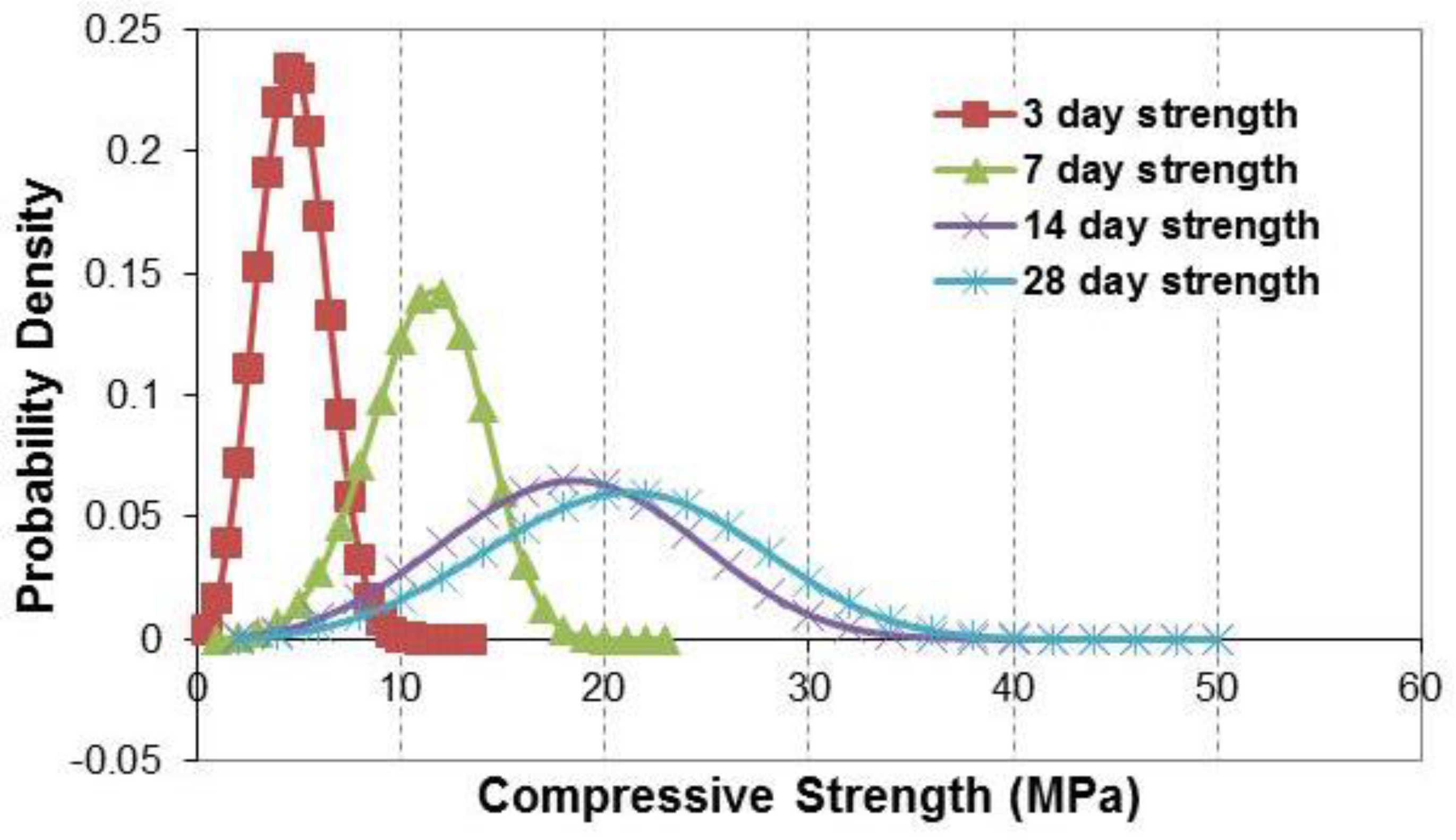
Figure 5.
Weibull distribution of concrete compressive strength.
Figure 5.
Weibull distribution of concrete compressive strength.
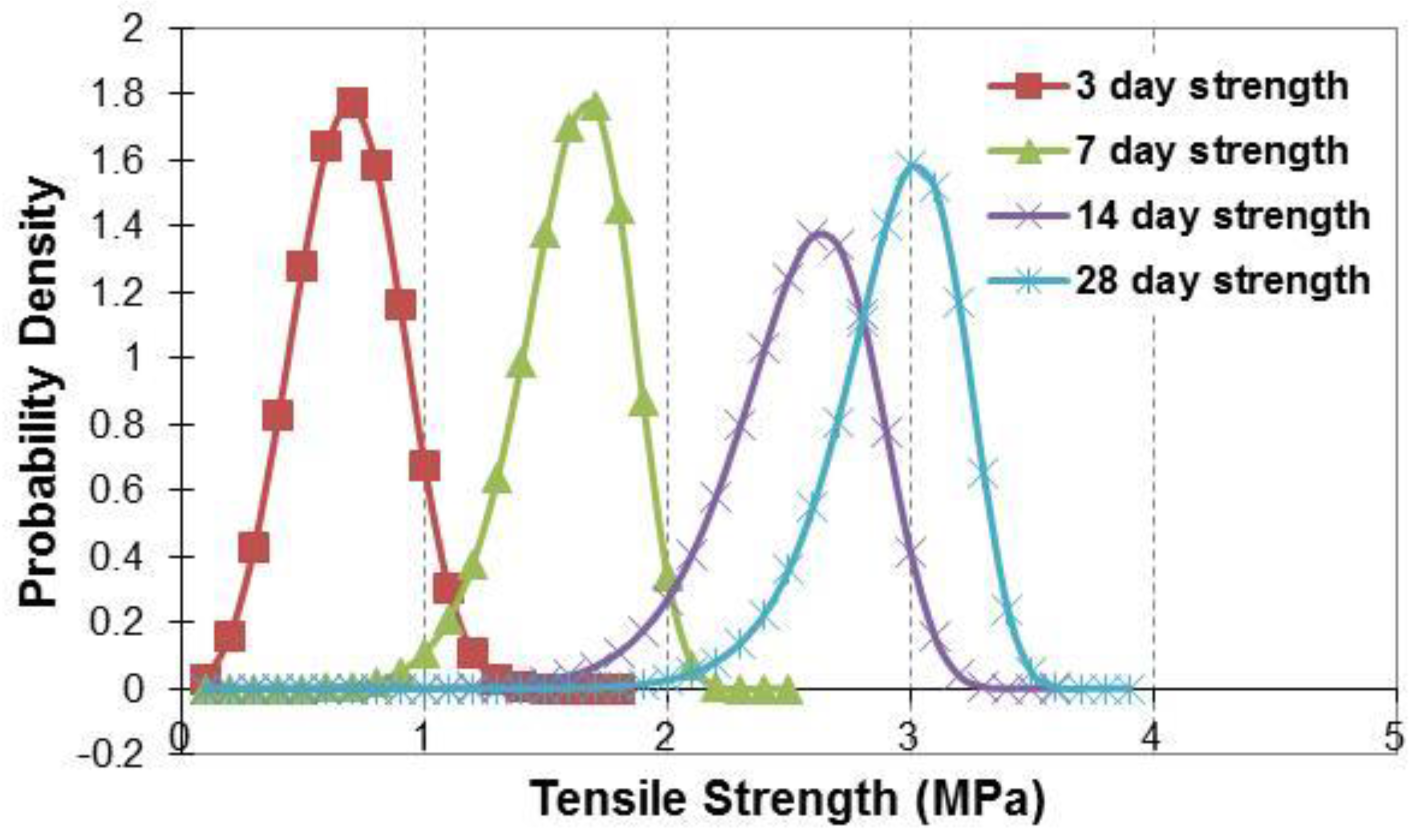
Figure 6.
Weibull distribution of concrete tensile strength.
Figure 6.
Weibull distribution of concrete tensile strength.
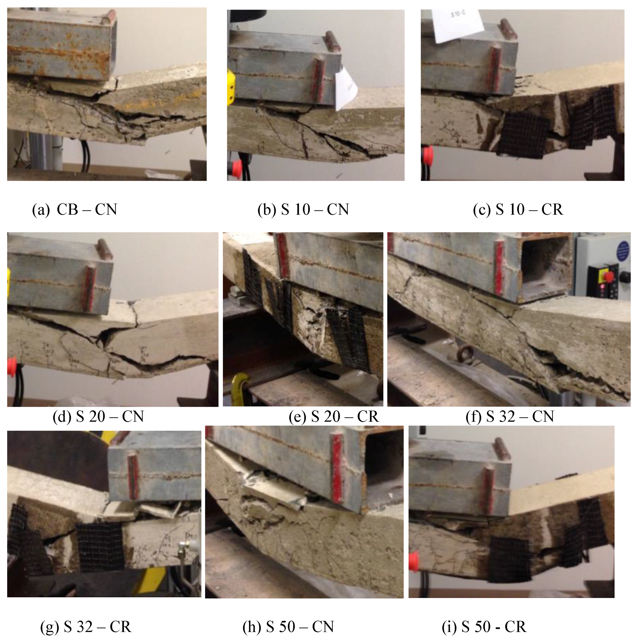
Figure 7.
Failure of control beam and beams with simulated corrosion.
Figure 7.
Failure of control beam and beams with simulated corrosion.
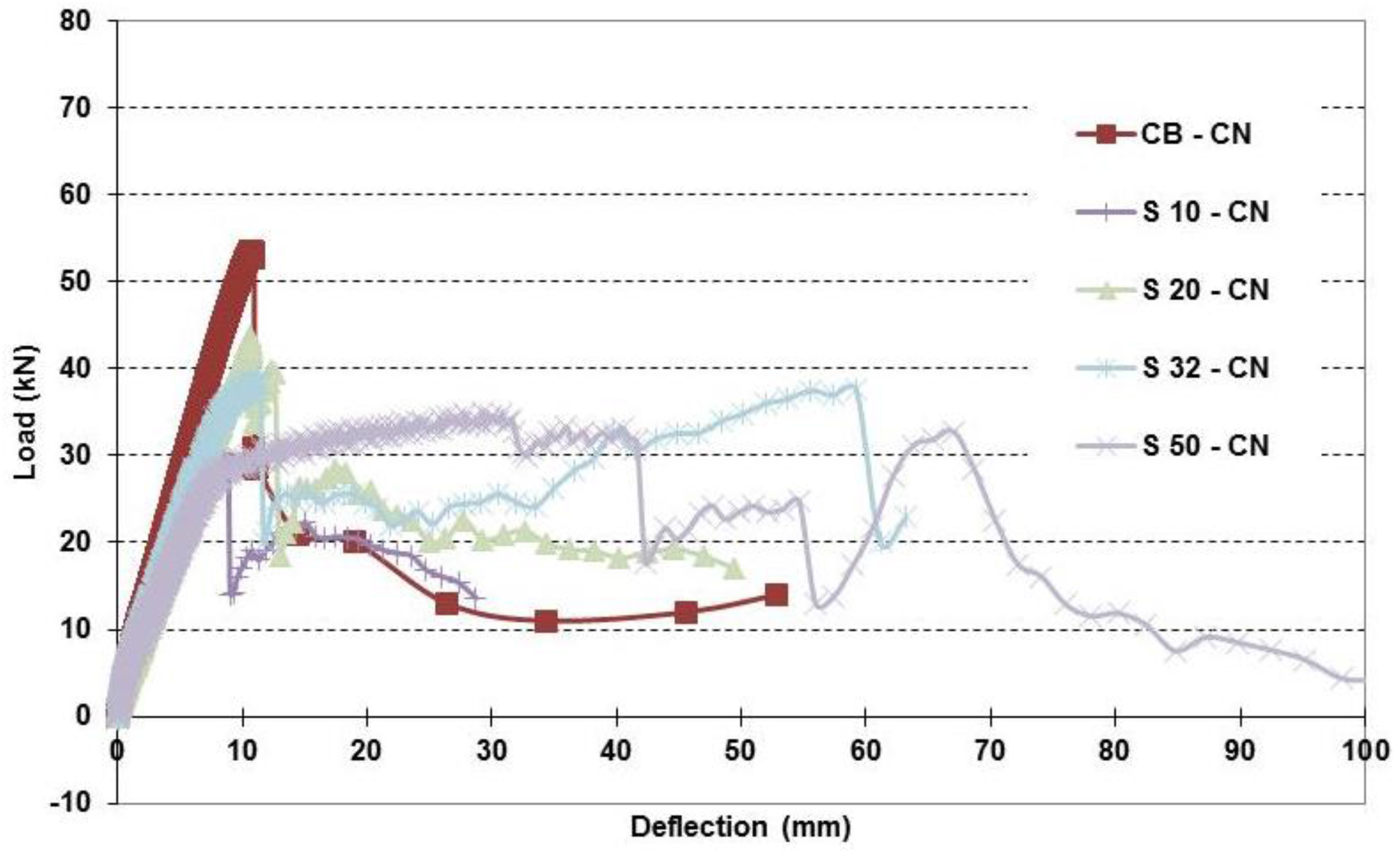
Figure 8.
Load-deflection relationships of control beam and beams with simulated corrosion.
Figure 8.
Load-deflection relationships of control beam and beams with simulated corrosion.
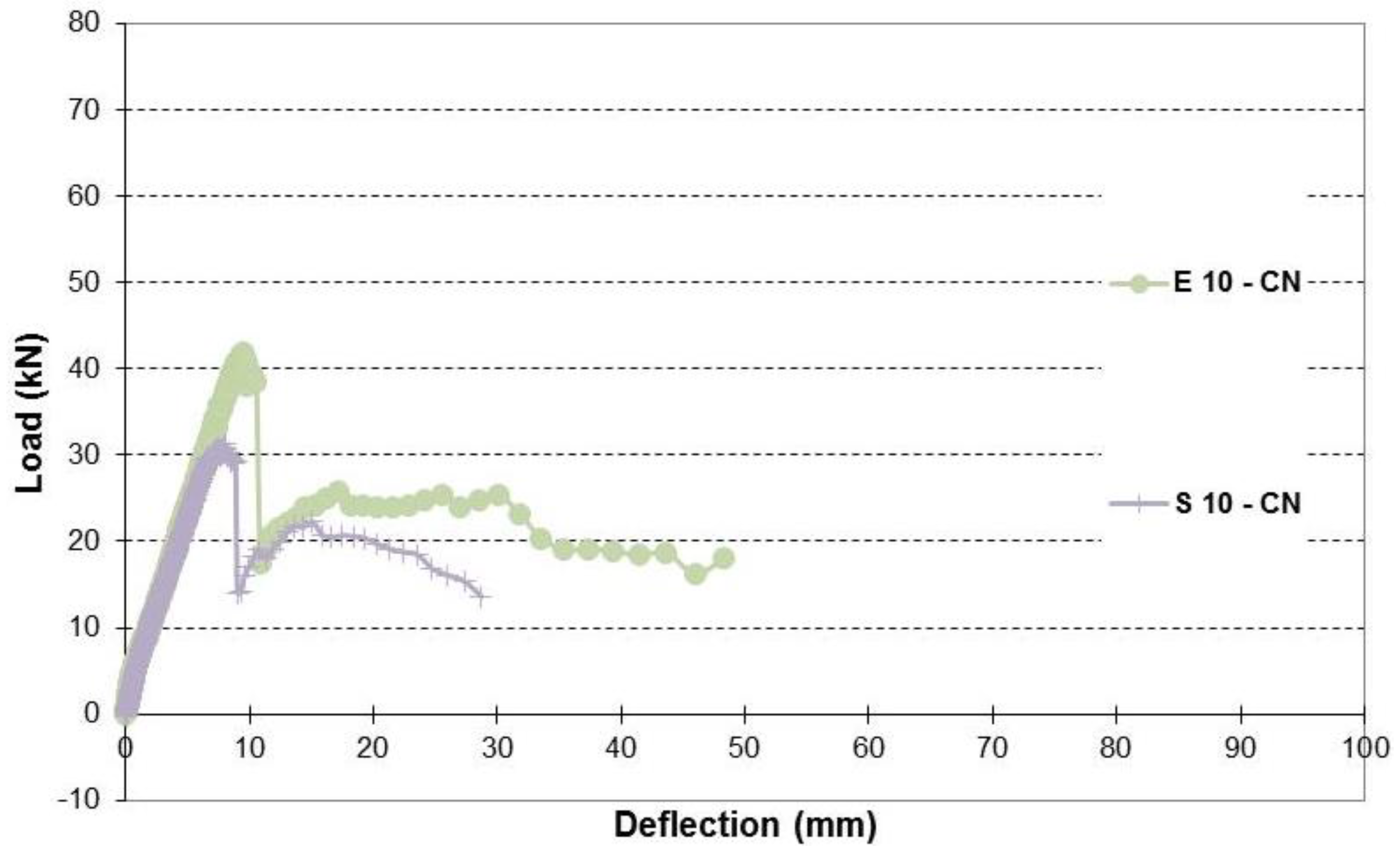
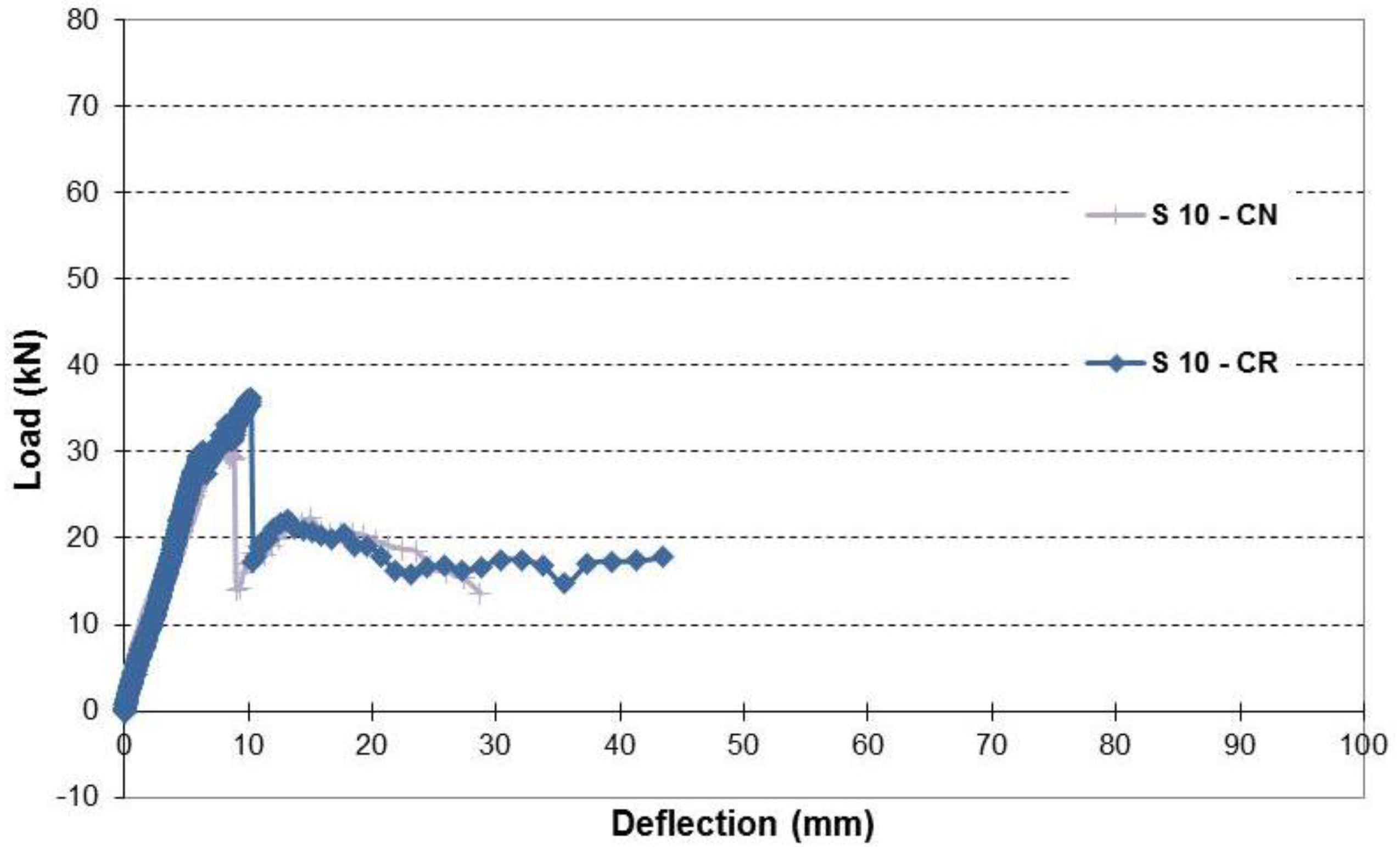
Figure 9.
Load-deflection relationship of beams with simulated 10% corrosion level.
Figure 9.
Load-deflection relationship of beams with simulated 10% corrosion level.
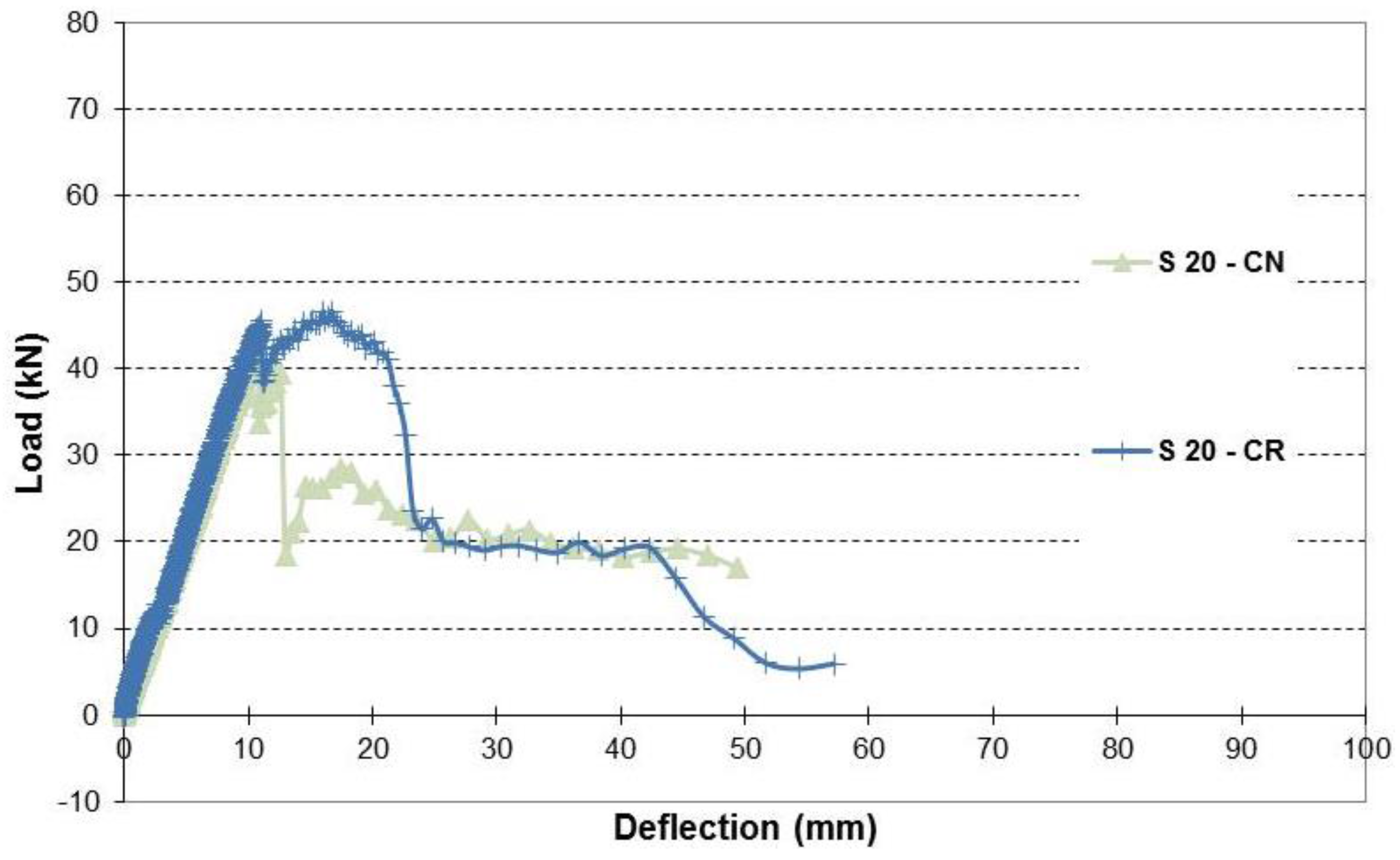
Figure 10.
Load-deflection relationship of beams with simulated 20% corrosion level.
Figure 10.
Load-deflection relationship of beams with simulated 20% corrosion level.
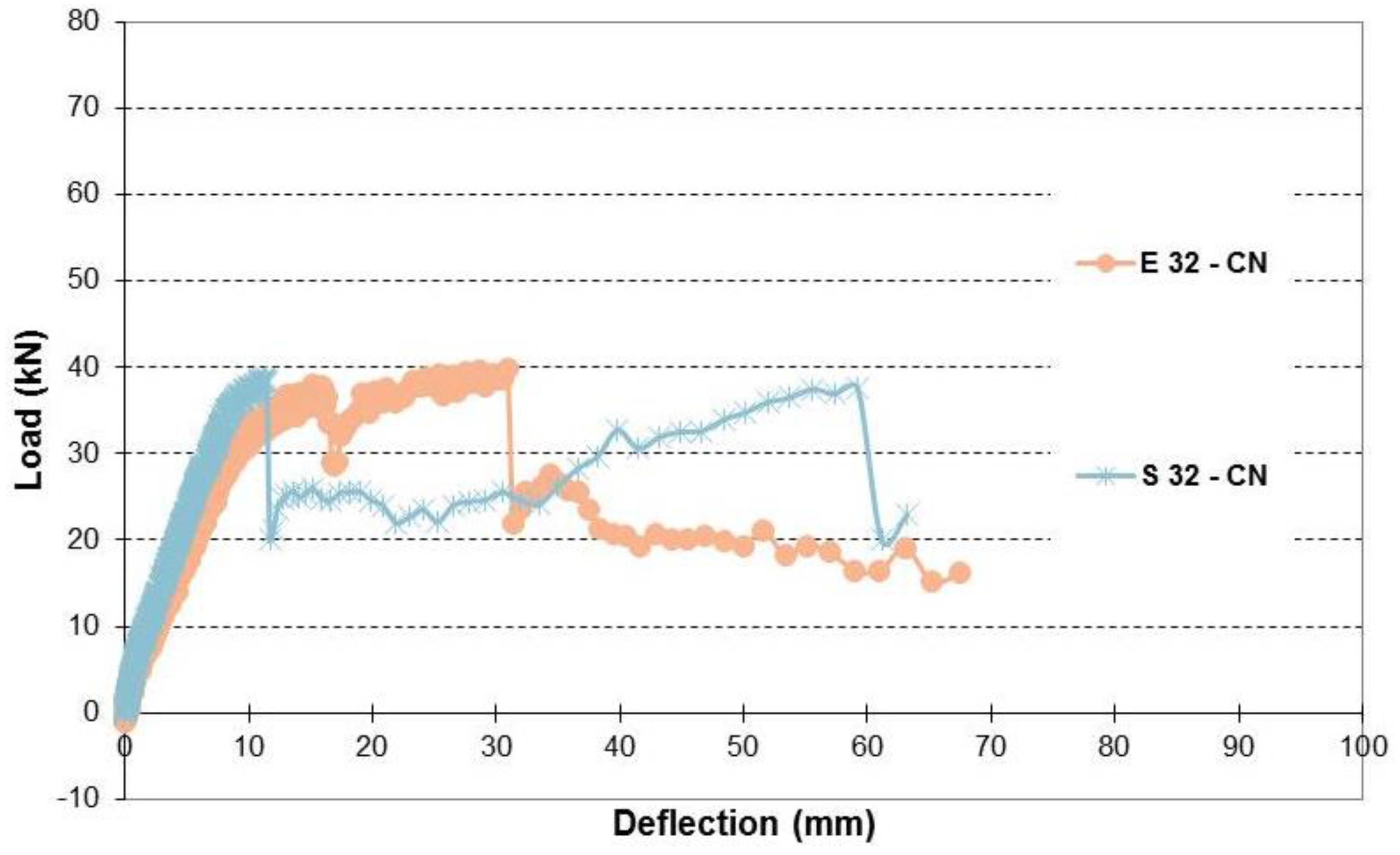
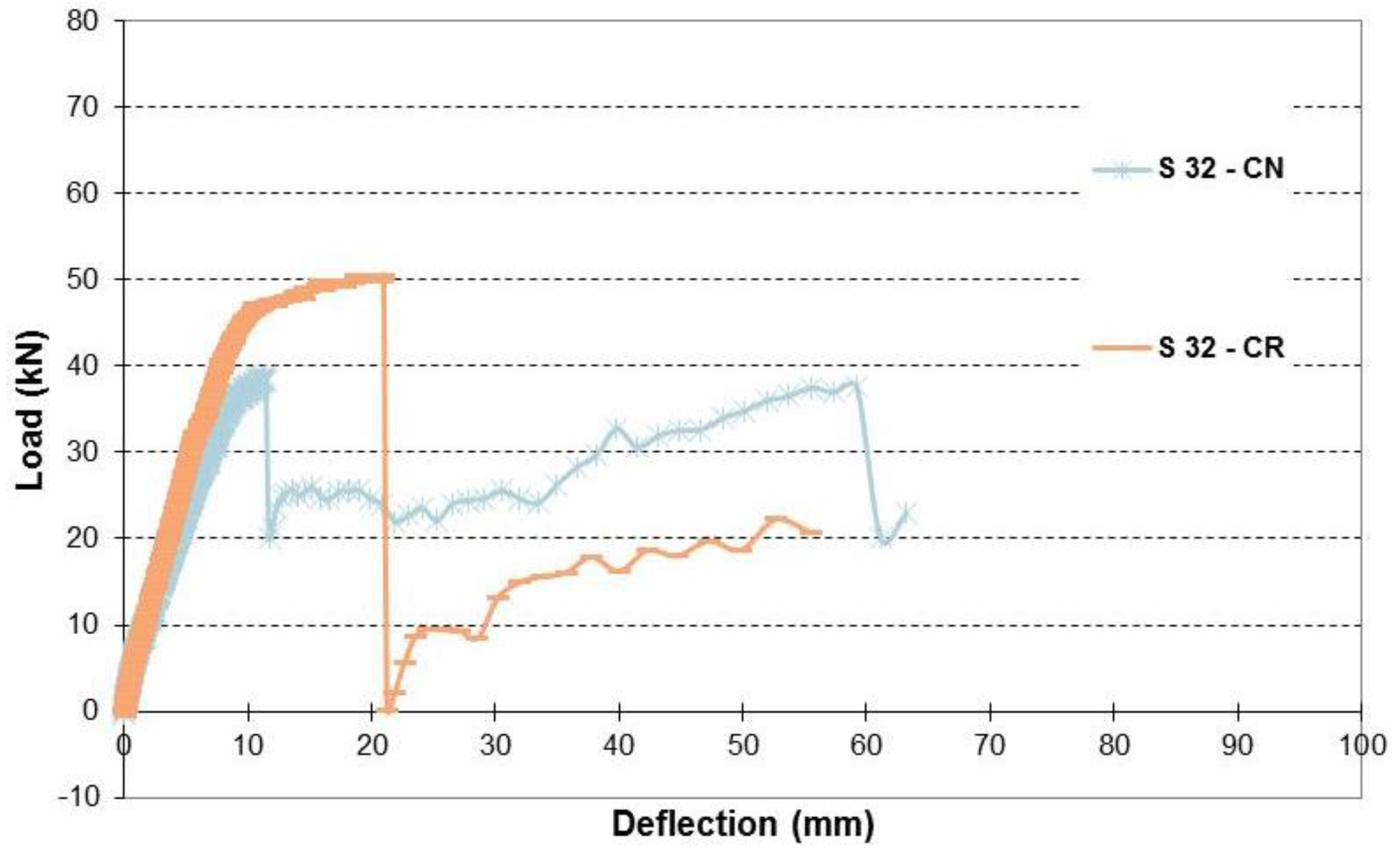
Figure 11.
Load-deflection relationship of beams with simulated 32% corrosion level.
Figure 11.
Load-deflection relationship of beams with simulated 32% corrosion level.
Figure 12.
Load-deflection relationship of beams with simulated 50% corrosion level.
Figure 12.
Load-deflection relationship of beams with simulated 50% corrosion level.
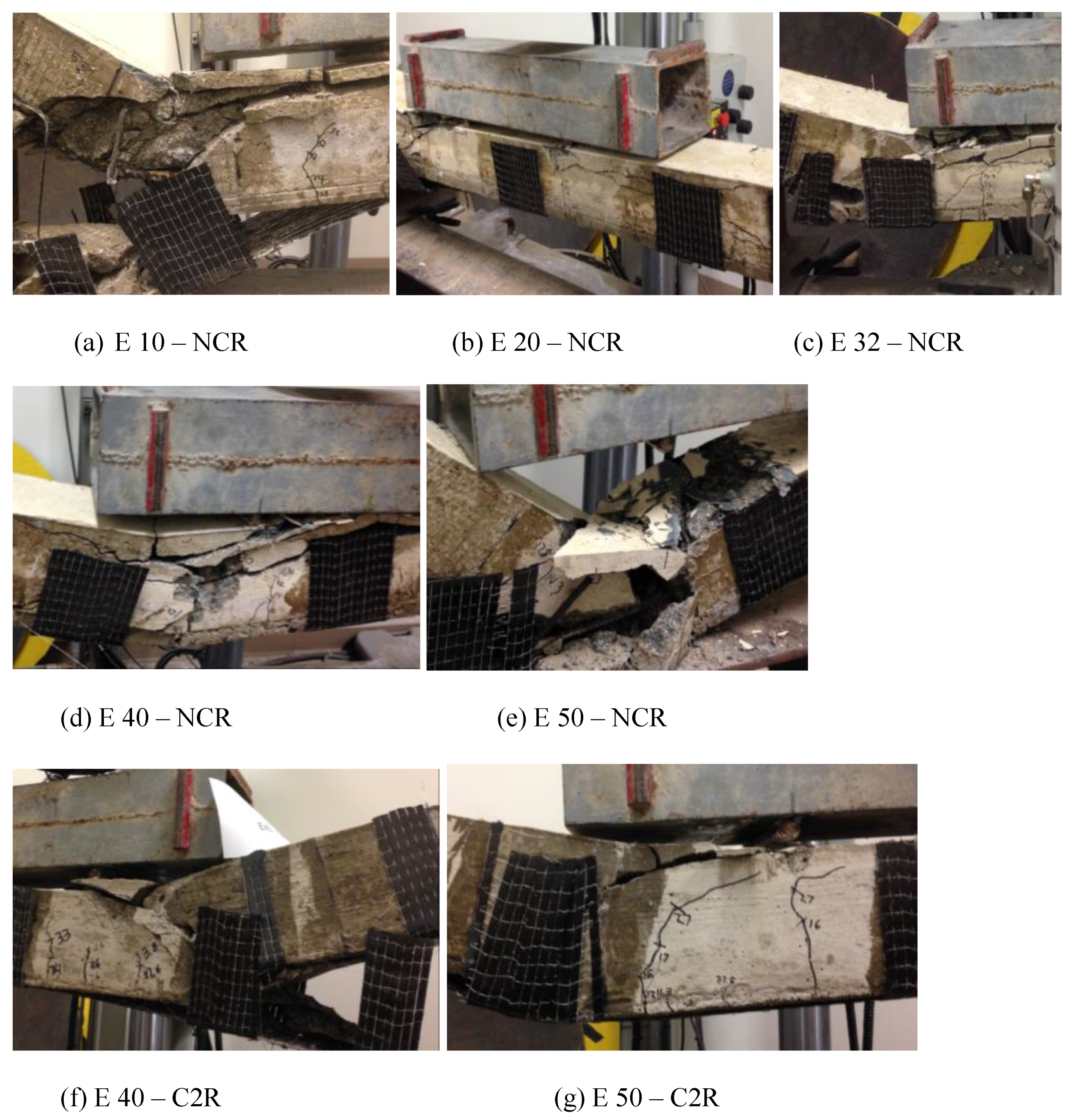
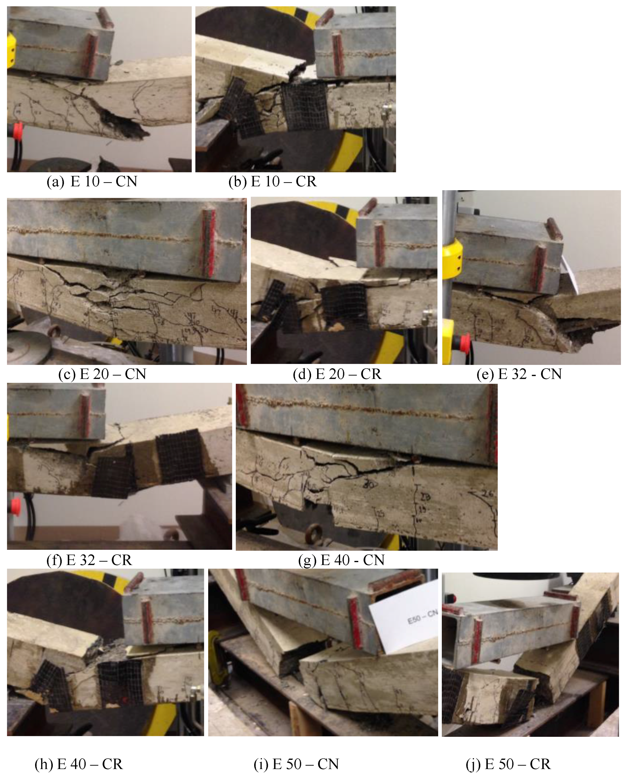
Figure 13.
Failure of beams with experimental corrosion.
Figure 13.
Failure of beams with experimental corrosion.
Figure 14.
Load-deflection of beams with 10% corrosion levels (No repair).
Figure 14.
Load-deflection of beams with 10% corrosion levels (No repair).
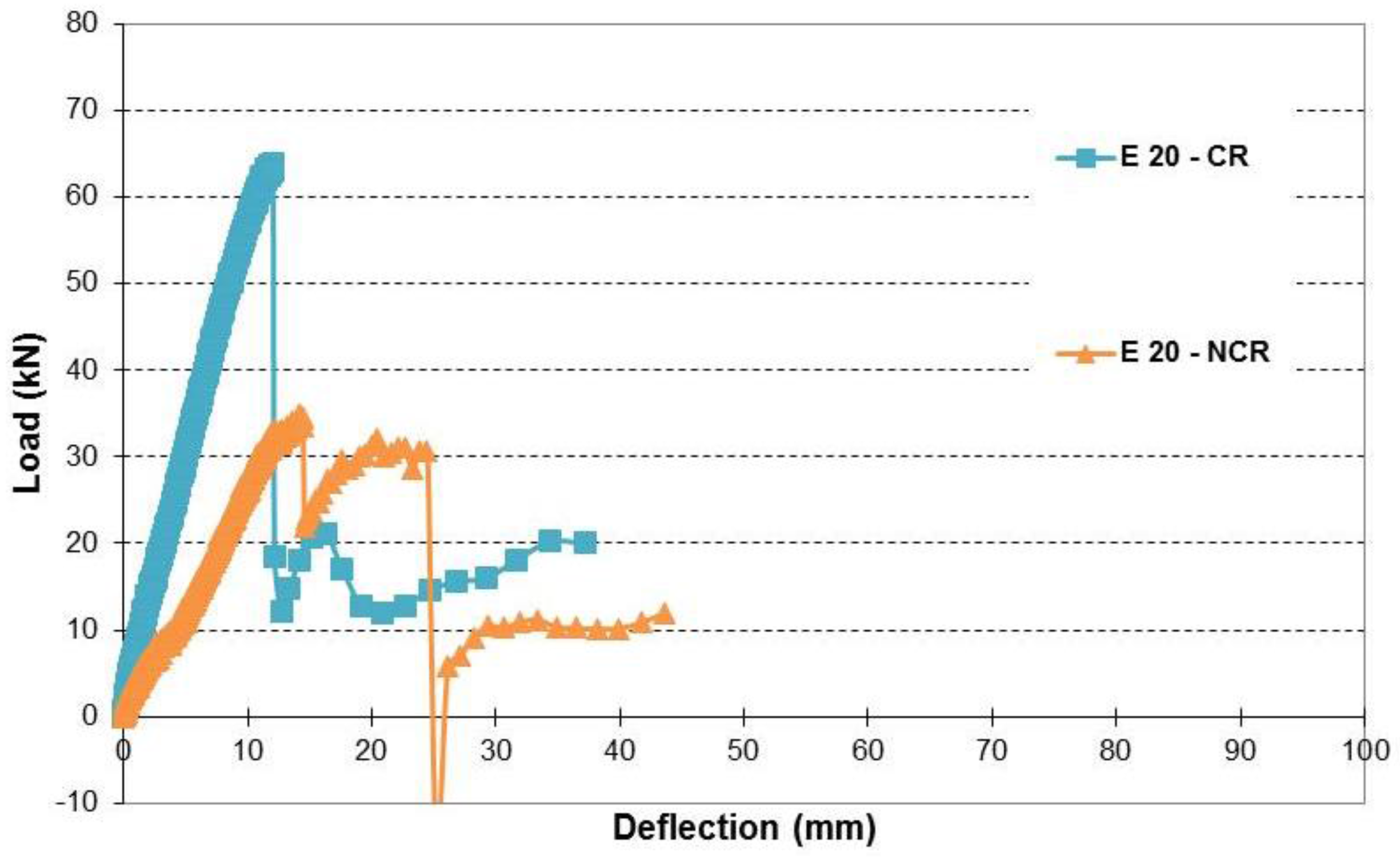
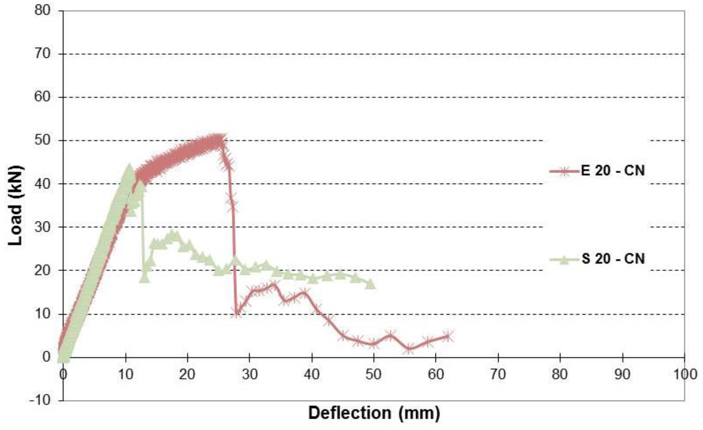
Figure 15.
Load-deflection of beams with 20% corrosion levels (No repair).
Figure 15.
Load-deflection of beams with 20% corrosion levels (No repair).
Figure 16.
Load-deflection of beams with 32% corrosion levels (No repair).
Figure 16.
Load-deflection of beams with 32% corrosion levels (No repair).
Figure 17.
Load-deflection of beams with 50% corrosion levels (No repair).
Figure 17.
Load-deflection of beams with 50% corrosion levels (No repair).
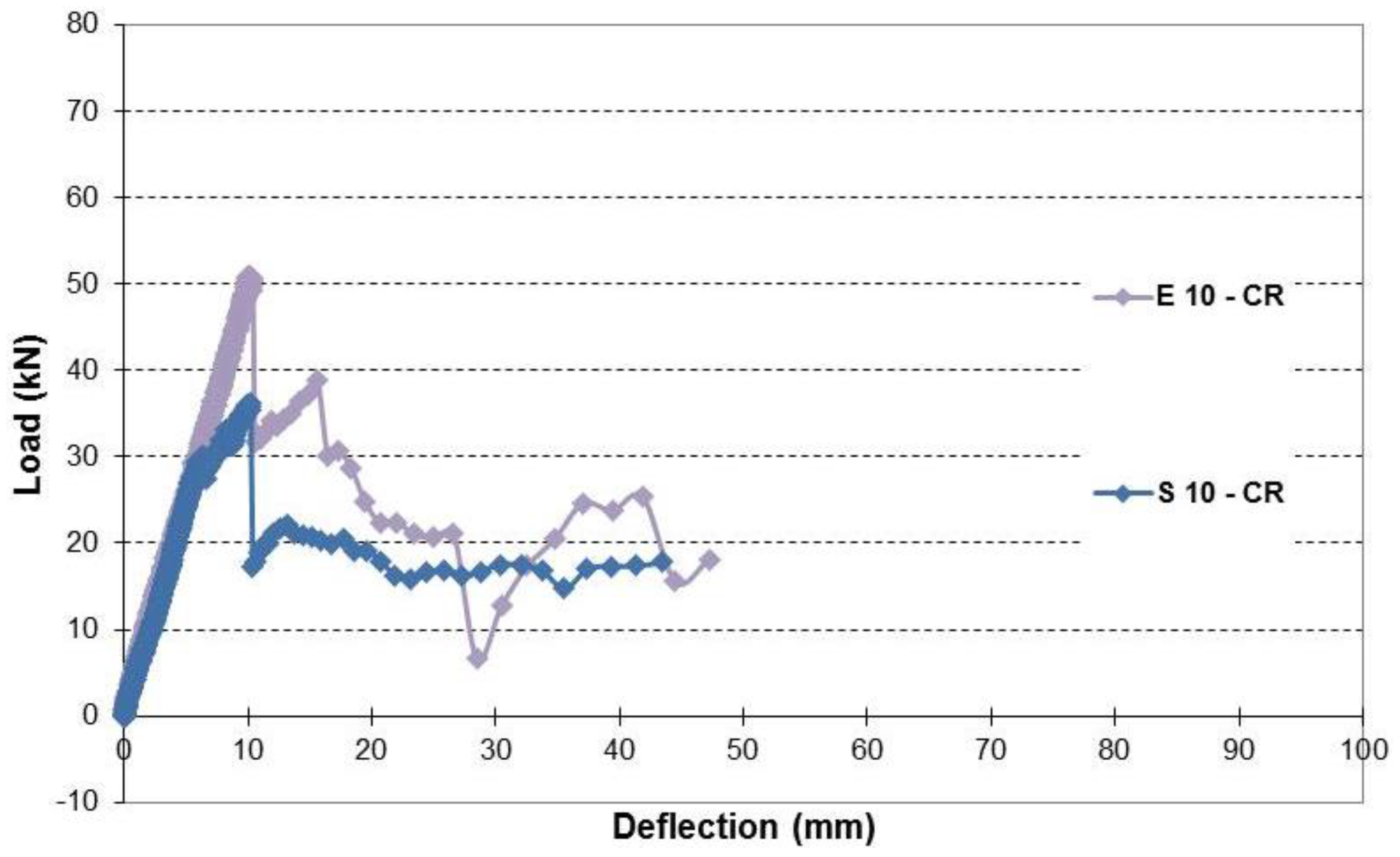
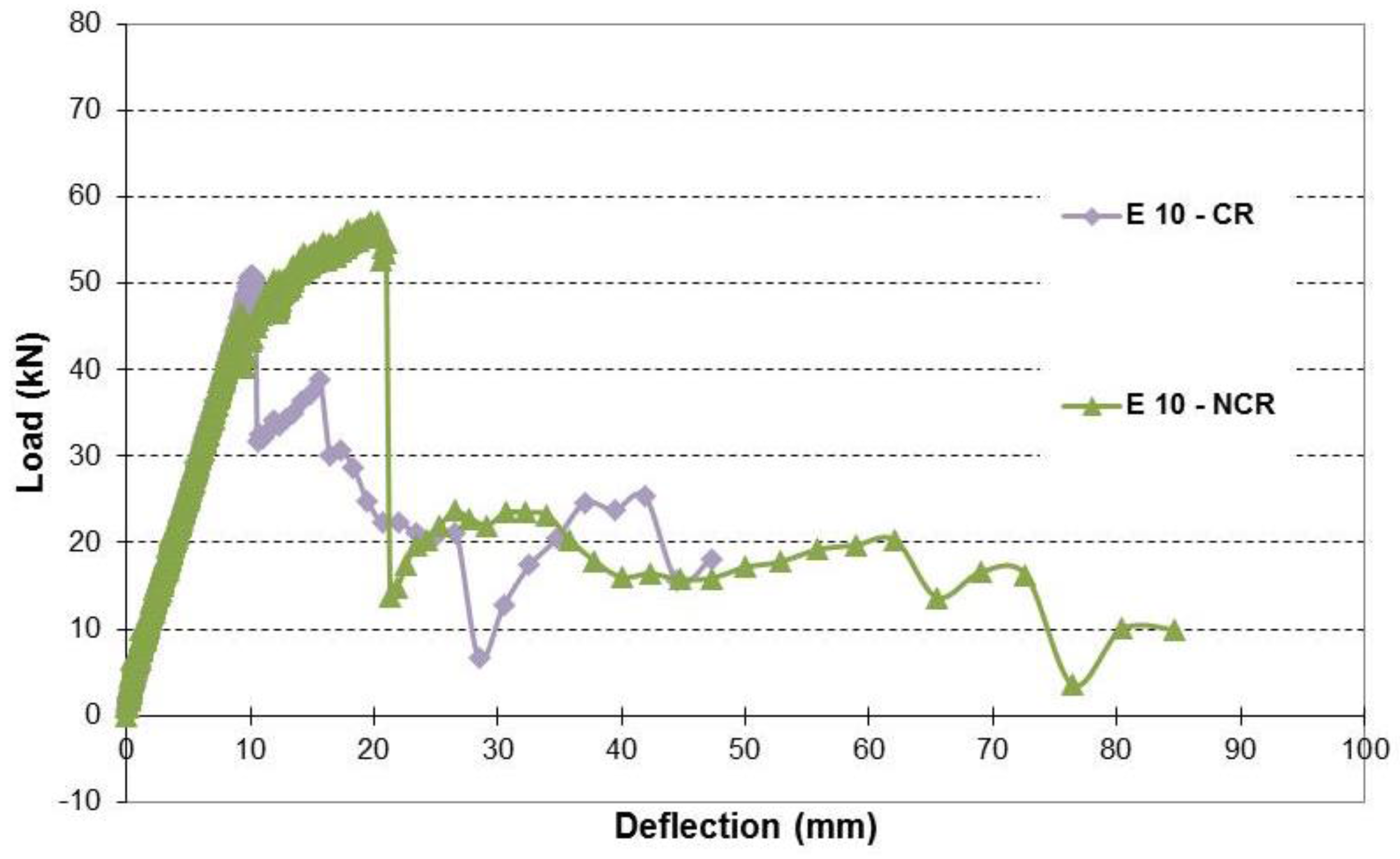
Figure 18.
Load-deflection of beams with 10% corrosion levels (Repaired).
Figure 18.
Load-deflection of beams with 10% corrosion levels (Repaired).
Figure 19.
Load-deflection of beams with 20% corrosion levels (Repaired).
Figure 19.
Load-deflection of beams with 20% corrosion levels (Repaired).
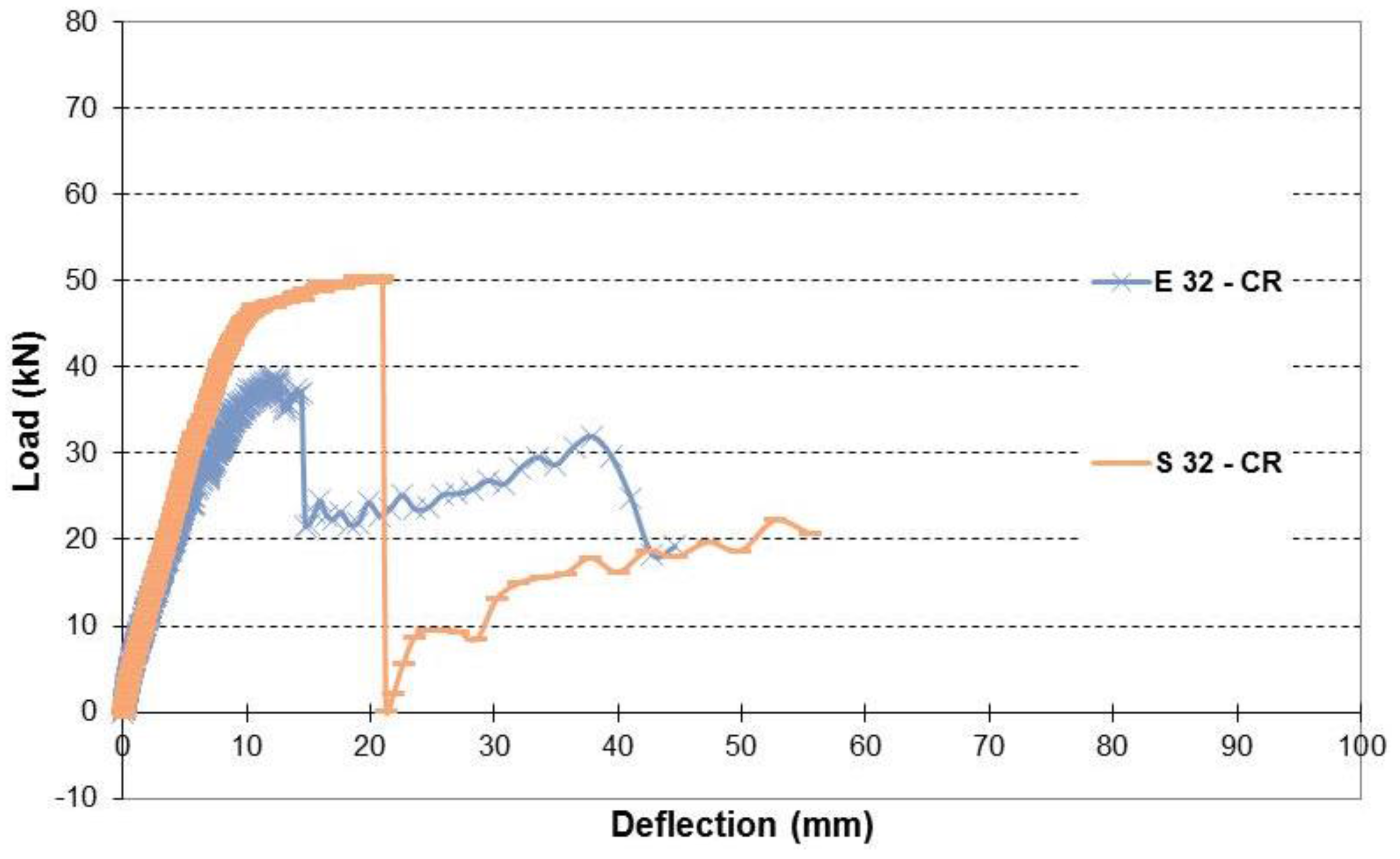
Figure 20.
Load-deflection of beams with 32% corrosion levels (Repaired).
Figure 20.
Load-deflection of beams with 32% corrosion levels (Repaired).
Figure 21.
Load-deflection of beams with 50% corrosion levels (Repaired).
Figure 21.
Load-deflection of beams with 50% corrosion levels (Repaired).
Figure 22.
Failure of beams without cover and repaired with double sheets.
Figure 22.
Failure of beams without cover and repaired with double sheets.
Figure 23.
Load-deflection relationship of repaired beams with 10% corrosion level with and without cover.
Figure 23.
Load-deflection relationship of repaired beams with 10% corrosion level with and without cover.
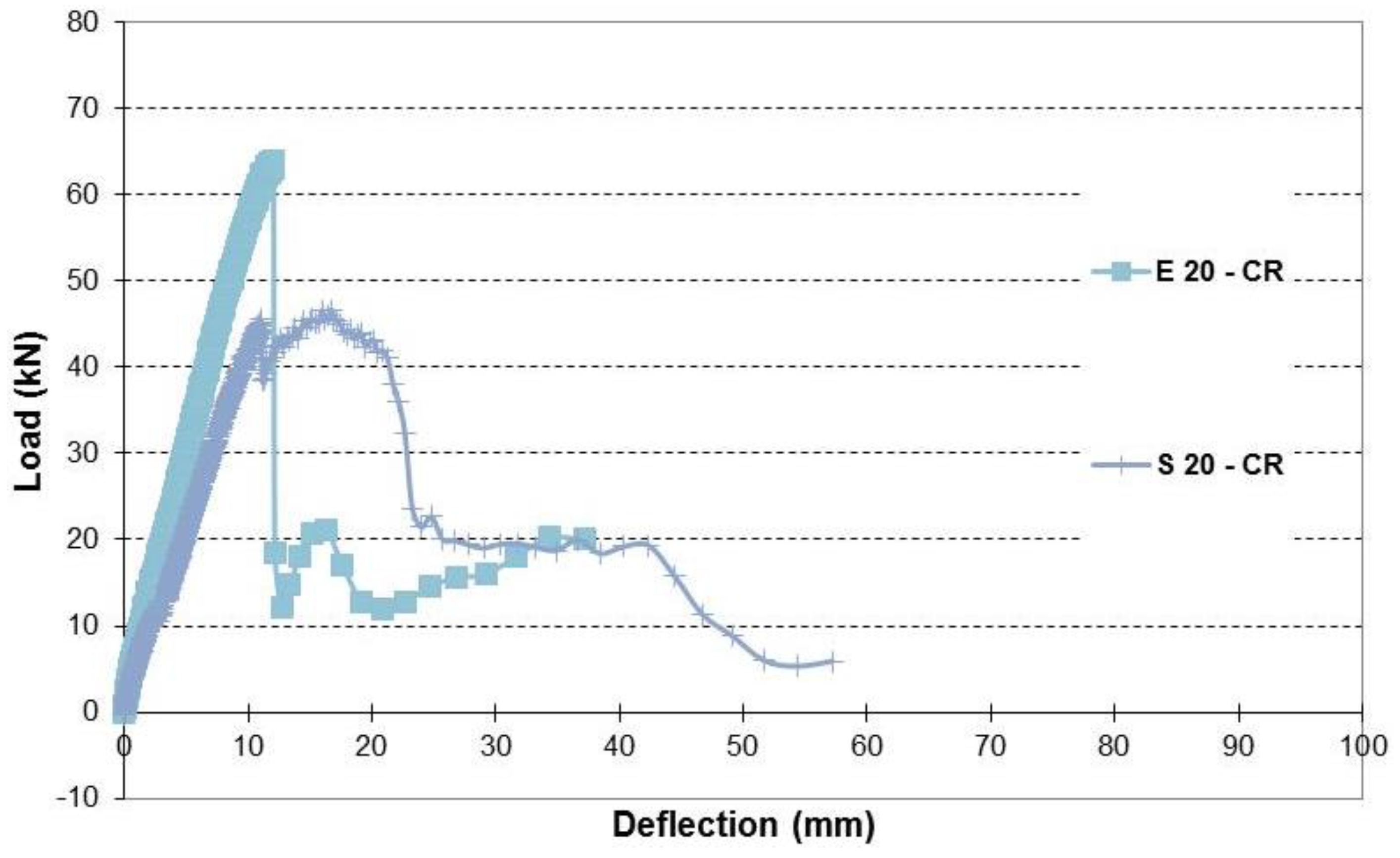
Figure 24.
Load-deflection relationship of repaired beams with 20% corrosion level with and without cover.
Figure 24.
Load-deflection relationship of repaired beams with 20% corrosion level with and without cover.
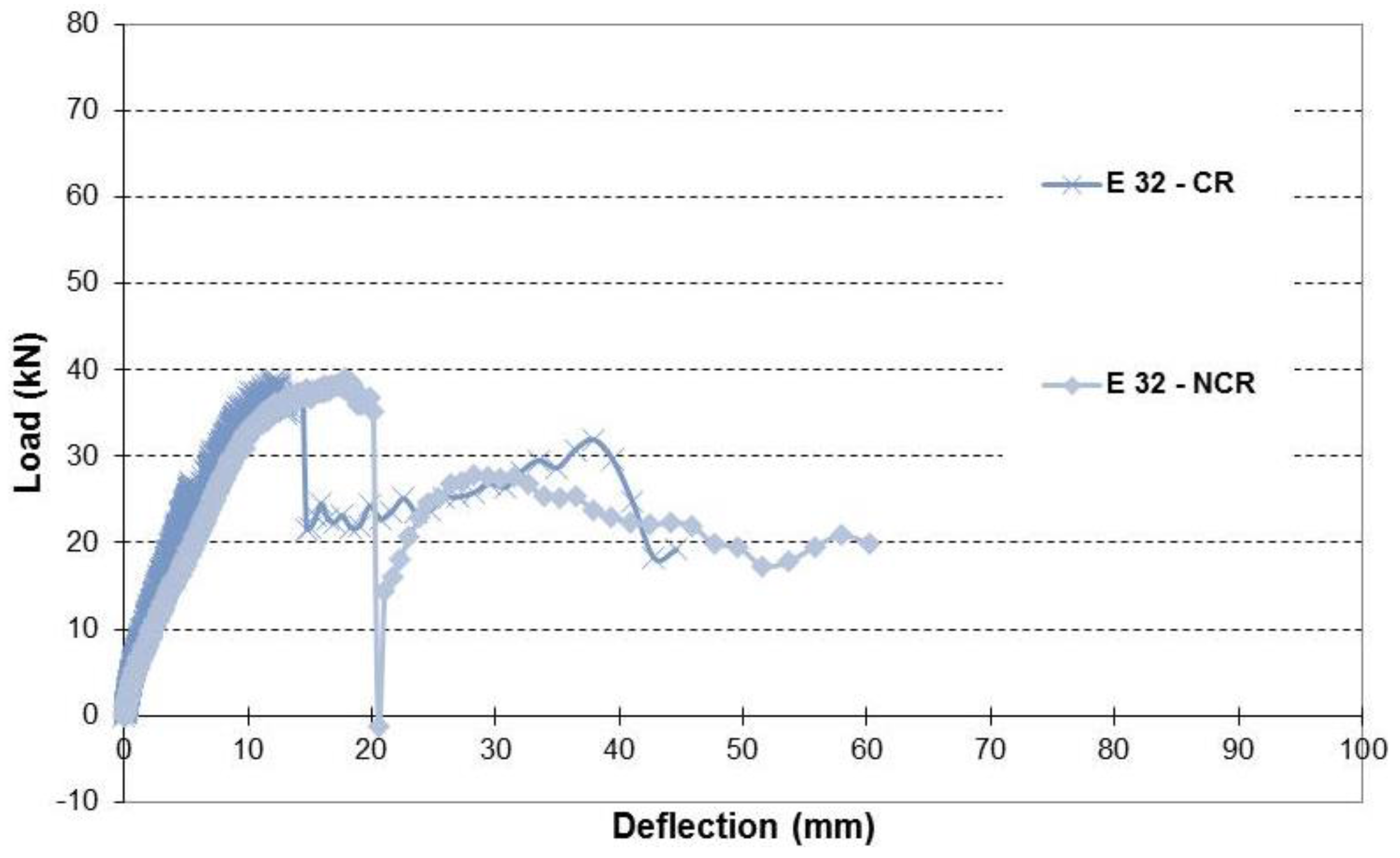
Figure 25.
Load-deflection relationship of repaired beams with 32% corrosion level with and without cover.
Figure 25.
Load-deflection relationship of repaired beams with 32% corrosion level with and without cover.
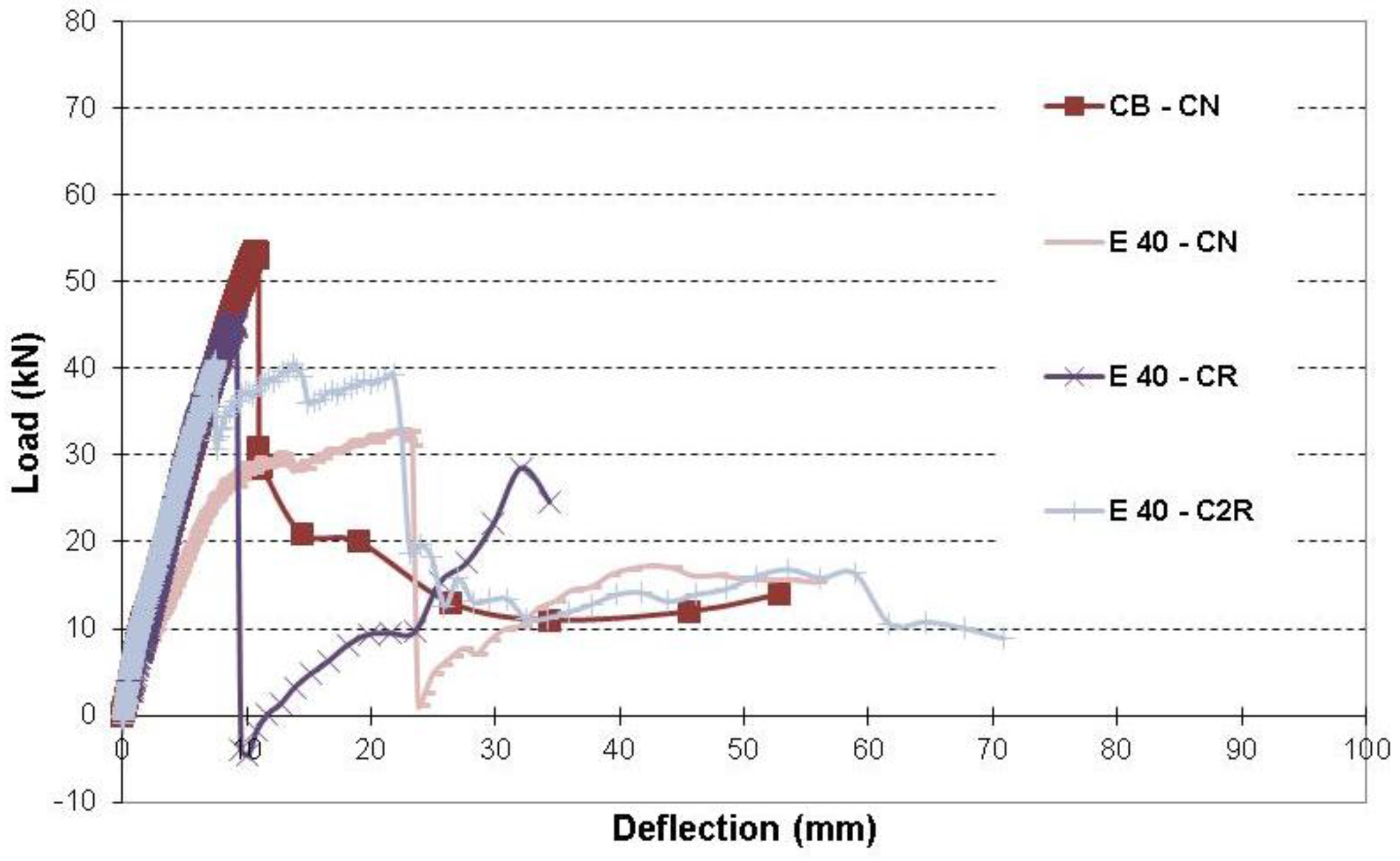
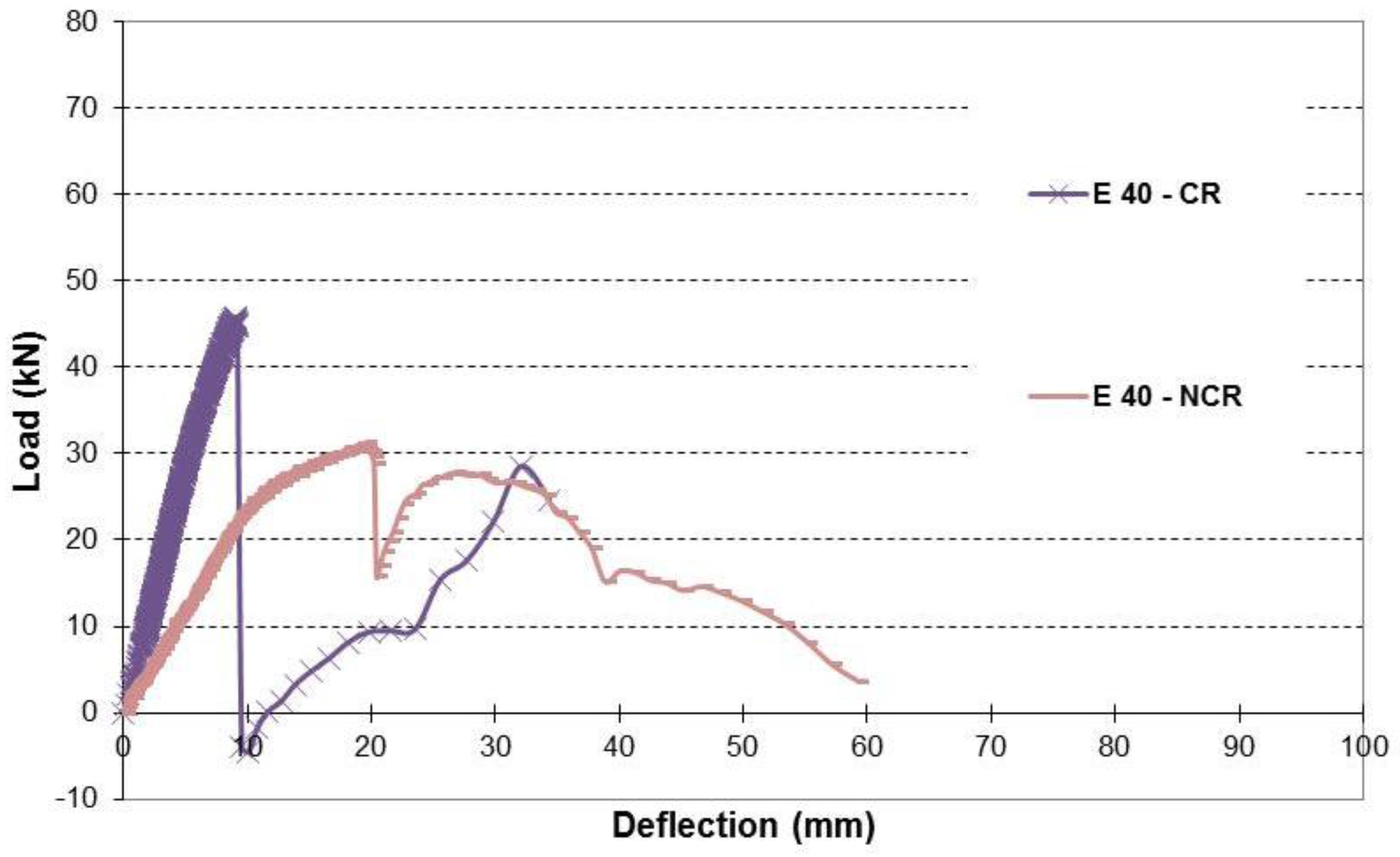
Figure 26.
Load-deflection relationship of repaired beams with 40% corrosion level with and without cover.
Figure 26.
Load-deflection relationship of repaired beams with 40% corrosion level with and without cover.
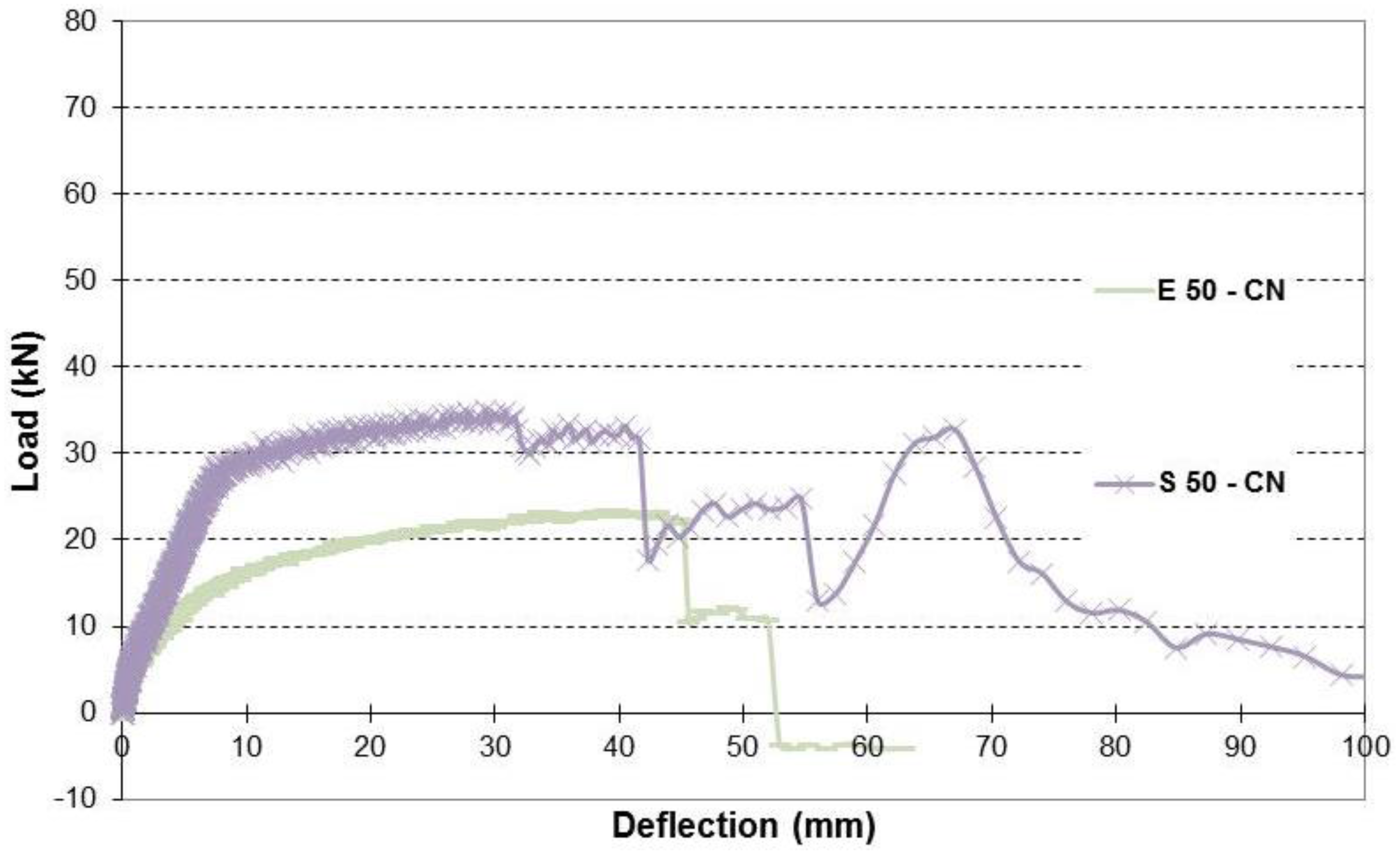
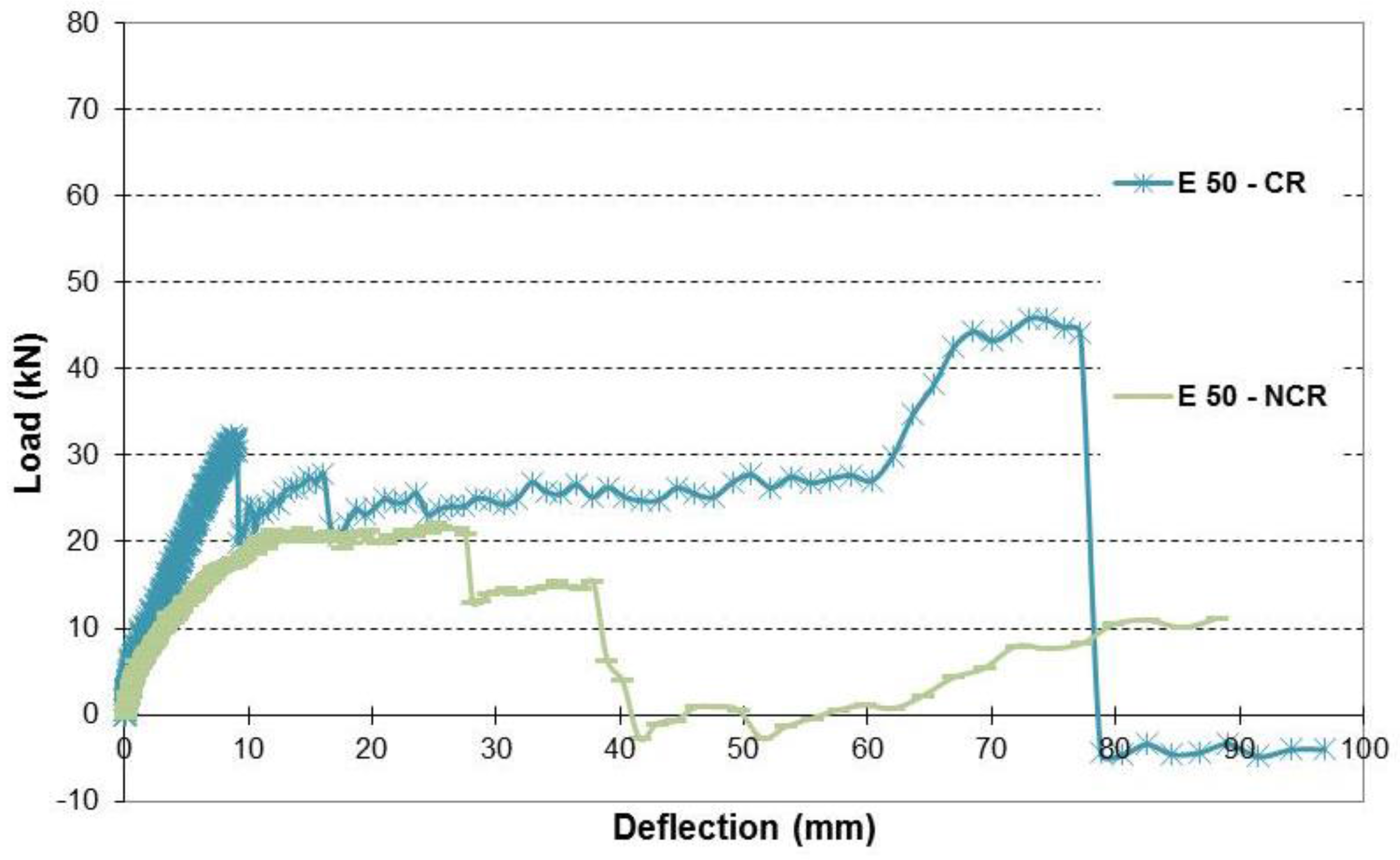
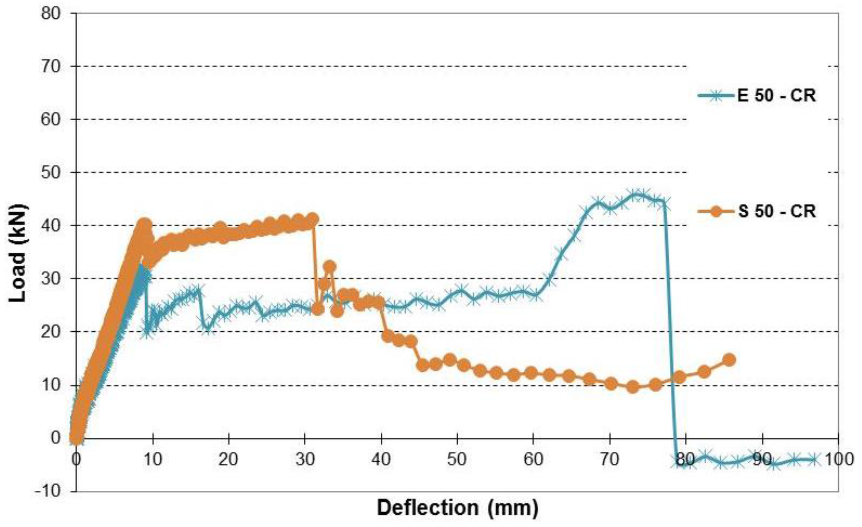
Figure 27.
Load-deflection relationship of repaired beams with 50% corrosion level with and without cover.
Figure 27.
Load-deflection relationship of repaired beams with 50% corrosion level with and without cover.
Figure 28.
Load-deflection of control beam and beams with 40% corrosion level.
Figure 28.
Load-deflection of control beam and beams with 40% corrosion level.
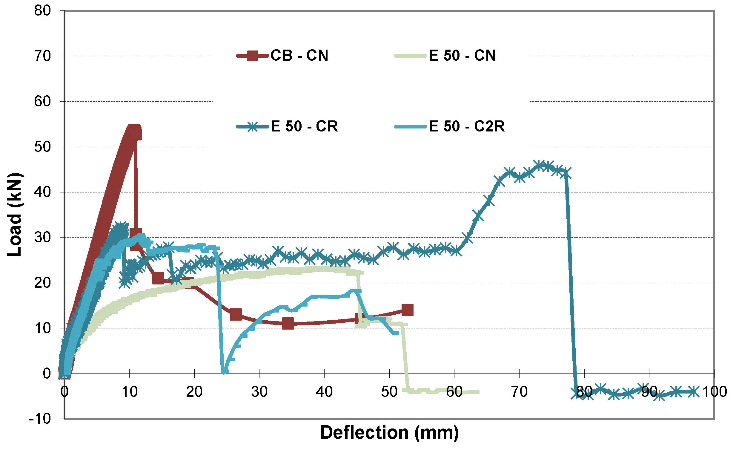
Figure 29.
Load-deflection of control beam and beams with 50% corrosion level.
Figure 29.
Load-deflection of control beam and beams with 50% corrosion level.
Table 1.
Mix design proportions. W: Water ; C: Cement.
Table 1.
Mix design proportions. W: Water ; C: Cement.
| W/C | 0.38 |
| Water (kg) | 144.0 |
| Cementitious Materials (kg) | Type I Portland Cement | 151.6 |
| Flyash | 113.7 |
| Slag Cement | 113.7 |
| Aggregates (kg) | RAP | 64.9 |
| Coarse | 584.2 |
| Fine | 625.0 |
Table 2.
Rebar diameter schedule for different corrosion levels. E: Experimental.
Table 2.
Rebar diameter schedule for different corrosion levels. E: Experimental.
| Beam | Rebar # | d0 (mm) | d1 (mm) | d2 (mm) | d3 (mm) | d4 (mm) | d5 (mm) | d6 (mm) | Corrosion Level (%) |
|---|
| E 10–CN 1 | 1 | 14.86 | 14.86 | 14.73 | 14.16 | 14.17 | 14.10 | 14.25 | 10.5 |
| 2 | 15.00 | 14.78 | 14.49 | 14.15 | 14.15 | 14.10 | 13.08 | 10.6 |
| E 10–CR 2 | 1 | 16.73 | 16.09 | 15.80 | 15.80 | 15.11 | 14.88 | 16.13 | 10 |
| 2 | 15.93 | 15.68 | 15.62 | 15.80 | 15.82 | 14.48 | 15.88 | 8.7 |
| E 10-NCR 3 | 1 | 15.28 | 15.56 | 14.96 | 14.73 | 14.59 | 14.57 | 13.59 | 8 |
| 2 | 15.77 | 15.25 | 14.77 | 14.57 | 14.68 | 14.26 | 13.93 | 10 |
| E 20–CN | 1 | 15.01 | 14.90 | 13.55 | 13.12 | 12.97 | 13.09 | 13.21 | 21 |
| 2 | 14.64 | 14.99 | 13.27 | 13.12 | 12.52 | 13.67 | 12.87 | 20.7 |
| E 20–CR | 1 | 16.18 | 15.67 | 13.92 | 13.51 | 13.46 | 13.16 | 11.96 | 19 |
| 2 | 15.79 | 14.99 | 14.43 | 13.59 | 13.28 | 13.42 | 13.34 | 18 |
| E 20-NCR | 1 | 15.10 | 14.97 | 14.47 | 13.60 | 13.14 | 12.40 | 13.45 | 19 |
| 2 | 15.13 | 15.07 | 14.83 | 13.64 | 12.76 | 13.08 | 14.26 | 19.8 |
| E 32–CN | 1 | 15.15 | 15.10 | 13.55 | 11.82 | 10.59 | 11.44 | 11.48 | 31.9 |
| 2 | 14.88 | 15.15 | 12.66 | 11.63 | 11.15 | 10.34 | 10.38 | 31.9 |
| E 32–CR | 1 | 14.78 | 14.58 | 12.27 | 12.24 | 11.68 | 11.28 | 11.80 | 31.8 |
| 2 | 15.20 | 14.06 | 12.83 | 12.52 | 11.95 | 11.33 | 11.84 | 31.6 |
| E 32-NCR | 1 | 15.02 | 14.71 | 13.32 | 12.87 | 11.77 | 11.15 | 12.03 | 31.8 |
| 2 | 15.05 | 14.77 | 13.58 | 13.39 | 11.06 | 10.67 | 10.36 | 32.5 |
| E 40–CN | 1 | 14.95 | 15.16 | 11.85 | 13.65 | 9.00 | 7.16 | 10.10 | 40.2 |
| 2 | 15.07 | 14.94 | 12.76 | 11.18 | 10.50 | 11.16 | 13.69 | 39.5 |
| E 40–CR | 1 | 16.59 | 14.05 | 12.27 | 11.54 | 11.34 | 9.60 | 10.33 | 39.5 |
| 2 | 15.90 | 15.15 | 12.78 | 11.65 | 9.69 | 9.11 | 12.14 | 40.6 |
| E 40-NCR | 1 | 14.82 | 13.36 | 11.58 | 10.95 | 10.46 | 10.62 | 11.37 | 39 |
| 2 | 14.77 | 13.40 | 12.31 | 11.11 | 9.87 | 10.67 | 11.54 | 40 |
| E 40-C2R 4 | 1 | 14.97 | 14.53 | 12.78 | 12.98 | 10.27 | 8.57 | 10.19 | 39.6 |
| 2 | 15.21 | 14.85 | 12.65 | 11.32 | 10.80 | 10.13 | 10.24 | 39 |
| E 50–CN | 1 | 15.23 | 14.11 | 9.04 | 8.23 | 9.08 | 10.62 | 12.87 | 49.3 |
| 2 | 15.16 | 15.04 | 7.75 | 6.74 | 10.68 | 10.41 | 12.76 | 49.3 |
| E 50–CR | 1 | 15.76 | 12.83 | 10.29 | 8.79 | 8.84 | 10.06 | 12.08 | 52 |
| 2 | 15.95 | 12.00 | 9.98 | 8.67 | 9.00 | 9.47 | 11.32 | 54 |
| E 50-NCR | 1 | 15.01 | 13.51 | 12.09 | 11.33 | 6.77 | 8.04 | 11.71 | 48 |
| 2 | 14.88 | 13.86 | 11.09 | 10.39 | 7.61 | 7.45 | 9.87 | 49.7 |
| E 50-C2R | 1 | 15.28 | 15.15 | 11.94 | 9.31 | 7.44 | 7.56 | 10.83 | 50.4 |
| 2 | 15.15 | 12.98 | 10.88 | 9.70 | 9.73 | 10.83 | 11.61 | 49.9 |
Table 3.
Simulated corrosion. S: Simulated. #: Size.
Table 3.
Simulated corrosion. S: Simulated. #: Size.
| Beams | Reinforcing Steel Used | Area (mm2) | % Simulated Corrosion Level | % Experimental Corrosion Level |
|---|
| S 10–CN & CR | 5 # 3 (9.525 mm in dia) | 354.84 | 11.3% | 10.0% |
| S 20–CN & CR | 2 # 4 (12.7 mm) + 1 # 3 (9.525 mm) | 329.03 | 17.8% | 20.0% |
| S 32–CN & CR | 1 # 4 (12.7 mm) + 2 # 3 (9.525 mm) | 270.97 | 32.2% | 32.0% |
| S 50–CN & CR | 3 # 3 (9.525 mm) | 212.90 | 46.8% | 50.0% |
Table 4.
Properties of carbon fiber reinforced polymer (CFRP) materials.
Table 4.
Properties of carbon fiber reinforced polymer (CFRP) materials.
| CFRP Properties | Dry Material Properties | Composite Material Properties |
|---|
| Tensile Strength (GPa) | 4.0 | 0.834 |
| Tensile Modulus (GPa) | 230.0 | 82.0 |
| Ultimate Elongation (%) | 1.7 | 1.0 |
Table 5.
Concrete compressive and tensile strength.
Table 5.
Concrete compressive and tensile strength.
| Age of Concrete (Days) | Compressive Strength | Tensile Strength |
|---|
| Strength Average (MPa) | Calculated Weibull Mean (MPa) | Strength Average (MPa) | Calculated Weibull Mean (MPa) |
|---|
| 3 | 4.53 | 4.68 | 0.66 | 0.68 |
| 7 | 10.93 | 11.17 | 1.58 | 1.60 |
| 14 | 17.78 | 18.34 | 2.51 | 2.53 |
| 28 | 19.15 | 20.88 | 2.87 | 2.93 |
Table 6.
Comparison between load capacity of all beams.
Table 6.
Comparison between load capacity of all beams.
| Beam | Load Capacity (kN) | Change % from CB–CN | Change % from S 10–CN | Change % from S 20–CN | Change % from S 32–CN | Change % from S 50–CN | Change % from E 10–CN | Change % from E 20–CN | Change % from E 32–CN | Change % from E 40–CN | Change % from E 50–CN | Change % from E 10–CR | Change % from E 20–CR | Change % from E 32–CR | Change % from E 40–CR | Change % from E 50–CR |
|---|
| CB–CN | 53.59 | 0 | | | | | | | | | | | | | | |
| S 10–CN | 31.25 | −41.70 | 0 | | | | −25.38 | | | | | | | | | |
| S 20–CN | 43.66 | −18.54 | | 0 | | | | −13.54 | | | | | | | | |
| S 32–CN | 38.8 | −27.60 | | | 0 | | | | 5.63 | | | | | | | |
| S 50–CN | 34.92 | −34.85 | | | | 0 | | | | | 49.56 | | | | | |
| S 10–CR | 36.16 | −32.52 | 15.74 | | | | | | | | | −29.01 | | | | |
| S 20–CR | 46.64 | −12.97 | | 6.84 | | | | | | | | | −27.12 | | | |
| S 32–CR | 50.53 | −5.72 | | | 30.21 | | | | | | | | | 30.18 | | |
| S 50–CR | 41.29 | −22.96 | | | | 18.25 | | | | | | | | | | 27.83 |
| E 10–CN | 41.87 | −21.87 | | | | | 0 | | | | | | | | | |
| E 20–CN | 50.49 | −5.78 | | | | | | 0 | | | | | | | | |
| E 32–CN | 36.73 | −31.46 | | | | | | | 0 | | | | | | | |
| E 40–CN | 32.9 | −38.61 | | | | | | | | 0 | | | | | | |
| E 50–CN | 23.35 | −56.44 | | | | | | | | | 0 | | | | | |
| E 10–CR | 50.94 | −4.96 | | | | | | | | | | 0 | | | | |
| E 20–CR | 64 | 19.41 | | | | | | | | | | | 0 | | | |
| E 32–CR | 38.81 | −27.58 | | | | | | | | | | | | 0 | | |
| E 40–CR | 45.82 | −14.50 | | | | | | | | 39.27 | | | | | 0 | |
| E 50–CR | 32.3 | −39.73 | | | | | | | | | 38.35 | | | | | 0 |
| E 10–NCR | 57.22 | 6.76 | | | | | | | | | | 12.33 | | | | |
| E 20–NCR | 34.96 | −34.76 | | | | | | | | | | | −45.37 | | | |
| E 32–NCR | 38.97 | −27.28 | | | | | | | | | | | | 0.40 | | |
| E 40–NCR | 31.23 | −41.74 | | | | | | | | | | | | | −31.85 | |
| E 50–NCR | 22.2 | −58.57 | | | | | | | | | | | | | | −31.26 |
| E 40–C2R | 40.8 | −23.86 | | | | | | | | 24.02 | | | | | | |
| E 50–C2R | 30.56 | −42.97 | | | | | | | | | 30.91 | | | | | |
Table 7.
Failure description of control beam and beams with simulated corrosion.
Table 7.
Failure description of control beam and beams with simulated corrosion.
| Beam | Mode of Failure |
|---|
| CB–CN | Splitting cracking in the clamped side, crushing in top concrete, and debonding cracking in the concrete cover in the clamped side. |
| S 10–CN | Splitting crack on the clamped side at 30.5 kN and crushing of the top concrete. |
| S 10–CR | Deboning of CFRP, rupture of first U in the clamped side, splitting crack on the clamped side, and crushing of concrete. |
| S 20–CN | Splitting crack on the clamped side, debonding crack in the concrete cover, and crushing of the top concrete. |
| S 20–CR | Debonding of CFRP, splitting cracks close to the unclamped side, and crushing of top concrete. |
| S 32–CN | Two splitting cracks; one on each side, crushing of concrete, and debonding cracking in the concrete cover on the clamped side. |
| S 32–CR | Rupture of bottom CFRP sheet on the clamped side, debonding of CFRP, splitting cracking in the unclamped side, and crushing of top concrete. |
| S 50–CN | Two splitting cracks; one on each side and crushing of top concrete. |
| S 50–CR | Debonding of CFRP, splitting cracking in the clamped side, rupture in the first U on the clamped side, and crushing of top concrete. |
Table 8.
Failure description of beams with experimental corrosion.
Table 8.
Failure description of beams with experimental corrosion.
| Beam | Mode of Failure |
|---|
| E 10–CN | Splitting cracking in the clamped side and crushing of top concrete. |
| E 10–CR | Debonding of CFRP, splitting cracking in the unclamped side, crushing in top concrete, and rupture in the first U in the unclamped side. |
| E 20–CN | Two splitting cracks; one on each side, crack at mid-span, and crushing of top concrete. |
| E 20–CR | Debonding of CFRP, splitting cracking in the unclamped side, and crushing in top concrete. |
| E 32–CN | Two splitting cracks; one on each side, crushing in top concrete, and peeling failure in concrete cover in the clamped side. |
| E 32–CR | Debonding of CFRP, splitting cracking in the clamped side, crushing in top concrete, and rupture of second U on the clamped side. |
| E 40–CN | Two splitting cracks; one on each side, and crushing in top concrete. |
| E 40–CR | Debonding of CFRP, splitting crack in the unclamped side, rupture of the first and second U in the unclamped side. |
| E 50–CN | Rupture of rebars and crushing in top concrete. |
| E 50–CR | Debonding of CFRP; rupture of bottom CFRP sheet, middle U, and first U on the clamped side; crushing in top concrete; and rupture of rebars. |
Table 9.
Failure description of beams without cover and repaired with double sheets.
Table 9.
Failure description of beams without cover and repaired with double sheets.
| Beam | Mode of Failure |
|---|
| E 10–NCR | Peeling failure of concrete cover, splitting crack in the unclamped side, rupture of the first and second U on the unclamped side, and crushing in top concrete. |
| E 20–NCR | Two splitting cracks; one on each side, debonding of CFRP, peeling failure of concrete cover, and crushing of top concrete. |
| E 32–NCR | Debonding of CFRP, splitting cracking in the unclamped side, rupture of the first U in the unclamped side, and crushing of the top concrete. |
| E 40–NCR | Debonding of CFRP, splitting crack on the unclamped side, crushing of top concrete, and a slight peeling failure of concrete cover. |
| E 50–NCR | Debonding of CFRP, rupture of first U on the unclamped side, splitting crack on the unclamped side, rupture of rebars, and crushing of top concrete. |
| E 40–C2R | Debonding of CFRP, rupture of the first and second U on the clamped side, splitting cracking in the clamped side, and crushing of top concrete. |
| E 50–C2R | Debonding of CFRP, rupture of the first U on the clamped side and second U on the unclamped side, splitting cracking in the unclamped side, and crushing of top concrete. |


