
Concrete-Filled-Large Deformable FRP Tubular Columns under Axial Compressive Loading

Abstract
:1. Introduction
2. Finite Element Model Validation

| Cylinder Label | Diameter (mm) X Height (mm) | (MPa) | FRP Type | No. of Layers | Total Thickness (mm) |
|---|---|---|---|---|---|
| PEN-600-I | 150 × 300 | 39.2 | PEN-600 | One | 0.85 |
| PEN-600-II | Two | 1.70 | |||
| PEN-600-III | Three | 2.54 | |||
| PET-600-I | 32.5 | PET-600 | One | 0.84 | |
| PET-600-II | Two | 1.68 | |||
| PET-600-III | Three | 2.52 | |||
| PET-900-I | 39.2 | PET-900 | One | 1.26 | |
| PET-900-II | Two | 2.52 | |||
| PET-900-III | Three | 3.79 |
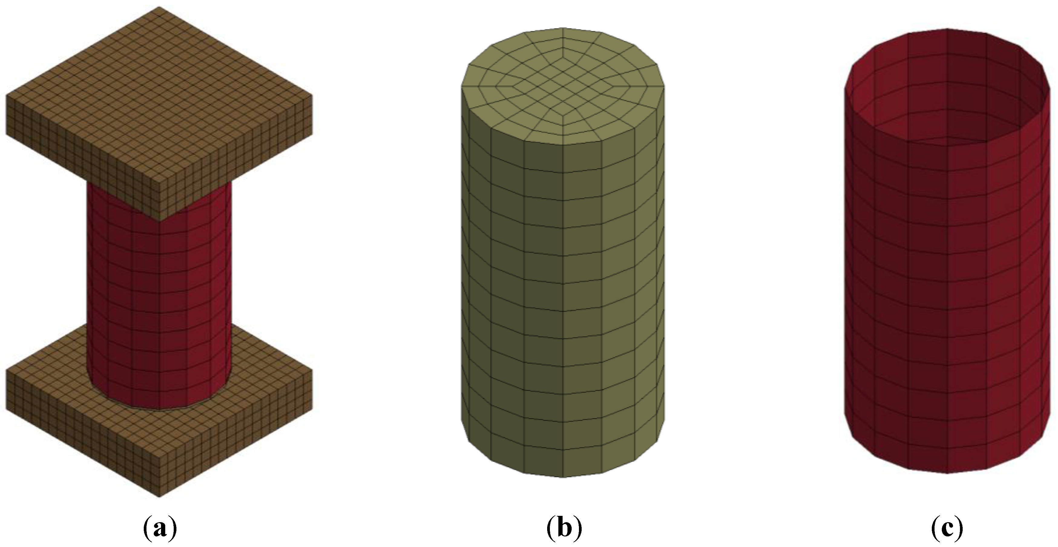
2.1. Geometry

2.2. Concrete Material Model
2.3. FRP Material Model
| FRP Type | Ef1 (GPa) | Ef2 (GPa) | Tensile Strength (MPa) | Rupture Strain (%) |
|---|---|---|---|---|
| PET-FRP | 17.9 | 8.3 | 750 | 8.7 |
| PEN-FRP | 27.0 | 12.0 | 760 | 6.3 |
| Glass-FRP | 26.1 | – | 575 | 2.2 |
| Carbon-FRP | 95.8 | – | 986 | 1.0 |
2.4. Loading and Boundary Conditions
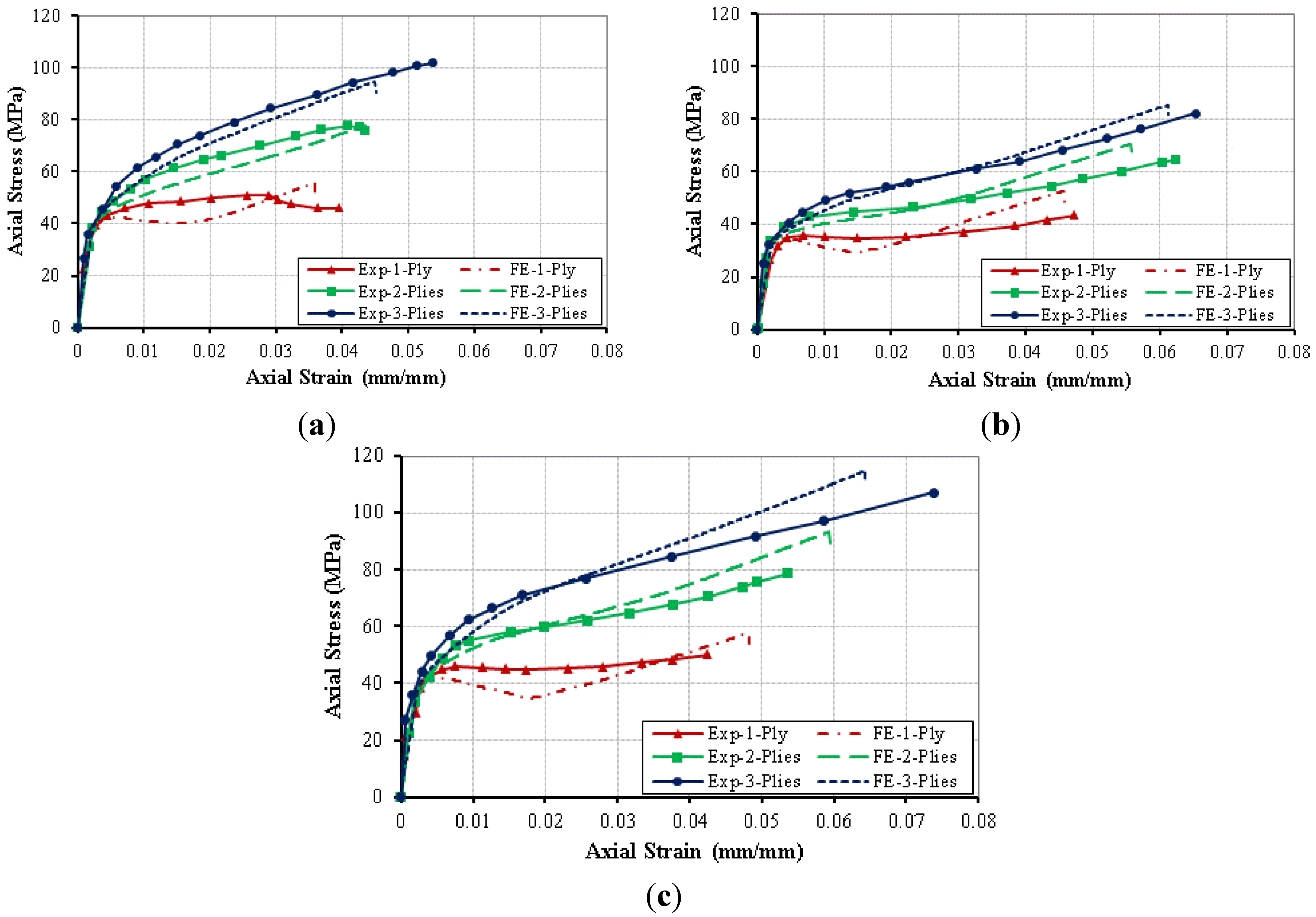
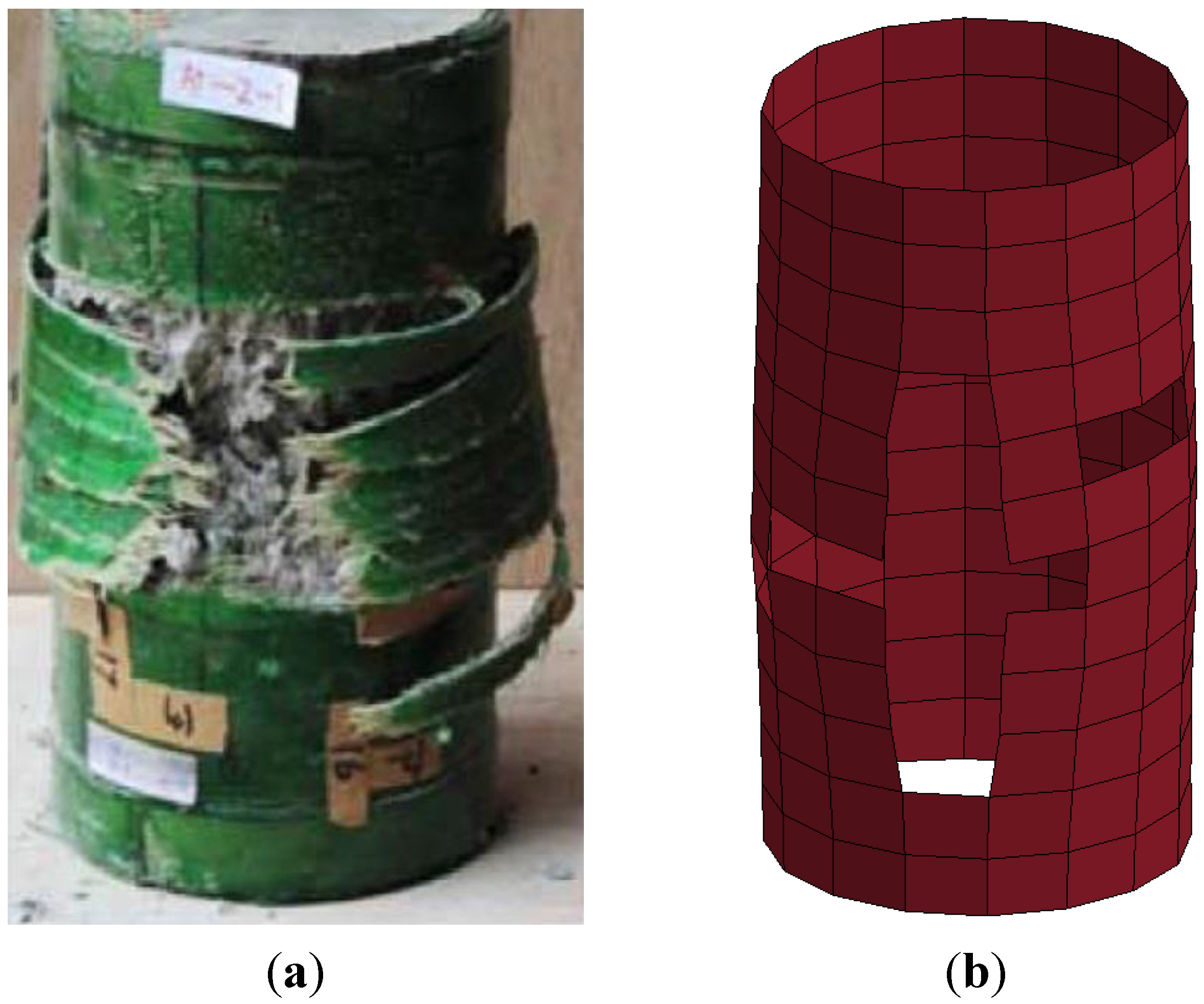
2.5. Validation Results


3. Parametric Study
| Parameter | Col. Label | Diameter (mm) | Height (mm) | Aspect Ratio | LRS-FRP Thickness (mm) | Traditional FRP Thickness (mm) | (MPa) | Conf. Ratio | Dilation Parameter |
|---|---|---|---|---|---|---|---|---|---|
| PET-FRP | C0 | 150 | 300 | 2 | 3.4 | 0 | 27.6 | 1.20 | 0.29 |
| C1 | 150 | 300 | 2 | 2.97 | 0 | 27.6 | 1.05 | 0.33 | |
| C2 | 150 | 300 | 2 | 2.55 | 0 | 27.6 | 0.90 | 0.37 | |
| C3 | 150 | 300 | 2 | 2.13 | 0 | 27.6 | 0.75 | 0.41 | |
| C4 | 150 | 300 | 2 | 1.7 | 0 | 27.6 | 0.60 | 0.46 | |
| C5 | 150 | 300 | 2 | 1.28 | 0 | 27.6 | 0.45 | 0.52 | |
| C6 | 150 | 300 | 2 | 0.85 | 0 | 27.6 | 0.30 | 0.60 | |
| PEN-FRP | C7 | 150 | 300 | 2 | 3.1 | 0 | 27.6 | 1.20 | 0.23 |
| C8 | 150 | 300 | 2 | 2.7 | 0 | 27.6 | 1.05 | 0.26 | |
| C9 | 150 | 300 | 2 | 2.32 | 0 | 27.6 | 0.90 | 0.30 | |
| C10 | 150 | 300 | 2 | 1.92 | 0 | 27.6 | 0.75 | 0.34 | |
| C11 | 150 | 300 | 2 | 1.54 | 0 | 27.6 | 0.60 | 0.40 | |
| C12 | 150 | 300 | 2 | 1.15 | 0 | 27.6 | 0.45 | 0.47 | |
| C13 | 150 | 300 | 2 | 0.78 | 0 | 27.6 | 0.30 | 0.55 | |
| GLASS-FRP | C14 | 150 | 300 | 2 | 0 | 4.33 | 27.6 | 1.20 | −0.17 |
| C15 | 150 | 300 | 2 | 0 | 3.8 | 27.6 | 1.05 | −0.14 | |
| C16 | 150 | 300 | 2 | 0 | 3.25 | 27.6 | 0.90 | −0.11 | |
| C17 | 150 | 300 | 2 | 0 | 2.7 | 27.6 | 0.75 | −0.08 | |
| C18 | 150 | 300 | 2 | 0 | 2.15 | 27.6 | 0.60 | −0.03 | |
| C19 | 150 | 300 | 2 | 0 | 1.62 | 27.6 | 0.45 | 0.02 | |
| C20 | 150 | 300 | 2 | 0 | 1.07 | 27.6 | 0.30 | 0.10 | |
| CARBON-FRP | C21 | 150 | 300 | 2 | 0 | 2.6 | 27.6 | 1.20 | −0.32 |
| C22 | 150 | 300 | 2 | 0 | 2.27 | 27.6 | 1.05 | −0.30 | |
| C23 | 150 | 300 | 2 | 0 | 1.94 | 27.6 | 0.90 | −0.27 | |
| C24 | 150 | 300 | 2 | 0 | 1.62 | 27.6 | 0.75 | −0.23 | |
| C25 | 150 | 300 | 2 | 0 | 1.3 | 27.6 | 0.60 | −0.19 | |
| C26 | 150 | 300 | 2 | 0 | 0.98 | 27.6 | 0.45 | −0.13 | |
| C27 | 150 | 300 | 2 | 0 | 0.65 | 27.6 | 0.30 | −0.05 | |
| PET/Glass (inside/outside) | C28 | 150 | 300 | 2 | 2.55 | 1.07 | 27.6 | 1.20 | 0.47 |
| C29 | 150 | 300 | 2 | 1.7 | 2.15 | 27.6 | 1.20 | 0.43 | |
| C30 | 150 | 300 | 2 | 0.85 | 3.25 | 27.6 | 1.20 | 0.48 | |
| Glass/PET (inside/outside) | C31 | 150 | 300 | 2 | 2.55 | 1.07 | 27.6 | 1.20 | 0.47 |
| C32 | 150 | 300 | 2 | 1.7 | 2.15 | 27.6 | 1.20 | 0.43 | |
| C33 | 150 | 300 | 2 | 0.85 | 3.25 | 27.6 | 1.20 | 0.48 | |
| PET/Carbon (inside/outside) | C34 | 150 | 300 | 2 | 2.55 | 0.65 | 27.6 | 1.20 | 0.31 |
| C35 | 150 | 300 | 2 | 1.7 | 1.3 | 27.6 | 1.20 | 0.27 | |
| C36 | 150 | 300 | 2 | 0.85 | 1.95 | 27.6 | 1.20 | 0.33 | |
| Carbon/PET (inside/outside) | C37 | 150 | 300 | 2 | 2.55 | 0.65 | 27.6 | 1.20 | 0.31 |
| C38 | 150 | 300 | 2 | 1.7 | 1.3 | 27.6 | 1.20 | 0.27 | |
| C39 | 150 | 300 | 2 | 0.85 | 1.95 | 27.6 | 1.20 | 0.33 | |
| Concrete Strength () | C40 | 150 | 300 | 2 | 5.1 | 0 | 41.4 | 1.20 | 0.29 |
| C41 | 150 | 300 | 2 | 6.8 | 0 | 55.2 | 1.20 | 0.29 | |
| C42 | 150 | 300 | 2 | 8.5 | 0 | 69 | 1.20 | 0.29 | |
| C43 | 150 | 300 | 2 | 10.2 | 0 | 82.8 | 1.20 | 0.29 | |
| Column size | C44 | 200 | 400 | 2 | 4.55 | 0 | 27.6 | 1.20 | 0.29 |
| C45 | 300 | 600 | 2 | 6.8 | 0 | 27.6 | 1.20 | 0.29 | |
| C46 | 1500 | 3000 | 2 | 34 | 0 | 27.6 | 1.20 | 0.29 | |
| Column aspect ratio | C47 | 300 | 1500 | 5 | 6.8 | 0 | 27.6 | 1.20 | 0.29 |
| C48 | 300 | 3000 | 10 | 6.8 | 0 | 27.6 | 1.20 | 0.29 |
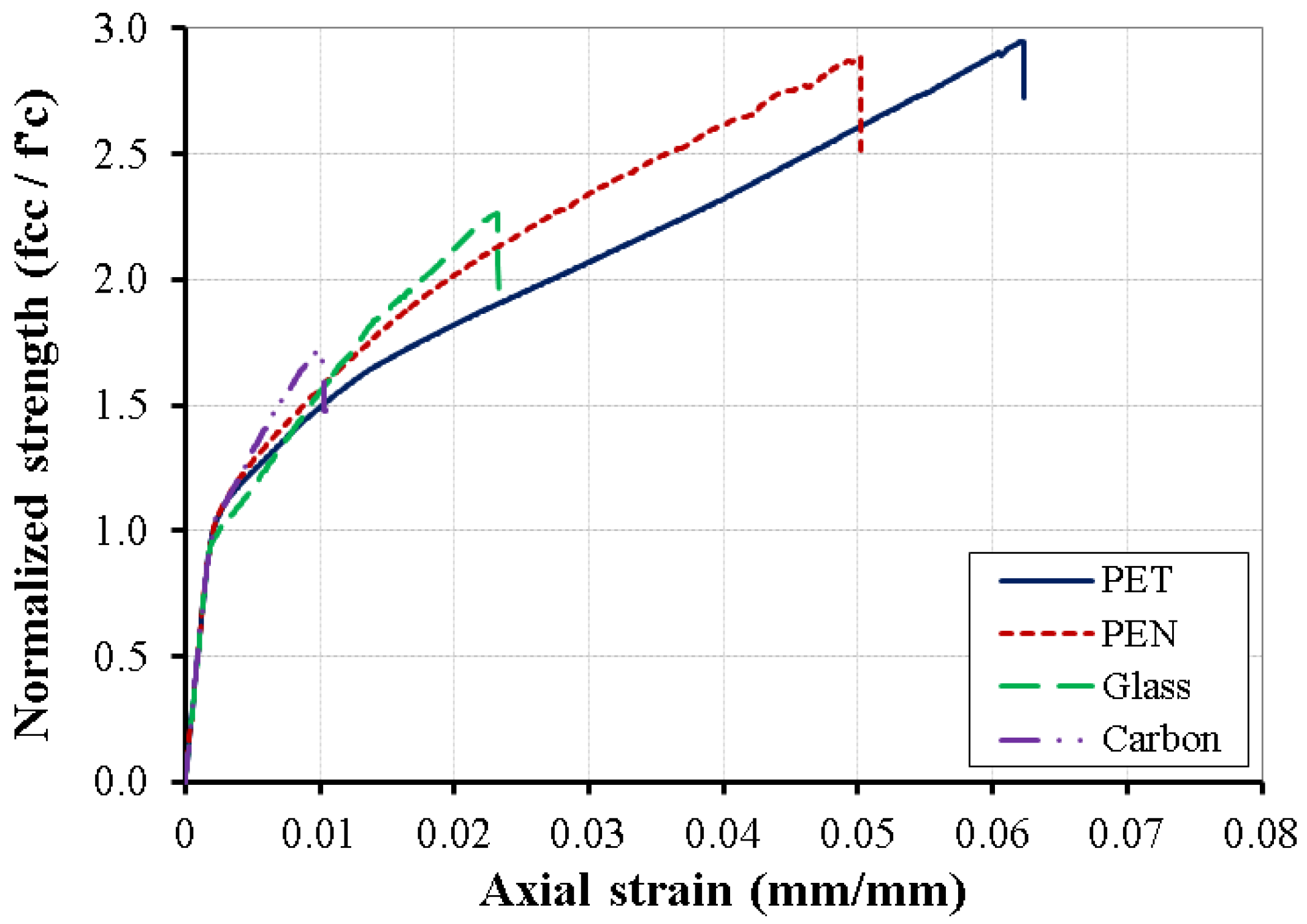
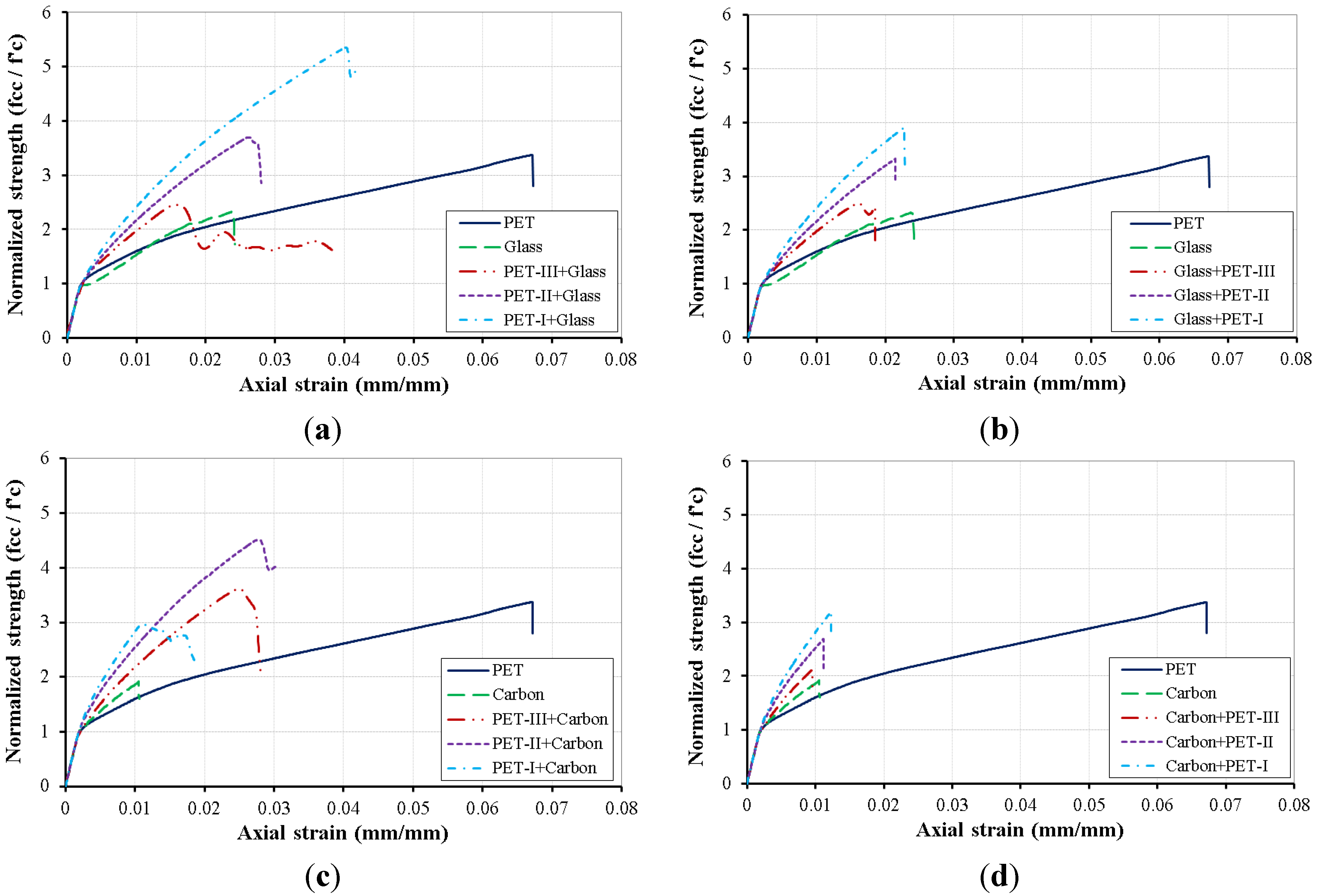
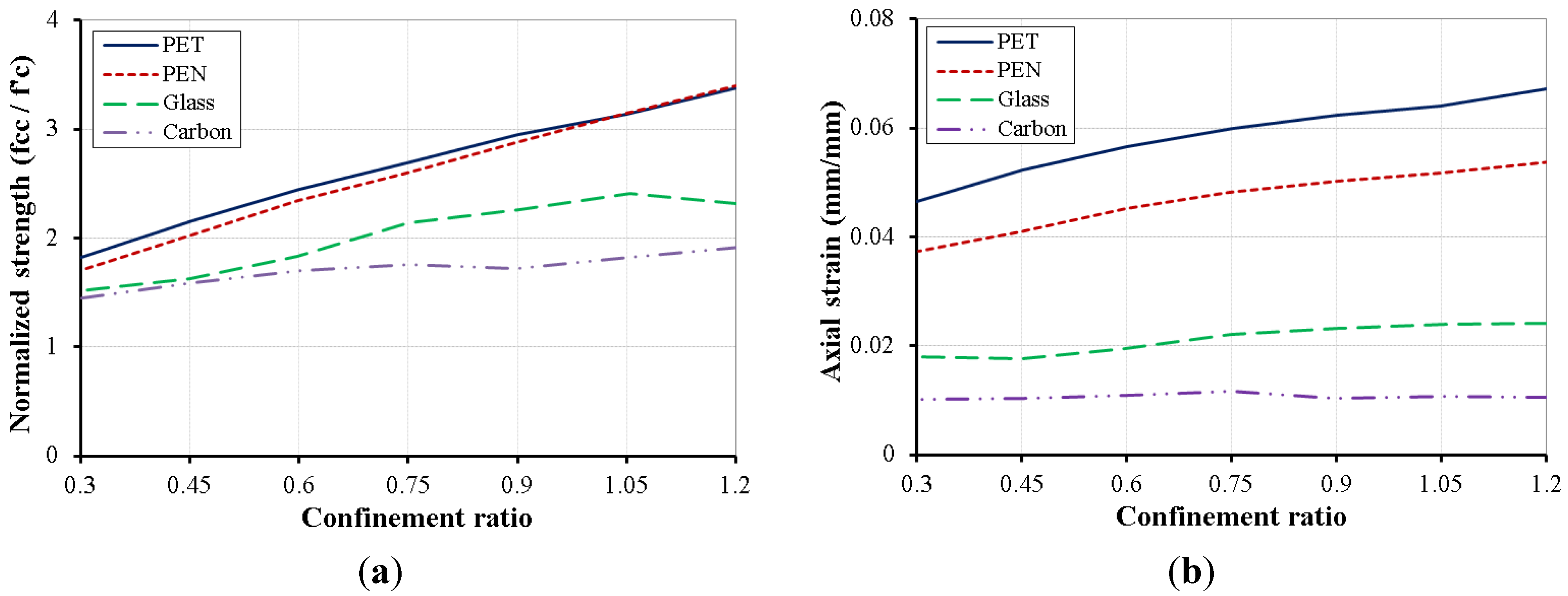
3.1. LRS-FRP versus Traditional FRP


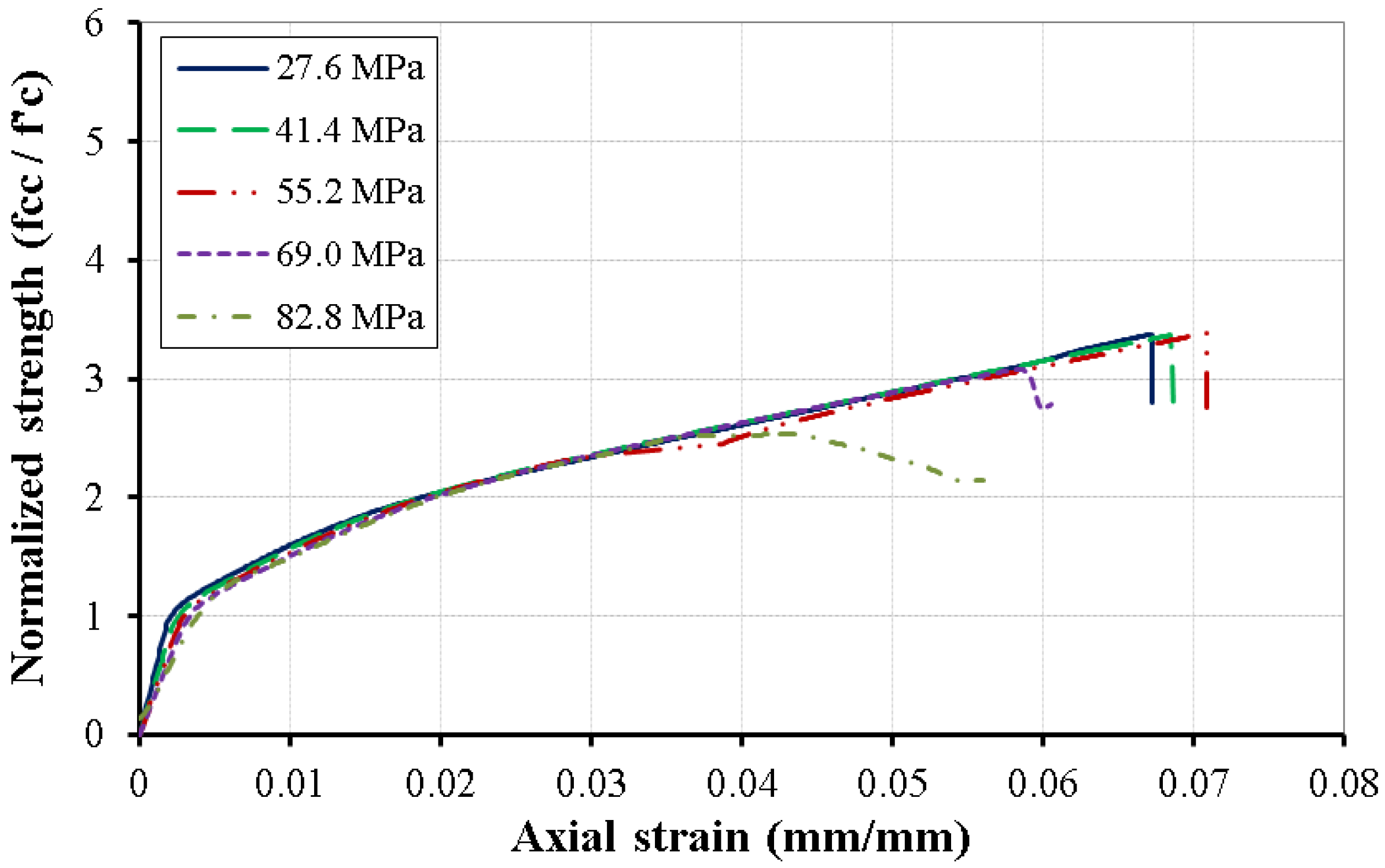
3.2. Unconfined Concrete Compressive Strength ()

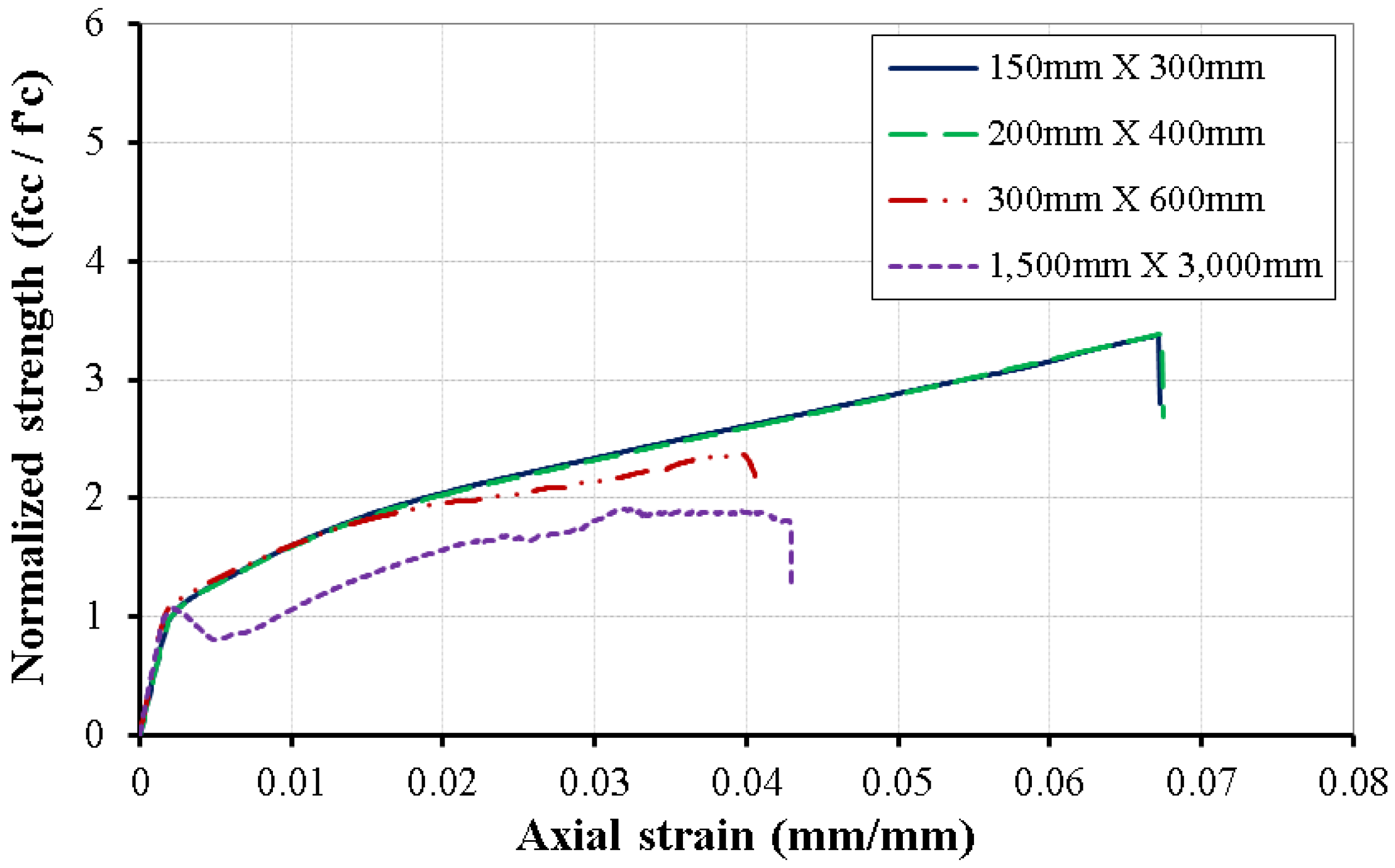
3.3. Column Size


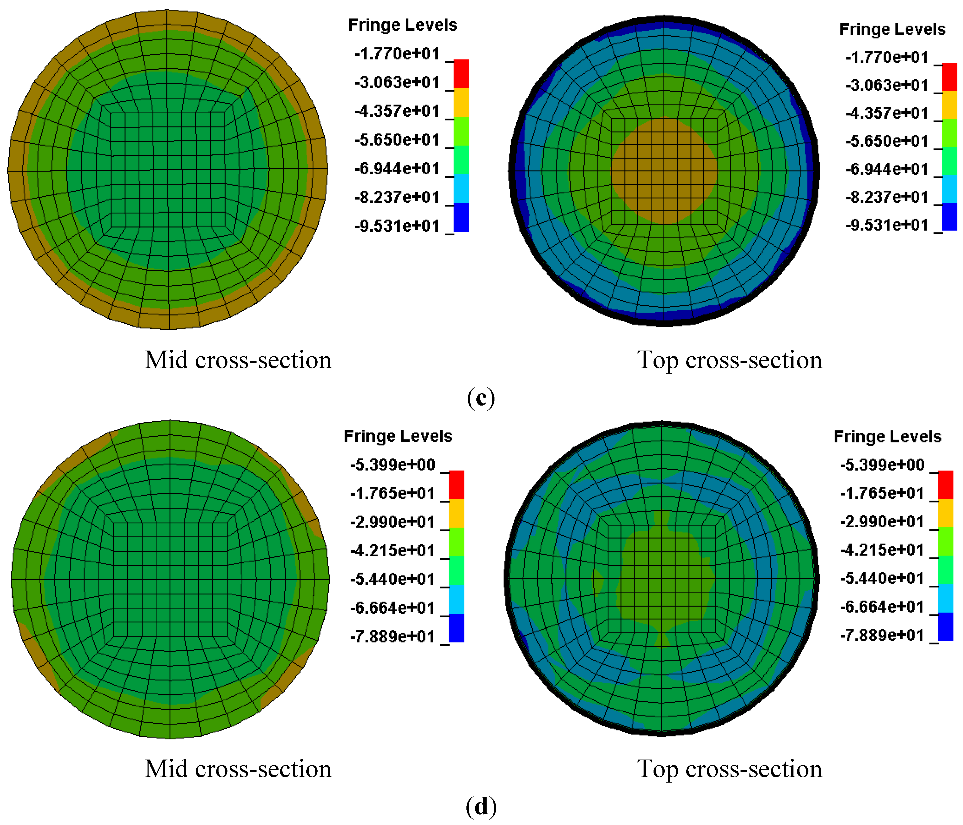
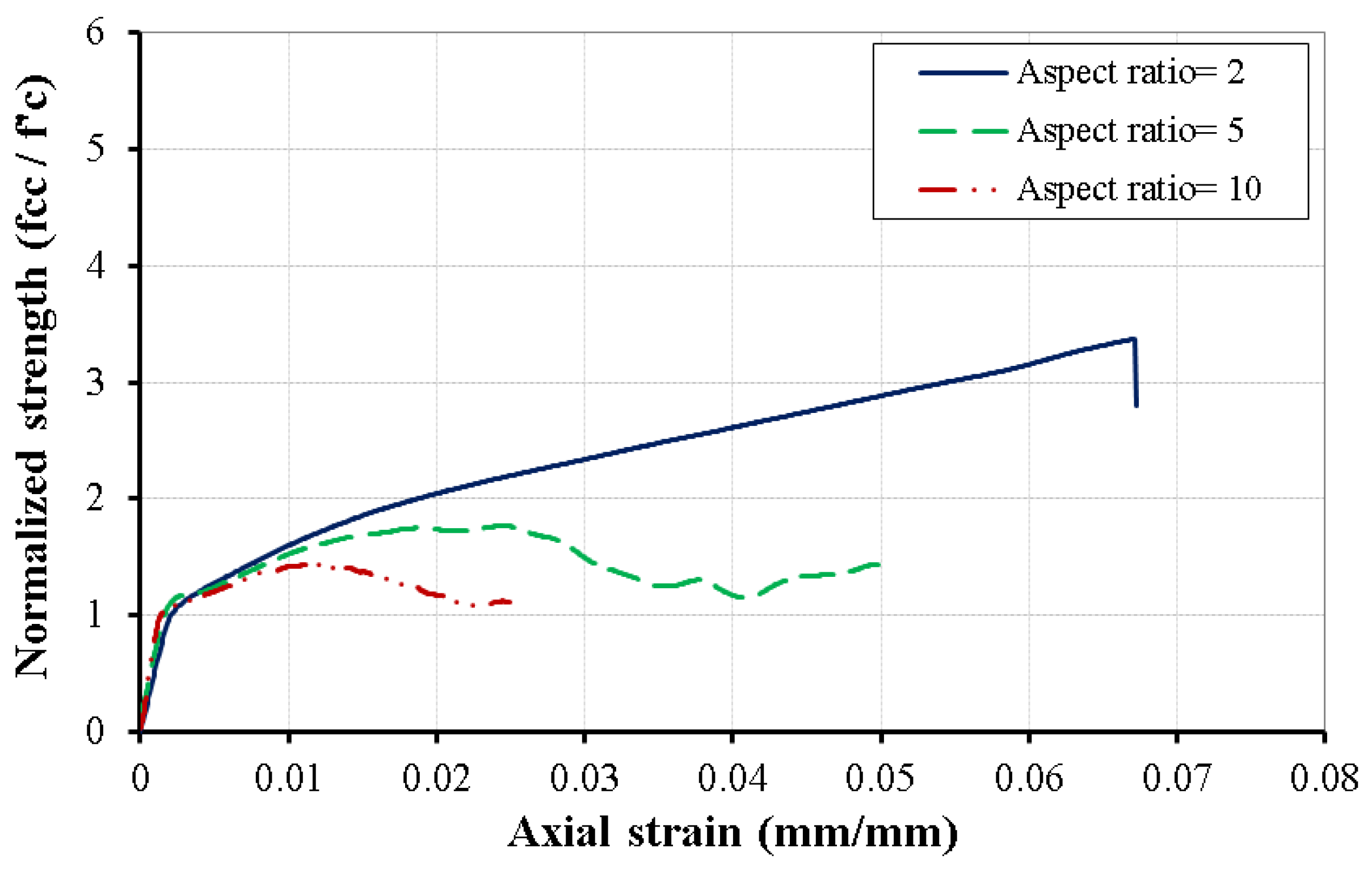
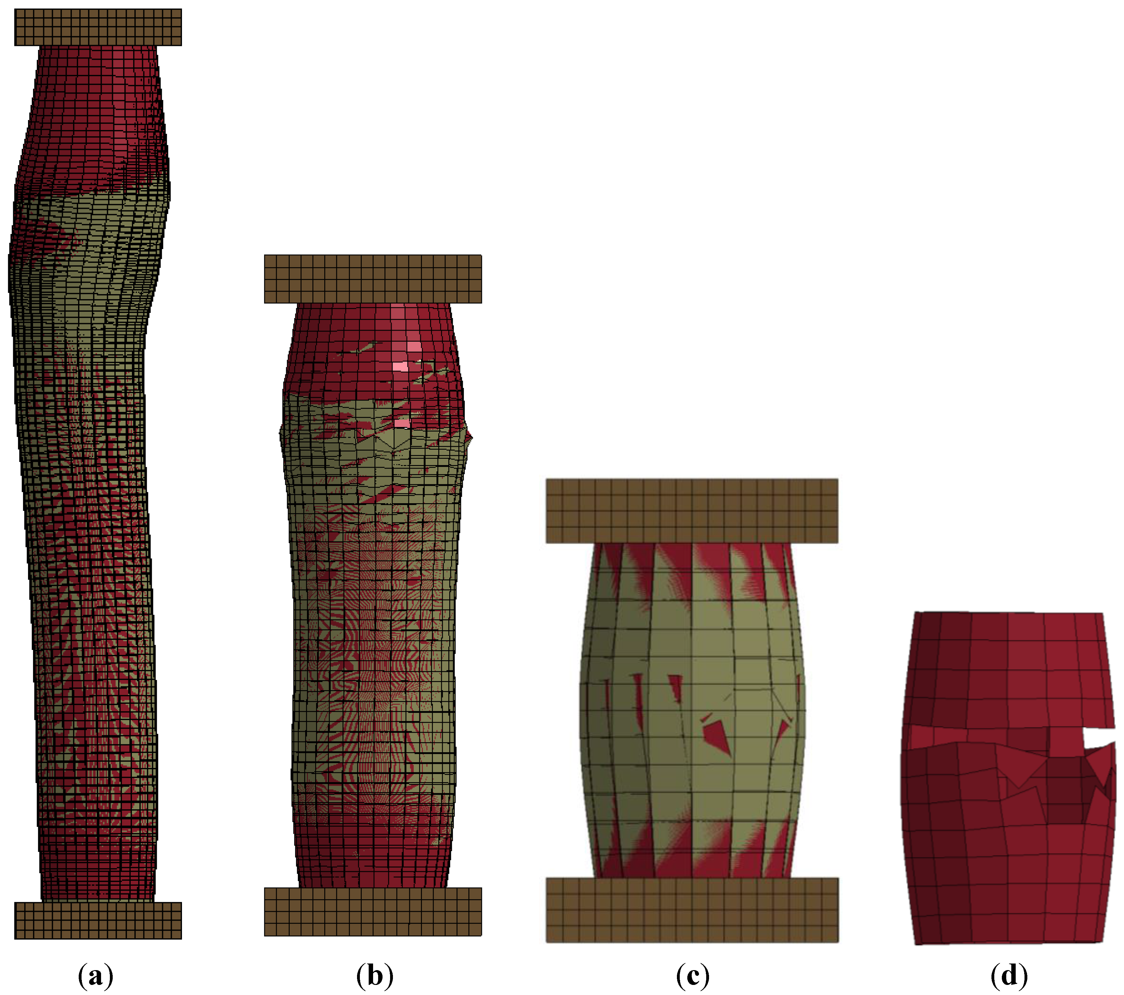
3.4. Column Aspect Ratio


4. Findings and Conclusions
Acknowledgments
Author Contributions
Conflicts of Interest
References
- Lechat, C.; Bunsell, A.R.; Davies, P. Tensile and creep behaviour of polyethylene terephthalate and polyethylene naphthalate fibres. J. Mater. Sci. 2011, 46, 528–533. [Google Scholar] [CrossRef]
- Venkatachalam, S.; Nayak, S.G.; Labde, J.V.; Gharal, P.R.; Rao, K.; Kelkar, A.K. Degradation and Recyclability of Poly (Ethylene Terephthalate); Available online: http://www.intechopen.com/books/polyester/degradation-and-recyclability-of-poly-ethylene-terephthalate- (accessed on 1 August 2015).
- Qasrawi, Y.; Heffernan, P.J.; Fam, A. Performance of concrete-filled FRP tubes under field close-in blast loading. J. Compos. Constr. 2015, 19. [Google Scholar] [CrossRef]
- Moon, J.; Lehman, D.E.; Roeder, C.W.; Lee, H.-E. Strength of circular concrete-filled tubes with and without internal reinforcement under combined loading. J. Struct. Eng. 2012, 139. [Google Scholar] [CrossRef]
- ElGawady, M.A.; Sha’lan, A. Seismic behavior of self-centering precast segmental bridge bents. J. Bridge Eng. 2010, 16, 328–339. [Google Scholar] [CrossRef]
- Sadeghian, P.; Fam, A. Bond-slip analytical formulation toward optimal embedment of concrete-filled circular FRP tubes into concrete footings. J. Eng. Mech. 2010, 136, 524–533. [Google Scholar] [CrossRef]
- ElGawady, M.; Booker, A.J.; Dawood, H.M. Seismic behavior of posttensioned concrete-filled fiber tubes. J. Compos. Constr. 2010, 14, 616–628. [Google Scholar] [CrossRef]
- Shao, Y.; Mirmiran, A. Experimental investigation of cyclic behavior of concrete-filled fiber reinforced polymer tubes. J. Compos. Constr. 2005, 9, 263–273. [Google Scholar] [CrossRef]
- Fam, A.; Flisak, B.; Rizkalla, S. Experimental and analytical modeling of concrete-filled FRP tubes subjected to combined bending and axial loads. ACI Struct. J. 2003, 100, 499–509. [Google Scholar]
- Zhang, W.; Shahrooz, B.M. Analytical and Experimental Studies into Behavior of Concrete-Filled Tubular Columns; Cincinnati Infrastructure Institute, University of Cincinnati: Cincinnati, OH, USA, 1997. [Google Scholar]
- Ispir, M. Monotonic and cyclic compression tests on concrete confined with pet-FRP. J. Compos. Constr. 2015, 19. [Google Scholar] [CrossRef]
- Bai, Y.-L.; Dai, J.-G.; Teng, J. Cyclic compressive behavior of concrete confined with large rupture strain FRP composites. J. Compos. Constr. 2014, 18. [Google Scholar] [CrossRef]
- Dai, J.-G.; Bai, Y.-L.; Teng, J. Behavior and modeling of concrete confined with FRP composites of large deformability. J. Compos. Constr. 2011, 15, 963–973. [Google Scholar] [CrossRef]
- Anggawidjaja, D.; Ueda, T.; Dai, J.; Nakai, H. Deformation capacity of rc piers wrapped by new fiber-reinforced polymer with large fracture strain. Cem. Concr. Compos. 2006, 28, 914–927. [Google Scholar] [CrossRef]
- Jirawattanasomkul, T.; Dai, J.-G.; Zhang, D.; Senda, M.; Ueda, T. Experimental study on shear behavior of reinforced-concrete members fully wrapped with large rupture-strain FRP composites. J. Compos. Constr. 2013, 18. [Google Scholar] [CrossRef]
- Mirmiran, A.; Zagers, K.; Yuan, W. Nonlinear finite element modeling of concrete confined by fiber composites. Finite Elem. Anal. Des. 2000, 35, 79–96. [Google Scholar] [CrossRef]
- Yu, T.; Teng, J.; Wong, Y.; Dong, S. Finite element modeling of confined concrete-i: Drucker-prager type plasticity model. Eng. Struct. 2010, 32, 665–679. [Google Scholar] [CrossRef]
- Rousakis, T.C.; Karabinis, A.I.; Kiousis, P.D.; Tepfers, R. Analytical modelling of plastic behaviour of uniformly FRP confined concrete members. Compos. Part B Eng. 2008, 39, 1104–1113. [Google Scholar] [CrossRef]
- Karabinis, A.I.; Rousakis, T.C.; Manolitsi, G.E. 3D finite-element analysis of substandard RC columns strengthened by fiber-reinforced polymer sheets. J. Compos. Constr. 2008, 12, 531–540. [Google Scholar] [CrossRef]
- Youssf, O.; ElGawady, M.A.; Mills, J.E.; Ma, X. Finite element modelling and dilation of FRP-confined concrete columns. Eng. Struct. 2014, 79, 70–85. [Google Scholar] [CrossRef]
- Jankowiak, T.; Lodygowski, T. Identification of parameters of concrete damage plasticity constitutive model. Found. Civ. Environ. Eng. 2005, 6, 53–69. [Google Scholar]
- Kmiecik, P.; Kamiński, M. Modelling of reinforced concrete structures and composite structures with concrete strength degradation taken into consideration. Arch. Civ. Mech. Eng. 2011, 11, 623–636. [Google Scholar] [CrossRef]
- Rezazadeh, M.; Costa, I.; Barros, J. Influence of prestress level on NSM CFRP laminates for the flexural strengthening of rc beams. Compos. Struct. 2014, 116, 489–500. [Google Scholar] [CrossRef] [Green Version]
- Hallquist, J.O. LS-DYNA Theory Manual; Livermore Software Technology Corporation: Livermore, CA, USA, 2006; Volume 3. [Google Scholar]
- Abdelkarim, O.I.; ElGawady, M.A. Analytical and finite-element modeling of FRP-concrete-steel double-skin tubular columns. J. Bridge Eng. 2015, 20. [Google Scholar] [CrossRef]
- Malvar, L.J.; Crawford, J.E.; Wesevich, J.W.; Simons, D. A plasticity concrete material model for DYNA3D. Int. J. Impact Eng. 1997, 19, 847–873. [Google Scholar] [CrossRef]
© 2015 by the authors; licensee MDPI, Basel, Switzerland. This article is an open access article distributed under the terms and conditions of the Creative Commons Attribution license (http://creativecommons.org/licenses/by/4.0/).
Share and Cite
Abdelkarim, O.I.; ElGawady, M.A. Concrete-Filled-Large Deformable FRP Tubular Columns under Axial Compressive Loading. Fibers 2015, 3, 432-449. https://doi.org/10.3390/fib3040432
Abdelkarim OI, ElGawady MA. Concrete-Filled-Large Deformable FRP Tubular Columns under Axial Compressive Loading. Fibers. 2015; 3(4):432-449. https://doi.org/10.3390/fib3040432
Chicago/Turabian StyleAbdelkarim, Omar I., and Mohamed A. ElGawady. 2015. "Concrete-Filled-Large Deformable FRP Tubular Columns under Axial Compressive Loading" Fibers 3, no. 4: 432-449. https://doi.org/10.3390/fib3040432
APA StyleAbdelkarim, O. I., & ElGawady, M. A. (2015). Concrete-Filled-Large Deformable FRP Tubular Columns under Axial Compressive Loading. Fibers, 3(4), 432-449. https://doi.org/10.3390/fib3040432