1. Introduction
Fir is a common softwood and a traditional construction material that has been extensively used in civil engineering for centuries. Construction using softwood is also an important part of infrastructure in many areas of the world: it can possibly be considered as one of the oldest construction materials, and its widespread use, from antiquity to the present, is essentially due to its high tensile strength, low weight density, large diffusion on the Earth, and good workability. However, softwood may be heavily affected by defects: natural defects (knots, shakes, cross grain), and defects caused during the treatment of felled timber may greatly reduce softwood’s mechanical properties and, particularly, its tensile strength.
Cracks in softwood are produced by the seasoning and changing of moisture content, and are an important natural defect that mostly reduces the capacity of wood beams: as an orthotropic material, wood presents different shrinkage coefficients in the tangential and radial directions, and the compatibility of the deformation leads to the formation of cracks. For these reasons, it is very difficult to prevent the opening of cracks, and only a controlled, careful, and slow seasoning may contribute to reducing their formation.
The introduction of laminated softwood (glulam) has minimized this problem for new timber construction. Dimensional changes in the length, depth, and width, and crack formation of structural, glued laminated wood due to changes in moisture content have been greatly reduced.
On the other hand, there is difficulty in achieving a reliable solution to this problem for existing timber constructions, or when solid-sawn timber is used for new constructions. A controlled seasoning may minimize the formation of cracks in softwood before the use of the beams, but a sudden variation in temperature or air humidity can provoke the opening of cracks, decades after the use of the beams.
The structural reinforcement and repair of timber structures is often necessary for historic timber elements in order to comply with new standards. Existing timber beams have been commonly subjected, either to reinforcement or replacement with standard methods, involving the use of traditional construction materials, such as metals (aluminum, steel,
etc.), or modern techniques with composite materials. The need for repair and improvement is typically very high for infrastructure: over 47% of the timber bridges in US are classified as structurally deficient in the National Bridge Inventory, based on visual inspection and the classification of defects [
1].
In order to restore the continuity of cracked timber beams, several solutions have been proposed: the use of self-tapping screws as reinforcement, perpendicular to the grain, has been studied by Blass and Bejtka [
2]. Parisi
et al. [
3] analyzed the use of small screws (7–8 cm) to prevent splitting near the joints of timber trusses. Tampone [
4] studied the use of metal brackets, and several others [
5,
6,
7] studied the application of metal braces. However, an important limitation is that metal elements are prone to oxidation and collapse in fires, as metals heat more readily than the timber.
Leijten [
8] has found that local steel reinforcements (screws, bolts,
etc.) inserted into timber members may lead to unexpected and unpredictable splitting, caused by the presence of hole clearance and by the stress concentration induced by the small diameter of the screws.
The use of composite materials for the reinforcement of existing timber members is not new [
9,
10,
11,
12,
13,
14,
15,
16]. Fiber-Reinforced Polymer (FRP) materials have been proven to have good tensile mechanical properties. Composite materials, especially glass and carbon reinforced polymer composites (GFRP and CFRP), are being progressively applied more in structural functions, not only for infrastructure or reinforcement of “modern” timber beams, but also for elements of architectural heritage. Usually, FRPs are applied where at least two of their valuable properties, e.g., high corrosion resistance and high tensile strength, may be exploited at the same time. In these situations, the total costs (material, application, and maintenance) of using composite materials are commensurate with traditional competitor materials, such as aluminum and steel, or with replacement. FRPs are usually applied using epoxy adhesives, inserted into pre-drilled holes, both in repair and in new-build applications. The bonded-in rod technology has been studied by Broughton and Hutchinson [
17], and the conclusion that epoxy adhesives resulted in a satisfactory performance compared to acrylic, polyurethane, and phenol-resorcinol adhesives, with a pull-out strength increasing linearly with bondline thickness. Even if there have been considerable advancements in relation to the performance of polyurethane adhesives, the bond strengths and overall mechanical properties of epoxy adhesives are still superior.
However, the varied range of composite products and the scattered mechanical characteristics of FRP elements presently available can cause significant difficulties for the engineer who approaches this problem. For this reason, choice of the strengthening layout and material should be guided by a precise analysis of the characteristics of the timber element to be repaired or reinforced in order to avoid unsuccessful interventions. The long-term durability of some FRP products needs to be studied and demonstrated [
18,
19].
The General Assembly of the United Nations proclaimed 2009 the International Year of Natural Fibers, but only very recently have researchers started to study the use of natural-based FRPs for applications in civil engineering. The aim of all major international organizations is to promote the efficiency and sustainability of natural fiber industries, and to encourage suitable policies from governments. However, there have been few studies to date on the use of natural fibers for the reinforcement of timber structures. Borri
et al. studied the use of bamboo, flax, and basalt strips to enhance to capacity of timber beams [
20]. De la Rosa
et al. also analyzed the effect of basalt strip reinforcements applied to the tension side of timber beams [
21]. Recently, Raftery
et al. used bonded-in basalt FRP rods to strengthen and repair low-grade, glued, laminated timber beams [
22].
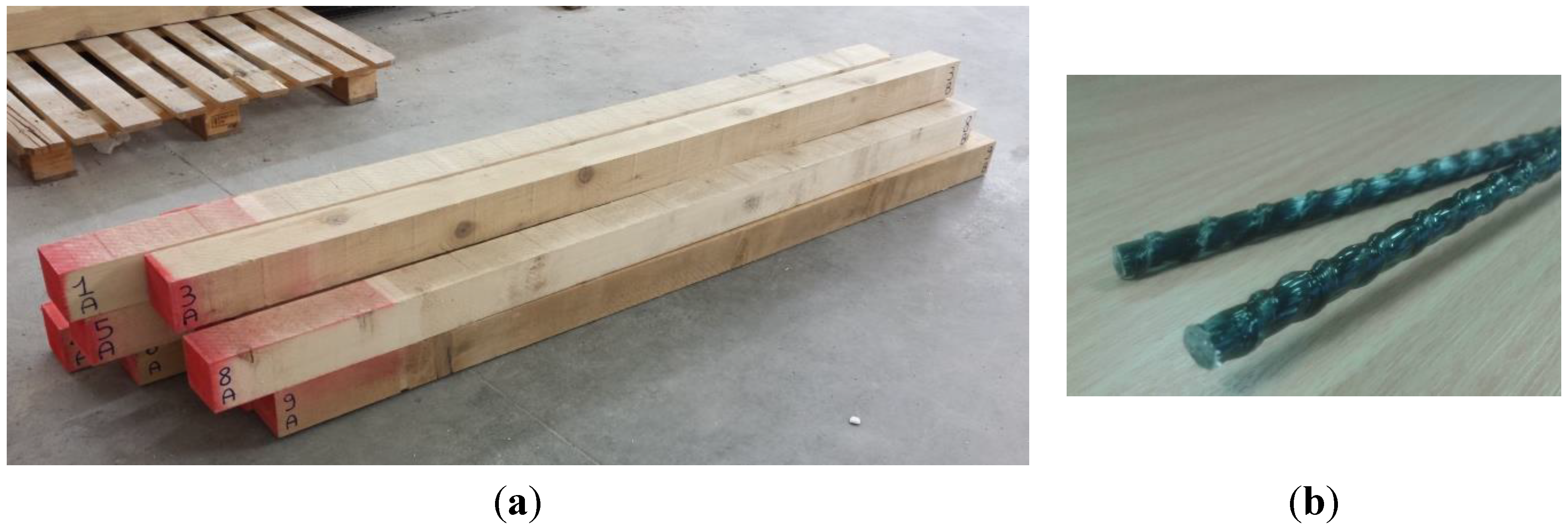
This paper describes an experimental study of the use of basalt FRP (BFRP) spikes in timber beams to restore the continuity of cracked and damaged sections. The repair technique consists in the application of 95-mm-long BFRP spikes, inserted into diagonal holes, perforated in the timber beams at a center-to-center distance of 200 mm. An artificially simulated cracking was produced by cutting the wood beams in half or notching them. A four-point-bending test was carried out on repaired and control timber beams, and results, in terms of bending capacity and modulus of elasticity, were compared to evaluate the effectiveness of the proposed repair technique. In comparison with the use of self-tapping screws, this procedure may be of interest because of the lower Young’s modulus of the BFRP spikes (similar to the one of timber), and for lower stress concentrations based on the larger dimensions of BFRP spikes.
2. Design of the Repair Technique
An efficient solution is achieved when an effective joint is used to connect the two timber parts. An effective joint should be characterized by enough strength to transmit the shear loads developed at the interface and stiff enough to restrict the slip between the two elements. Two extreme situations are shown in
Figure 1a: no connection (materials acting completely independent) and a perfect connection between the materials (full composite action). In the first case, slip occurs between the two timber elements resulting in two materials reacting independently to the bending loads and consequently to compressive and tensile stresses. In the second case, both elements are forced to act as a single element. The mechanical behavior of the joint has a significant importance for the behavior of the structure and it has a direct impact on the stress pattern as well as in its deformation mode.
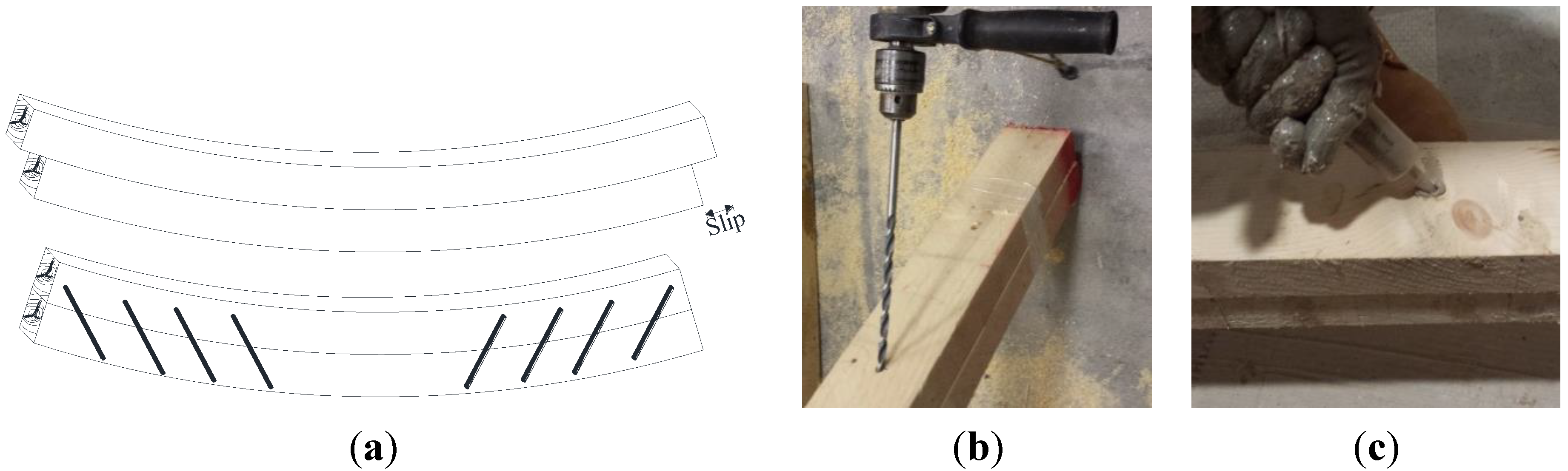
Figure 1.
(a) Schematic arrangement of Basalt Fiber Reinforced Polymer (BFRP) spikes; (b) Diagonal hole drilling; (c) Injection of epoxy putty.
Figure 1.
(a) Schematic arrangement of Basalt Fiber Reinforced Polymer (BFRP) spikes; (b) Diagonal hole drilling; (c) Injection of epoxy putty.
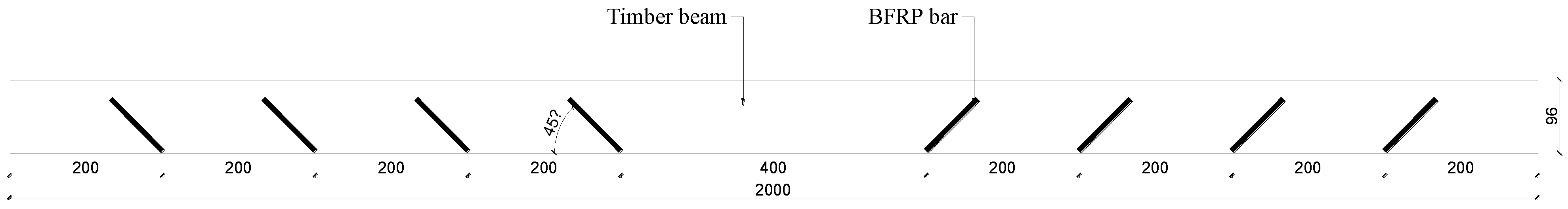
In this investigation, eight BFRP spikes were inserted into diagonal holes (45°) drilled in the timber beams (
Figure 1b) at a center-to-center distance of 200 mm. The use of inclined spikes was chosen because several experimental and numerical studies have shown how the increase of screw inclination affords an increase of the resistance and stiffness of the joints [
23,
24]. No spikes were applied to the central part of the softwood beams where shearing force is equal to zero. Bi-component epoxy putty was injected inside the holes before inserting the BFRP spikes to facilitate the connection between timber and reinforcement (
Figure 1c and
Figure 2). By considering that the spike and hole diameters were 6 and 8 mm, the epoxy bond thickness was approximately 1 mm.
Figure 2.
Layout of BFRP spikes (dimensions in (mm)).
Figure 2.
Layout of BFRP spikes (dimensions in (mm)).
In order to calculate the diameter (
d) of the spikes (
Table 1), the Johansen yielding theory [
25] was used and adapted. The Johansen approach identifies three different failure modes for a timber to timber joint: in the first mode (mode A), the final load-bearing capacity is obtained when the wood yields along the reinforcement (
Figure 3); the second (mode B) is characterized by a combination of the embedment failure in the timber and a single yield failure in the connector. The last failure mode (mode C) occurs when there is a combination of the embedment failure in the timber and a double yield failure in the connector.
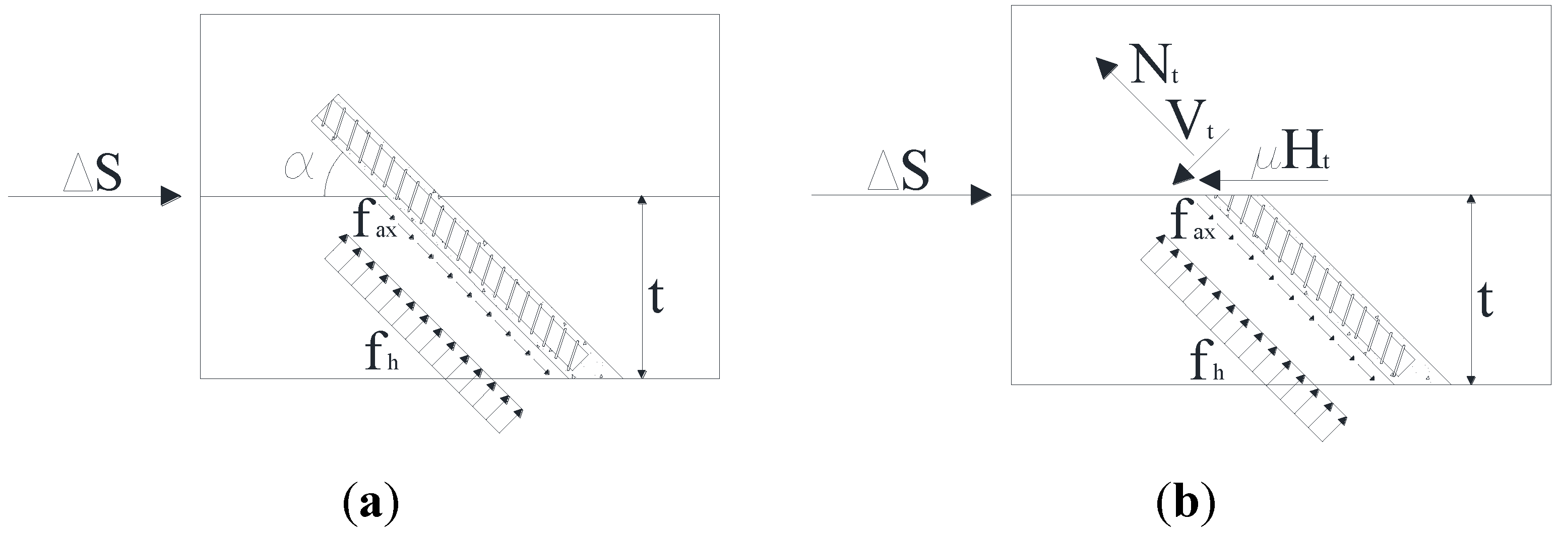
Figure 3.
Failure mode A: (a) stresses in the joint; (b) load on the interface between the timber elements.
Figure 3.
Failure mode A: (a) stresses in the joint; (b) load on the interface between the timber elements.
Table 1.
Mechanical properties of the BFRP spikes.
Table 1.
Mechanical properties of the BFRP spikes.
| Nominal Diameter (mm) | Weight Density (kg/m) | Failure Load (kN) | Tensile Strength (MPa) | Young’s Modulus (GPa) | Strain at Failure (%) |
|---|
| 6 | 0.452 | 21.5 | 761 | 36.56 | 2.08 |
Due to the linear elastic response of BFRP spike, only the failure mode A was considered here. The ultimate load-bearing capacity can be evaluated from internal forces in the non-deformed state:
where
Nt and
Vt are the axial and shearing forces applied on the spike, respectively;
Ht is the horizontal force at the interface between the two timber elements, μ is the coefficient of friction, α is the angle of inclination of the spike with respect to the grain direction (equal to 45°) and Δ
S is the slip load at the interface between the two timber parts. Assuming a perfect connection between the two parts the slip load Δ
S for a length Δ
z (equal to 200 mm) can be evaluated as:
where
VEd is the average shearing force,
Sx is the first moment and
Ix is the second moment of the beam cross section, respectively, calculated as:
where
b is the width and
h is the height of the cross section.
The horizontal force is defined as:
The axial load
Nt acting on a BFRP spike can be calculated:
where
d is the nominal diameter of the composite element,
t is the embedded length and
fax is the withdrawal strength of the timber, defined according to the Eurocode 5 [
26] as:
The lateral force acting on the BFRP spike can be evaluated:
where
fh is the embedment strength for timber according with Eurocode 5 for timber with pre-drilled holes, based on a large number of embedding tests, and equal to:
Substituting Equations (5) and (7) into the Equations (1) and (4), the following equation is obtained:
Assuming a coefficient of friction for the timber equal to 0.3, the required spike’s diameter is equal to 5.34 mm and according to the suitable commercial diameters, it was decided to use a 6-mm-diameter spike.
4. Test Setup and Test Results
Five series of bending tests were performed on undamaged, damaged and repaired softwood beams (
Table 3). Twenty-four beams were subjected to the four-point-bending test, according to UNI EN 408 standard [
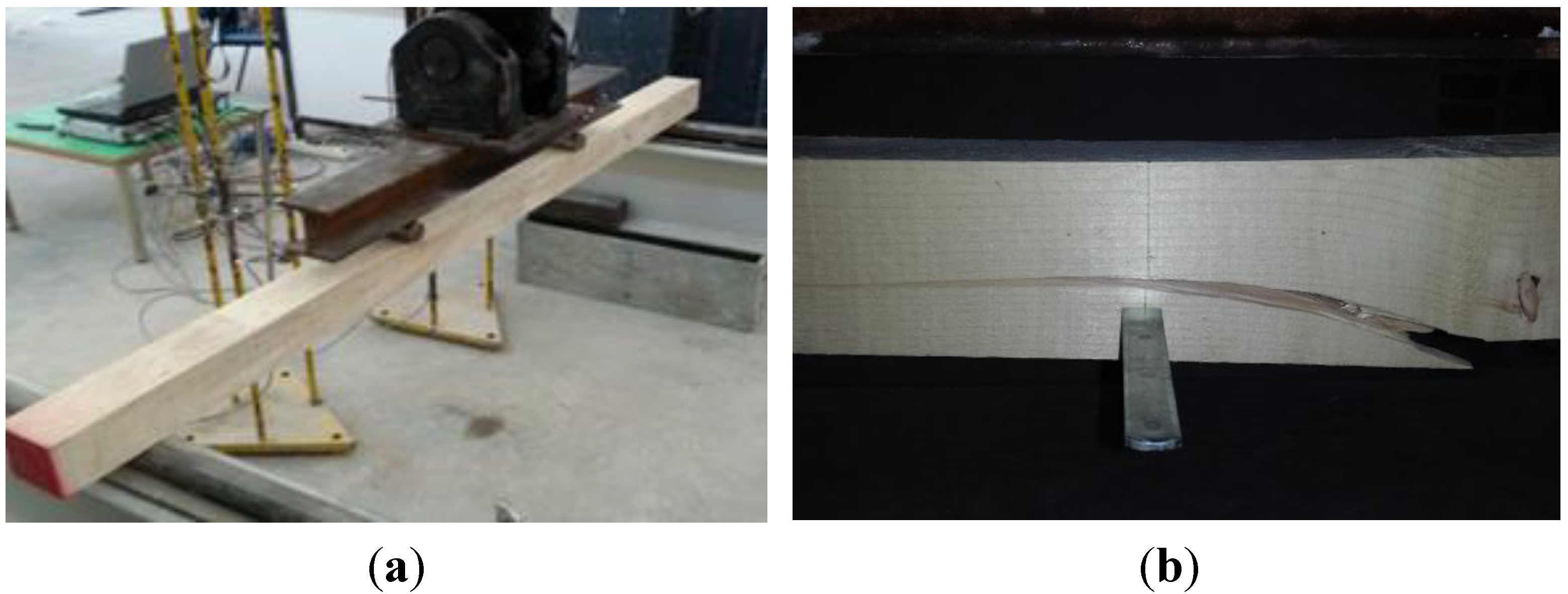
31]. The strength tests were carried out at a span length of 1728 mm and a distance between the loading heads of 576 mm. In order to decrease the local crushing of the wood, the load was applied through two 42-mm-diameter solid steel cylinders. Displacement controlled loading ensued with a crosshead speed of 2 mm/min.
Load was applied monotonically until failure by means of a hydraulic cylinder connected by a circuit to a hand pump. The vertical displacement of the beams was recorded using three inductive transducers (LVDT). The bending strength
fm was calculated according to:
where
Fu is the maximum load;
a is the distance between the point of application of the load and the nearest support;
W is the modulus of resistance of the section. From these measured values and taking into account the cross-sectional dimensions of the timber beams, a global modulus of elasticity
Em,g can be calculated with the following formulation:
where
l is the distance between the rollers;
F2 −
F1 is an increment of load on the straight-line portion of the load deformation curve;
w2 −
w1 is the increment of deformation corresponding to
F2 −
F1;
b is width of cross section. In order to have a overall information of the stiffness properties of the timber beams it was decided to measure and calculate only the global modulus of elasticity evaluated according to Equation (11). The test setup is shown in detail in
Figure 5a.
Table 3.
Test matrix.
| Index | Number of Beams | Timber Beam | Repair |
|---|
| UNS_series | 10 | - | - |
| US_series | 3 | Cut in half | - |
| UN_series | 3 | Notched | - |
| RS_series | 5 | Cut in half | BFRP spike |
| RN_series | 3 | Notched | BFRP spike |
Figure 5.
(a) Four-point-bending test setup; (b) Typical tensile failure mode of control beams near a knot or due to grain deviation.
Figure 5.
(a) Four-point-bending test setup; (b) Typical tensile failure mode of control beams near a knot or due to grain deviation.
4.1. Control Beams
Fourteen control beams were subjected to flexure in four-point-bending. These results have been reported only for the purpose of quantitatively calculating the effectiveness of the repair intervention through a comparison with the results of identical tests performed on the strengthened beams. Various modes of fracture were detected in the timber beams, but all on the tension side: simple tension, cross grain tension, knot influenced (
Figure 5b). Knots and grain deviation highly influenced the propagation of the cracks for all control specimens. Deflection characteristics of the tested control beams are shown in
Table 4, the average bending strength was 24.5 MPa (dev. 8.3 MPa) and the global modulus of elasticity was 5932 MPa (dev. 907 MPa).
Table 4.
Test results (control beams).
Table 4.
Test results (control beams).
| Timber Beam Condition | Index | Maximum Load (kN) | Bending Strength (MPa) | Global Modulus of Elasticity (MPa) | Deflection at Max Load (mm) |
|---|
| Undamaged Beams | UNS_1 | 13.0 | 26.2 | 6077 | 37.0 |
| UNS_2 | 7.5 | 15.2 | 5148 | 23.5 |
| UNS_3 | 14.8 | 29.9 | 6825 | 36.5 |
| UNS_4 | 8.6 | 17.2 | 6029 | 21.4 |
| UNS_5 | 15.7 | 31.6 | 5668 | 60.3 |
| UNS_6 | 12.7 | 25.5 | 4684 | 36.2 |
| UNS_7 | 16.8 | 33.8 | 7059 | 45.5 |
| UNS_8 | 15.5 | 31.2 | 7059 | 32.5 |
| UNS_9 | 12.9 | 26.0 | 6158 | 29.2 |
| UNS_10 | 4.1 | 8.18 | 4611 | 12.6 |
| Average | 12.1 | 24.5 | 5932 | 33.5 |
| (St. deviation) | (4.1) | (8.3) | (907) | (13.3) |
| Notched beams | UN_1 | 6.8 | 13.5 | 6137 | 16.3 |
| UN_2 | 9.8 | 19.9 | 5657 | 28.6 |
| UN_3 | 8.3 | 16.6 | 5073 | 21.0 |
| Average | 8.3 | 16.7 | 5622 | 22.0 |
| (St. Deviation) | (1.3) | (2.6) | (435) | (5.0) |
| Beams cut in half | US_1 | 6.5 | 12.8 | 1112 | 81.0 |
| US_2 | 6.1 | 11.9 | 1141 | 72.7 |
| US_3 | 6.5 | 13.0 | 1203 | 71.0 |
| Average | 6.4 | 12.5 | 1152 | 74.9 |
| (St. Deviation) | (0.18) | (0.47) | (38.0) | (4.39) |
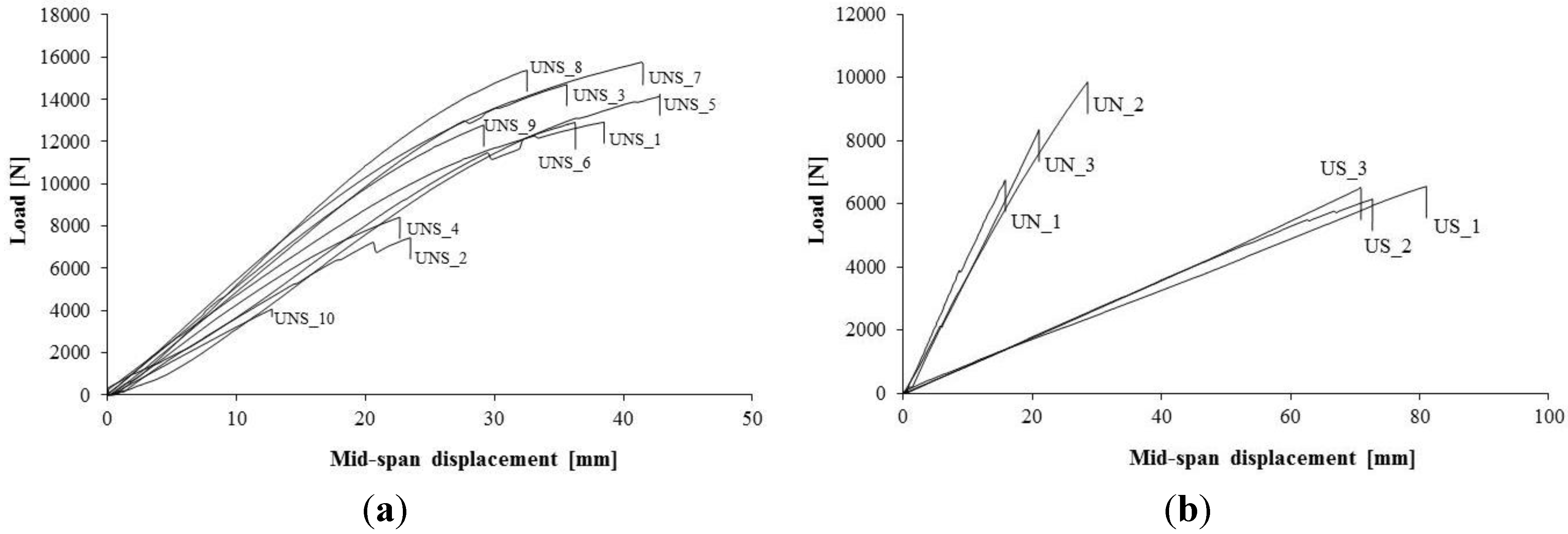
Load-displacement curves (
Figure 6a) are initially linear. As the load increases, timber begins to yield in the compression zone and failure occurs in the tension zone when the tensile strength is reached. Three beams (UNS_2; UNS_4 and UNS_10) exhibited an early failure influenced by the presence of a large defect (knot) in the tension side (
Figure 5b). The scatter in the capacity values of control beams, where the presence of grain deviation and knots influence the failure mode, is very high.
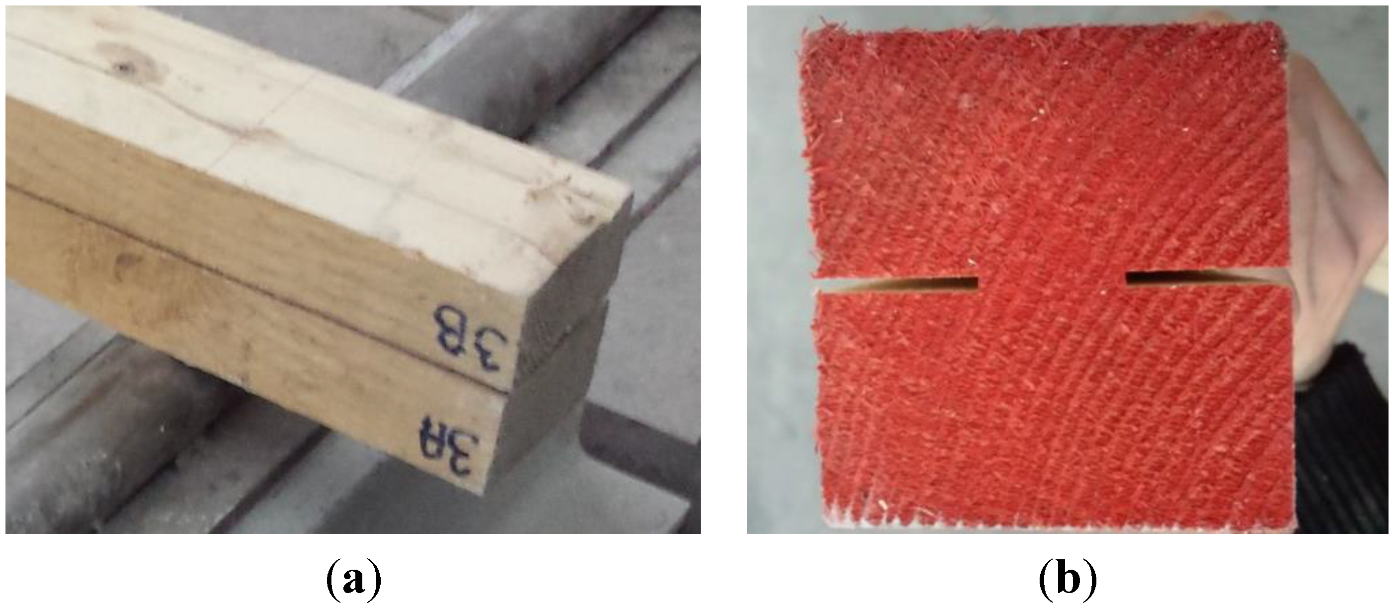
Six beams were subjected to four-point-bending after being artificially damaged: three timber beams were divided in-half and three were cut with two 35 mm horizontal notches (
Figure 7). The control notched specimens (UN_1, UN_2 and UN_3) exhibited an average bending strength of 16.7 MPa and a global modulus of elasticity of 5622 MPa. Furthermore the failure of these specimens occurred in the area where bending moment is maximum. Fracture was influenced by the presence of the two notches: beams UN_1 and UN_3 failed due to separation of upper part half from lower half and subsequent tensile failure in tension side. This caused a significant reduction in beam capacity shifting from 12.1 (undamaged beams) to 8.3 kN (notched beams):
The control specimens that were cut in half (US_1, US_2 and US_3) exhibited an average bending strength of 12.5 MPa and a global modulus of elasticity of 1152 MPa, with a reduction compared to undamaged beams of approximately 49% and 87%, respectively. Failure emerged in proximity of the application point of the load at the tension side. A significant slippage of the two parts of the beams was clearly recorded during the tests. All the artificially damaged (cut in half and notched timber beams) usually showed an elastic-linear response up until the failure (
Figure 6b).
Figure 6.
Load-Displacement curves: (a) control un-damaged beams; (b) beams that were cut in half or notched.
Figure 6.
Load-Displacement curves: (a) control un-damaged beams; (b) beams that were cut in half or notched.
Figure 7.
(a) Timber beams cut in half; (b) Notched beams.
Figure 7.
(a) Timber beams cut in half; (b) Notched beams.
4.2. Repaired Beams
BFRP spikes have been applied to cut-in-half (
Figure 7a) and to notched beams (
Figure 7b) with the aim to restore the continuity of damaged timber beams.
Three repaired notched beams were tested (RN_1, RN_2 and RN_3) and test results are reported in
Table 5. The application of the BFRP spikes produced an increase of the average bending strength of 56.1% and of the global modulus of elasticity of 19% compared to the control notched beams (
Table 6). Both for control and repaired beams, an elastic response has been recorded. The main result is that timber beams did not fail due to separation of the upper from the beam’s lower part near the notches, but beams exhibited tensile timber failures initiated by defects (mainly grain deviation and knots). The deviation in the strength value of beams, also considering the limited number of tests performed, is also relatively low. Furthermore, it can broadly be said that the repaired notched beams allow the achievement of the bending capacity and stiffness of the control and undamaged beams.
Table 5.
Test results (repaired beams).
Table 5.
Test results (repaired beams).
| Index | Maximum Load (kN) | Bending Strength (MPa) | Global Modulus of Elasticity (MPa) | Deflection at Maximum Load (mm) |
|---|
| RS_1 | 9.91 | 19.4 | 5855 | 73.8 |
| RS_2 | 5.11 | 9.97 | 6250 | 29.2 |
| RS_3 | 5.29 | 10.5 | 3136 | 48.4 |
| RS_4 | 9.68 | 18.7 | 5377 | 71.0 |
| RS_5 | 8.28 | 16.5 | 3900 | 54.2 |
| Average | 7.65 | 15.0 | 4904 | 55.3 |
| (St. Deviation) | 2.08 | 4.02 | 1189 | 16.2 |
| RN_1 | 12.4 | 29.8 | 7524 | 29.8 |
| RN_2 | 13.6 | 27.2 | 6233 | 28.8 |
| RN_3 | 10.5 | 21.0 | 6327 | 51.0 |
| Average | 12.2 | 26.0 | 6695 | 36.5 |
| (St. Deviation) | 1.29 | 3.73 | 588 | 10.3 |
Table 6.
Results of control and repaired beams.
Table 6.
Results of control and repaired beams.
| Index | Repaired | Condition | Maximum Load (kN) | Bending Strength (MPa) | Deflection at Maximum Load (mm) |
|---|
| UNS_series | No | - | 12.1 | 24.5 | 33.5 |
| US_series | No | Notched | 6.40 | 12.5 | 71.0 |
| UN_series | No | Cut-in-half | 8.32 | 16.7 | 22.0 |
| RN_series | Yes | Notched | 12.2 | 26.0 | 36.5 |
| RS_series | Yes | Cut-in-half | 7.65 | 15.0 | 55.3 |
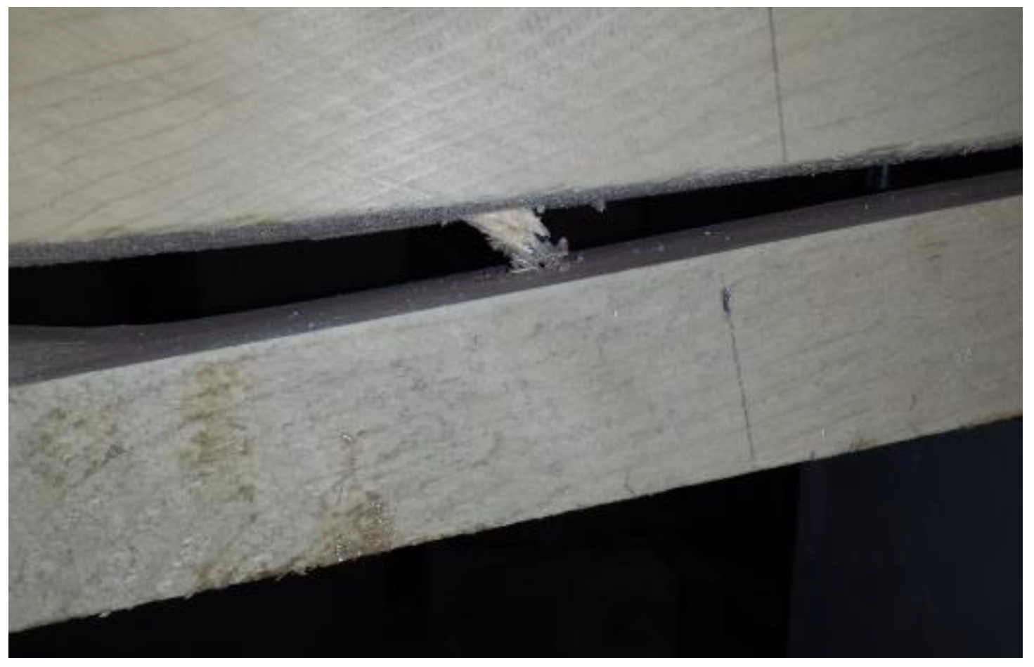
The repaired cut-in-half beams (RS_1, RS_2, RS_3, RS_4 and RS_5) exhibited an average bending strength of 15.0 MPa and a global modulus of elasticity of 4904 MPa. Failure, again knot influenced, occurred in the timber material on the tension side where the bending moment is maximal. After timber failure, the BFRP spikes did not exhibit any damage, but partially separated from the epoxy resin in the holes. Slippage was also generated by timber shear failure near the holes caused by the low shear strength of fir wood (
Figure 8).
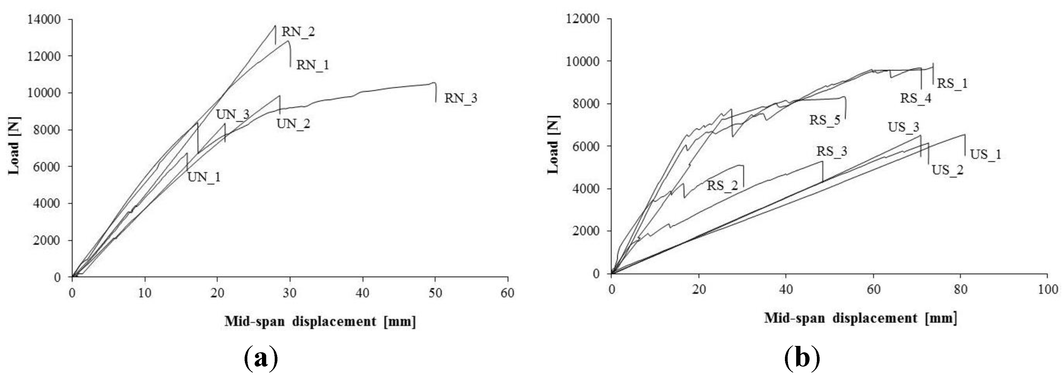
Figure 9 shows the load-deflection response of control and repaired beams that were cut in half. The load-displacement graphs generally show that there is a large amount of vertical mid-span deflection even for low loads due to the slippage of the BFRP spikes.
After an initial elastic phase, repaired beams (RS_series) exhibited a plastic behavior. Increases of bending strength compared to control beams were limited due to low quality of timber material (fir wood) and separation of BFRP spikes from the epoxy resin. Beams RS_2 and RS_3 collapsed for a low bending load due the presence of a large knot defect in timber tension zone. The insertion of the BFRP spikes resulted in moderate enhancements in the beam ultimate capacity (+19.8%) while more significant improvements in the stiffness were obtained (+325.7%) and it is essentially due to the low values of stiffness of cut-in-half beams. However, the insertion of the BFRP spikes did not cause the achievement of the values of the control timber beams in terms of bending capacity and stiffness.
Another interesting feature of the load-deflection curves is that repaired specimens after an initial decrease of the load due to a beam cracking, were able to withstand a further increase in load. The BFRP repaired beams demonstrated an initial linear elastic behavior and exhibited brittle timber tensile-flexural failures on the lower half of the timber beam when subject to flexural loading. After this, a pseudo-ductile behaviour of the repaired beams has been recorded.
Figure 8.
Pull out of the BFRP spike.
Figure 8.
Pull out of the BFRP spike.
Figure 9.
Load-Displacement curves: (a) control (US-series) and repaired (RS-series) beams cut in half, notched beams; (b) control (UN-series) and repaired (RN-series) beams that were cut in half.
Figure 9.
Load-Displacement curves: (a) control (US-series) and repaired (RS-series) beams cut in half, notched beams; (b) control (UN-series) and repaired (RN-series) beams that were cut in half.
For both notched and cut-in-half beams, experimental testing in flexure has demonstrated that the insertion of BFRP spikes incorporating basalt fiber reinforcement epoxy-bonded onto softwood (low-grade) beams can increase the beam capacity and stiffness and introduce pseudo-ductile behavior into the hybrid beams in comparison with the linear elastic brittle tensile failure experienced by the control beams (
Figure 10). However, this non-linear behavior was mainly caused by slippage phenomena of the BFRP spikes demonstrating the limited effectiveness of these epoxy-bonded connections.
Figure 10.
Timber tensile-flexural failures (beams that were cut in half): (a) in the lower half; (b) both in the lower and upper half.
Figure 10.
Timber tensile-flexural failures (beams that were cut in half): (a) in the lower half; (b) both in the lower and upper half.


