
Theoretical and Experimental Investigations of Oxygen Activation Effect of Carbon Nanofibers Interacting with Polypyrrole


1
School of Chemistry and Chemical Engineering, Southeast University, Nanjing 211189, China
2
Suzhou Research Institute, Southeast University, Suzhou 215123, China
*
Author to whom correspondence should be addressed.
Fibers 2024, 12(1), 4; https://doi.org/10.3390/fib12010004
Submission received: 13 November 2023
/
Revised: 13 December 2023
/
Accepted: 18 December 2023
/
Published: 27 December 2023
(This article belongs to the Special Issue Nanofibers: Biomedical Applications)
Abstract
:Theoretical modeling calculations and experimental measurements were adopted to investigate the oxygen activation effect of carbon nanofibers (CNFs) interacting with polypyrrole (PPY). The CNF undergoes a hydrothermal oxidation process to form epoxy and hydroxyl groups containing carbon nanofibers (CNF-O). The oxygen activation effect of CNF on the electronic and electrochemical properties was investigated through the interfacial interaction between CNF-O and PPY. Theoretical modeling calculation discloses that CNF-O/PPY exhibits lower electronic bandgaps (0.64 eV), a higher density of states (10.039 states/eV), and a lower HOMO–LUMO molecular orbital energy gap (0.077 eV) than CNF/PPY (1.56 eV, 7.946 states/eV and 0.112 eV), presenting its superior electronic conductivity and electroactivity. The Mulliken population and charge density difference analysis disclose the stronger interface interaction of CNF-O/PPY caused by epoxy and hydroxyl groups. Cyclic voltammogram measurements reveal that CNF-O/PPY exhibits a higher response current and a higher specific capacitance (221.1–112.2 mF g−1) than CNF/PPY (57.6–24.2 mF g−1) at scan rates of 5–200 mV s−1. Electrochemical impendence spectrum measurements disclose that CNF-O/PPY exhibits a lower charge transfer resistance (0.097 Ω), a lower ohmic resistance (0.336 Ω), a lower Warburg impedance (317 Ω), and a higher double-layer capacitance (0.113 mF) than CNF/PPY (1.419 Ω, 9.668 Ω, 7865 Ω, and 0.015 mF). Both theoretical and experimental investigations prove that CNF-O/PPY presents an intensified intermolecular interaction rather than CNF/PPY. The promotive oxygen activation effect of CNF could contribute to improving the electronic and electrochemical properties of CNF-O/PPY.

1. Introduction
Versatile graphite carbon materials have been widely used as various electrodes, substrates, or supporting carriers for chemical, electrochemical, biological, and electronical applications due to their corrosion resistance, feasible surface activity, high conductivity, and surface area properties [1,2,3,4]. Redox-active materials, such as transition metal oxides/sulfides/nitrides, conductive polymers, polyoxometalates, and their composites, are usually applied as the stable and conductive electrode materials of chemosensors and biosensors in analytical testing areas, pseudo-supercapacitors, and batteries in electrochemical energy storage areas. Various carbon materials, such as graphite, graphene, carbon fiber, carbon nanotubes, and carbon dots, can be applied to electrical double-layer capacitors [5,6]. The formulation of redox-active and carbon-material composites has become a useful strategy for constructing highly electroactive energy storage electrode materials. In particular, carbon fibers have highly accessible surface areas, chemical/electrochemical stability, electrical conductivity, and mechanical flexibility, acting as reasonable electrodes or substrate materials for versatile supercapacitor electrode applications [7,8,9,10,11,12]. However, bare carbon fibers have smooth surfaces with physiochemical inertness, which causes low interfacial interaction with electrolyte ions and electroactive materials. Furthermore, the weak interaction of van der Waals forces between carbon fibers and electroactive materials usually causes low electronic and electrochemical performance [13]. Carbon fibers usually show very low electrical double-layer capacitance in reversible charge–discharge processes. Various activation methods, such as wet chemical, electrochemical, or microwave treatments, have been developed to activate carbon fibers [14]. Oxygen-containing functional groups were introduced on the graphite framework, which could improve the interfacial interaction, electroactivity, and capacitance performance as well [15,16]. So, a well-designed graphite carbon electrode with functional groups can be applied for high-performance sensor and supercapacitor applications [17]. Moreover, various conductive polymers are usually used to modify carbon fibers to prepare electroactive electrodes for electrochemical applications [11,18]. In particular, polypyrrole, one kind of typical conductive polymer, has good biocompatibility for the specified biosensor application and good electroactivity for a specified supercapacitor application [19,20,21]. PPY-based biosensors have been widely investigated and reported. Electrochemical testing systems are also widely adopted for the sensitive testing of various molecules according to the response current density. Well-designed carbon nanofiber/conductive polymers have become feasible electrode materials in terms of achieving these functions [22]. The surface oxygen functional groups play an important role in the electrochemical properties of carbon nanofibers [23,24]. However, interfacial interaction is not well investigated between the activated graphite carbon nanofibers and the conductive polymer of pyrrole, which has a significant effect on the electronic and electrochemical properties of the activated carbon nanofiber/conductive polypyrrole composite. In addition, the current response has been widely applied as a sensitive indicator of electrothermal quantitative determination of target molecules. So, it has become reasonable to construct a functional carbon nanofiber/polypyrrole composite electrode. Electrochemical capacitance measurements were used for electroactivity evaluation. The simulation calculation of molecular dynamics and density functional theory was used to explain the experimental results and disclose the correlation between the theoretical data and the experimental data [25].
In this study, graphite carbon nanofibers (CNFs) were adopted as active electrode substrate materials. Surface activation through hydrothermal oxidation treatment is applied to form oxygen functional groups-containing carbon nanofibers (CNF-O). The electroactive polymer polypyrrole (PPY) is used to modify CNF-O to form CNF-O/PPY composite electrode material. The oxygen-activation effect of CNF in CNF-O/PPY is investigated by studying the interfacial interaction between CNF-O and PPY. The CNF-O/PPY nanocomposite is applied as a Faradaic supercapacitor electrode material to investigate superior response current capacitance performance. The molecular modeling calculations and electrochemical experimental measurements were applied to investigate the electronic and electrochemical properties of the reactive CNF-O/PPY electrode material.
2. Materials and Methods
2.1. Materials
The pyrrole monomer (Py, CAS number 109-97-7, analytical grade purity, 99%) was purchased from Sinopharm chemical reagent Co., Ltd., Shanghai, China. Nitric acid (HNO3, CAS number 7697-37-2, P Analytical grade purity, weight concentration 69%) and sulfuric acid (H2SO4, CAS number 7664-93-9, analytical grade purity, weight concentration 98%) were purchased from Sinopharm chemical reagent Co., Ltd., Shanghai, China. The carbon fibers were purchased from Yangzhou carbon fiber Co., Ltd., Yangzhou, China. Other chemical reagents of analytical grade were purchased from Sinopharm chemical reagent Co., Ltd., Shanghai, China, and used without further purification. Deionized water and the above materials were used directly without further purification. All aqueous solutions were prepared using double-distilled water.
2.2. Synthesis, Characterization, and Experimental Measurements
The oxidation activation of CNF was conducted in the diluted HNO3 solution through the hydrothermal oxidation process using a polytetrafluoroethylene Teflon-lined stainless reactor. Thermal activation was then conducted in an argon atmosphere using a tubular furnace, forming the product of CNF-O. The interfacial interaction of polypyrrole (PPY) was conducted through electrochemical polymerization of pyrrole monomer on the surface of CNF-O, forming CNF-O/PPY.
The surface morphology and microstructure of CNF, CNF-O, and CNF-O/PPY were investigated by field-emission scanning electron microscopy (FESEM, Ultra-Plus Zeiss, Oberkochen, Germany). Element analysis was conducted by energy dispersive X-ray (EDX, Sirion FEI, Hillsboro, OR, USA) diffraction in order to identify the element composition of CNF and CNF-O. X-ray photoelectron spectroscopy (XPS, Thermo Scientific K-Alpha, Waltham, MA, USA) was used to analyze the surface oxygen-containing functional groups on CNF-O.
Electrochemical measurements were conducted in 1.0 M H2SO4 electrolyte solution using a three-electrode system. CNF-O/PPY, platinum sheet (Pt), and saturated calomel electrode (SCE) were used as the working electrode, counter electrode, and reference electrode, respectively. Electrochemical properties were measured using a CHI760C electrochemical workstation, including cyclic voltammetry (CV) and electrochemical impedance spectroscopy (EIS).
2.3. Theoretical Calculation
The density functional theory (DFT)-based molecular modeling calculation was performed to investigate the electronic properties and interfacial interaction of CNF-O/PPY through Materials Studio [26]. The DMol3 package was used to calculate the highest occupied molecular orbital–lowest unoccupied molecular orbital (HOMO–LUMO) energy gaps, and the CASTEP package was used to calculate the density of states (DOS), electronic energy gap, and charge density difference. In view of the exchange and correlation of the electronic interaction, the Predew, Burke, and Ernzernhof (PBE) generalized gradient approximation level was conducted in the DFT calculation. The cut-off energy of the plane wave functional was 350 eV. The thresholds of the convergence tolerance were set as follows. The convergence tolerance of energy was under 5 × 10⁻⁵ eV per atom, the maximal displacement was 0.005 Å, and the maximal stress was 0.2 GPa. The maximal force was 0.1 eV per Å.
3. Results and Discussion
3.1. Morphology and Microstructure
Figure 1A,B show the overall view and magnified view of FESEM images of carbon nanofibers of CNF and oxygen-activated carbon nanofibers of CNF-O. Two kinds of carbon nanofibers, CNF and CNF-O, are comprised of individual nanofibers that are highly aligned and packaged together to form carbon nanofiber bundles. Individual nanofibers have a diameter of 100–130 nm. Nanofiber bundles have a diameter of 7.4–8.2 μm. According to the inserted SEM images with the magnified illustration, the carbon nanofibers of CNF exhibit an almost smooth surface morphology. Comparatively, the oxygen-activated carbon nanofibers of CNF-O exhibit a rough, porous surface morphology with a pit distribution, which is due to the chemical corrosion of carbon nanofibers caused by hydrothermal oxidation treatment. So, CNF-O is able to provide a higher surface area than CNF, which promotes interfacial interaction in electrochemical applications.
3.2. Experimental Results
Figure 2A,B show the EDX spectra of CNF and CNF-O. CNF involves a bare characteristic peak at the binding energy of 0.27 eV, which is assigned to the carbon element. Comparatively, CNF-O involves one strong characteristic peak at the binding energy of 0.27 eV and another weak characteristic peak at the binding energy of 0.52, which are, respectively, assigned to the carbon element and oxygen element. It indicates that the CNF only involves carbon elements. The CNF-O involves both carbon elements and oxygen-containing functional groups. Figure 2C shows the XPS spectrum of C 1s of CNF-O. Obviously, four characteristic peaks for C 1s of CNF-O are observed at the binding energies of 284.5 eV, 288.4 eV, 286.4 eV, and 285.4 eV, respectively. They can be assigned to C=C, O-C=O, O-C-O, and C-OH. All these oxygen-containing functional groups are formed on the surface of carbon nanofibers. In view of the characteristic peak intensity and peak area of the fitting curves, the epoxy and hydroxyl groups become predominant, and the carboxyl group becomes insignificant. So, the epoxy groups (C-O-C) and hydroxyl groups (C-OH) are mainly involved in the molecular structure of CNF-O, which are used for constructing reasonable molecular modeling and conducting further theoretical simulation calculations.
3.3. Theoretical Calculations of Molecular Modeling
Figure 3A,B show the periodic molecular modeling of CNF/PPY and CNF-O/PPY. CNF only involves a surface graphene layer with a hexagonal carbon ring structure. Comparatively, CNF-O involves a surface graphene layer with a hexagon carbon ring structure and additional hydroxyl and epoxy group structures. The PPY molecule chain involves a pentagon hybrid ring structure with an imino group. CNF/PPY and CNF-O/PPY involve two molecular layers with a face-to-face plane structure between PPY and CNF or CNF-O. Figure 3C,D show the charge density differences of CNF/PPY and CNF-O/PPY. The negative charge mostly concentrates on the oxygen atoms of the hydroxyl and epoxy functional groups of CNF-O in CNF-O/PPY. The negative charge mostly concentrates on the partial carbon atoms of CNF in CNF/PPY. The positive charge concentrates on the hydrogen atoms of the imino group of PPY for CNF/PPY and CNF-O/PPY. Accordingly, the optimized molecular structures with atomic charge distribution are obtained through energy optimization calculations. Figure 3E,F show the Mulliken population charge of CNF/PPY and CNF-O/PPY molecular modeling. Mulliken population analysis discloses the charge distribution of all atoms in CNF/PPY and CNF-O/PPY. Concerning CNF/PPY, nitrogen in PPY has a partial atomic charge in the range of −0.50 to −0.52, and hydrogen in PPY has a partial atomic charge in the range of 0.44 to 0.46. Carbon in CNF has a partial atomic charge in the range of −0.01 to −0.06. Comparatively, concerning CNF-O/PPY, oxygen atoms of hydroxyl and epoxy groups in CNF-O have a partial atomic charge of −0.73 and −0.45, respectively. The nitrogen atoms in PPY have a partial atomic charge in the range of −0.47 to −0.51, and the hydrogen atoms have a partial atomic charge in the range of 0.45 to 0.47. Concerning the interfacial interaction of CNF/PPY and CNF-O/PPY, the oxygen of CNF-O obviously has a more negative charge than the carbon of CNF. CNF-O/PPY involves a stronger electrostatic interaction force between CNF-O and PPY than that between CNF and PPY in CNF/PPY.
Concerning the interfacial interaction between PPY and CNF or CNF-O, the surface graphene layer of graphite carbon nanofibers is deformed from a flat surface to a bending surface. The oxygen activation of CNF causes a change in charge density between CNF/PPY and CNF-O/PPY. The oxygen atoms of hydroxyl and epoxy groups have a negative potential in CNF-O/PPY, leading to its preferential interaction with the positively charged imino group of PPY. Comparatively, the partial carbon atoms have a negative potential in CNF/PPY, which only causes their oriented interaction with the positively charged imino group of PPY. Accordingly, a more intensified interaction is established between CNF-O and PPY in CNF-O/PPY in comparison with CNF/PPY. It is believed that the intensified electrostatic interaction between CNF-O and PPY could contribute to promoting intermolecular electronic transportation in CNF-O/PPY, which accordingly improves its electroactivity in the electrochemical process.
Figure 4 shows the electronic bandgap curves of CNF/PPY and CNF-O/PPY. The CNF and CNF-O have higher conductivity than PPY. The electronic bandgaps of CNF/PPY and CNF-O/PPY are mostly dependent on the PPY rather than carbon nanofibers. The electronic bandgaps of CNF/PPY and CNF-O/PPY are determined to be 1.56 eV and 0.64 eV, respectively. It indicates CNF-O/PPY exhibits a lower electronic bandgap than CNF/PPY, which indicates more feasible electron transportation of CNF-O/PPY than CNF/PPY. The declined electronic bandgap of CNF-O/PPY is ascribed to its intensified interaction between CNF-O and PPY. CNF/PPY only involves weak intermolecular interactions of van der Waals forces between CNF and PPY. Comparatively, CNF-O/PPY involves the enhanced intermolecular interaction of additional hydrogen banding forces between CNF-O and PPY. Accordingly, CNF-O/PPY has lower electronic bandgap energy than CNF/PPY, which accordingly promotes the intermolecular electron transportation of CNF-O/PPY.
Figure 5 shows the electronic density of states (DOS) of CNF/PPY and CNF-O/PPY. CNF/PPY and CNF-O/PPY show a similar shape of the electronic density of states. This result is ascribed to the similar contribution of electronic states from graphite carbon and PPY. The electronic densities of states of CNF/PPY and CNF-O/PPY cross the Fermi level, indicating the absence of obvious bandgap structures. Comparatively, the DOSs of CNF/PPY and CNF-O/PPY are, respectively, determined to be 7.946 and 10.039 states/eV at Fermi energy of 0. CNF-O/PPY shows a higher electronic density of states than CNF/PPY. It is mostly caused by the intensified interfacial interaction between CNF-O and PPY. Accordingly, CNF-O/PPY exhibits higher electronic conductivity than CNF/PPY. It is beneficial for the intermolecular electron transport from PPY to CNF-O during the electrochemical process, which accordingly promotes the electroactivity and capacitance of CNF-O/PPY.
Figure 6A,C show the HOMO and LUMO electron density distributions of CNF/PPY. The orbital electrons of HOMO and LUMO are mainly located on the carbon atom of CNF in CNF/PPY. This result is mostly ascribed to the π electron-conjugated effect of the surface graphene layer in CNF/PPY. The change in orbital electron distribution among different carbon atoms indicates the promoted electron delocalization of the hexagon carbon ring from HOMO to LUMO in CNF/PPY. Figure 6B,D show the HOMO–LUMO electron density distribution of CNF-O/PPY. The orbital electrons of HOMO and LUMO are located on the oxygen atom and carbon atom of CNF-O in CNF-O/PPY. The orbital electron distribution is transformed from the oxygen atom to the carbon atom. It indicates the electron delocalization of the hexagon carbon ring is promoted when the orbital electron transition occurs from the HOMO to the LUMO in CNF/PPY. In addition, the characteristic of empty orbital electrons of PPY indicates the orbital electrons of HOMO to LUMO are mostly dependent on the in conjugative hexagon carbon ring of carbon nanofiber rather than the pentagon hybrid ring of pyrrole in CNF/PPY and CNF-O/PPY.
The LUMO–HOMO molecular orbital energy gap reflects the energy of the electronic transition from the HOMO to the LUMO. The LUMO–HOMO molecular orbital energy gap is determined by the difference between the energy level of the LUMO and the energy level of the HOMO, whose calculation formula is shown as Eg(LUMO-HOMO) = E(LUMO) − E(HOMO).
Concerning the LUMO–HOMO molecular orbital energy gap of CNF-O/PPY,
Eg(LUMO-HOMO) = −0.17084 − (−0.173665) = 0.00283 Ha = 0.077 eV
Concerning the LUMO-HOMO molecular orbital energy gap of CNF/PPY,
Eg(LUMO-HOMO) = −0.170828 − (−0.174948) = 0.00412 Ha = 0.112 eV
The CNF-O/PPY reveals a lower molecular energy gap (0.077 eV) than CNF/PPY (0.112 eV). It implies that CNF-O/PPY is able to conduct a more feasible electron transition from the HOMO to the LUMO in comparison with CNF/PPY. It is believed that the oxygen atom takes part in the orbital hybridization in CNF-O/PPY, which causes more orbital energy levels and, accordingly, a lowered molecular energy gap.
Therefore, DFT-based theoretical modeling calculations prove that CNF-O/PPY exhibits lower electronic bandgaps (0.64 eV), a higher density of states (10.039 states/eV), and a lower HOMO–LUMO energy gap (0.077 eV) than CNF/PPY (1.56 eV, 7.946 states/eV, 0.112 eV), presenting its superior electronic conductivity. CNF-O/PPY exhibits higher reactivity in the electrochemical process.
3.4. Electrochemical Properties
The electrochemical properties of CNF/PPY and CNF-O/PPY electrodes are evaluated through electrochemical capacitance and impedance analysis, which is based on cyclic voltammetry and electrical impedance spectrum measurements. Figure 7A,B shows CV curves of CNF/PPY and CNF-O/PPY in 1.0 M LiClO4 at scan rates from 5 to 200 mV s−1. In general, PPY is able to carry out the reversible doping/dedoping reaction in the presence of perchlorate anion during the electrochemical CV process, which leads to the current response and, accordingly, the electrochemical capacitance performance. The responding doping/dedoping reaction of PPY is shown in Formula (1).
This perchlorate anion doping/dedoping reaction of PPY usually occurs at the anode potential of 0.5 V and the cathode potential of 0.08 V versus SCE. Herein, in these CV curves at scan rates from 5 to 200 mV s−1, the redox peaks are not obvious in the potential from 0 to 0.8 V versus SCE. It indicates that the ion diffusion of ClO4− anion becomes significant in the diffusion-controlled kinetics process, which is well matched with the doping/dedoping reaction of PPY. The CV-based specific capacitance (CCV, mF g−1) can be calculated using Equation (2).
where i = represents mean response current density (mA g−1); Va and Vc represent upper and lower potential (V), respectively; v denotes the potential sweep rate (V s−1). Figure 7C shows the corresponding specific capacitance in terms of response current density of CNF/PPY and CNF-O/PPY electrodes in 1.0 M LiClO4 at scan rates from 5 to 200 mV s−1. Table 1 lists the specific capacitance of CNF/PPY and CNF-O/PPY electrodes at scan rates from 5 to 200 mV s−1. The response current density is determined to be 0.028~0.484 mA g−1 for the CNF/PPY electrode and 0.111~2.245 mA g−1 for the CNF-O/PPY electrode when the scan rates are raised from 5 to 200 mV s−1. So, the CNF-O/PPY electrode presents a higher response current density than the CNF/PPY electrode at the same scan rate, indicating higher reaction electroactivity of the CNF-O/PPY electrode. Accordingly, the specific capacitance of CNF/PPY electrodes is determined to be 57.6~24.2 mF g−1 for the CNF/PPY electrode and 221.1~112.2 mF g−1 for the CNF-O/PPY electrode. So, the CNF-O/PPY electrode presents higher specific capacitance performance than the CNF/PPY electrode at the same scan rate. Considering the reversible doping-dedoping process of perchlorate anion in PPY, CNF/PPY and CNF-O/PPY electrodes conduct the reversible Faradaic reaction in LiClO4 electrolyte at the potential range from 0 to 0.8 V versus SCE, contributing to the pseudocapacitance performance. Accordingly, the CNF-O/PPY electrode reveals higher response current and capacitance than the CNF/PPY electrode at the same scan rates and the same potentials. The CNF-O/PPY electrode exhibits higher electroactivity than the CNF/PPY electrode. A similar result is obtained in the above molecular modeling calculation shown in Figure 5. It proves that CNF-O/PPY exhibits a higher total density of states and electronic conductivity than CNF/PPY at a Fermi energy of 0. So, this experimental measurement result is consistent with the theoretical simulation calculation result of the molecular modeling. Therefore, it is reasonable to conclude that the CNF-O/PPY electrode reveals much higher electronic conductivity and capacitance performance than the CNF/PPY electrode.
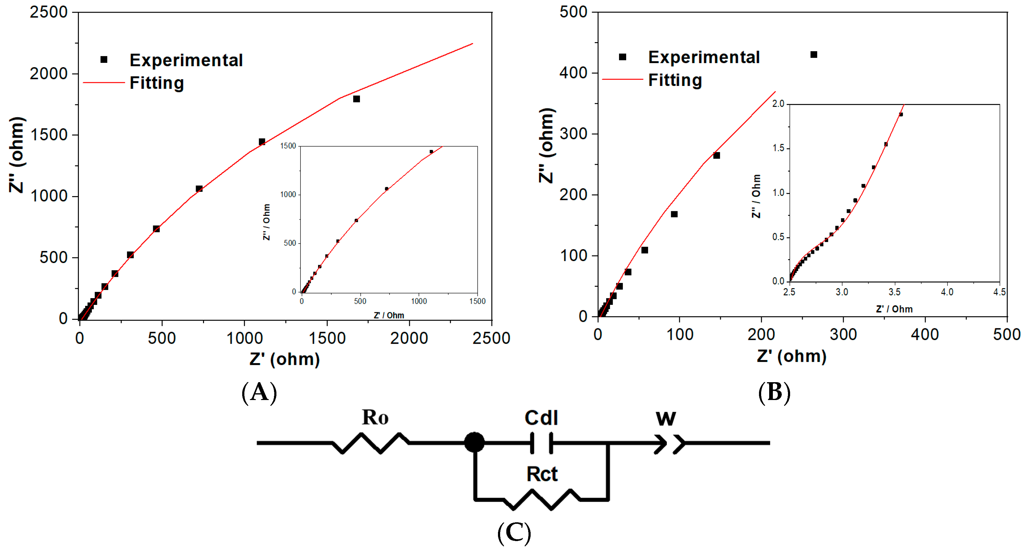
The electrochemical impedance spectrum is usually applied to analyze the charge transfer resistance in the high frequency range and the diffusion impedance of the designed composite electrode in the low frequency range. Figure 8A–C show the electrochemical impedance spectra of CNF-O/PPY and CNF/PPY electrodes and an equivalent circuit modeling diagram. Table 2 lists the fitting parameter values of electronic elements in the equivalent circuit modeling diagram. The equivalent circuit modeling includes four electronic elements, which are assigned to the charge transfer resistance (Rct), ohmic resistance (Ro), Warburg impendence (W), and double-layer capacitance (Cdl). The CNF-O/PPY reveals much lower Rct and Ro values than CNF/PPY, implying a more feasible charge transfer and lower ohmic resistance than CNF/PPY. The CNF-O/PPY also reveals a lower W value and a higher Cdl value than CNF/PPY. More feasible electrolyte ion diffusion in the CNF-O/PPY electrode causes its lower diffusion resistance and capacitive impedance as well. CNF-O/PPY accordingly achieves higher electrochemical double layer capacitance performance than a normal CNF/PPY electrode. The EIS measurement results of CNF-O/PPY and CNF/PPY agree with the above DFT-based modeling calculation results. So, the electrochemical impendence spectrum measurement discloses that CNF-O/PPY exhibits a lower charge transfer resistance (0.097 Ω), a lower ohmic resistance (0.336 Ω), a lower Warburg impedance (317 Ω), and a higher double-layer capacitance (0.113 mF) than CNF/PPY (1.419 Ω, 9.668 Ω, 7865 Ω, 0.015 mF), indicating higher reactivity of CNF-O/PPY. Lower ohmic resistance, lower Warburg impedance, more feasible charge transfer, and more electrolyte diffusion contribute to improving the electrochemical capacitance performance of CNF-O/PPY. So, these results prove the superior electroactivity and capacitance of the CNF-O/PPY electrode than the CNF/PPY electrode.
4. Conclusions
Well-controlled epoxy and hydroxyl groups containing carbon nanofibers are synthesized as the substrate material, and the conductive polypyrrole is synthesized as the electroactive material. Polypyrrole is used to modify the activated carbon nanofibers, forming the well-designed CNF-O/PPY electrode. Theoretical molecular modeling calculations and experimental measurements are adopted to investigate the oxygen activation effect of carbon nanofibers interacting with PPY. The response current and electrochemical capacitance are adopted as the testing indicators for electroactivity evaluation. The CNF undergoes hydrothermal oxidation treatment to form CNF-O. The oxygen activation effect of carbon nanofibers on their electronic and electrochemical properties is investigated through the interfacial interaction between CNF-O and PPY. Theoretical molecular modeling calculations disclose that CNF-O/PPY exhibits a lower electronic bandgap (0.64 eV), a higher density of states (10.039 states/eV), and a lower HOMO–LUMO molecular orbital energy gap (0.077 eV) than CNF/PPY (1.56 eV, 7.946 states/eV, 0.112 eV), presenting a superior electronic conductivity of CNF-O/PPY. The Mulliken population and charge distribution show that the intensified interfacial interaction is established in CNF-O/PPY rather than CNF/PPY. The cyclic voltammogram measurement discloses that the specific capacitance is determined to be 57.6~24.2 mF g−1 for the CNF/PPY electrode and 221.1~112.2 mF g−1 for the CNF-O/PPY electrode at scan rates of 5~200 mV s−1. The electrochemical impendence spectrum discloses that CNF-O/PPY exhibits much lower Rct (0.097 Ω), lower Ro (0.336 Ω), lower W (317 Ω), and much higher Cdl (0.113 mF) than CNF/PPY (1.419 Ω, 9.668 Ω, 7865 Ω, 0.015 mF). These experimental results are in accordance with the molecular modeling calculation results. The CNF-O/PPY presents superior interfacial interaction than CNF/PPY, contributing to higher electronic conductivity properties and higher electrochemical capacitance performance. Both theoretical and experimental investigations prove the promotive oxygen activation effect of CNF could improve the electronic and electrochemical properties of CNF-O/PPY.
Author Contributions
Conceptualization, Y.X.; software, Y.X. and Y.W.; formal analysis, Y.X.; investigation, Y.X.; data curation, L.W. and J.L.; writing—original draft preparation, Y.X.; writing—review and editing, Y.X. All authors have read and agreed to the published version of the manuscript.
Funding
This research work is supported by the Science and Technology Program of Suzhou City (SYG202342), China, and the Big Data Computing Center of the Southeast University, China.
Data Availability Statement
Data are available upon request.
Conflicts of Interest
The authors declare no conflict of interest.
References
- Yadav, D.; Amini, F.; Ehrmann, A. Recent advances in carbon nanofibers and their applications—A review. Eur. Polym. J. 2020, 138, 109963. [Google Scholar] [CrossRef]
- Altin, Y.; Bedeloglu, A.C. Flexible carbon nanofiber yarn electrodes for self-standing fiber supercapacitors. J. Ind. Text. 2022, 51 (Suppl. S3), 4254S–4267S. [Google Scholar] [CrossRef]
- Kundu, A.; Shetti, N.P.; Basu, S.; Mondal, K.; Sharma, A.; Aminabhavi, T.M. Versatile Carbon Nanofiber-Based Sensors. ACS Appl. Bio. Mater. 2022, 5, 4086–4102. [Google Scholar] [CrossRef]
- Soltani, S.; Khanian, N.; Shojaei, T.R.; Choong, T.S.Y.; Asim, N.; Zhao, Y. Recent trends in the design and engineering of incorporated carbon nanofiber nanocomposites and their advanced applications-A review. Mater. Chem. Phys. 2022, 286, 19. [Google Scholar] [CrossRef]
- Tan, S.; Li-Oakey, K.D. Effect of Structural Orientation on the Performance of Supercapacitor Electrodes from Electrospun Coal-Derived Carbon Nanofibers (CCNFs). J. Electrochem. Soc. 2019, 166, A3294. [Google Scholar] [CrossRef]
- da Silva, L.M.; de Lima Almeida, D.A.; Oishi, S.S.; Couto, A.B.; Ferreira, N.G. Constituent material influence on the electrochemical performance and supercapacitance of PAni/diamond/CF composite. Mater. Sci. Eng. B 2018, 228, 249–260. [Google Scholar] [CrossRef]
- Sassin, M.B.; Hoffmaster, A.N.; Österholm, A.M.; Lo, C.K.; Ko, J.S.; Reynolds, J.R.; Long, J.W. Integrating Solution-Processable Conducting Polymers in Carbon Fiber Paper: Scalable 3D Electrodes for Redox-Based Supercapacitors. ACS Appl. Polym. Mater. 2020, 2, 3234–3242. [Google Scholar] [CrossRef]
- Cherusseri, J.; Sambath Kumar, K.; Pandey, D.; Barrios, E.; Thomas, J. Vertically Aligned Graphene–Carbon Fiber Hybrid Electrodes with Superlong Cycling Stability for Flexible Supercapacitors. Small 2019, 15, 1902606. [Google Scholar] [CrossRef]
- Levitt, A.S.; Alhabeb, M.; Hatter, C.B.; Sarycheva, A.; Dion, G.; Gogotsi, Y. Electrospun MXene/carbon nanofibers as supercapacitor electrodes. J. Mater. Chem. A 2019, 7, 269–277. [Google Scholar] [CrossRef]
- Park, M.Y.; Kim, J.-H.; Kim, D.K.; Kim, C.G. Perspective on Carbon Fiber Woven Fabric Electrodes for Structural Batteries. Fiber Polym. 2018, 19, 599–606. [Google Scholar] [CrossRef]
- Xie, Y. Electrochemical Performance of Polyaniline Support on Electrochemical Activated Carbon Fiber. J. Mater. Eng. Perform. 2022, 31, 1949–1955. [Google Scholar] [CrossRef]
- Xie, Y. Electrochemical and hydrothermal activation of carbon fiber supercapacitor electrode. Fiber Polym. 2022, 23, 10–17. [Google Scholar] [CrossRef]
- Moosburger-Will, J.; Bauer, M.; Laukmanis, E.; Horny, R.; Wetjen, D.; Manske, T.; Schmidt-Stein, F.; Töpker, J.; Horn, S. Interaction between carbon fibers and polymer sizing: Influence of fiber surface chemistry and sizing reactivity. Appl. Surf. Sci. 2018, 439, 305–312. [Google Scholar] [CrossRef]
- Lee, J.Y.; Kim, B.J. Surface-Modified Activated Carbon Fibers by a Facile Microwave Technique for Enhancing Hydrocarbon Adsorption. Environments 2023, 10, 14. [Google Scholar] [CrossRef]
- Wang, Y.B.; Li, H.; Cui, B.W.; Xu, X.D.; Wang, Y.X. Simple Mixed-Acid-Treated Carbon Fiber Electrodes with Oxygen-Containing Functional Groups for Flexible Supercapacitors. J. Compos. Sci. 2023, 7, 15. [Google Scholar] [CrossRef]
- Qin, J.J.; Wang, C.G.; Lu, R.J.; Su, S.S.; Yao, Z.Q.; Zheng, L.B.; Gao, Q.; Wang, Y.X.; Wang, Q.F.; Wei, H.Z. Uniform growth of carbon nanotubes on carbon fiber cloth after surface oxidation treatment to enhance interfacial strength of composites. Compos. Sci. Technol. 2020, 195, 10. [Google Scholar] [CrossRef]
- Lee, Y.G.; An, G.H. Surface Functionalization of Carbon Fiber for High-Performance Fibrous Supercapacitor. Kor. J. Mater. Res. 2022, 32, 107–113. [Google Scholar] [CrossRef]
- Jung, H.Y.; Roh, S.H. Carbon Nanofiber/Polypyrrole Nanocomposite as Anode Material in Microbial Fuel Cells. J. Nanosci. Nanotechnol. 2017, 17, 5830–5833. [Google Scholar] [CrossRef]
- Dumanlı, A.G.; Erden, A.; Yürüm, Y. Development of supercapacitor active composites by electrochemical deposition of polypyrrole on carbon nanofibres. Polym. Bull. 2012, 68, 1395–1404. [Google Scholar] [CrossRef]
- Jain, R.; Jadon, N.; Pawaiya, A. Polypyrrole based next generation electrochemical sensors and biosensors: A review. TrAC Trends Anal. Chem. 2017, 97, 363–373. [Google Scholar] [CrossRef]
- Maduraiveeran, G.; Sasidharan, M.; Ganesan, V. Electrochemical sensor and biosensor platforms based on advanced nanomaterials for biological and biomedical applications. Biosens. Bioelectron. 2018, 103, 113–129. [Google Scholar] [CrossRef] [PubMed]
- Zhu, H.; Xie, Y. Electrochemical performance of bridge molecule-reinforced activated carbon fiber-m-aminobenzenesulfonic acid-polyaniline for braidable-supercapacitor application. Chem. Eng. J. 2023, 478, 147416. [Google Scholar] [CrossRef]
- Aryal, K.P.; Jeong, H.K. Electrochemical detection of ascorbic acid with chemically functionalized carbon nanofiber/beta-cyclodextrin composite. Chem. Phys. Lett. 2020, 757, 137881. [Google Scholar] [CrossRef]
- Yang, T.; Tian, X.D.; Song, Y.; Wu, S.J.; Wu, J.R.; Liu, Z.J. Oxygen-doped carbon nanofiber nonwovens as an effective interlayer towards accelerating electrochemical kinetics for lithium-sulfur battery. Appl. Surf. Sci. 2023, 611, 155690. [Google Scholar] [CrossRef]
- Cuevas-Muñiz, F.M.; Gurrola, M.P.; Tellez-Vázquez, O.; Esparza, R.; Guerra-Balcázar, M.; Arriaga, L.G.; Ledesma-García, J. Correlation between theoretical data and experimental selective properties of PtAg core-shell nanoparticles for oxygen reduction reactions. Int. J. Hydrogen Energy 2015, 40, 17284–17290. [Google Scholar] [CrossRef]
- Xie, Y. Simulation Calculation Verification of Graphene Oxide-Decorated Silver Nanoparticles Growing on Titania Nanotube Array as SERS Sensor Substrate. Chemosensors 2022, 10, 507. [Google Scholar] [CrossRef]
Figure 1.
Overall view and magnified view of FESEM images of (A) carbon nanofibers of CNF and (B) oxygen-activated carbon nanofibers of CNF-O.
Figure 1.
Overall view and magnified view of FESEM images of (A) carbon nanofibers of CNF and (B) oxygen-activated carbon nanofibers of CNF-O.
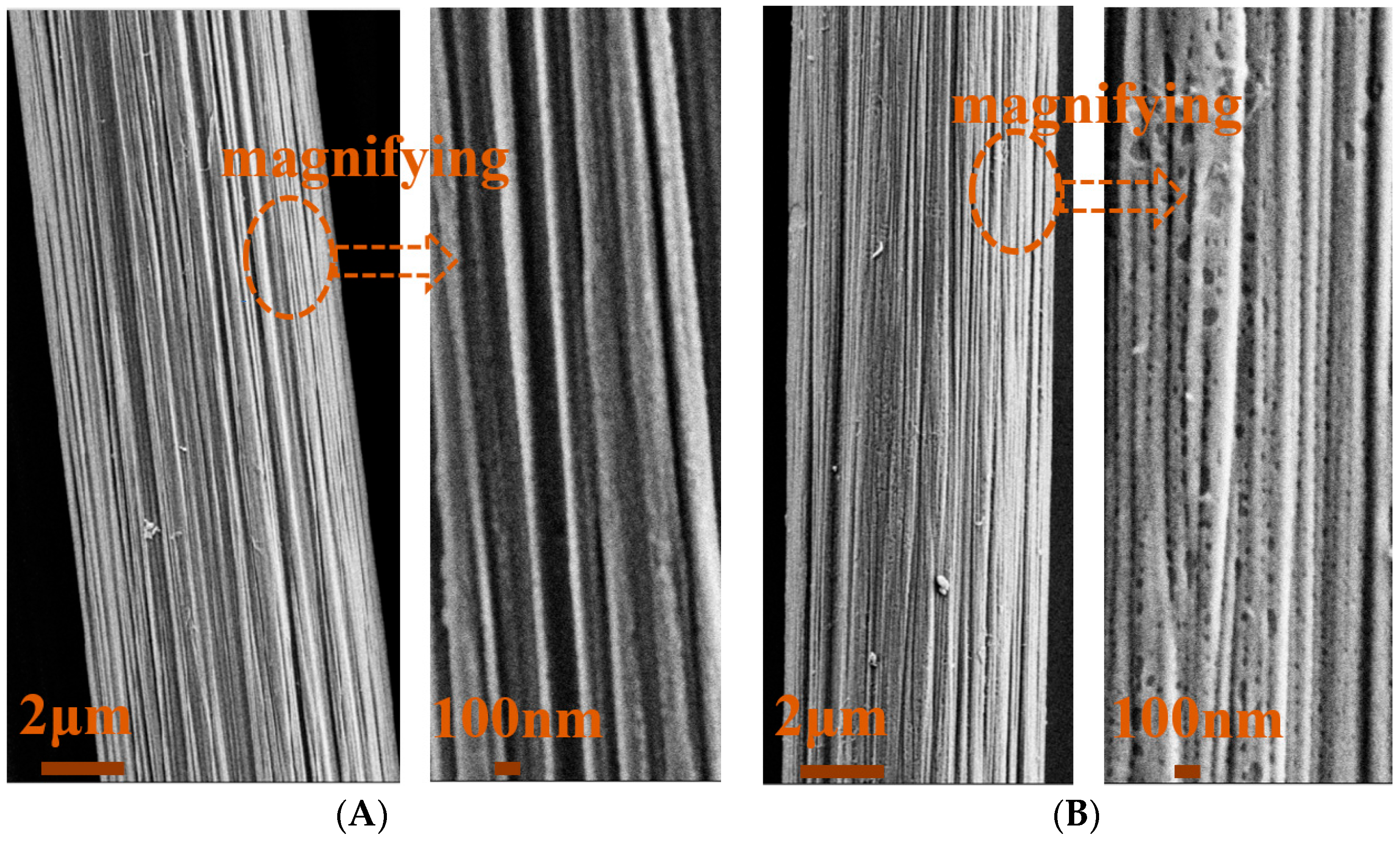
Figure 2.
(A,B) EDX spectra of CNF and CNF-O; (C) XPS spectrum with corresponding fitting curve of C 1s of CNF-O.
Figure 2.
(A,B) EDX spectra of CNF and CNF-O; (C) XPS spectrum with corresponding fitting curve of C 1s of CNF-O.
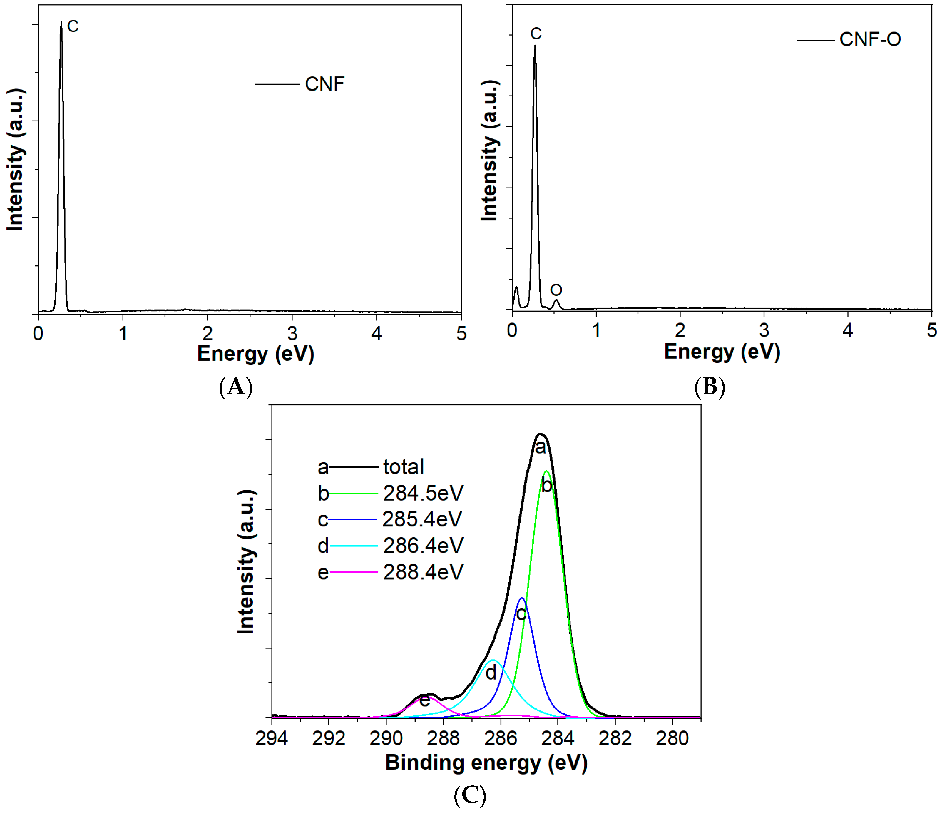
Figure 3.
(A,B) Periodic molecular modeling of CNF, CNF-O, CNF/PPY, and CNF-O/PPY; (C,D) charge density difference; and (E,F) Mulliken population charge of CNF/PPY and CNF-O/PPY.
Figure 3.
(A,B) Periodic molecular modeling of CNF, CNF-O, CNF/PPY, and CNF-O/PPY; (C,D) charge density difference; and (E,F) Mulliken population charge of CNF/PPY and CNF-O/PPY.
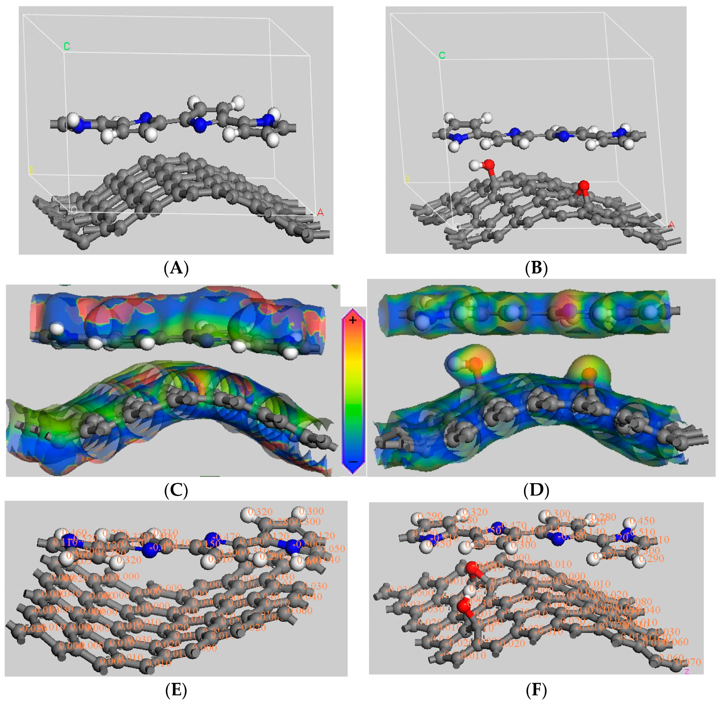
Figure 4.
Electronic bandgap curves of (A) CNF/PPY and (B) CNF-O/PPY.
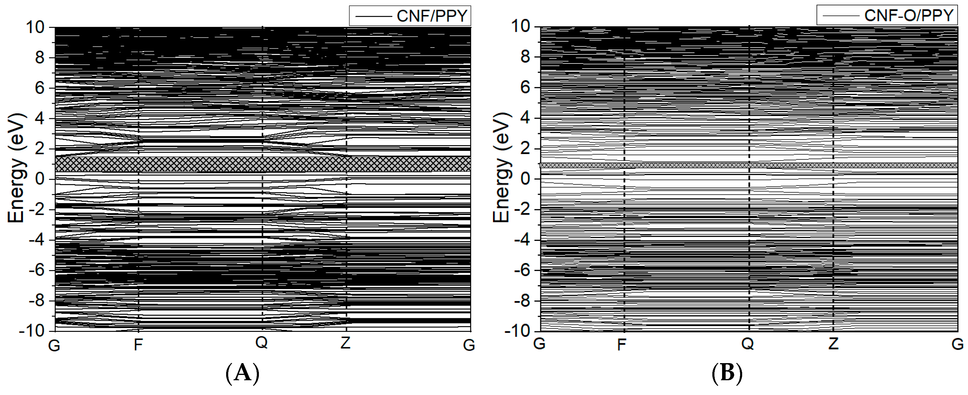
Figure 5.
Electronic density of states of (A) CNF/PPY and (B) CNF-O/PPY.

Figure 6.
HOMO and LUMO electron density distribution of (A,C) CNF/PPY and (B,D) CNF-O/PPY.
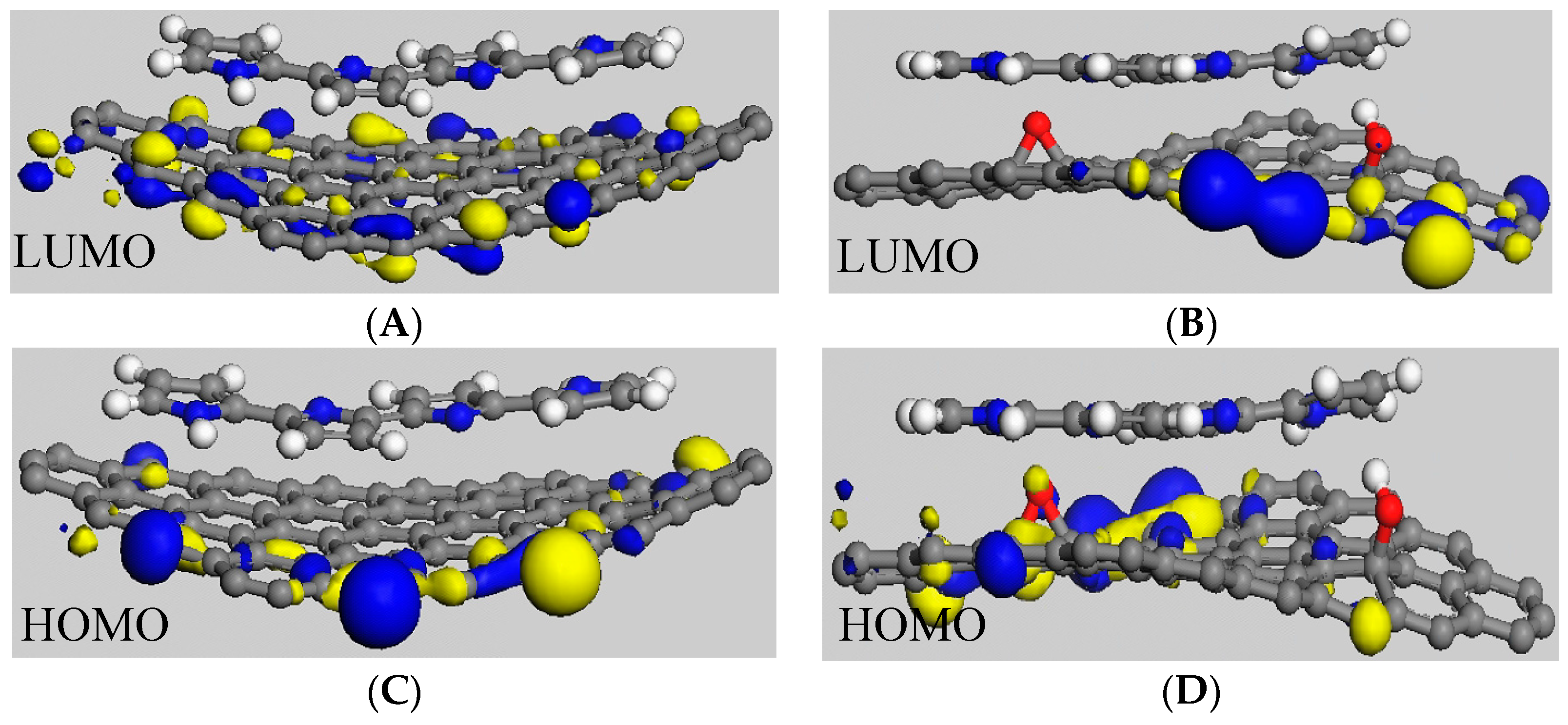
Figure 7.
(A,B) CV curves and (C) corresponding specific capacitance in terms of response current density of CNF/PPY and CNF-O/PPY electrodes in 1.0 M LiClO4 at scan rates from 5 to 200 mV s−1.
Figure 7.
(A,B) CV curves and (C) corresponding specific capacitance in terms of response current density of CNF/PPY and CNF-O/PPY electrodes in 1.0 M LiClO4 at scan rates from 5 to 200 mV s−1.

Figure 8.
(A,B) Electrochemical impedance spectrum of CNF-O/PPY and CNF/PPY electrodes, and (C) equivalent circuit modeling diagram.
Figure 8.
(A,B) Electrochemical impedance spectrum of CNF-O/PPY and CNF/PPY electrodes, and (C) equivalent circuit modeling diagram.

Table 1.
Specific capacitance of CNF/PPY and CNF-O/PPY electrodes at scan rates from 5 to 200 mV s−1.
Table 1.
Specific capacitance of CNF/PPY and CNF-O/PPY electrodes at scan rates from 5 to 200 mV s−1.
| Scan Rate (mV s−1) | 200 | 100 | 50 | 20 | 10 | 5 |
|---|---|---|---|---|---|---|
| CNF/PPY (mF g−1) | 24.2 | 27.4 | 32.1 | 39.4 | 46.2 | 57.6 |
| CNF-O/PPY (mF g−1) | 112.2 | 123.5 | 136.1 | 156.3 | 177.7 | 221.1 |
Table 2.
Fitting parameter values of electronic elements in the equivalent circuit modeling diagram.
Table 2.
Fitting parameter values of electronic elements in the equivalent circuit modeling diagram.
| Electrodes | Cdl (mF) | Rct (Ω) | Ro (Ω) | W (Ω) |
|---|---|---|---|---|
| CNF-O/PPY | 0.113 | 0.097 | 0.336 | 317 |
| CNF/PPY | 0.015 | 1.419 | 9.668 | 7865 |
Disclaimer/Publisher’s Note: The statements, opinions and data contained in all publications are solely those of the individual author(s) and contributor(s) and not of MDPI and/or the editor(s). MDPI and/or the editor(s) disclaim responsibility for any injury to people or property resulting from any ideas, methods, instructions or products referred to in the content. |
© 2023 by the authors. Licensee MDPI, Basel, Switzerland. This article is an open access article distributed under the terms and conditions of the Creative Commons Attribution (CC BY) license (https://creativecommons.org/licenses/by/4.0/).
Share and Cite
MDPI and ACS Style
Xie, Y.; Wang, Y.; Wang, L.; Liang, J. Theoretical and Experimental Investigations of Oxygen Activation Effect of Carbon Nanofibers Interacting with Polypyrrole. Fibers 2024, 12, 4. https://doi.org/10.3390/fib12010004
AMA Style
Xie Y, Wang Y, Wang L, Liang J. Theoretical and Experimental Investigations of Oxygen Activation Effect of Carbon Nanofibers Interacting with Polypyrrole. Fibers. 2024; 12(1):4. https://doi.org/10.3390/fib12010004
Chicago/Turabian StyleXie, Yibing, Yiting Wang, Lijun Wang, and Jiawei Liang. 2024. "Theoretical and Experimental Investigations of Oxygen Activation Effect of Carbon Nanofibers Interacting with Polypyrrole" Fibers 12, no. 1: 4. https://doi.org/10.3390/fib12010004
Note that from the first issue of 2016, this journal uses article numbers instead of page numbers. See further details here.