
Innovative Flexural Repair Technique of Pre-Damaged T-Beams Using Eco-Friendly Steel-Fibre-Reinforced Geopolymer Concrete


1
Department of Civil Engineering, Al-Azhar University, Nasr City 11884, Cairo, Egypt
2
Department of Construction Engineering, Misr University for Science and Technology, 6th of October City 3236101, Giza, Egypt
*
Author to whom correspondence should be addressed.
Fibers 2024, 12(1), 3; https://doi.org/10.3390/fib12010003
Submission received: 17 September 2023
/
Revised: 8 December 2023
/
Accepted: 14 December 2023
/
Published: 26 December 2023
Abstract
:This paper presents an innovative flexural repair technique for pre-damaged reinforced concrete T-beams using eco-friendly steel-fibre-reinforced geopolymer concrete (SFRGPC). The study considers various parameters such as repair layer depth, location and configuration, and the use of additional reinforcement in one beam. The beams were preloaded to 50% of their ultimate flexural capacity. Extensive measurements were taken, including crack initiation and propagation, crack width, initial stiffness, load deflection, peak loads, ductility index, and strain values. The structural performance of the repaired T-beams under flexural loading was predicted using an analytical model. The repaired beams showed an increase in carrying capacity, stiffness, and ductility, but the failure mode was identical to the control samples. The study shows that SFRGPC shows great promise as a technique for not only repairing pre-damaged reinforced concrete beams but also for their strengthening. The best results were obtained with three-sided jackets with fibrous geopolymer concrete only, resulting in a load-carrying capacity increase of 25.8% compared to reference T-beams. The bonding between SFRGPC and existing concrete was effective, with no slippage or disintegration at the interface. The repaired beams’ structural behaviour and performance under flexural loads were successfully predicted using the analytical model, with a precision of about 98%.

1. Introduction
Over the last few years, interest in the rehabilitation and repair of reinforced concrete (RC) structures using innovative materials has increased as the premature degradation of RC structures exposed to severe environmental conditions has become an increasingly serious problem. Currently, the most recent technologies used to repair and strengthen RC elements can be summarised as, carbon-fibre-reinforced polymer (CFRP) bars [1,2,3], steel members [4,5], textile-reinforced concrete or mortar [6,7], ferrocement materials [8,9], fabric-reinforced cementitious matrix (FRCM) [10,11], ultra-high strength fibre-reinforced concrete (UHPFRC) [12,13,14], polyvinyl alcohol fibre reinforced geopolymer concrete (PVAFRGC) [15] and hooked-end steel fibre concretes [16]. All of the above jacketing techniques have proven to be viable alternatives to conventional RC jacketing.
The use of fibres allows for the synthesis of durable and efficient repair/strengthening material, which in turn enhances safety and extends the operating life of concrete structures. There are a variety of fibres available, such as steel, natural, and glass fibre. Steel fibre is the most commonly used material; since steel fibre has the potential for absorbing energy, it can be utilised in structures that are subjected to mechanical or dynamic forces under seismic or cyclical conditions [17,18,19].
Geopolymers are mainly synthesised of two main components: pozzolanic material and alkaline activator. Fly ash, slag, silica fume, as well as their mixtures, are all examples of waste/byproduct materials that may be employed as pozzolanic materials, which contain high amounts of silica and alumina substances [20,21,22]. Additionally, the presence of silica fume and fly ash as binding materials improves both matrix strength and workability [23] and also leads to higher density and more durable geopolymer concrete (GPC) [24]. On the other hand, the alkaline activator can be sodium- or potassium-based silicate and hydroxide activators. By combining both ingredients of geopolymer, the alkaline activator causes the release of silica and alumina in base materials and the recombination of these elements in a 3D matrix of the polymer [25].
The high durability of a geopolymer over conventional concrete has encouraged researchers to study its compatibility and applicability as a repair material for deteriorated concrete structures [26,27,28,29,30]. However, the use of fibrous geopolymer in such situations is still not covered to the authors’ knowledge. Many studies have covered the mechanical properties of fibrous GPC and the effect of fibre type, size, content, and distribution on such properties [31,32]. Aydin and Baradan [33] reported the mechanical performance of alkali-activated slag/silica fume mortars with steel fibres. Additionally, Cui et al. [34] focused on the bond of geopolymer concrete with ribbed steel bars. Khabaz [35] examined the bond efficiency of steel fibres with hooked ends compared to smooth and straight steel fibres in the matrix of concrete mixtures. Çelik et al. [36] studied the performance of fly ash-based geopolymer concrete containing micro silica fume with various ratios of lathe scraps of steel 37 and lengths ranging from 2 to 7 mm. The authors concluded that the optimum lathe scraps ratio was 1 vol% as it improved compressive, flexural, and splitting tensile strength by 25.7, 14.4, and 12%, respectively. Also, the effect of adding glass fibres to fly ash and basalt powder geopolymer concrete was studied by Çelik et al. [37]. The authors recommended using a mixture of 50% basalt powder as a replacement of fly ash, 12 molar sodium-based activator, and 12 mm length glass fibres with a ratio of 1–2%, as this mixture attained compressive strength exceeding 40 MPa. Another study concentrated on using steel wires from waste tires in fly ash and basalt powder-based geopolymer concrete. It was concluded that using waste wires with a ratio of 5% leads to enhancing both compressive and tensile strengths two-fold [38].
Additionally, geopolymers are considered more sustainable and durable than conventional concrete in resisting elevated temperatures due to their high thermal stability [39,40]. A typical issue is a deficiency of bond strength between the repair material and the existing concrete [30,41,42].
The use of high early-strength composite material as an innovative repair material for concrete structures was suggested by Jiang et al. [43]. The authors utilised a mixture of sulphoaluminate cement with silica fume, fly ash, and fibre volume ratio of 2%; they concluded that this material could reach about 67% of its 28-day flexural strength after only 3 h. Also, it was recommended that the substrate surface be roughened, and a 1–2 mm cement paste must be applied to improve the bond with the repair material. Al-Nsour et al. [44] proposed repairing beams using both basalt fibre-reinforced polymer bars and ropes. These elements were added in grooves on the bottom surface of the repaired beams and were filled with epoxy resin. The repaired beams restored about 88 to 127% of their bending capacity. Esmaeili et al. [45] utilised cast-in-situ and prefabricated basalt textile-reinforced concrete panels and connected these panels to the repaired beams using ultra-high-performance concrete. Then, the beams were tested under four points of cyclic loading. It was found that the flexural capacity of beams with prefabricated panels was higher than that of cast-in-situ panels. Moreover, the flexural capacity of beams retrofitted by five layers of basalt textile was increased by about 86% compared to the control specimen.
Although the repair materials and techniques of concrete structures vary vastly, the use of GPC as a repair material still needs to be thoroughly studied. Additionally, the use of fibres in combination with GPC as a repair material is still in its infancy. Moreover, the concerns about the compatibility of GPC and substrate structures need to be addressed.
In this study, the flexural behaviour of pre-damaged reinforced concrete T-beams repaired with SFRGPC was investigated while taking the SFRGPC layering depth and repair scheme into consideration. Before the repair process, the beams were preloaded to 50% of their ultimate flexural capacity. After the repair process, the beams were tested in bending until failure while observing the following parameters: the pattern of crack initiation and propagation, the width of the cracks, load–deflection, peak loads, and strain in steel bars. These findings were analysed to build an analytical model for predicting the performance of repaired beams with SFRGPC concrete.
2. Experimental Program
2.1. Material and Mechanical Properties
Fly ash (FA), ground granulated blast furnace slag (GGBS), undensified silica fume (USF), alkaline activator solutions, and fine aggregate (silica sand) are the key constituents of geopolymer concrete. The chemical components of FA, GGBS, and USF were determined by X-ray fluorescence analysis (XRF) [46,47], as shown in Table 1. Also, the chemical composition of the utilised cement (ordinary Portland cement grade 42.5 N) is shown in Table 1.
As an aggregate, silica sand with a maximum particle size of 600 µm was used, according to the BS882 standard [48]. The grain size distribution of raw materials is shown in Figure 1. The average particle size of FA, GGBS, and USF was 27 µm, 13.5 µm, and 7 μm, respectively. In this research, hook-ended steel fibres were employed as fibre reinforcement at a volume percentage of 2% in order to create a sustainable repair material for concrete constructions. The fibres have a length of 33 mm, a diameter of 0.75 mm, and an aspect ratio of 44, with mechanical properties of 1100 MPa tensile strength and 200 GPa Young’s modulus. The alkaline activator solution was a mixture of potassium silicate (K2SiO3) and potassium hydroxide (KOH) [49]. For preparing 1 litre of KOH solution with 16 M, an approximate ratio of 1 KOH: 1 H2O by mass was prepared, while the mass ratios of K2SiO3/KOH were maintained at 2.50. Figure 2 shows the photos of binder, KOH flakes, and steel fibres that were incorporated in synthesising the GPC.
To fabricate the repair material, many plain GPC batches were prepared with different ratios of the mixed ingredients. By testing these mixes in compression, the highest compressive strength mixture was adopted (73.5 MPa at 28 days for cylindrical samples with diameters of 100 mm and height of 200 mm), and the detailed composition of ingredients is given in Table 2. Afterward, different ratios of steel fibres were added to the plain mixture (1, 2, and 3%) by volume of concrete. It was found that the compressive strength was 78.5, 82.5, and 89.6 MPa, and the tensile splitting strength was 6.2, 8.6, and 11.2 MPa for fibres ratios of 1, 2, and 3%, respectively. Despite the fact that the fibre ratio of 3% resulted in the highest characteristics, the 2% fibre ratio was selected as the repair material and was coined as SFRGPC. The reason for discarding the 3% fibre ratio was that its mixing was not easy, and a number of its samples suffered from inconsistency and honeycombing, which meant less durability for the repair material.
The SFRGPC was mixed in a 210-L concrete mixer (Tiling/Plastering mixer). The mixer’s drum rotated at a rate of 28–30 revolutions per minute (rpm). The idea of choosing this mixer is to resemble the situation of repairing structures in remote areas where the available tools may be primitive to some extent. Figure 3 shows the mixing sequence for SFRGPC. Firstly, the solid components of the FA, GGBS, and USF were dry-mixed in the drum mixer for about three minutes, after which the fine aggregate (silica sand) was added for two minutes to guarantee the consistency of the mixture. Finally, the alkaline activator solution and steel fibres were added gradually over a period of 2 min, and the mixer was operated for a further 3 min, for a total mixing time of 10 min.
As a repair material, it is vital to have an adequate initial setting time and workability, so these properties were determined in accordance with ASTM C191 [50] and ASTM C230 [51], respectively. The mix utilised was highly workable and could readily pass through the reinforcement without compaction; nonetheless, the initial setting time at 20 ± 2 °C was approximately 45 min, and the measured flow was found to be 195 mm. The samples were cured at ambient temperature until the date of testing and treated with plastic film to prevent moisture loss. It is worth noting that the initial setting time of the repair material was measured by adding the alkaline solution to the drum mixer, so the left time for pouring, placing, and finishing procedures of SFRGPC was nearly 40 min, which was more than sufficient for the whole repair process. Moreover, it was found that increasing the molarity of the potassium hydroxide helps in the delay of the initial setting time of the SFRGPC matrix, and that was the reason for using such high molarity in this mixture (i.e., 16M).
The mechanical properties of SFRGPC encompassed compressive, indirect tensile, and flexural strength, which were evaluated using 3 replicants of cube samples (100 mm on a side), cylinders with a diameter of 100 mm and a height of 200 mm, and prisms (100 mm on a side, 100 mm height, and 500 mm in length), respectively.
The mean compressive strength at 28 days after casting was equal to 86.5 MPa. The average stress for splitting indirect tension was 8.60 MPa, as shown in Figure 4a. The experimental results in Figure 4b indicate strain-softening behaviour after the peak load. The load–deflection curve also demonstrated that when cracking began, the load reduced gradually as a result of fibre bridging until slippage occurred throughout the fibres and the geopolymer matrix. Moreover, the failure pattern for splitting tensile samples and flexural prisms is shown in Figure 5.
To evaluate the bonding behaviour between the normal-strength concrete substrate (with a 28-day cube compressive strength of 34.4 MPa) as an existing concrete and SFRGPC as a repair composite material, three normal-strength concrete cylindrical samples were prepared and tested in indirect tension. Afterward, only one-half of each sample was returned to the mould, and the SFRGPC fresh mix was poured. Figure 6 shows the composite samples for testing the cohesion between the repair material and the substrate concrete. These 3 samples were tested in indirect tension at the age of 28 days for repair material. The average tensile strength was about 2.3 MPa, which represents excellent bond strength, as depicted by Sprinkel and Ozyildirim [42].
2.2. Concrete T-Beam Geometry and Reinforcement
The study involved the construction of seven identical reinforced concrete T-beams, which were used to assess the effectiveness of SFRGPC as a novel repair material. The T-beams built for the study were cast from ordinary Portland reinforced concrete with a cube strength of 34.4 MPa. Figure 7 depicts the sizes of the beams, which have a total height of 350 mm and a width of 150 mm, as well as an 80 mm thick slab flange and a width of 400 mm. They were 2000 mm in total length, with a clear span length of 1800 mm.
The study focused on repairing T-beams using flexural approaches, with all beams designed to fail in flexural mode. Each beam had two deform bars, sized 16 mm in diameter and 2200 mm in length, installed on the tensile side with a characteristic yielding stress value of 600 MPa on the tensile side. The slab was also reinforced with an upper reinforcement of 4Ø8. To prevent shear failure, the shear span (600 mm)-to-depth ratio was selected to be 1.8, which falls between 1.5 and 2.5 to guarantee the close results between the experimental and the calculated flexural capacity of the beam under loading [52]. Also, Ø10 stirrups (590 MPa yield strength value) were arranged in the web at 125 mm intervals. The narrow distribution of stirrups proved to be more effective in enhancing the shear capacity of beams with a small shear span-to-depth ratio (i.e., 2.5) [52]. The ultimate strengths for the Ø16 and Ø10 bars were 800 MPa and 665 MPa, respectively. Finally, plastic spacers were used to ensure that the actual measured reinforcement cover after installation in the shutter met the required concrete reinforcement cover of 15 mm.
2.3. Repaired T-Beams with SFRGPC
2.3.1. Preparation of Concrete T-Beams
Figure 8 illustrates the wooden mould used for the T-beam specimens and the assembly of the steel reinforcement cage. The concrete components were mixed using a 210-L shear mixer (plastering/tilling mixer). The dry components were mixed for 2 min before the water was added, which was then gradually poured into the mixture. After adding the water, the mixture was further stirred for 3 min. Once the mixture reached the wet stage, a vibrator was used to compact the mixture after it was cast into the wooden mould.
2.3.2. Repair Techniques for Flexural
After the T-beams were subjected to pre-damage (50% of their ultimate flexural capacity), they were removed from the testing setup and turned over for repair preparation; the details of the repaired T-beams configuration are given in Table 3. It should be noted that these repair configurations were selected to resemble real-life repair schemes. For beams F2 to F4, the bottom layer of the beam was removed and replaced by SFRGPC with different depths. Beam F5 was occupied by additional steel in the SFRGPC repair layer. For beam F6, the repair layer was applied on the top side of the beam. This may look different from the common repair schemes, but it was adopted to simulate the situation that the lower floor is not accessible. Beam F7 presents the case of full encasement of the repaired beam by a 3-sided jacket.
2.3.3. Preparation of the Pre-Damaged T-Beams
The concrete was removed by using a chipping hammer. Once the desired depth was achieved, water was used to clean the interface before applying the repair material. For beam F7, roughening of the surface by scabbling techniques for a depth of 2–2.5 mm. The formwork was kept in place for 24 h after casting. After demoulding and overcoming the concerns of debonding, three techniques were adopted to avoid cracking resulting from differential shrinkage. First, the existing concrete at the interface was wetted prior to casting the SFRGPC. Second, a plastic film was placed over the geopolymer surface after casting to limit water evaporation. Third, the repaired material was kept moist for 28 days after de-moulding using burlap and plastic sheets, as shown in Figure 9 [53,54].
2.4. Mechanical Test Setup and Procedure
The experimental testing of the repaired T-beams was carried out under a four-point loading arrangement, with one end allowed to have hinge support while the other end had roller support, as shown in Figure 10. The loading was applied using a heavy steel beam (I-shape) on the top of the slab. A hydraulic jack, capable of carrying up to 500 kN, was used to incrementally increase the loading by 10 kN during the test procedure. LVDTs were utilised to measure deflection at the beam’s midspan during flexural testing, and their accuracy was 0.001 mm. Furthermore, crack width was also measured at the bottom chord of the beams. As can be seen, the LVDTs were fixed to the beams using metallic angles, which were glued onto the surface of concrete beams. Any rotation of the LVDTs during testing was considered negligible.
To evaluate the performance of beams repaired with SFRGPC layers, in addition to measuring the load and deflection at the half span length, measurements were also taken for the slip or differential movement at the interface, as shown in Figure 11. Furthermore, crack width propagation was also measured at the bottom chord of the beam for all cases and compared to control beams.
3. Analysis and Test Results
In this section, experimental test results from beams repaired by SFRGPC are presented and discussed. The method used to identify the failure mode of each test beam involved analysing the pattern of crack initiation and propagation, measuring the width of the cracks, determining the initial stiffness (P/Δ), observing load deflection, identifying peak loads, and measuring ductility (deflection values at ultimate load). These findings were then used to study the performance of preloaded beams that were repaired with SFRGPC, which was the focus of the experimental program. Figure 12a shows the crack pattern of beam F2 at the 50% loading stage and before the repair procedure. It was noted that the crack pattern for all beams at this level was nearly similar, and the visual inspection showed about 11 cracks that start from the bottom face of the beam and extend vertically near the lower face of the slab. Briefly, the failure pattern mode for all repaired T-beams is shown in Figure 12b.
3.1. Load–Deflection Behaviour
Figure 13 displays load–deflection performance for all the tested beams to evaluate and compare their respective effectiveness.
By inspecting Figure 13, it appears that the control beam (F1-CB) capacity was 310 kN, with a peak deflection of 25 mm. However, the peak load of F2, F3, and F4 was 337 kN, 350 kN, and 372.3 kN with an increase in load capacity of repaired beams compared to F1-CB by 8.7%, 12.9% and 20.1%, respectively, and higher ultimate deflection values of 31.23 mm, 29.08 mm, and 27.7 mm, respectively, indicating that the repaired beams were more ductile than F1-CB.
In beam F5, which is similar to F4 but with additional reinforcement on the tension side, the improvement in ultimate load reached about 56% and 30% in comparison to F1-CB and F4, respectively. It is obvious that embedding steel into repair material represents a very successful way of repairing concrete beams. However, it is important to note that the peak deflection was 28.5 mm, which depicts more ductile behaviour than F1-CB and F4. Furthermore, the repaired beam at the compression side (F6) has a peak load of 318.4 kN, which is relatively close to F1-CB and a higher deflection of approximately 33.1 mm than F1-CB. This higher deflection can be attributed to the degraded stiffness of the preloaded beam, which was not treated during the repair process, as the repair was on the compression side only.
The T-beam repaired with three-sided jackets (F7) had the highest capacity with fibres only, sustaining a maximum load of 390 kN; this represents a capacity increase of 25.8% in comparison to the control beam. Furthermore, its deflection was observed to be 30.5 mm. This value indicates the ductility of the beam, which refers to its ability to undergo significant deformation before failing. A high deflection value can be a desirable property in some situations, as it can help dissipate energy and prevent sudden and catastrophic failure.
3.2. Repaired Beams Initial Stiffness
The initial stiffness (P/Δ) of the repaired pre-damaged T-beams was significantly increased by the addition of layers of SFRGPC, as shown in Figure 14. The maximum initial stiffness was achieved by beams F4, F5, and F7, which had an initial stiffness of 51 kN/mm, representing an 18.6% increase compared to the initial stiffness of F1-CB. On the other hand, the repaired beams F2 and F3 achieved a slight increase in initial stiffness of about 2% and 7%, respectively, compared to the control beam F1-CB. It is worth noting that the repaired beam F6 on the compression side had lower stiffness due to the previous crack pattern at the preliminary stage of pre-damaged. Overall, the results indicate that the repaired beams with SFRGPC can effectively improve the initial stiffness and performance corresponding to peak loads.
3.3. Repaired Beams Ductility Index
The ductility index is calculated as the ratio of the deflection under peak load (Δp) to the deflection under yield load (Δy). It measures a beam’s ability to sustain inelastic deformation without significantly reducing its load-carrying capacity [55]. From Figure 15, it can be observed that the control beam F1-CB experienced a ductility index of 3.36. All repaired beams at the tensile side experienced a ductility index of 3.9 to 4.28, which is more than F1-CB by 16–27%. The repaired beam at the compression side F6 experienced a ductility index of 5.8, which is more than the control beam by 70%; this is attributed to the reduced value of beam deflection at the yield load in combination with the enhanced peak deflection due to the contribution of the fibrous repair material at compression side at the ultimate stage as it possesses higher compressive strength than OPC material.
3.4. Repaired Beams Crack Width
Figure 16 shows that the crack width at yield load for F1-CB was about 0.7 mm, while for all repaired beams, it was between 0.43 and 1.2 mm. The crack width at peak load for F1-CB was 5.1 mm, while for F2, F3, and F4 was 5.68, 4.6, and 4.75 mm, respectively. However, it increased by 66% for F5 and 20% for F7 due to their high carrying capacity. In the case of the F6, the crack width increased by 11% due to the preloading stage.
3.5. Measured Strains
Strain gauges were installed on the longitudinal reinforcement to show where the failure of the beam develops, as shown in Figure 17. The steel-yielding plateau is obvious for all beams except for F5. It may be comprehended that this additional bar, in conjunction with fibrous repair material, started to change the failure pattern of the beam from tension to compression failure.
Table 4 also shows a summary of the test results for the control T-beam and the repaired beams with SFRGPC. This includes the first crack load, deflection, and crack width for each beam tested, as well as a summary of the test results at the peak load. This table can be used to compare the enhancement ratio and type of failure mode of the control T-beams and the repaired T-beams. Also, a number of findings in Table 4 agreed with the work of Al-Majidi et al. [15]. The authors concluded that repairing RC beams using polyvinyl alcohol fibre reinforced geopolymer concrete (with repair layer thickness to depth ratio of 12.5 and 25%) leads to enhancement of the beams’ first crack and peak loads compared to the reference specimen.
The best performance was achieved with the construction of three-sided jackets with fibrous geopolymer concrete, resulting in a load-carrying capacity increase of 25.8% compared to the control beams. The first crack load was measured at 72.5 kN, and the crack width increased dramatically with the load, reaching 6.1 mm at the peak load. The stiffness of the repaired T-beams was improved by using three-sided jackets of SFRGPC in the tension zone.
Lastly, the results show that the repair beams had a different crack propagation pattern, with smaller widths and increasing stiffness and capacity. The effectiveness of flexure repairs by SFRGPC also varied with the degree of thickness and configuration of the SFRGPC. The research discovered that utilising a three-sided jacket or applying SFRGPC with 37.5% of the total beam depth on the tensile side may boost the capacity of the beams by a quarter without increasing the number of steel bars.
3.6. Interface Slippage Results of Repaired T-Beams
Figure 18 shows the slippage at the interface for different repair techniques; the maximum slippage was observed for F2, and the minimum slippage was observed for F6.
There are various techniques available for repairing concrete structures, and one of the earliest methods involves the replacement or addition of concrete layers. Although the repair element may be assumed to be monolithic in design calculations, in reality, there may be a slip at the interface between the existing and repair material due to the lack of compatibility. Therefore, it is crucial to enhance the shear strength at the interface to ensure that the shear stresses remain below the shear strength at the interface. Code provisions for the design of composite structures limit the values of interface slip based on the damage level [56]. For instance, the Greek retrofitting code sets the maximum accepted slip value at 0.2 mm for immediate occupancy level, 0.8 mm for significant damage or life safety level, and 1.5 mm for collapse prohibition performance level [57]. Additionally, the fib Bulletin 43 recommends a maximum interface slip of 0.2 mm for the serviceability limit state and 2.0 mm for the ultimate limit state [56].
Overall, the slip interface measurements for all the beams were small under the applied load. For example, in beam F2, the interface slip measurement was small, up to 0.2 mm, within an applied load of 265 kN, which was more than the yield load, and increased to 0.71 mm at the peak load of 337 kN. In beam F3, the slip at 0.2 mm was 284 kN, more than the yield load, and the peak slip was less than the life safety level of 0.8 mm. However, the recorded slip values for beams F4 and F6 were lower than 0.2 mm, which corresponded to the immediate occupancy level according to the Greek Code. Lastly, the slip values recorded for beam F5, which was repaired with an SFRGPC layer and steel bar, were significantly higher than those for F4, which had the same layer thickness but was less than the life safety level of 0.8 mm.
4. Analytical Modelling of Repaired T-Beams
In this section, analytical models are introduced to predict the structural behaviour of repaired T-beams using SFRGPC. These models have the potential to be valuable for designing repair systems in actual structures. The beam specimens were also analysed using an analytical model by utilising the internal stress distribution of their cross section. The purpose of developing the model was to estimate the ultimate capacity of the beams. This estimation was achieved by using material test results as input data and incorporating certain assumptions based on the bending theory of beams. In addition to the assumptions associated with beam bending theory, the following assumptions were considered: (i) The beam specimens exhibit monolithic behaviour, indicating a perfect bond between the concrete and SFRGPC. (ii) Material behaviours are governed by the laws of the material. (iii) A linear strain distribution existed across the beam’s cross section. By combining these assumptions with the principles of beam bending theory, an analytical model was established.
4.1. Repair Beam at Tensile Side Only
To determine the beam strength, it is necessary to achieve equilibrium between the internal forces and stress resultants for repair beams F2, F3, F4, and F5, as illustrated in Figure 19. According to the equivalent stress diagram, the compression stress in the compression zone is 0.85 fc’. The resultant force of the bottom steel bars (Tsteel) acts at the centre of the steel bars. Moreover, the contribution of the tensile stress in the SFRGPC (Ti,fibre) adds to this couple.
Therefore, the equilibrium equation of force and moment is given as follows when taking the contribution of the fibres into account:
Equilibrium of force is .
β = strength reduction factor equals 0.90 for hooked end steel fibre [60].
The tensile strength, fct,fibre was calculated according to Egyptian code [61] or Eurocode 2 (EN1992-1-131) [62] as illustrated in Equations (6) and (7) ([61,62]), respectively.
where fct,fibre is the direct tensile strength, MPa, and fct,splitt is the splitting tensile strength, MPa.
Equilibrium of moment is .
Hence, the predicted ultimate capacity is calculated by the following equation:
4.2. Repair Beam at Compression Side
Figure 21 shows the section dimensions and equivalent stress distribution for repair beam F6-37.5% ts-flange at the compression.
Hence, the predicted ultimate capacity is calculated by the following equation:
4.3. Repair Beam at Three Side Jacket
Equilibrium of moment is .
Hence, the predicted ultimate capacity is calculated by the following equation:
Table 5 summarises the findings of a comparison between the analytical model’s expected moment capacities for the beam specimens and the experimental test results. According to the results, there is excellent agreement between the predicted moment capacities and the measured results. The mean value of the agreement is 0.98, exhibiting a high degree of accuracy in the predictions. The standard deviation of 0.013 suggests a relatively small variation from the mean. The suggested models and repair strategy have been shown to be very accurate and applicable due to the close relationship between expected and experimental findings.
5. Conclusions
In this study, an innovative repair material (SFRGPC) was adopted. The repair material was synthesised using FA, slag, USF, silica sand, potassium-based alkaline activators, and steel fibres. A group of seven identical reinforced concrete beams was prepared and tested in bending following a four-point loading regime. The first beam was loaded to failure and was considered the reference beam. All the other beams were loaded to 50% of the ultimate capacity and were repaired using SFRGPC with different repair techniques: repair at the bottom side of the beam with different depths, use of additional bottom reinforcement in combination with SFRGPC, and repair at the upper layer of the beam. The following conclusions are drawn from the findings of this experimental study and the corresponding analytical model:
- The study’s findings suggest that SFRGPC has significant potential as a method for not only repairing damaged reinforced concrete beams but also as a strengthening material without changing beam dimensions.
- The repaired beams showed an increase in carrying capacity, stiffness, and ductility. Nonetheless, the failure mode identified in the repaired beams was identical to that of the control samples, which consisted of flexural fractures and mid-span crack propagation.
- The capacity of the repaired T-beams was significantly increased when steel bars were added to the SFRGPC layer, with a maximum load increase of 56% depending on the strength characteristics of the added steel bars.
- The best results (when using no additional steel) were obtained with three-sided jackets with fibrous geopolymer concrete, resulting in a load-carrying capacity increase of 25.8%, a 17% increase in ductility index, and an 18.6% increase in initial stiffness compared to the reference T-beams.
- SFRGPC helps the repaired T-beams to increase the first crack by 80% in the case of 3SJ compared to F1-CB.
- The bonding between SFRGPC and existing concrete was effective, as no slippage or disintegration at the interface of the two materials was observed during loading for all cases.
- The findings indicate the accuracy and effectiveness of the proposed model in predicting the flexural capacities of the repaired beams. However, the average prediction accuracy was 0.98, with a small standard deviation of 0.013.
- The suggested models and repair strategy have been shown to be very accurate and applicable due to the close relationship between expected and experimental findings under flexural loading conditions.
Finally, it is recommended that the proposed analytical models can be used by engineers in cases dealing with the same repair requirements, as these models’ accuracy reaches up to 98%. Also, the proposed three-sided jacket repair technique is recommended for its better results as it requires no additional steel. For the preparation of the beam itself, the roughing and cleaning of the beam surface before repair is a vital point. For the repair material itself, the thorough mixing of the ingredients to obtain a homogenous material is essential.
6. Recommendation for Future Studies
The validity of using SFRGPC as a repair material for reinforced concrete beams is promising. As this study concentrated on the mechanical characteristics of SFRGPC and its compatibility with a reinforced concrete substrate, it is recommended that future studies on SFRGPC repair material can cover its long-term compatibility with concrete structures, its resistance to aggressive media and corrosion potential of its fibres, its resistance to fire and elevated temperature scenarios, and its applicability to other reinforced concrete elements.
Author Contributions
Conceptualization, A.K., A.E.-W.E.-T., A.E.-S. and A.E.; methodology, A.E.-W.E.-T., A.E.-S. and A.E.; software, A.K. and A.E.; validation, A.K., A.E.-W.E.-T. and A.E.-S.; formal analysis, A.K., A.E.-W.E.-T., A.E.-S. and A.E.; investigation, A.K., A.E.-W.E.-T., A.E.-S. and A.E.; resources, A.K., A.E.-W.E.-T. and A.E.-S.; data curation, A.K., A.E.-W.E.-T., A.E.-S. and A.E.; writing—original draft preparation, A.K. and A.E.; writing—review and editing, A.E.; visualization, A.K. and A.E.; supervision, A.E.-W.E.-T., A.E.-S. and A.E.; project administration, A.E.-W.E.-T., A.E.-S. and A.E.; funding acquisition, no fund. All authors have read and agreed to the published version of the manuscript.
Funding
This research received no external funding.
Data Availability Statement
Data are contained within the article.
Conflicts of Interest
The authors declare no conflicts of interest.
References
- Morsy, A.M.; El-Tony, M.; El-Naggar, M. Flexural repair/strengthening of pre-damaged R.C. beams using embedded CFRP rods. Alex. Eng. J. 2015, 54, 1175–1179. [Google Scholar] [CrossRef]
- Khan, A.R.; Fareed, S. Behaviour of Reinforced Concrete Beams Strengthened by CFRP Wraps with and without End Anchorages. Procedia Eng. 2014, 77, 123–130. [Google Scholar] [CrossRef]
- Chalioris, C.E.; Kosmidou, P.-M.K.; Papadopoulos, N.A. Investigation of a new strengthening technique for RC deep beams using carbon FRP ropes as transverse reinforcements. Fibers 2018, 6, 52. [Google Scholar] [CrossRef]
- Demir, A.; Ercan, E.; Demir, D. Strengthening of reinforced concrete beams using external steel members. Steel Compos. Struct. 2018, 27, 453–464. [Google Scholar]
- Christidis, K.I.; Vougioukas, E.; Trezos, K.G. Strengthening of non-conforming RC shear walls using different steel configurations. Eng. Struct. 2016, 124, 258–268. [Google Scholar] [CrossRef]
- Triantafillou, T.; Papanicolaou, C. Shear strengthening of reinforced concrete members with textile reinforced mortar (TRM) jackets. Mater. Struct. 2006, 39, 93–103. [Google Scholar] [CrossRef]
- Gopinath, S.; Murthy, A.; Iyer, N.; Dharinee, R. Investigations on textile-reinforced concrete as cover for RC beams. Mag. Concr. Res. 2016, 68, 1040–1050. [Google Scholar] [CrossRef]
- Behera, G.; Rao, T.; Rao, C. Torsional behaviour of reinforced concrete beams with ferrocement U-jacketing—Experimental study. Case Stud. Constr. Mater. 2016, 4, 15–31. [Google Scholar] [CrossRef]
- Bansal, P.; Kumar, M.; Kaushik, S. Effect of wire mesh orientation on strength of beams retrofitted using Ferrocement jackets. Int. J. Eng. 2008, 2, 8–19. [Google Scholar]
- El-Maaddawy, T.; El Refai, A. Innovative Repair of Severely Corroded T Beams Using Fabric-Reinforced Cementitious Matrix. J. Compos. Constr. 2015, 20, 1–10. [Google Scholar] [CrossRef]
- Jabr, A.; El-Ragaby, A.; Ghrib, F. Effect of the fiber type and axial stiffness of FRCM on the flexural strengthening of RC beams. Fibers 2017, 5, 2. [Google Scholar] [CrossRef]
- Al-Osta, M.; Isa, M.; Baluch, M.; Rahma, M. Flexural behavior of reinforced concrete beams strengthened with ultra-high performance fiber reinforced concrete. Constr. Build. Mater. 2017, 134, 279–296. [Google Scholar] [CrossRef]
- Mohammed, T.; Bakar, B.; Bunnori, N.; Mohammed, T.J.; Bakar, B.H.A.; Bunnori, N.M. Torsional improvement of reinforced concrete beams using ultra high-performance fiber reinforced concrete (UHPFC) jackets—Experimental study. Constr. Build. Mater. 2016, 106, 533–542. [Google Scholar] [CrossRef]
- Murthy, A.; Karihaloo, B.; Priya, D. Flexural behavior of RC beams retrofitted with ultra-high strength concrete. Constr. Build. Mater. 2018, 175, 815–824. [Google Scholar] [CrossRef]
- Al-Majidi, M.; Lampropoulos, A.; Cundy, A.; Tsioulou, O.; Al-Rekabi, S. A novel corrosion resistant repair technique for existing reinforced concrete (RC) elements using polyvinyl alcohol fibre reinforced geopolymer concrete (PVAFRGC). Constr. Build. Mater. 2018, 164, 603–619. [Google Scholar] [CrossRef]
- Ali, W.; Ibrahim, A.; Ebead, U. Flexural Behavior of RC Beams Strengthened with Steel Fibers. Int. J. Appl. Eng. Res. 2020, 15, 468–480. [Google Scholar]
- Thomas, J.; Ramaswamy, A. Mechanical properties of steel fiber-reinforced concrete. J. Mater. Civ. Eng. 2007, 19, 85–92. [Google Scholar] [CrossRef]
- Barnett, S.J.; Lataste, J.F.; Parry, T.; Millard, S.G.; Soutsos, M.N. Assessment of fiber orientation in ultra high performance fiber reinforced concrete and its effect on flexural strength. Mater. Struct. 2010, 43, 1009–1023. [Google Scholar] [CrossRef]
- Soutsos, M.; Lampropoulos, A. Flexural performance of fibre reinforced concrete made with steel and synthetic fibres. Constr. Build. Mater. 2012, 36, 704–710. [Google Scholar] [CrossRef]
- Davidovits, J.; Orlinski, J. Geoplymeric reactions in archaeological cements and in modern blended cements. In Proceedings of the 1st International Conference on Geopolymer, Compiegne, France, 1–3 June 1988; Volume 1, pp. 93–106. [Google Scholar]
- Davidovits, J. Synthetic Mineral Polymer Compound of the Silicoaluminates Family and Preparation Process. U.S. Patent 4,472,199, 18 September 1984. [Google Scholar]
- Davidovits, J. Geopolymers: Inorganic polymeric new materials. J. Mater. Educ. 1994, 16, 91–139. [Google Scholar] [CrossRef]
- Meng, L.; Ding, Y.; Wei, L.L.J.; Li, M.; Wang, J.; Cao, S.; Liu, J. Study on dynamic properties of lightweight ultra-high performance concrete (L-UHPC). Constr. Build. Mater. 2023, 399, 132526. [Google Scholar] [CrossRef]
- Kumar, V.S.; Ganesan, N.; Indira, P.; Murali, G.; Vatin, N. Behaviour of Hybrid Fibre-Reinforced Ternary Blend Geopolymer Concrete Beam-Column Joints under Reverse Cyclic Loading. Polymers 2022, 14, 2239. [Google Scholar] [CrossRef]
- Smith, J.; Comrie, D. Geoplymeric building materials in third world countries. In Proceedings of the 1st International Conference on Geopolymer, Compiegne, France, 1–3 June 1988; Volume 1, pp. 89–92. [Google Scholar]
- Duxson, P.; Fernández-Jiménez, A.; Provis, J.L.; Lukey, G.C.; Palomo, A.; Van Deventer, J.S.J. Geopolymer technology: The current state of the art. J. Mater. Sci. 2007, 42, 2917–2933. [Google Scholar] [CrossRef]
- Provis, J.L. Geopolymers and other alkali activated materials: Why, how, and what? Mater. Struct. 2014, 47, 11–25. [Google Scholar] [CrossRef]
- Aziz, I.; Abdullah, M.; Heah, C.; Liew, Y. Behaviour changes of Ground granulated blast furnace slag geopolymers at high temperature. Adv. Cem. Res. 2020, 32, 465–475. [Google Scholar] [CrossRef]
- Inazumiet, S.; Inazawa, T.; Soralump, S.; Saiki, O. Assessment of potassium silicate based surface penetration materials with low viscosity in the repair of concrete structures. Int. J. Geomate 2017, 12, 163–170. [Google Scholar]
- Yuan, Y.; Marosszeky, M. Major factor influence the performance of structural repair. Evaluation and rehabilitation of concrete structures and innovations in design. In Proceedings of the ACI International Conference, Hong Kong, China, 2–6 December 1991. [Google Scholar]
- Sayyad, A.; Patankar, S. Effect of steel fibres and low calcium fly ash on mechanical and elastic properties of geopolymer concrete composites. Indian J. Mater. Sci. 2013, 23, 1–8. [Google Scholar] [CrossRef]
- Ganesan, N.; Indira, P.; Santhakumar, A. Engineering properties of steel fibre reinforced geopolymer concrete. Adv. Concr. Constr. 2013, 1, 305–318. [Google Scholar] [CrossRef]
- Aydın, S.; Baradan, B. The effect of fibre properties on high performance alkali-activated slag/silica fume mortars. Compos. Part B 2013, 45, 63–69. [Google Scholar] [CrossRef]
- Cui, Y.; Kayali, O.; Zhao, T.; Zhang, C. Bond Strength of Steel Bar and Plain or Fibre Reinforced Geopolymer Concrete. In Proceedings of the World Congress on Advances in Structural Engineering and Mechanics, Ulsan, Republic of Korea, 28 August–1 September 2017. [Google Scholar]
- Khabaz, A. Monitoring of impact of hooked ends on mechanical behaviour of steel fibre in concrete. Constr. Build. Mater. 2016, 113, 857–863. [Google Scholar] [CrossRef]
- Çelik, A.İ.; Özkılıç, Y.O.; Bahrami, A.; Hakeem, I.Y. Mechanical performance of geopolymer concrete with micro silica fume and waste steel lathe scraps. Case Stud. Constr. Mater. 2023, 19, e02548. [Google Scholar] [CrossRef]
- Çelik, A.İ.; Özkılıç, Y.O.; Bahrami, A.; Hakeem, I.Y. Effects of Glass Fiber on Recycled Fly Ash and Basalt Powder Based Geopolymer Concrete. Case Stud. Constr. Mater. 2023, 19, e02659. [Google Scholar] [CrossRef]
- Çelik, A.L.I.; Özkılıç, Y. Geopolymer concrete with high strength, workability and setting time using recycled steel wires and basalt powder. Steel Compos. Struct. 2023, 46, 689–707. [Google Scholar]
- Rickard, W.D.; Borstel, C.D.; van Riesse, A. The effect of pre-treatment on the thermal performance of fly ash geopolymers. Thermochim. Acta 2013, 573, 130–137. [Google Scholar] [CrossRef]
- Shaikh, F.A.; Hosan, A. Mechanical properties of steel fibre reinforced geopolymer concretes at elevated temperatures. Constr. Build. Mater. 2016, 114, 15–28. [Google Scholar] [CrossRef]
- Momayez, A.; Ehsani, M.; Ramezanianpour, A.; Rajaie, H. Comparison of methods for evaluating bond strength between concrete substrate and repair materials. Cem. Concr. Res 2005, 35, 748–757. [Google Scholar] [CrossRef]
- Sprinkel, M.; Ozyildirim, C. Evaluation of High Performance Concrete Overlays Placed on Route 60 over Lynnhaven Inlet in Virginia; Virginia Transportation Research Council: Charlottesville, VA, USA, 2000.
- Jiang, B.; Qian, Z.; Gu, D.; Pan, J. Repair concrete structures with high-early-strength engineered cementitious composites (HES-ECC): Material design and interfacial behavior. J. Build. Eng. 2023, 68, 106060. [Google Scholar] [CrossRef]
- Al-Nsour, R.; Abdel-Jaber, M.; Ashteyat, A.; Shatarat, N. Flexural repairing of heat damaged reinforced concrete beams using NSM-BFRP bars and NSM-CFRP ropes. Compos. Part C Open Access 2023, 12, 100404. [Google Scholar] [CrossRef]
- Esmaeili, J.; Khoshkanabi, S.; Andalibi, K.; Kasaei, J. An innovative method for improving the cyclic performance of concrete beams retrofitted with prefabricated basalt-textile-reinforced ultra-high performance concrete. Structures 2023, 52, 813–823. [Google Scholar] [CrossRef]
- ASTM Standard C114-00; Standard Test Methods for chemical Analysis of Hydraulic Cement. ASTM International: West Conshohocken, PA, USA, 2000.
- ASTM Standard C114-18; Standard Test Methods for chemical Analysis of Hydraulic Cement. ASTM International: West Conshohocken, PA, USA, 2018.
- BS 882:1992; Specification for Aggregates from Natural Sources for Concrete. British Standards Institute: London, UK, 1992.
- Potassium, G. Abo-Ghanema Fertilizers and Chemical Industries Company; Giza, Egypt, 2020. [Online]. Available online: https://www.dalil140.com/company?lng=en&n=169371-abo-ghanema-trade-agencies (accessed on 9 October 2023).
- ASTM C191-08; Standard Test Methods for Time of Setting Hydraulic Cement by Vicat Needle. ASTM International: West Conshohocken, PA, USA, 2008.
- ASTM C 230-08; Standard Specification for Flow Table for Use in Tests of Hydraulic Cement. ASTM International: West Conshohocken, PA, USA, 2008.
- Özkılıç, Y.O.; Aksoylu, C.; Arslan, M.H. Numerical evaluation of effects of shear span, stirrup spacing and angle of stirrup on reinforced concrete beam behaviour. Struct. Eng. Mech. Int. J. 2021, 79, 309–326. [Google Scholar]
- Beushausen, H.; Alexander, M. Failure mechanisms and tensile relaxation of bonded concrete overlays subjected to differential shrinkage. Cem. Concr. Res. 2006, 36, 1908–1914. [Google Scholar] [CrossRef]
- Dittmer, T.; Beushausen, H. The effect of coarse aggregate content and size on the age at cracking of bonded concrete overlays subjected to restrained deformation. Constr. Build. Mater. 2014, 69, 73–82. [Google Scholar] [CrossRef]
- Thirugnanam, G.; Govindan, P.; Sethratnam, A. Ductile behaviour of Slurry Infiltrated Fibrous Concrete (SIFCON) structural members. J. Struct. Eng. 2001, 28, 27–32. [Google Scholar]
- fib Bulletin. No 43; Structural Connections for Precast Concrete Buildings. International Federation for Structural Concrete (fib): Lausanne, Switzerland, 2008.
- GRECO. Greek Retrofitting Code (Final Version). In Greek Organization for Seismic Planning and Protection; Greek Ministry for Environmental Planning and Public Works: Athens, Greek, 2012. [Google Scholar]
- MARÍ, A.; Cladera, A.; Bairán, J.; Oller, E.; Ribas, C. Shear–flexural strength mechanical model for the design and assessment of reinforced concrete beams subjected to point or distributed loads. Front. Struct. Civ. Eng. 2014, 8, 337–353. [Google Scholar] [CrossRef]
- Cladera, A.; Marí, A.; Ribas, C.; Bairán, J.; Oller, E. Predicting the shear–flexural strength of slender reinforced concrete T and I shaped beams. Eng. Struct. 2015, 101, 386–398. [Google Scholar] [CrossRef]
- Qiu, M.; Shao, X.; Wille, K.; Yan, B.; Wu, J. Experimental Investigation on Flexural Behavior of Reinforced Ultra High Performance Concrete Low-Profile T-Beams. Int. J. Concr. Struct. Mater. 2020, 14, 20. [Google Scholar] [CrossRef]
- ECCS Committee. Egyptian Code for Design and Construction of Concrete Structures (Code N 203–Ministerial Decision 712/2017); Dokki Housing and Building National Research Center (HBRC): Giza, Egypt, 2017. [Google Scholar]
- EN 1992–1–1:2008; Eurocode 2, Design of Concrete Structures—Part 1-1: General Rules and Rules for Buildings. European Committee for Standardization: Brussels, Belgium, 2008.
Figure 1.
Particle size distribution: (a) silica sand; (b) fly ash; (c) GGBS; and (d) USF.

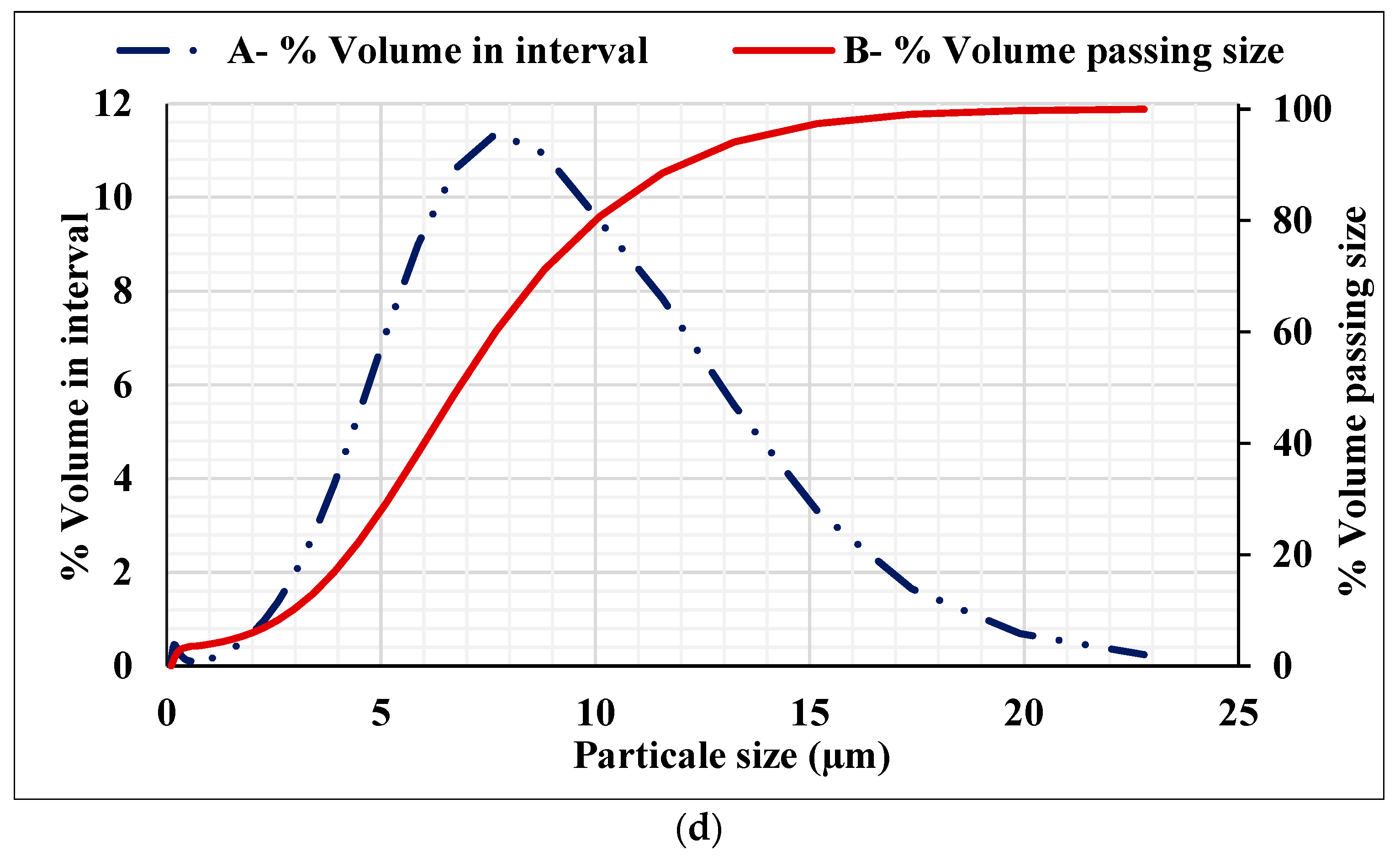
Figure 2.
GPC ingredients: (a) binder materials; (b) KOH flakes; (c) steel fibres.
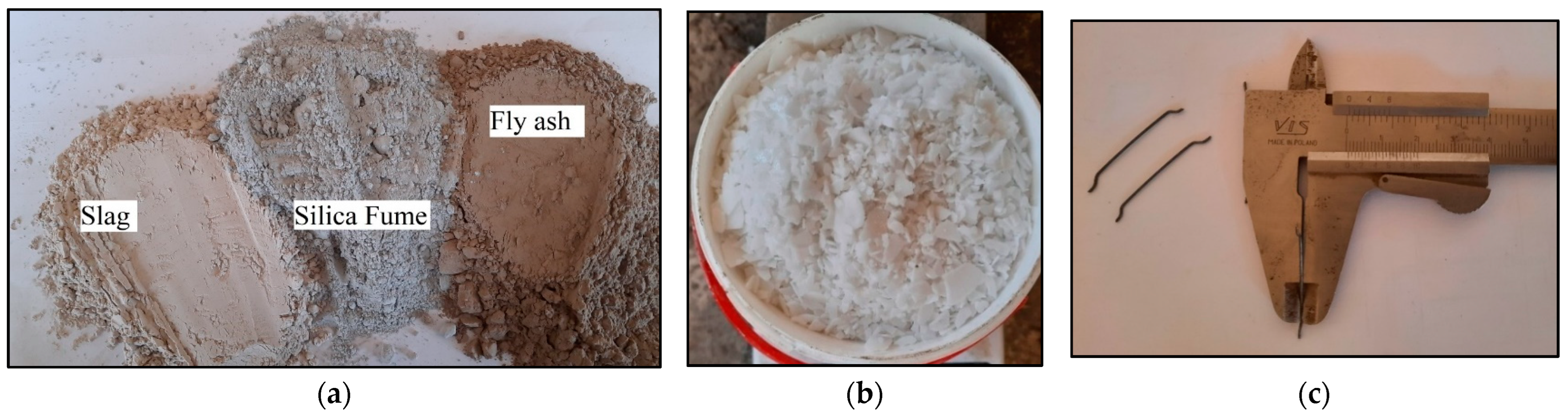
Figure 3.
SFRGPC mixing procedure.

Figure 4.
(a) Stress–strain curve for specimens with a 2% steel fibre. (b) Load versus mid-span deflection curve for SFRGPC prism beams.
Figure 4.
(a) Stress–strain curve for specimens with a 2% steel fibre. (b) Load versus mid-span deflection curve for SFRGPC prism beams.
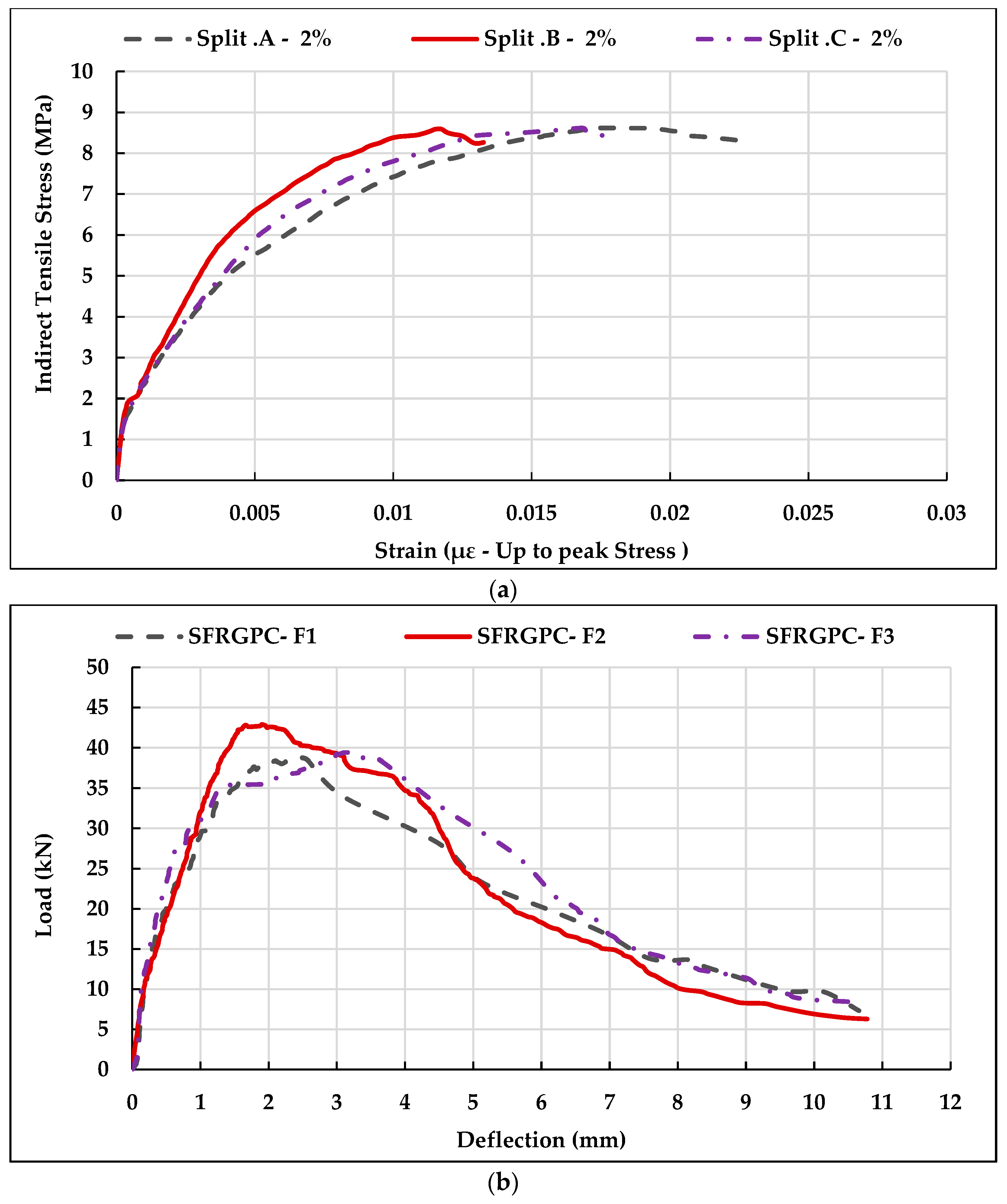
Figure 5.
Failure pattern: (a) split test; (b) flexural test.
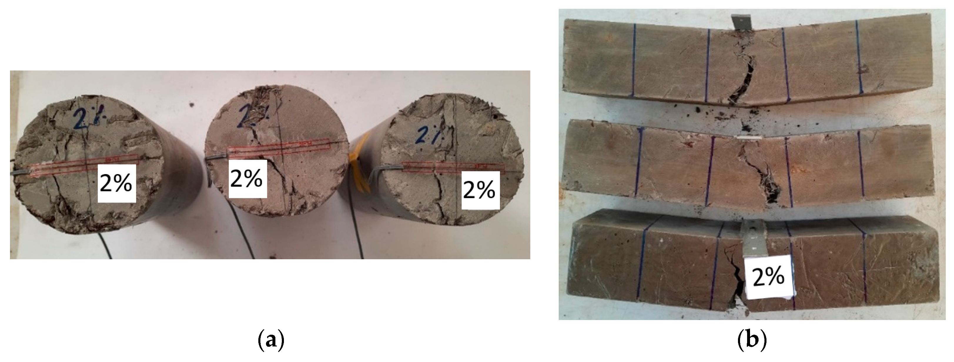
Figure 6.
Samples configuration and failure patterns of composite normal strength concrete substrate and SFRGPC repair material.
Figure 6.
Samples configuration and failure patterns of composite normal strength concrete substrate and SFRGPC repair material.
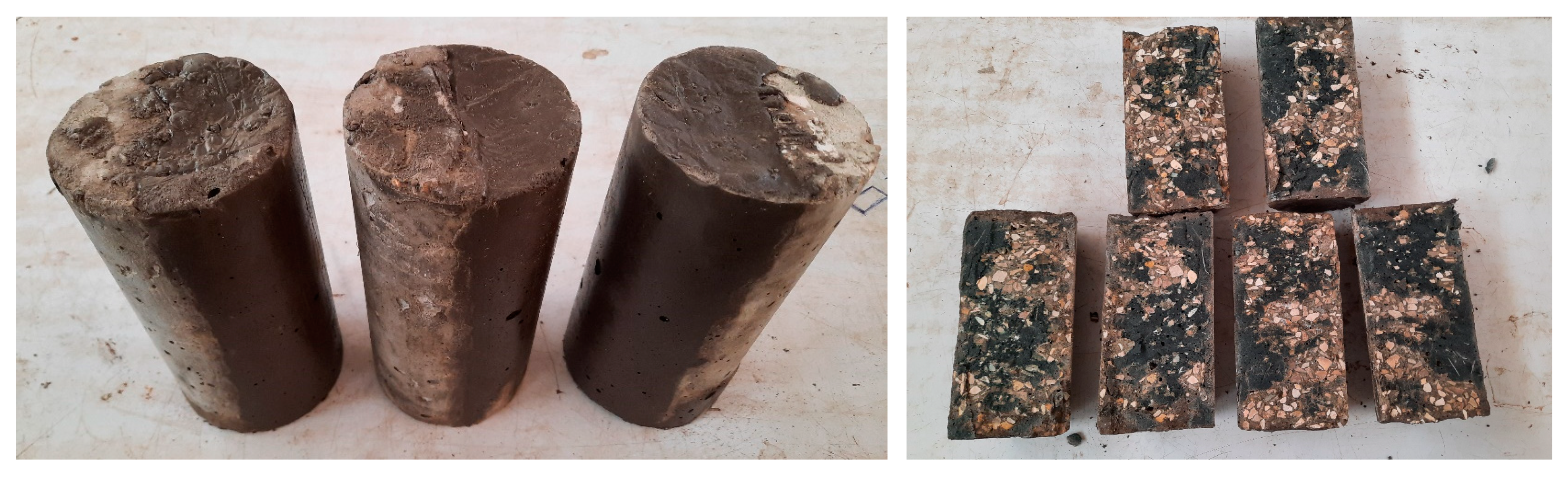
Figure 7.
Typical details and geometry of flexural T-beams.
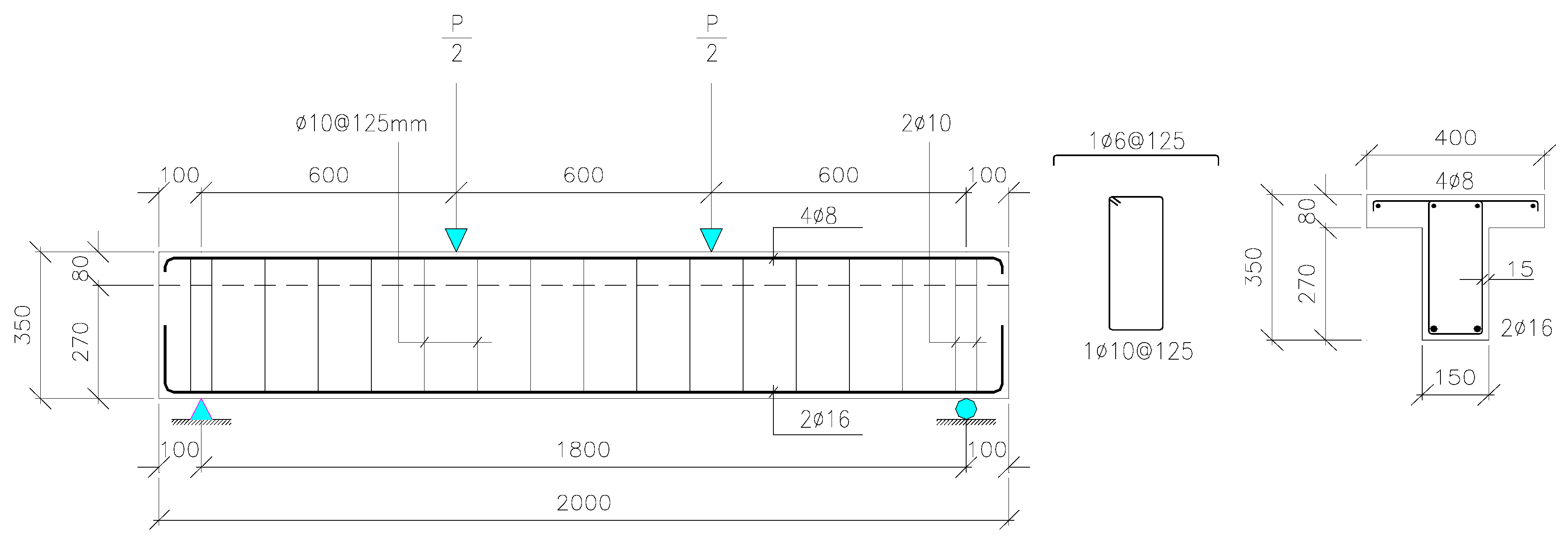
Figure 8.
Fabrication of T-beams: (a) installation of a steel cage inside a wooden mould; (b) concrete pouring.
Figure 8.
Fabrication of T-beams: (a) installation of a steel cage inside a wooden mould; (b) concrete pouring.
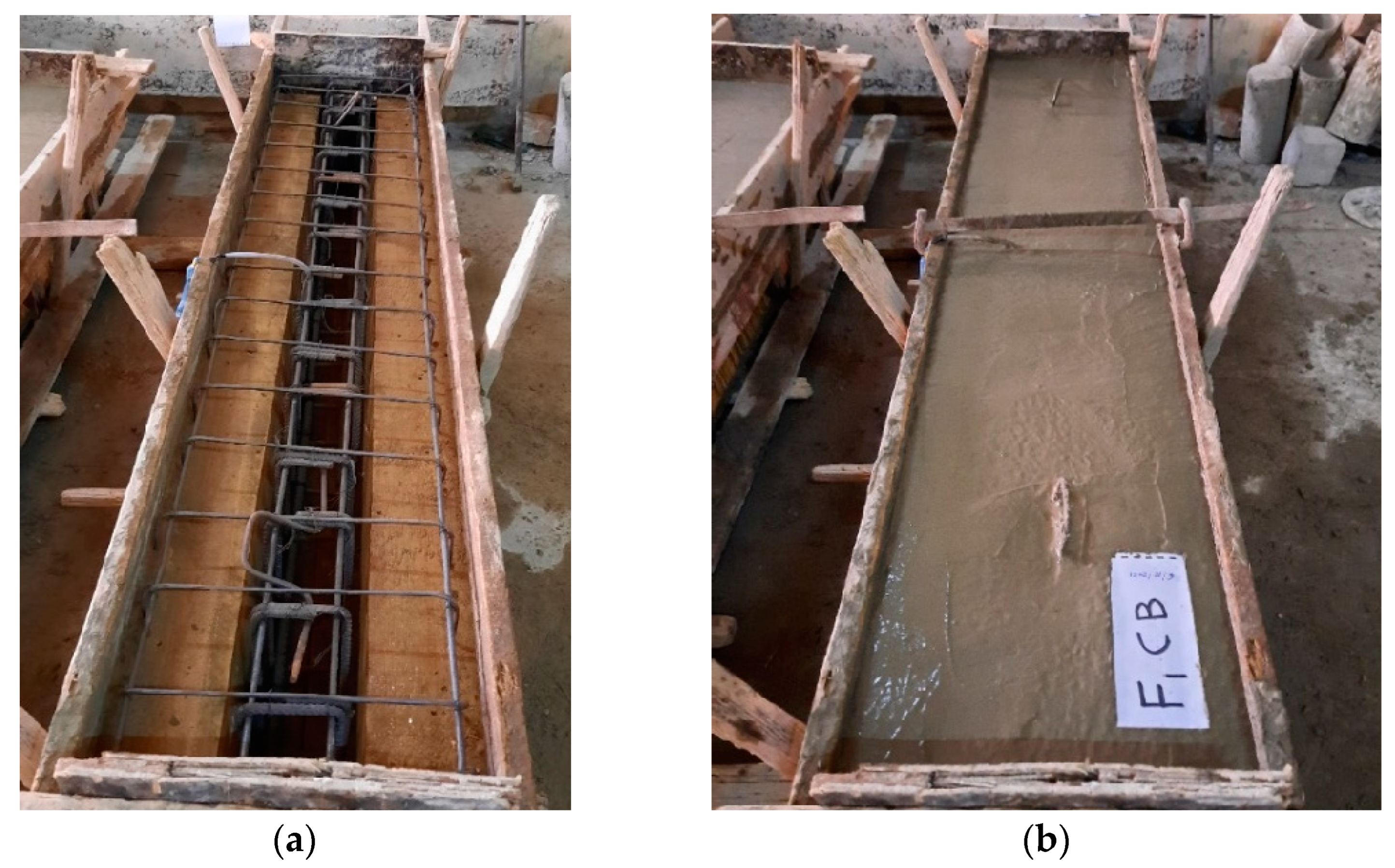
Figure 9.
Sample of casting repair materials and water spray curing.
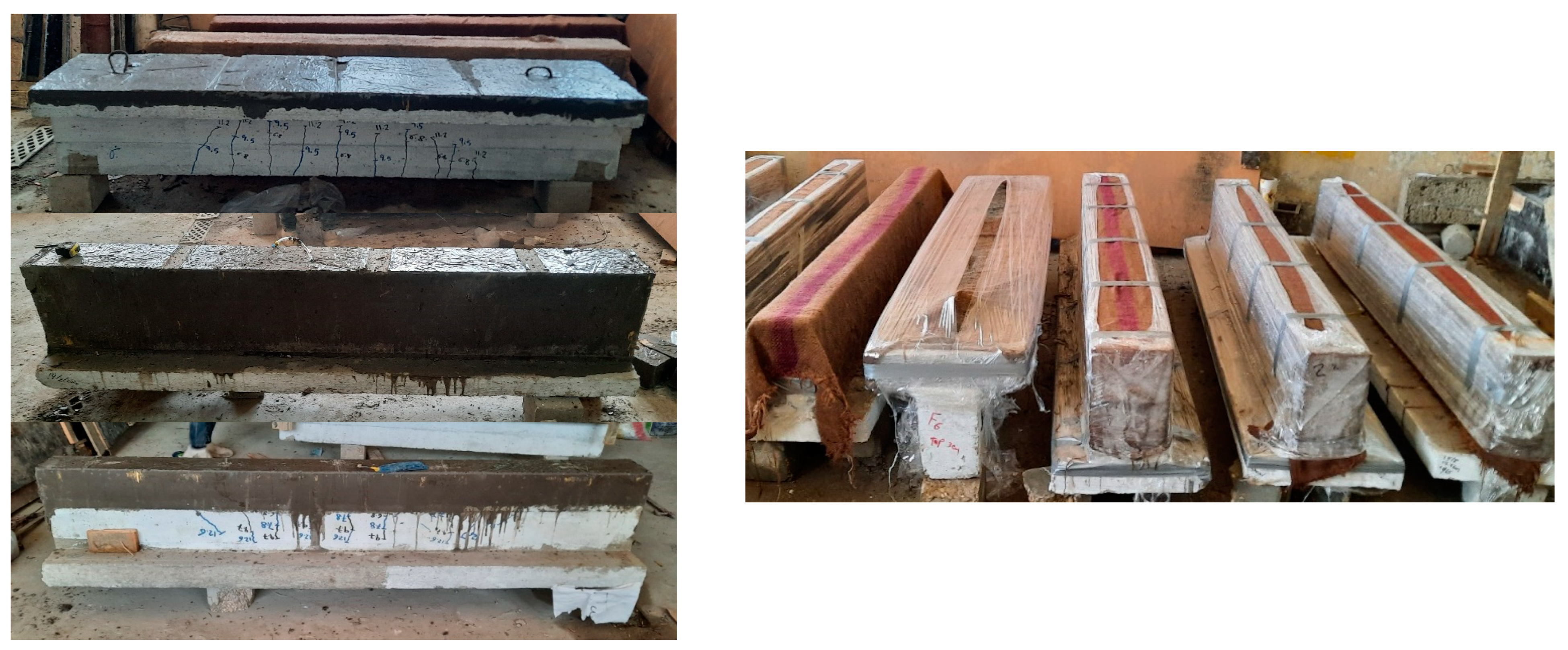
Figure 10.
Test setup for the control beams (flexural failure).

Figure 11.
Test setup for repaired T-beams.
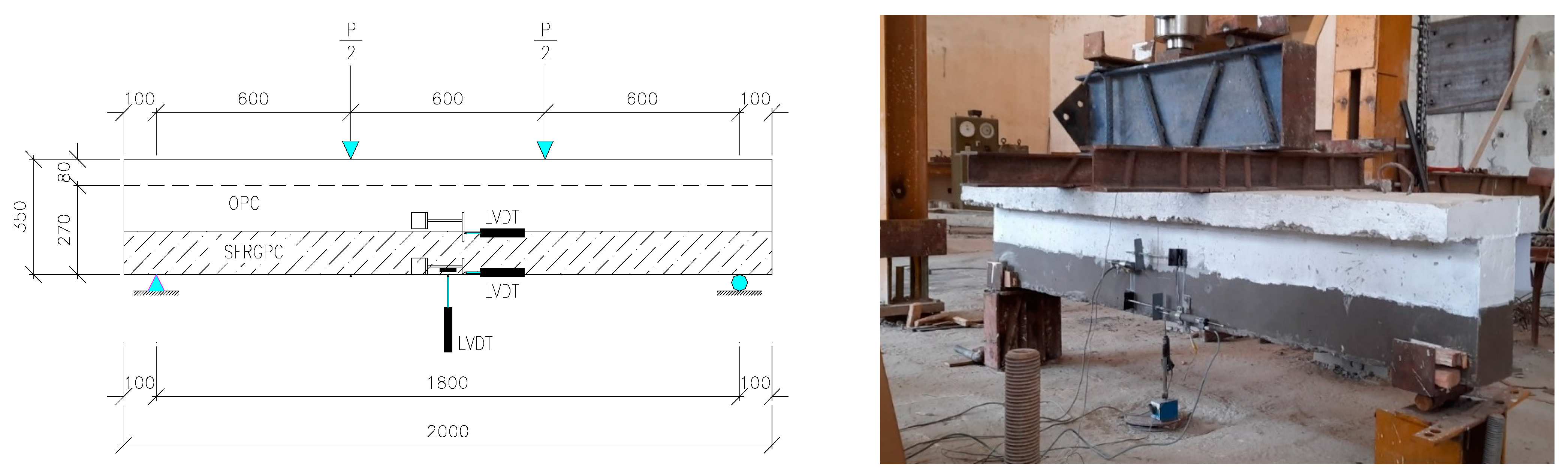
Figure 12.
(a) Crack pattern of an identical beam at 50% loading level; (b) crack pattern for repaired T-beams F2–F7.
Figure 12.
(a) Crack pattern of an identical beam at 50% loading level; (b) crack pattern for repaired T-beams F2–F7.
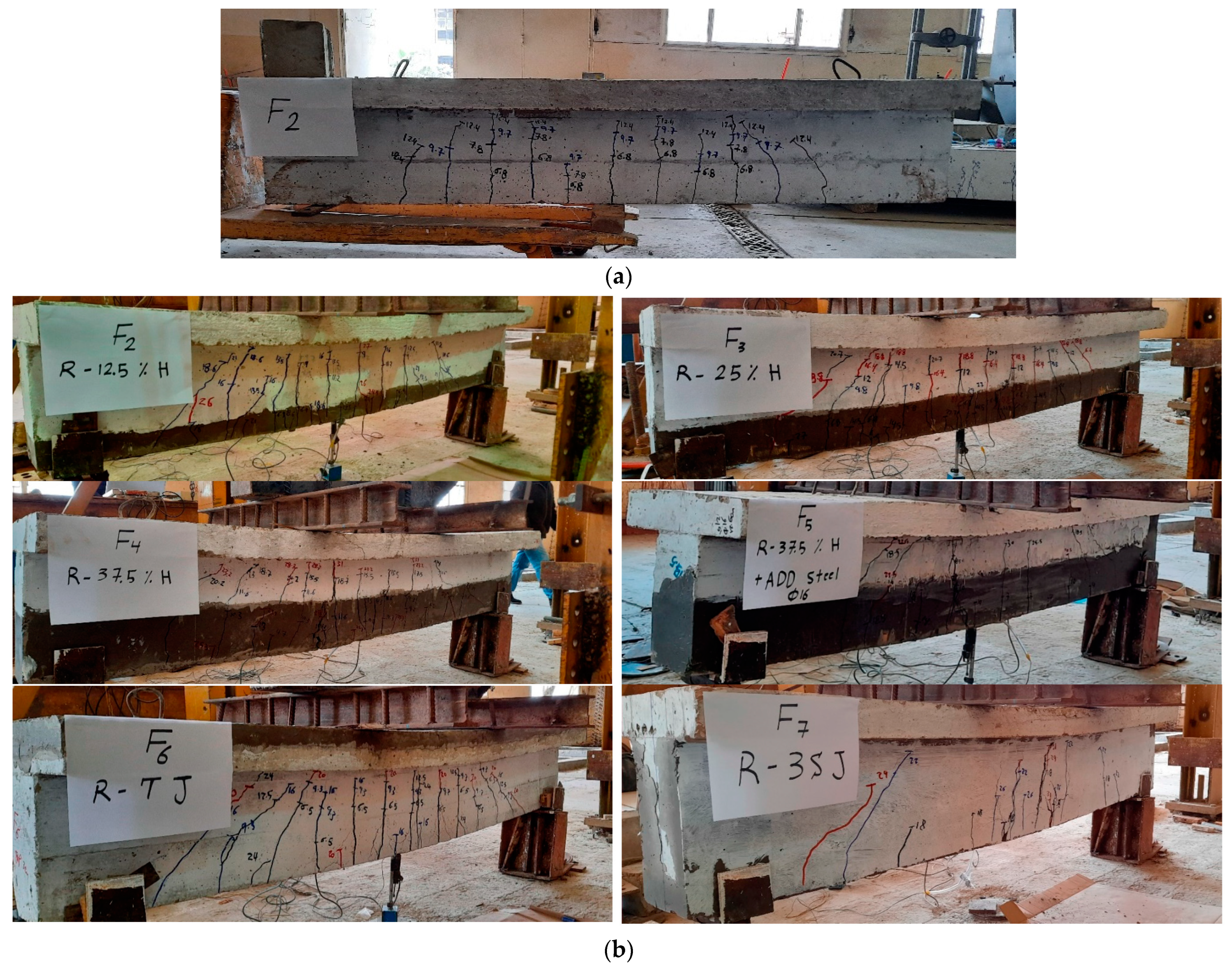
Figure 13.
Load–deflection for all flexural repair techniques.
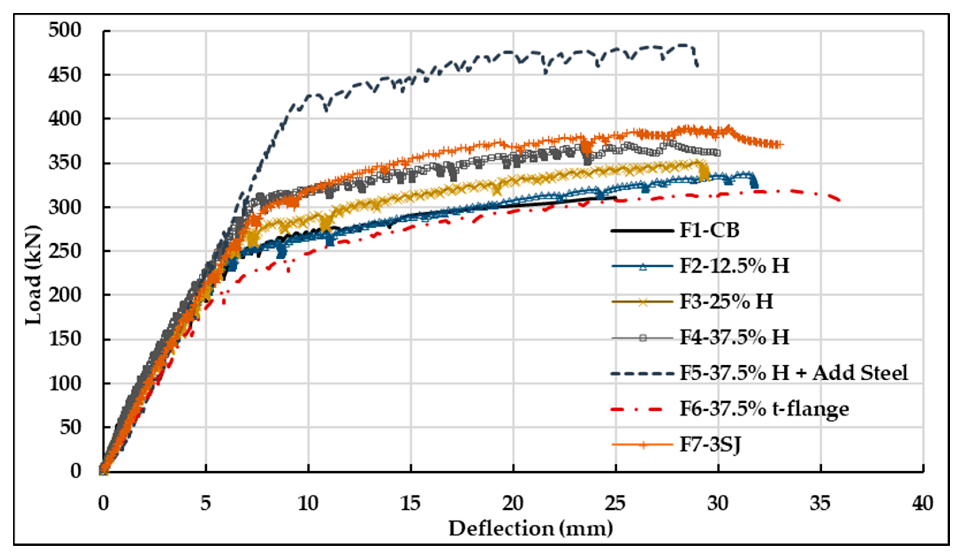
Figure 14.
Comparison of stiffness for all repair techniques.
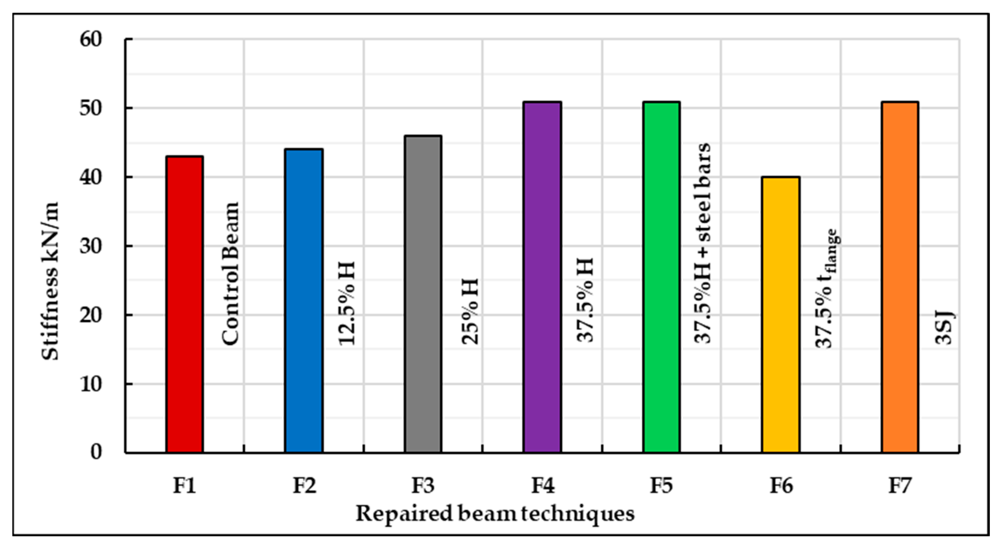
Figure 15.
Ductility index for all repair techniques.
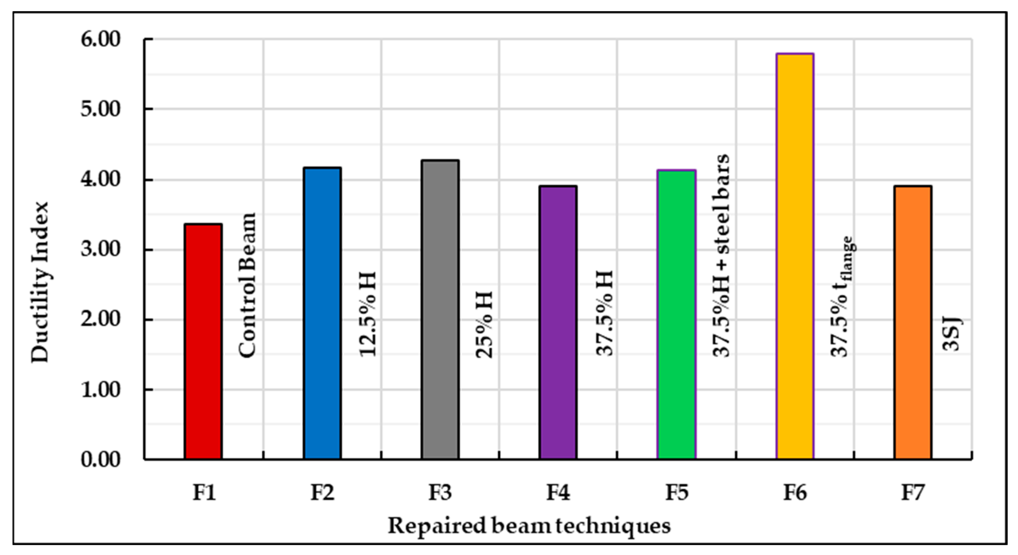
Figure 16.
Crack width for all repair techniques at yield and peak.
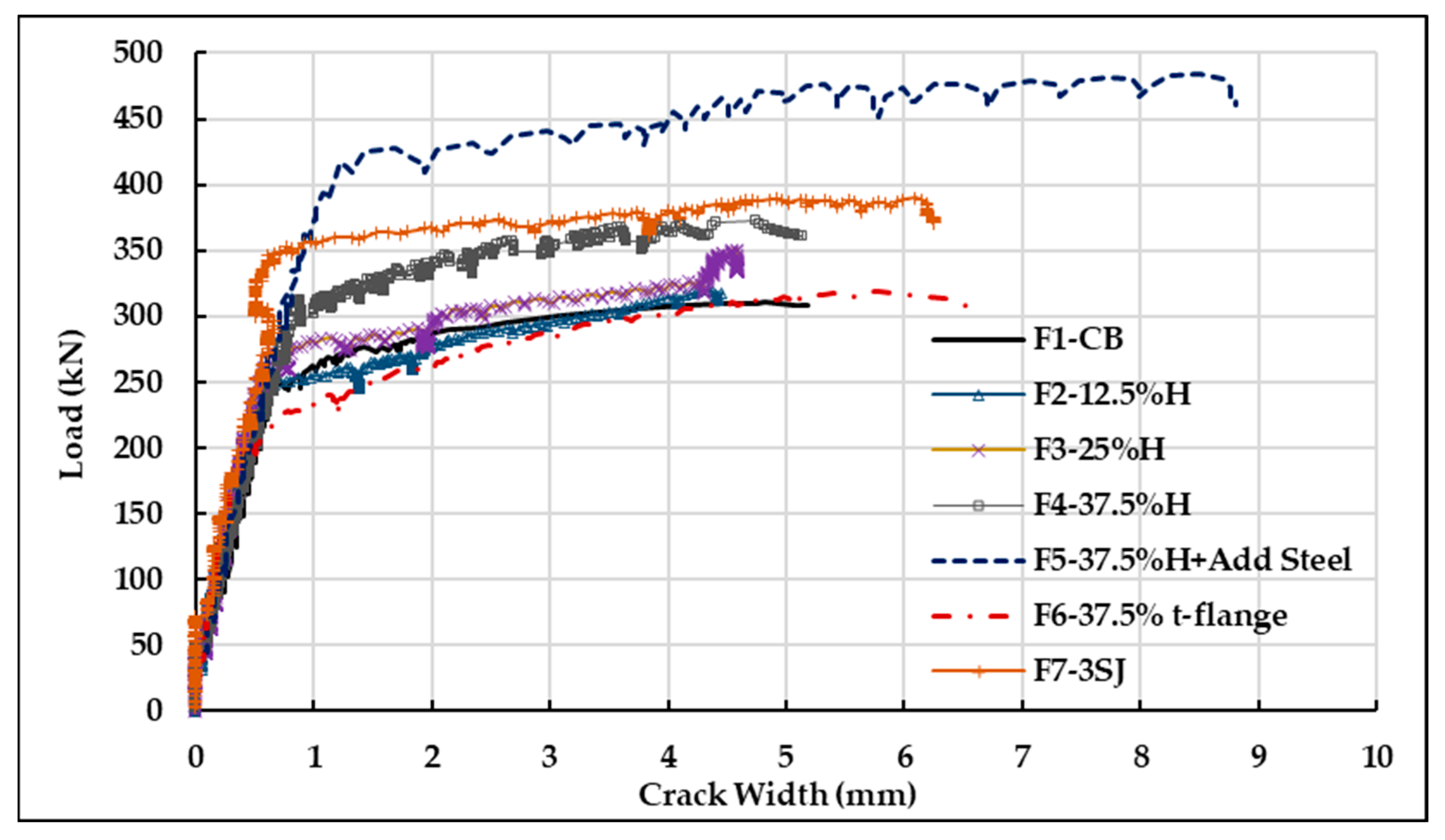
Figure 17.
Strains measured in longitudinal reinforcement for all repair techniques.
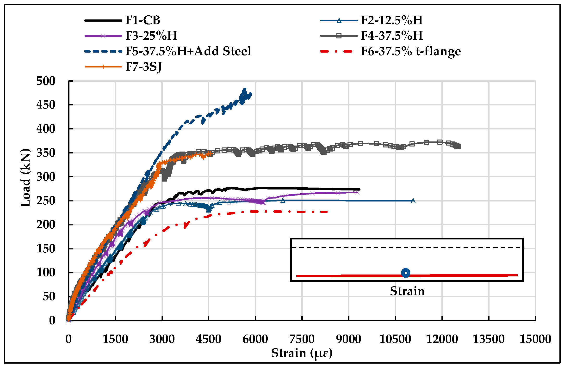
Figure 18.
Load-slippage values for the repaired T-beams.
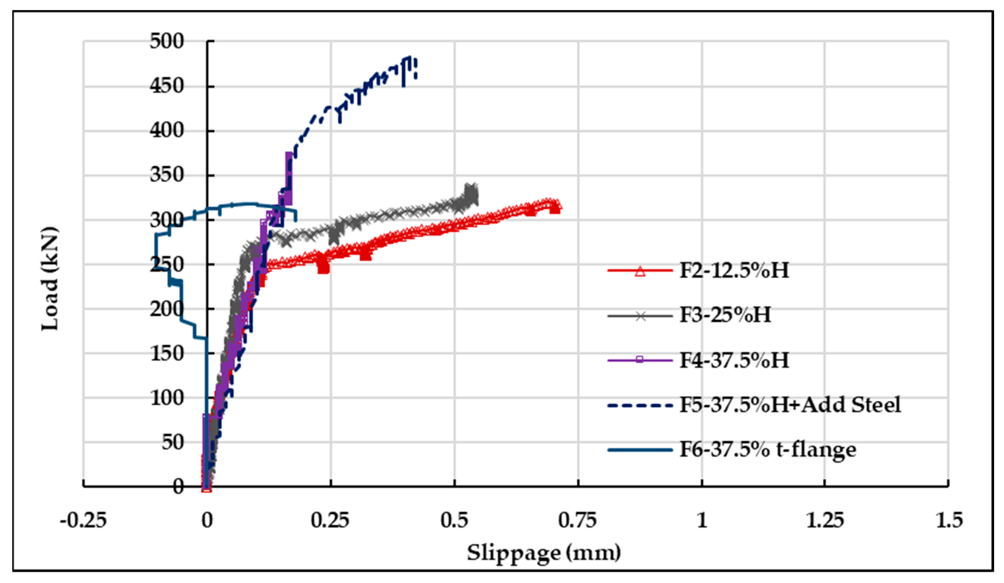
Figure 19.
Section dimension and stress diagram for beams F2, F3, F4, and F5.
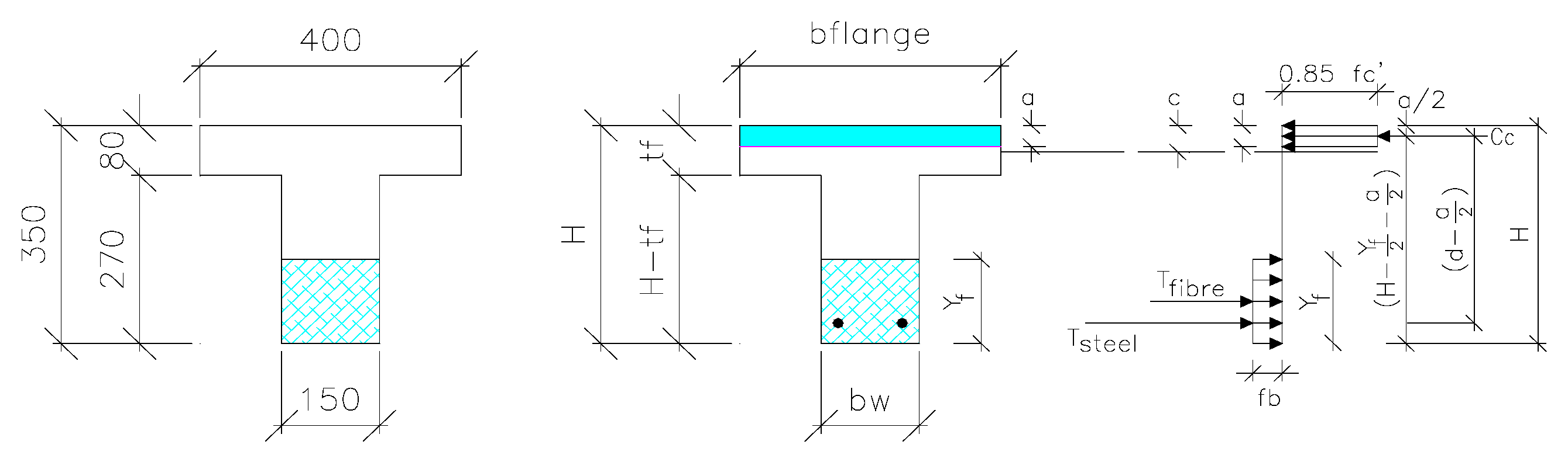
Figure 20.
Idealised tensile stress contribution.

Figure 21.
Section dimension and idealised stress diagram for beam F6.

Figure 22.
Section dimension and idealised stress diagram for beam F7.


Table 1.
Chemical components of FA, GGBS, USF and cement, as determined by XRF (weight %).
| Chemical Composition % | Symbol | FA | GGBS | USF | Cement |
|---|---|---|---|---|---|
| Silica (Silicon Dioxide) | SiO2 | 68.46 | 35.40 | 92.30 | 21.7 |
| Alumina (Aluminum Oxide) | Al2O3 | 11.20 | 17.40 | 0.37 | 6.3 |
| Calcium Oxide | CaO | 6.43 | 36.87 | 0.45 | 64.5 |
| Magnesium Oxide | MgO | 1.38 | 6.83 | 0.46 | 1.86 |
| Ferric Oxide | Fe2O3 | 8.52 | 1.40 | 2.57 | 3.4 |
| Manganese Oxide | MnO | 0.14 | 0.35 | 0.15 | 0.02 |
| Sodium Oxide | Na2O | 0.31 | 0.45 | 0.79 | 0.28 |
| Potassium Oxide | K2O | 0.54 | 0.97 | 0.56 | 0.54 |
| Loss on Ignition | LOI | 1.10 | <0.01 | 1.88 | 2.61 |
Table 2.
SFRGPC mixture composition.
| Material | Mixture Composition kg/m3 |
|---|---|
| Fly ash (FA) | 387 |
| GGBS (Slag) | 310 |
| Undensified silica fume (USF) | 78 |
| Silica sand | 1052 |
| Alkaline activator/binder | 0.50 |
| Potassium silicate/potassium hydroxide | 2.50 |
| Molarity of potassium hydroxide | 16M |
| Alkaline activator solution | 277 K2SiO3 |
| 110 KOH | |
| Steel fibres volume (2%) | 157 |
Table 3.
Summary of repaired T-beams for flexural beams.
| Beam No. | Beam Identification | Repair Pattern | Repair Technique Details |
|---|---|---|---|
| F1 | C.B | - | Control beam |
| F2 | 12.5%H | 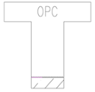 | Replacing at the tension side by 44 mm |
| F3 | 25%H |  | Replacing at the tension side by 87.5 mm |
| F4 | 37.5%H | 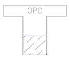 | Replacing at the tension side by 131.25 mm |
| F5 | 37.5%H+ 50%As | Replacing at the tension side by 131.25 mm with additional steel bars * | |
| F6 | 37.5% tflange |  | Replacing at the compression side by 30 mm |
| F7 | 3SJ |  | The web jacket thickness was 25 mm (1/6 width) for each side, and the bottom jacket thickness was 44 mm (12.5%H) |
* Steel bar with a diameter of 16 mm, a yield strength 471 MPa, and an ultimate strength of 583 MPa.
Table 4.
Summary of test results of control T-beam and repaired beams for flexural.
| Beam No. | Preload Damage Level | Repair | First Crack | Peak Load | Prepair–Pcontrol | Failure Mode (S-F) * | |||
|---|---|---|---|---|---|---|---|---|---|
| Pcr kN | Δcr mm | Ppeak kN | Wc mm | Δp mm | |||||
| F1-CB | Ppeak | No | 40.17 | 0.6 | 310 | 5.1 | 25 | - | F |
| F2-12.5%H | 50% Ppeak | yes | 31.6 | 0.58 | 337 | 5.68 | 31.23 | 8.7% | F |
| F3-25%H | 50% Ppeak | yes | 44.38 | 0.87 | 350 | 4.6 | 29.08 | 12.9% | F |
| F4-37.5%H | 50% Ppeak | yes | 48.4 | 0.9 | 372.3 | 4.75 | 27.7 | 20.1% | F |
| F5-37.5%H+ 50%As | 50% Ppeak | yes | 44.83 | 1.25 | 483.7 | 8.5 | 28.5 | 56% | F |
| F6-37.5% tflange | 50% Ppeak | yes | 24.68 | 0.62 | 318.4 | 5.7 | 33.1 | 2.7% | F |
| F7-3SJ | 50% Ppeak | yes | 72.5 | 1.64 | 390 | 6.1 | 30.5 | 25.8% | F |
* S: shear failure–F: flexural failure.
Table 5.
A mechanical model results of repaired T-beams for flexural.
| Beam No. | Preload Damage Level | Repair | Experimental | Predicted | Experiment–Predicted | ||
|---|---|---|---|---|---|---|---|
| Pexp kN | Mexp kN.m | PPre kN | MPre kN.m | ||||
| F1-CB | Ppeak | No | 310 | 93 | 318 | 95.5 | 0.975 |
| F2-12.5%H | 50% Ppeak | yes | 337 | 101.1 | 346 | 103.7 | 0.974 |
| F3-25%H | 50% Ppeak | yes | 350 | 105 | 363 | 109 | 0.965 |
| F4-37.5%H | 50% Ppeak | yes | 372.3 | 111.69 | 378 | 113.4 | 0.985 |
| F5-37.5%H+ 50%As | 50% Ppeak | yes | 483.7 | 145.11 | 486.5 | 146 | 0.994 |
| F6-37.5% tflange | 50% Ppeak | yes | 318.4 | 95.52 | 331 | 99.5 | 0.962 |
| F7-3SJ | 50% Ppeak | yes | 389.7 | 116.91 | 392 | 117.7 | 0.994 |
Disclaimer/Publisher’s Note: The statements, opinions and data contained in all publications are solely those of the individual author(s) and contributor(s) and not of MDPI and/or the editor(s). MDPI and/or the editor(s) disclaim responsibility for any injury to people or property resulting from any ideas, methods, instructions or products referred to in the content. |
© 2023 by the authors. Licensee MDPI, Basel, Switzerland. This article is an open access article distributed under the terms and conditions of the Creative Commons Attribution (CC BY) license (https://creativecommons.org/licenses/by/4.0/).
Share and Cite
MDPI and ACS Style
Khalifa, A.; El-Thakeb, A.E.-W.; El-Sebai, A.; Elmannaey, A. Innovative Flexural Repair Technique of Pre-Damaged T-Beams Using Eco-Friendly Steel-Fibre-Reinforced Geopolymer Concrete. Fibers 2024, 12, 3. https://doi.org/10.3390/fib12010003
AMA Style
Khalifa A, El-Thakeb AE-W, El-Sebai A, Elmannaey A. Innovative Flexural Repair Technique of Pre-Damaged T-Beams Using Eco-Friendly Steel-Fibre-Reinforced Geopolymer Concrete. Fibers. 2024; 12(1):3. https://doi.org/10.3390/fib12010003
Chicago/Turabian StyleKhalifa, Ashraf, Abo El-Wafa El-Thakeb, Ahmed El-Sebai, and Ahmed Elmannaey. 2024. "Innovative Flexural Repair Technique of Pre-Damaged T-Beams Using Eco-Friendly Steel-Fibre-Reinforced Geopolymer Concrete" Fibers 12, no. 1: 3. https://doi.org/10.3390/fib12010003
Note that from the first issue of 2016, this journal uses article numbers instead of page numbers. See further details here.