
Mechanical Performance of Cementitious Materials Reinforced with Polyethylene Fibers and Carbon Nanotubes

1
Department of Civil Engineering, College of Engineering, The American University of Sharjah, Sharjah P.O. Box 26666, United Arab Emirates
2
Engineering Systems Management, Department of Industrial Engineering, American University of Sharjah, Sharjah P.O. Box 26666, United Arab Emirates
3
Department of Civil, Environmental and Architectural Engineering, University of Kansas, Lawrence, KS 66045, USA
*
Author to whom correspondence should be addressed.
Fibers 2024, 12(1), 1; https://doi.org/10.3390/fib12010001
Submission received: 14 September 2023
/
Revised: 1 December 2023
/
Accepted: 6 December 2023
/
Published: 20 December 2023
(This article belongs to the Special Issue The Use of Fibers in the Field of Structural and Earthquake Engineering: Experimental Measurements and Numerical Simulations)
Abstract
:The cracking of cementitious materials due to their quasi-brittle behavior is a major concern leading to a loss in strength and durability. To limit crack growth, researchers have incorporated microfibers in concrete mixes. The objective of this study is to determine if nano-reinforcements can arrest cracks and enhance the material performance in comparison to microfibers. A total of 28 specimens were prepared to investigate and compare the effects of incorporating carbon nanotubes (CNTs) as a nano-reinforcement and polyethylene (PE) fibers at a macro-level and their combination. Compressive and flexural strengths were experimentally tested to assess the mechanical performance. The microstructure of the mortar samples was also examined using a scanning electron microscope (SEM) and energy-dispersive X-ray spectroscopy (EDX). The ductility increased by almost 50% upon the addition of CNTs, while no significant enhancement was witnessed for the compressive strength. The flexural strength increased by 169% and the flexural strain by 389% through the addition of the combination of CNTs and PE fibers.
1. Introduction
Carbon nanotubes (CNTs) have extraordinary mechanical properties. Compared to steel, these tiny particles’ ductility is 60 times higher, their tensile strength is 100 times higher, and their modulus of elasticity is five times larger [1]. When incorporated into the concrete mixture, it creates a layer (measuring 1 to 5 µm in thickness) that covers the cement and filler particles, making them more tightly interlocked and thus preventing the formation and propagation of cracks at the microscale [1]. Without CNT reinforcement, the presence of calcium hydro-silicate crystals at the interface between the cement particles and aggregates weakens the overall structure [2]. Ferro et al. [3] indicated that the addition of 0.5% weight of multiwall carbon nanotubes (MWCNTs) to the mortar as reinforcement caused an approximately 50% increase in the dissipated energy density, at any point during the curing process. This increased the internal damage before failure. CNTs impede the formation and spread of cracks at the nanoscale, rather than just at the microscale. Adhikary et al. [4] examined the influence of different methods for producing CNTs on mechanical and microstructural properties. The authors’ conclusion was that CNTs integrated with cement-based composites exhibit a superior mechanical performance owing to an enhanced crack bridging and adhesion to concrete. The microstructure of the composite exhibited an increased production of calcium silicate hydrate (CSH) gel, which enhances the mechanical strength of the concrete. Additionally, the results demonstrated excellent compatibility between cementitious materials and CNTs. Du et al. [5] investigated the durability and mechanical behaviors of a cement-based composite with CNTs. The durability test involved both impermeability and frost resistance. It showed an improvement in the diffusion coefficient of the CNT composite compared to the control sample.
Hunashyal et al. [6] revealed that beam toughness and flexural capacity can be greatly enhanced by addition of 0.25 wt.% (by the mass of cement) of MWCNTs. Similar results were obtained by Cerro-Prada et al. [7], who found that the compressive strength increased by 25% and the flexural strength by 20% upon the addition of 0.02 wt.% MWCNT. Yakovlev et al. [2] focused on producing pre-stressed poles for high-voltage power lines. The authors stated that the flexural strength of cement concrete increased by as much as 46% when reinforced with MWCNTs, indicating a similar pattern of behavior. Ferro et al. [3] examined the flexural capacity of plain mortar versus CNT-reinforced mortar at various curing times, finding that the greatest impact of the CNT reinforcement occurs within the first day of curing. However, given that the standard curing period is typically 28 days, a 30% boost in flexural capacity can be deemed the most significant outcome of the experiment. Mohsen et al. [8] used a permeability test to demonstrate that the inclusion of 0.15 and 0.25 wt.% CNTs in concrete led to a boost of over 100% in the flexural strength compared to CNT-free concrete. Additionally, the use of CNTs resulted in an approximately 150% increase in concrete ductility. Lee et al. [9] used multi-walled carbon nanotubes to study the bond between the composites and a reinforcing bar. They showed that there was a 46.42 MPa increase in the compressive strength when they used 0.5 wt.% of the fibers, whereas when the percentage increased over 1%, the compressive strength test results of the cementitious composites showed that there was an insufficient increase in the compressive strength of the specimen. Ramezani et al. [10] studied the effects of the experimental variables of CNTs on the concrete flexural strength. They showed that a higher CNT aspect ratio (AR) from 400 to 800 and a concentration (κ) of 0.08–0.18 wt.% resulted in the highest improvement in the flexural strength.
Sasmal et al. [11] noted that CNTs will one day help civil engineers to make “crack-free” concrete, but one of the problems associated with the addition of CNTs in cement paste is the lack of proper dispersion. Several studies have been conducted to increase the dispersion and effect of CNTs in concrete mixes by incorporating silica fumes (SFs), also known as microsilica. In a study conducted by Kim et al. [12], the researchers attempted to incorporate CNTs into the concrete mix, with and without SFs. The researchers concluded that incorporating CNTs into the concrete mix without any silica fumes (or any other dispersion techniques) leads to negligible effects of CNTs on the behavior of concrete. On the other hand, adding silica fumes to the mix incorporating CNTs provided significant enhancements to the mechanical performance of concrete. Several techniques, such as the addition of dispersant materials (e.g., superplasticizers [13,14] and surfactants [15,16]) and defoaming agents [17], the use of different mixing techniques (e.g., magnetic stirring [18] and ultrasonication [19]), or the application of experimental design to ascertain the materials’ factors [20], have been employed to optimize and increase the dispersibility of CNTs, with varying results.
Since the 1960s, researchers have found that reinforcing concrete with fibers in discrete form is a considerably effective method. Well-dispersed fibers increase the homogeneity of concrete and unify its overall mechanical properties in all directions and planes. Under loading, as concrete starts to crack, the fibers inside the concrete start to inhibit the crack growth and propagation, leading to the increase in the strength and ductility of concrete [21]. Fibers that can reinforce concrete come in different shapes and can be made from different materials, and thus their properties and effects on concrete do vary. For the application of concrete reinforcement, the most common fibers include steel fibers, glass fibers, natural organic and mineral fibers, polypropylene fibers, Kevlar, nylon, and polyester. Fibers are usually characterized by their “aspect ratio”, which is a measure of the fiber’s length compared to its equivalent diameter (L/D) [21]. According to Wafa [21], it is essential to achieve a high level of dispersion of the fibers in the concrete to observe their effect on improving the mechanical properties of concrete, as fibers naturally tend to aggregate during mixing, especially while adding them to the mix. Common factors that increase the fibers’ tendency to aggregate include a high aspect ratio, high percentages of fibers in the mix, and the dimensions and amounts of the aggregates. Karim and Shafei [22] compared the performance of ultra-high-performance concrete (UHPC) reinforced with synthetic fibers, namely, nylon, polypropylene, polyvinyl alcohol, alkali-resistant glass, and carbon instead of steel. The results revealed that polyvinyl alcohol fibers provided the best workability and, at the same time, exhibited the highest first-crack strength, maximum strength under flexural load, as well as the highest toughness, posing them as potential candidates to replace steel fibers.
Said and Abdul Razak [23] studied the effect of adding polyethylene fibers with different aspect ratios using other engineered cementitious composites (ECCs). The authors highlighted that the compressive strength of FRC was found to be inversely proportional (at a low rate) to the reinforcing index (R.I.) and this, most logically, would be due to the fibers not being well dispersed in the mix. Polyethylene is a hydrocarbon (composed of carbon and hydrogen) with the chemical formula of (C2H4)n, and polyethylene fibers have been widely utilized in recent studies as micro-reinforcement due to their mechanical performance and availability.
Salemi and Behfarnia’s [24] study revealed that adding reinforcement to fiber-reinforced concretes at the nano-level does improve the compressive strength of concrete. By substituting 3% of the cement weight with nano-alumina, the compressive strength of the concrete was increased by 8%. Up to a 30% increase in compressive strength was also witnessed when using 5% nano-silica. This is a positive sign, indicating the compatibility and harmony in functionality between reinforcement at the micro-level and reinforcement at the nano-level within the same concrete mix. Similar to Said and Abdul Razak’s [23] study, in which concrete was reinforced with polyethylene fibers alone, Salemi and Behfarnia [24] also faced the lowered workability of the concrete mix after adding the nano-material. This means that both, the micro- and the nano-, reinforcements of concrete mixes do lower the workability of concrete. Most importantly, it can be concluded, from Salemi and Behfarnia’s [24] study, that adding nano-reinforcement to FRC improves the durability measures of the concrete significantly. It is also worth mentioning that the researchers concluded that the concrete mix that had both fibers and nano-material had the highest frost resistance among the tested specimens that either had fibers alone, nanomaterial alone, or no reinforcement at all. More specifically, according to Salemi and Behfarnia [24], around an 87% increase in durability was obtained by incorporating 5% nano-silica in addition to 0.2% polyethylene fibers in the same mix.
In a similar attempt, Shah et al. [25] studied the effect of reinforcing concrete with both micro- and nano-fibers, which they referred to as “ladder reinforcement”. In this study, the authors reinforced concrete with both carbon nano-fibers (CNFs) and polyvinyl alcohol (PVA) microfibers. Shah et al. [25] applied ultrasonic energy to disperse carbon nano-fibers (CNFs) in a surfactant solution before adding them to the concrete mix to achieve the sufficient dispersion of the CNFs in the mix. The study showed that reinforcing the concrete mix with 0.048% (weight of cement) CNFs yielded improvements in flexural capacity, modulus of elasticity, and toughness by up to 40%, 75%, and 35%, respectively, compared to the plain mix. Similarly, reinforcing plain concrete with PVA microfibers led to improvements in the flexural capacity, modulus of elasticity, and toughness. Shah et al. [25] stated that the flexural capacity and the modulus of elasticity increased by less than 10%, while the toughness increased by 10 times. When the concrete was reinforced with both nano-fibers and PVA microfibers, all the mechanical properties (flexural capacity, modulus of elasticity, and toughness) improved. The improvement, in this case, exceeded those in the other cases, i.e., incorporating CNFs alone or incorporating PVA microfibers alone, individually.
Potapov et al. [26] investigated the impact resistance of concrete reinforced with silicon dioxide nanoparticles and 1.5 wt.% basalt microfiber. The compressive strength of the specimens examined was 1.5 higher than that without nanoparticles and microfibers, the flexural strength was increased by 3.4 times, and the specific energy of impact destruction was 22.2 times higher. This was attributed to the increased volume fraction of the denser CSH gel, due to nanogranules filling its volume and the interfacial transition zone, and the enhanced shear stress of the CSH gel. Recently, multiscale analysis has been used to explain the physical characteristics of cement pastes using CNTs [27,28]. Authors have suggested that numerical analysis can provide guidance for optimizing cement-based composites and therefore reduce the need to carry out extensive and expensive experiments. Kavvadias et al. [29] studied the results obtained experimentally with those predicted by a multiscale computational investigation. The investigators found that the 0.1 wt% MWCNTs/CementPaste composite demonstrated the least number of errors between the numerical model and the experimental measurements.
There have been several attempts to reinforce concrete with fibers in order to inhibit crack growth at the micro-level, and new insights include using nano-materials to reinforce cement-based composites at the nano-level in order to inhibit crack initiation and growth at earlier stages. The main challenge associated with these ideas is dispersing the nano- or micromaterial thoroughly within the cementitious mix. In fact, the poor dispersion of these materials yields almost no considerable effects or even adverse ones, since the fibers act as voids in the concrete under compressive loading [21].
The present study aims to provide a practical solution to efficiently control crack initiation and growth in cementitious materials in order to reduce their quasi-brittle behavior. The main concept is to reinforce concrete at the nano-level, micro-level, and both at the same time. The dispersion challenge is also addressed in this study by applying novel approaches to disperse each of the reinforcing materials in the cementitious mix. Furthermore, this work is oriented towards the mechanical performance of reinforced concrete rather than other performance criteria, such as electrical conductivity and frost resistance, which have already been addressed in the literature. This study aims to enrich and fill a gap in the literature, especially since nano-technology is still poorly employed in civil engineering applications and not enough research has been conducted to understand its potential benefits in the field.
2. Materials and Methods
2.1. Materials
The reinforced mortar samples prepared and tested in this study were composed of Type I Portland cement, silica fumes (to achieve the efficient dispersion of CNTs within the cement matrix), crushed sand, CNTs, and PE fibers.
A normal Type I Portland cement was used as the main binder material. The specific surface area of the cement, based on the Blaine test, was 355 m2·kg−1. Silica fumes were supplied by Elkem AS, Silicon Materials, with a specific gravity of 2.1–2.4, densified bulk density of 608–720 kg/m3, and particle size of 0.4 µm.
Crushed sands, with particle sizes in the range of 0.15–4.75 mm, were used as the fine aggregate in this study, with a fineness modulus of 2.4. The specific gravity was 2.65, and they had a water absorption of 5% (determined in the lab, following [30]).
Industrial-grade MWCNTs, shown in Figure 1b, produced by Nanostructured and Amorphous Material Inc., Katy, TX, USA, were used. CNTs functionalized with carboxyl groups (CNT-COOH) were used in this study to ensure a stronger bond with SFs and, thus, a better dispersion in the mortar mix [31]. Table 1 shows the properties of the CNT-COOH used, and Figure 1a shows a sample of it.
Ultra-high-modulus polyethylene fibers were used as the micro-reinforcement for the mortar (in mixes C and D). The properties of these fibers are illustrated in Table 2. The dimensions of these fibers indicated that they had an aspect ratio of L/D = 0.012/0.000038 ≈ 316. For the fibers to spread out and become easy to add to the mortar mix, they were first placed in a well-sealed metallic cylinder and subjected to high-pressure air for a few seconds, as shown in Figure 2.
As per the ASTM standards, a standard Hobart mixer was used for mixing cementitious composites. Similar to what was performed in [12,31], all dry materials (cement and fine aggregates, silica fumes, polyethylene fibers, and/or CNTs) were first dry-mixed for four minutes. Next, water was gradually added to the mix, and additional five minutes of mixing were allowed. The fresh mix was poured into three layers in the molds, and sufficient compaction was applied to each layer. The mortar was de-molded after 24 h and was placed in a water basin for curing.
2.2. Experimental Program
No standards or guidelines have yet been established for the mix design of CNT-reinforced mortar. For that reason, the mix design in this study was conducted based on information collected from credible, recently published sources in the literature, combined with a few trials (“pilot” tests) in the lab before the actual commencement of this research and the standard procedure for the design of high-performance mortar.
As mentioned earlier, the major challenge in reinforcing concrete with CNTs is dispersing these nano-materials within the matrix of the cement paste, where they would naturally tend to group and form agglomerates. In this study, microsilica (also known as silica fumes) was used for the mechanical dispersion method. Based on the findings from [31], the percentage of silica fumes in all mixes was kept at 15% (weight of cement), since this percentage was found to be the most efficient amount of silica fumes to be used to dispersed CNTs well in concrete without significantly compromising the workability.
Four mix designs were prepared, as shown in Table 3. Mix A was the control mix. It did not include any CNTs or PE fibers. Mix B had CNTs in it (0.15% weight of cement). Mix C had PE fibers in it (2% volume of the batch). Mix D included both CNTs (0.15% weight of cement) and PE fibers (2% volume of the batch) in it. The water-to-binder ratio was initially kept at 0.3 (as in [31]). However, based on the laboratory trial mixes (as previously explained in Section 2.2.), it was found that a water-to-binder ratio of 0.4 is the most efficient ratio to ensure enough workability. Thus, a water-to-binder ratio of 0.4 was considered in the mix design, noting that the binder amount included both cement and silica fumes. Having such a low value of water-to-binder ratio increases the collision between the particles of microsilica and CNTs in the mix, and thus enhances dispersion [12]. The cement to sand ratio was kept at 1.3 (as in [23]). Wherever CNTs were incorporated, they were added in the amount of 0.15% of cement weight. This percentage was tested and proved to be sufficient by Tamimi et al. [31], and having CNTs in larger percentages can significantly reduce the workability of the mix [12]. Wherever PE fibers were incorporated, they were added in the amount of 2% by volume to the mix. Based on the study conducted by [23], exceeding beyond 2% volume of fiber (Vfiber) does not cause considerable effects on the flexural capacity of concrete slabs but reduces the workability of the mix. Thus, 2% Vfiber was taken as the optimum value. The water absorption of the aggregates was tested as per [32], and the amount of water was adjusted to be 5% depending on the water absorption capacity of the aggregates.
A total of 28 specimens were tested in this study. The conducted tests were compression test, flexural test, and rapid chloride permeability test. From each of the four mortar mixes listed in Table 3, 7 specimens were prepared: 3 cylinders (for the compression test), 1 cylinder (for the rapid chloride permeability test), and 3 beams/prisms (for the flexural test). The specimens were prepared by casting mortar mixes in the metallic mold, as seen in Figure 3. Figure 3a,b show the molds for the 100 mm diameter × 200 mm cylinder and the 200 × 50 × 50 mm beams, respectively.
2.3. Material Characterization Tests
Slump (Figure 4a) and air content (Figure 4b) tests, as per ASTM C143/C143M and ASTM C231/C231M, respectively, in addition to wet density and temperature (90 min after casting) tests were performed on the fresh mortar samples to assess their properties.
After 28 days of curing in the lab, the specimens from each mix were tested, as listed above. Compressive and flexural tests were conducted on each sample, and the average of the three samples was taken as the final strength value for each of the four mixes. Both sets of testing were carried out using an Instron Universal Testing Machine, as shown in Figure 5. Compression testing was conducted according to ASTM C39. The cylindrical specimens were first prepared for the compression test by attaching external strain gauges (Figure 6a) in order to record the strain using the same time increments as the load (which was then used to calculate the compressive stress by diving the recorded incremental loads by the cylinder’s cross-sectional area). Flexural testing was conducted in a 3-point-bending setup as per ASTM C78. Similarly, prism specimens were first prepared by attaching external strain gauges (Figure 6b) in order to record the strain using the same time increments as the load. The flexural stress of each prism was eventually calculated as the modulus of rupture: fb (where F is the total load on the prism, L is the clear span of the prism, b is the width of the prism, and d is the depth/height of the prism). With the stress and the strain values both determined at the same time increments, the stress–strain curves from the compression and flexural tests were eventually plotted.
A rapid chloride permeability test (RCPT) was conducted according to ASTM C1202-97 on three samples from each mix at the age of 28 days. A 50 mm slice of mortar was prepared and placed in direct contact with a sodium chloride solution on one face and with sodium hydroxide on the other face for six continuous hours. A 60 V potential difference was applied to the specimen during the test period, and the total charge passing through the specimen was recorded and used as an indication of the mortar’s permeability, assuming that this charge passed through the mortar after chloride ions diffused into it and increased its conductivity considerably.
To better understand the surface morphology of the produced mortar, the remains from the mortar cylinders that underwent compressive testing were collected and analyzed using a scanning electron microscope (SEM) and with energy-dispersive X-ray spectroscopy (EDX) imaging. The SEM image results from the interaction of a focused beam of electrons directed towards the mortar sample (Figure 4c). It reflects the morphology of the surface of the mortar and its microstructure.
3. Results and Discussion
The experimental results of the tests conducted in this study are presented, analyzed, and synthesized in this section.
3.1. Properties of the Fresh Mortar
The slump, air content, density, and temperature (90 min after casting) were measured for the four different mixes. The results of these properties of fresh mortar are summarized in Table 4. The results show that the addition of CNTs to the control mix did not have a substantial effect on any of the measured properties of the fresh mortar. Comparing Mix B (which incorporated CNTs) and Mix A (the control plain mix), the slump increased by 5%, the air content increased by 4.3%, the wet density increased by less than 0.2%, and the temperature increased by around 2%. On the other hand, the addition of polyethylene fibers to the mortar caused a significant decrease in the workability. The slump of Mix C (which incorporated fibers) was 3 cm, while the slump of Mix A (the control plain mix) was measured and recorded as 6 cm. This means a 50% reduction in the workability of the mortar. The air content also increased, with a 3.2% air content in Mix C compared to 2.3% in the control mix. Similarly, the temperature was neither substantially affected by the addition of PE fibers alone (Mix C) nor by the addition of both PE fibers and CNTs (Mix D). According to Vairagade and Kene [33], the slump measurements for the four mixes indicate that Mixes A and B have a “medium” workability, whereas Mixes C and D have a “low” workability. These results are rational and are justified by the fact that PE fibers, because of their high surface areas, do absorb significant amounts of water from the cement paste and are covered by it, which causes the workability of the whole mix to decrease [33]. Due to this effect of PE fibers making some parts of mortar denser, the wet density of Mix C increased in comparison to that of the control mix (around a 9% increase).
The consistency of the slump values in Mixes C and D (3 cm to 3.6 cm) is worth noting. It indicates that the PE fibers in both mixes are well-dispersed, and this is the main factor for efficiently utilizing synthetic PE fibers as reinforcement to mortar [33]. The small increase in the slump in Mix D compared to Mix C is clearly due to the addition of CNTs to the mix, which has a similar effect on Mix B (when compared to Mix A).
3.2. Compressive Test (Cylinders)
Figure 7 illustrates the stress–strain results of the three cylinders tested from each mix under static loading. The average maximum value of the compressive strength of Mix A (51, 46, and 49 MPa) was 48.7 MPa. For Mix B, the average compressive strength of the three specimens (44.5, 45, and 46 MPa) was 45.2 MPa (with a maximum difference of 3.4%). The average maximum value of the compressive strength of Mix C (51, 47.4, and 49 MPa) was 49.20 MPa (with a maximum difference of 7.6%). For Mix D, the average maximum value of the compressive strength (51, 48.4, and 49 MPa) was 49.5 MPa (with a maximum difference of 5.30%). The standard deviations associated with the aforementioned results are 2.05 (for Mix A), 0.62 (for Mix B), 1.47 (for Mix C), and 1.11 (for Mix D), indicating an acceptable precision in all cases.
The results reveal that Mix D (which incorporated both CNTs and PE fibers) had the highest compressive strength, while Mix B (which incorporated CNTs alone) achieved the lowest compressive strength. Table 5 summarizes the average compressive strength, the modulus of elasticity (determined as the initial tangent modulus as per [34]) and the ductility (considering the yield strain at the point where the linear portion of the stress vs. strain curve starts to terminate, as per [35]) for each mix type.
As seen from the results, while there was a very slight increase (around 1%) in the compressive strength of Mixes C and D compared to the control mix, Mix B had a compressive strength that was around 7% lower than that of the control. The decrease in compressive strength after adding CNTs to the plain mortar, despite being small in magnitude, was unexpected. With 15% weight of cement silica fumes and 0.15% weight of cement CNTs, Kim et al. [12] witnessed around a 20% increase in the compressive strength. According to the researchers of [12], the only sample in which adding CNTs caused a lower compressive strength was in which CNTs were added in amounts exceeding 0.15% weight of cement. This could be attributed to the CNT dispersion, which could have caused the CNTs to agglomerate in groups, and thus, mortar specimens with CNTs were slightly weaker in carrying compressive loads. The four mixes included in this study had almost the same compressive strength (around 48 MPa on average). A similar behavior was also exhibited in terms of the compression modulus of elasticity (E). Mixes B, C, and D had moduli of elasticity lower than that of the control mix (Mix A), and Mix D (which incorporated CNTs and PE fibers) had the lowest modulus of elasticity (17.22 MPa), being 30% lower than that of the control. The ductility was calculated by finding the ratio of the maximum strain achieved at the failure point to the strain at the yield point (after which the strain starts to become plastic/permanent) [36]. While the compressive strength was not affected to a considerable extent by either type of reinforcement (CNTs or PE fibers), the compressive ductility was significantly enhanced by both. Referring to Table 5, Mix B (which incorporated CNTs alone) had a compressive ductility of 2.383, providing more than 50% enhancement to the control mix. The PE fibers alone did enhance the compressive ductility of the plain mortar by 34%, with a compressive ductility of 2.122. The combined effect of both CNTs and PE fibers was around 20% enhancement in comparison to the control mix, with a value of 1.903 for the compressive ductility of Mix D.
3.3. Flexural Tests (Prisms)
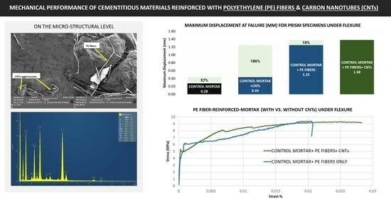
Figure 8 shows the flexural stress–strain curve of the specimens for each mix. The average flexural strength values of the three specimens from Mix A (3.10, 2.97, and 2.55 MPa), Mix B (4.8, 4.76, and 4.70 MPa), Mix C (9.37, 8.31, and 7.61 MPa), and Mix D (9.20, 7.80, and 6.20 MPa) were 2.87, 4.75, 8.43, and 7.73 MPa, respectively. The standard deviations associated with the aforementioned results were 0.23 (for Mix A), 0.04 (for Mix B), 0.72 (for Mix C), and 1.23 (for Mix D), indicating closely grouped/precise values. As seen in Figure 8, depending on the mix, the damage behavior exhibited by the specimen is different, leading to various trends up to failure. The specimens with polyethylene fibers exhibited a sharp increase in stress followed by a strain hardening effect in addition to an increase in the ductility, as seen in Figure 8c,d, while adding CNTs enhanced the ductility and increased the modulus of the mortar specimens, as seen in Figure 8b. The combined effect of strain hardening and enhanced ductility in addition to the increase in the flexural strength was clear in Mix D with both polyethylene fibers and CNTs.
Table 6 summarizes the average flexural strength and the maximum deflections of the mortar specimens at failure for each mix type, respectively. The results show that Mix C (which incorporated PE fibers alone) had the highest value (8.43 MPa) compared to the other three mixes and was better the control mix by more than 193%. CNTs alone also enhanced the flexural strength of the plain mortar by around 65%, with a flexural strength of 4.75 MPa. The combined effect of both CNTs and PE fibers enhanced the flexural strength of the plain mortar by around 169%, with a flexural strength of 7.73 MPa. Mix A (control mix) had the lowest flexural strength (2.87 MPa) and exhibited a very brittle behavior in the testing machine. Hunashyal et al. [6] reported similar results in their study, in which plain mortar mixes were reinforced with CNTs alone. According to their results, compared to beams cast from cement alone, CNT-reinforced cement beams (with 0.25% weight of cement MWCNTs) had a flexural capacity that was, on average, 47% higher. This study indicated that even the addition of CNTs with percentages as low as 0.025% weight of cement to the mortar mix could have remarkable effects on the overall flexural performance of the reinforced beams. Similarly, in an experimental study reported by Ferro et al. [3], prisms (40 × 40 × 160 mm) of cementitious mixes (mortars) reinforced with 0.5% weight of cement of MWCNTs, as well as without any CNTs, were tested for flexural strength. The CNT-reinforced specimens showed flexural capacities that were significantly enhanced. For 1, 7, and 28 days of curing, the % difference were 53%, 13%, and 30%, respectively. As discussed previously, the maximum displacement at failure is another property that was significantly enhanced after adding CNTs and/or PE fibers to the plain mortar. Table 6 shows that the average maximum deflection recorded for Mix A was as low as 0.277 mm. Adding CNTs increased this value by 57.3% to reach 0.4359 mm. Adding PE fibers had a much larger effect than that of CNTs in this regard; it increased the maximum deflection to 1.2486 mm (a 350% increase in comparison to the control mix). Combining both CNTs and PE fibers increased the maximum deflection of the control mix by 397%, reaching 1.3784 mm at failure.
3.4. Rapid Chloride Permeability Test (RCPT)
The results of the RCPT (average of three samples) of the four mortar mixes included in this study at the age of 28 days are presented in Figure 9 in a bar chart format for easier comparison. The RCPT measures the mortar’s permeability based on the total chloride ion charge that passed through the specimen after being subjected to 60 V for six hours, facing sodium chloride solution on one side and sodium hydroxide solution on the other side [37]. Based on the recorded values of the total charge passed, the RCPT apparatus indicated the categories of the mortar as having low, moderate, or high permeability. The results indicate that the control mix (Mix A) had a low permeability to chloride ions, as the total charge that passed through the specimen of Mix A was 911 Coulombs. Adding CNTs caused a significant increase of 164% in the total charge that passed through the mix (from 911 to 2403 coulombs). Adding polyethylene fibers to the mix had a similar, yet lower, effect on the porosity to chloride ions, with an increase of 57% in the total charge passed (from 911 to 1426 Coulombs). Combining both types of reinforcement, CNTs and PE fibers (the main focus of this study), had the largest effect on the total charge that passed through mortar (Mix D), as it caused an increase of 211%, with a total recorded charge of 2838 Coulombs.
These results directly indicate that adding CNTs to the mortar mix makes it more susceptible to chloride diffusion through its matrix and decreases its durability. In the same vein, some of the previously conducted studies in the literature highly recommend adding nano-materials to the mortar mix to increase its durability in terms of chloride diffusion. For example, Singh et al. [38] reported a 43% increase in chloride ion resistance owing to the addition of 3% silica nano-particles to the mortar mix. These conflicting data can be justified by investigating other perspectives. According to Chang and Song [39], adding CNTs to mortar increases its electric conductivity significantly, since CNTs are electrically conductive by nature. Chang and Song [39] investigated CNT-reinforced mortar as a considerably promising electric deicing system to be implemented in parts of the world where ice and snow need to be removed off the roads very often in order to not disrupt transportation systems. This is because CNT-reinforced mortar heats up very quickly and at low voltages, compared with plain mortar. The major concern when using the RCPT to measure the mortar’s permeability to chloride ions is the rise in the temperature of the mortar specimen being tested, after being subjected to a high voltage (60 V) for six continuous hours. This concern arises specifically for mortar containing highly conductive materials (just like the case of the CNTs in this study). The problem is that the rise in the temperature of the mortar increases its electric conductivity tremendously, and thus increases the total charge that passes through the specimen in the RCPT, which in this case does not necessarily indicate a low resistance to chloride diffusion into the mortar’s matrix [37]. Due to this, the RCPT most probably fails to be an accurate test to measure the permeability of the chloride ions of the mortar containing CNTs in this study (Mixes B and D). If appropriate testing is conducted, CNTs are expected to lower the penetration of chloride ions into the mortar medium as they are nano-materials that increase the homogeneity of the mortar.
3.5. Morphology Analysis (SEM and EDX Tests)
Since mortar is reinforced at the nano- and the micro-levels, analyzing the morphology of mortar specimens adds significant value to this research. SEM and EDX were conducted on the remains from each mix type. Both backscattered (BSE) and secondary electron (SE) modes of the SEM test were used with the proper magnification factors.
Mix A. Figure 10 illustrates the SEM images taken for the control mix (Mix A). Figure 10a was taken in the BSE mode, whereas Figure 10b was taken in the SE mode. As indicated with the arrows and labels, Figure 10a shows a clear microcrack in the control mortar mix. Having similar microcracks in different parts of the morphology of this mix is most likely the main reason that it demonstrated relatively weak mechanical properties (in compression and tension). Similarly, Figure 10b shows a similar void within the morphology.
Figure 10b also shows the formation of the C-S-H gel in most of the captured areas. This indicates that the hydration process of the cement in the mortar mix was mainly completed in 28 days. The C-S-H gel is the main product of cement hydration and is the major component responsible for binding the mortar particles together. The areas identified as the C-S-H gel in Figure 10b were confirmed using the corresponding EDX spectra in Figure 8. Spectra 1 and 2 (Figure 11) indicate a calcium silicon ratio of 2.30 and 2.01, respectively. These values are within the range from 0.7 to 2.1, which is the typical Ca–Si ratio in C-S-H gel [23].
Mix B. Figure 12 illustrates the SEM images taken for Mix B. Figure 12a was taken in the BSE mode, while Figure 12b–d were taken in the SE mode. As indicated with the arrows and labels, some of the CNT agglomerates are visible at such a magnified scale. Mix B had fewer cracks, and when present, they were smaller in size and width than those observed in the control mix. This could explain the relatively high flexural strength that Mix B exhibited in comparison to Mix A. The agglomerates shown in Figure 12c,d are also likely to be the result of CNTs and silica fume particles bonding together within the C-S-H gel due to their different electronic charges, as discussed earlier.
According to Duxson et al. [40], the ratio of silicon to aluminum (Si/Al) in the C-S-H gel normally indicates a higher homogeneity. In the three spectra taken using EDX for Mix B, the Si/Al was considered high. The spectra 1 and 2 shown in Figure 13 indicate Ca/Si ratios of 2.77 and 2.00, most likely indicating the presence of C-S-H gel [41]. The Si/Al ratio of spectrum 2 is relatively very high (14.00 compared to 5.77 in spectrum 1). This, combined with a high percentage of carbon in spectrum 2, most likely indicates the presence of CNTs at this portion in the specimen from Mix B. Similarly, this explains and confirms the enhanced flexural properties demonstrated by Mix B when compared to the control mix.
Mix C. Mix C incorporated PE fibers only (no CNTs). Figure 14 shows the SEM images taken for this mix type. Figure 14a,b were taken in the SE mode, whereas Figure 14c was taken in the BSE mode. PE fibers are clear in Figure 14a,c; they can also be seen bridging the microcracks labeled in the figures.
Examining the EDX spectra for Mix C (Figure 15), spectra 2 and 3 indicate Na/Al ratios of 9 and 6, respectively, which are very high compared to 1.22 in spectrum 1. According to Khan et al. [42], the sodium content in the C-S-H gel is a very strong indicator of the strength of materials. Khan et al.’s study [42] concluded that the compressive strength of mortar increases as the Na/Al ratio increases, which conforms to the results obtained in this study, as Mix C had an even higher impact on the strength of the control mix than Mix B, which incorporated CNTs only.
Mix D. Mix D was the main research object of this study, which aimed to investigate the combined effect of CNTs and PE fibers as reinforcements in mortar. Figure 16 shows the SEM images obtained for this novel mix. As indicated in the figures, PE fibers, as well as CNT agglomerates, can be noted in the morphology of the mortar. It is very evident in this mix that there are few cracks and voids compared to the other three mixes analyzed in this study, especially Mix A (control). This conclusion is based on the SEM images as well as the EDX spectra.
It is worth noting that the lower number of cracks and voids were well reflected on the mix’s flexural behavior rather than its compressive one, as demonstrated earlier.
The EDX spectra obtained for this mix (shown in Figure 17) appear to indicate a very important characteristic: uniformity/homogeneity. This is because, firstly, the Si/Al ratios in the spectra are very close (8.25 and 11.67). Secondly, the Si/Al ratios in the spectrums are high. According to Khan et al. [42], Si/Al ratios of 3 and above can be considered high. As mentioned earlier, the Si/Al ratio was found to be the major key indicator of the homogeneity of geopolymers [40].
4. Conclusions
The effects of incorporating CNTs, polyethylene fibers, or their combination as reinforcement on the mechanical performance and the durability of mortar were studied in this paper. The compressive strength of the mortar was not considerably affected by the addition of CNTs, PE fibers, or both. The modulus of elasticity of the mortar in compression (Ec) was considerably decreased after adding CNTs, PE fibers, or their combination. Ec was lowered by 11%, 16%, and 30% after adding CNTs, PE fibers, and both, respectively, compared to the control mix. On the other hand, ductility in compression (defined as the ratio of the maximum strain to the yield strain) was significantly increased by both types of reinforcement. It was enhanced by 50%, 34%, and 20% owing to CNTs, PE fibers, and their combination, respectively. The flexural strength was also significantly enhanced with the addition of both CNTs and PE fibers. The maximum enhancement was around 194% due to the incorporation of PE fibers. The second maximum enhancement was observed in Mix D (which incorporated both CNTs and PE fibers), and it reached around 169%. Incorporating CNTs alone did increase the flexural strength, with an approximately 66% increase. The maximum displacement at failure for the mortar prisms in the bending test was significantly improved. Improvements of 57%, 350%, and 398% were recorded for the mixes incorporating CNTs, PE fibers, and both at once, respectively. It is important to note that a key success factor during sample preparation is the proper dispersion of the constituents, and a large degree of variability can exist in the samples depending on the procedure adopted for the dispersion, leading to mixed results [20]. Whenever CNTs or PE fibers are intended to be used as reinforcement for mortar, extensive care should be taken in proportioning, mixing, and casting the mortar. Dispersing CNTs and PE fibers in mortar is a highly sensitive activity that requires accuracy at all stages of execution. This includes taking into consideration the important factors that have a direct impact on the workability of the mix, namely, the % of silica fumes, % of CNTs, % of fibers, and the accurate measurement of the water absorption of the aggregates. In light of the significant decrease in the workability of Mixes C and D, future researchers are encouraged to investigate the effects of using superplasticizers with different dosages on the performance of these mixes.
Contrary to our expectations, the RCPT results reveal that the mixes that incorporated CNTs (Mixes B and D) had more than double the permeability for chloride ions compared to that of the control mix. The RCPT is a valid, quick, and easy test to measure the chloride permeability of normal mortar, but it is very important to note that this test fails to measure the real chloride permeability of mortars that incorporate conductive materials, such as CNTs. Alternative tests that rely on measuring the chloride concentration rather than the electric charge that passes through the specimen, such as AASHTO T259, ASTM C1543, and ASTM C1556, may be used to measure the chloride permeability of mortars that incorporate CNTs or any other conductive material.
The SEM images and EDX spectra obtained for the four different mortar types confirmed and matched with the experimental results related to the mechanical performance. Most notably, Mix D (which incorporated both CNTs and PE fibers) had the highest level of homogeneity, which was evident in both SEM images and EDX spectra. Additionally, the effect of CNTs, as well as PE fibers, was clear in reducing the microcracks and voids in the mortar matrix, which signals to the excellent interlocking of PE fibers and CNTs. The novel attempt in this study to combine both CNTs and PE fibers as reinforcement for mortar, based on the experimental results presented, is worth of further research. In several cases, especially for the strain gain property of mortar upon flexure, the combined effect of both CNTs and PE fibers exceeded the individual effect of any of the two, and this is a clear sign of the rationality and the promising future of this concept. This should also be a strong motive to investigate the combined effect of PE fibers and CNTs on large-scale beams and to work on standardizing and regulating this type of engineered construction material.
Author Contributions
Conceptualization, N.M.H. and A.K.T.; methodology, A.K.T. and R.R.A.; formal analysis, R.R.A., A.K.T., K.P.F. and N.M.H.; investigation, R.R.A., A.K.T., K.P.F. and N.M.H.; resources, N.M.H.; data curation, R.R.A.; writing—original draft preparation, N.M.H.; writing—review and editing, R.R.A., A.K.T., K.P.F. and N.M.H.; supervision, N.M.H., A.K.T. and K.P.F.; project administration, N.M.H.; funding acquisition, N.M.H., A.K.T. and K.P.F. All authors have read and agreed to the published version of the manuscript.
Funding
This research was funded by the American University of Sharjah, grant number FRG14-2-21 And The APC was funded by the Open Access Program from the American University of Sharjah. This work represents the opinion of the authors and does not mean to represent the position or the opinions of the American University of Sharjah.
Data Availability Statement
Data is contained within the article.
Conflicts of Interest
The authors declare no conflict of interest.
References
- Tyson, B.M.; Abu Al-Rub, R.K.; Yazdanbakhsh, A.; Grasley, Z. Carbon Nanotubes and Carbon Nanofibers for Enhancing the Mechanical Properties of Nanocomposite Cementitious Materials. J. Mater. Civ. Eng. 2011, 23, 1028–1035. [Google Scholar] [CrossRef]
- Yakovlev, G.; Pervushin, G.; Maeva, I.; Keriene, J.; Pudov, I.; Shaybadullina, A.; Buryanov, A.; Korzhenko, A.; Senkov, S. Modification of Construction Materials with Multi-Walled Carbon Nanotubes. Procedia Eng. 2013, 57, 407–413. [Google Scholar] [CrossRef]
- Ferro, G.; Tulliani, J.M.; Musso, S. Carbon nanotubes cement composites. Cassino 2011, 36, 49–59. [Google Scholar] [CrossRef]
- Adhikary, S.K.; Rudžionis, Ž.; Rajapriya, R. The Effect of Carbon Nanotubes on the Flowability, Mechanical, Microstructural and Durability Properties of Cementitious Composite: An Overview. Sustainability 2020, 12, 8362. [Google Scholar] [CrossRef]
- Du, Y.; Gao, P.; Yang, J.; Shi, F.; Shabaz, M. Experimental Analysis of Mechanical Properties and Durability of Cement-Based Composite with Carbon Nanotube. Adv. Mater. Sci. Eng. 2021, 2021, 8777613. [Google Scholar] [CrossRef]
- Hunashyal, A.M.; Tippa, S.V.; Quadri, S.S.; Banapurmath, N.R. Experimental Investigation on Effect of Carbon Nanotubes and Carbon Fibres on the Behavior of Plain CementMortar Composite Round Bars under Direct Tension. ISRN Nanotechnol. 2011, 20, 856849. [Google Scholar]
- Cerro-Prada, E.; Pacheco-Torres, R.; Varela, F. Effect of multi-walled carbon nanotubes on strength and electrical properties of cement mortar. Materials 2021, 14, 79. [Google Scholar] [CrossRef] [PubMed]
- Mohsen, M.O.; Al Ansari, M.S.; Taha, R.; Al Nuaimi, N.; Abu Taqa, A. Carbon Nanotube Effect on the Ductility, Flexural Strength, and Permeability of Concrete. J. Nanomater. 2019, 2019, 6490984. [Google Scholar] [CrossRef]
- Lee, H.; Jeong, S.; Cho, S.; Chung, W. Enhanced bonding behavior of multi-walled carbon nanotube cement composites and reinforcing bars. Compos. Struct. 2020, 243, 112201. [Google Scholar] [CrossRef]
- Ramezani, M.; Kim, Y.H.; Sun, Z. Probabilistic model for flexural strength of carbon nanotube reinforced cement-based materials. Compos. Struct. 2020, 253, 112748. [Google Scholar] [CrossRef]
- Sasmal, S.; Bhuvaneshwari, B.; Iyer, N.R. Can Carbon Nanotubes Make Wonders in Civil/Structural Engineering? Prog. Nanotechnol. Nanomater. 2013, 2, 117–129. [Google Scholar] [CrossRef]
- Kim, H.; Jeon, J.; Lee, H. Flow, Water Absorption, and Mechanical Characteristics of Normal and High-Strength Mortar Incorporating Fine Bottom Ash Aggregates. Constr. Build. Mater. 2012, 26, 249–256. [Google Scholar] [CrossRef]
- Metaxa, Z.S.; Boutsioukou, S.; Amenta, M.; Favvas, E.P.; Kourkoulis, S.K.; Alexopoulos, N.D. Dispersion of Multi-Walled Carbon Nanotubes into White Cement Mortars: The Effect of Concentration and Surfactants. Nanomaterials 2022, 12, 1031. [Google Scholar] [CrossRef] [PubMed]
- Isfahani, F.; Li, W.; Radaelli, E. Dispersion of multi-walled carbon nanotubes and its effects on the properties of cement composites. Cem. Conr. Compos 2016, 74, 154–163. [Google Scholar] [CrossRef]
- Thomoglou, A.K.; Falara, M.G.; Gkountakou, F.I.; Elenas, A.; Chalioris, C.E. Influence of Different Surfactants on Carbon Fiber Dispersion and the Mechanical Performance of Smart Piezoresistive Cementitious Composites. Fibers 2022, 10, 49. [Google Scholar] [CrossRef]
- Hawreen, A.; Bogas, J. Creep, shrinkage and mechanical properties of concrete reinforced with different types of carbnnanotubes. Constr. Build. Mater. 2019, 198, 70–81. [Google Scholar] [CrossRef]
- Parveen, S.; Rana, S.; Fangueiro, R.; Paiva, M. Microstructure and mechanical properties of carbon nanotube reinforced cementitious compositesdeveloped using a novel dispersion technique. Cem. Concr. Res. 2015, 73, 215–227. [Google Scholar] [CrossRef]
- Douba, A.; Emiroglu, M.; Kandil, U.; Taha, M. Very ductile polymer concrete using carbon nanotubes. Constr. Build. Mater. 2019, 196, 468–477. [Google Scholar] [CrossRef]
- Zou, B.; Chen, S.; Korayem, A.; Collins, F.; Wang, C.; Duan, W. Effect of ultrasonication energy on engineering properties of carbon nanotube reinforced cement pastes. Carbon 2015, 85, 212–220. [Google Scholar] [CrossRef]
- Hassan, N.M.; Fattah, K.P.; Tamimi, A.K. Modelling mechanical behavior of cementitious material incorporating CNTs using design of experiments. Constr. Build. Mater. 2017, 154, 763–770. [Google Scholar] [CrossRef]
- Wafa, F.F. Properties and Applications of Fiber Reinforced Concrete. J. King Abdulaziz Univ. Eng. Sci 1990, 2, 49–63. [Google Scholar] [CrossRef]
- Karim, R.; Shafei, B. Investigation of Five Synthetic Fibers as Potential Replacements of Steel Fibers in Ultrahigh-Performance Concrete. J. Mater. Civ. Eng. 2022, 34, 04022126. [Google Scholar] [CrossRef]
- Said, S.H.; Abdul Razak, H. The Effect Of Synthetic Polyethylene Fiber on the Strain Hardening. Mater. Des. 2015, 86, 447–457. [Google Scholar] [CrossRef]
- Salemi, N.; Behfarnia, K. Effect of Nano-Particles on Durability of FiberReinforced Concrete. Constr. Build. Mater. 2013, 48, 934941. [Google Scholar] [CrossRef]
- Shah, S.; Metaxa, Z.S.; Konsta-Gdoutos, M.S. Mechanical Properties and Nanostructure of Cement-Based Materials Reinforced with Carbon Nanofibers and Polyvinyl Alcohol (PVA) Microfibers. Adv. Mater. Sci. Concr. 2011, 270, 115–124. [Google Scholar]
- Potapov, V.; Efimenko, Y.; Fediuk, R.; Gorev, D. Impact Resistance of the Cement–Mortar Composite Modified with SiO2 Nanoparticles and Microfiber. J. Mater. Civ. Eng. 2022, 34, 04022135. [Google Scholar] [CrossRef]
- Talayero, C.; Aït-Salem, O.; Gallego, P.; Páez-Pavón, A.; Merodio-Perea, R.G.; Lado-Touriño, I. Computational Prediction and Experimental Values of Mechanical Properties of Carbon Nanotube Reinforced Cement. Nanomaterials 2021, 11, 2997. [Google Scholar] [CrossRef]
- Papadopoulos, V.; Impraimakis, M. Multiscale modeling of carbon nanotube reinforced concrete. Compos. Struct. 2017, 182, 251–260. [Google Scholar] [CrossRef]
- Kavvadias, I.E.; Tsongas, K.; Bantilas, K.E.; Falara, M.G.; Thomoglou, A.K.; Gkountakou, F.I.; Elenas, A. Mechanical Characterization of MWCNT-Reinforced Cement Paste: Experimental and Multiscale Computational Investigation. Materials 2023, 16, 5379. [Google Scholar] [CrossRef]
- C1240-20; Standard Specification for Silica Fume Used in Cementitious Mixtures. ASTM International: West Conshohocken, PA, USA, 2020.
- Tamimi, A.; Hassan, N.; Fattah, K.; Talachi, A. Performance of cementitious materials produced by incorporating surface treated multiwall carbon nanotubes and silica fume. Constr. Build. Mater. 2016, 114, 935–945. [Google Scholar] [CrossRef]
- C128-01; Standard Test Method for Relative Density (Specific Gravity) and Absorption of Fine Aggregate. ASTM International: West Conshohocken, PA, USA, 2003.
- Vairagade, V.S.; Kene, K.S. Experimental Investigation on Hybrid Fiber Reinforced Concrete. Int. J. Eng. Res. Appl. 2012, 2, 1037–1041. [Google Scholar]
- E111-04; Standard Test Method for Young’s Modulus, Tangent Modulus, and Chord Modulus. ASTM International: West Conshohocken, PA, USA, 2010.
- C1609; Standard Test Method for Flexural Performance of Fiber-Reinforced Concrete. ASTM International: West Conshohocken, PA, USA, 2018.
- Duthinh, D.; Starnes, M. Strength and Ductility of Concrete Beams Reinforced with Carbon FRP and Steel; U.S. Department of Commerce-Technology Administration-Building and Fire Research Laboratory: Gaithersburg, MD, USA, 2001. [Google Scholar]
- Bagheri, A.R. Comparison of Rapid Tests for Evaluation of Chloride Resistance of Concretes with Supplementary Cementitious Materials. J. Mater. Civ. Eng. 2012, 24, 1175–1182. [Google Scholar] [CrossRef]
- Singh, L.; Bhattacharyya, S.; Sharma, U.; Mishra, G.; Ahalawat, S. Microstructure Improvement of Cementitious Systems using Nanomaterials: A Key for Enhancing the Durability of Concrete. Mech. Phys. Creep Shrinkage Durab. Concr. 2013, 9, 293–300. [Google Scholar]
- Zhou, X.-M.; Yang, Z.J.; Chang, C.; Song, G. Numerical Assessment of Electric Roadway Deicing System Utilizing Emerging Carbon Nanofiber Paper. J. Cold Reg. Eng. 2012, 26, 1–15. [Google Scholar] [CrossRef]
- Duxson, P.; Provis, J.L.; Lukey, G.C.; Mallicoat, S.W.; Kriven, W.M.; Deventer, J.S. Understanding the Relationship between Geopolymer Composition, Microstructure and Mechanical Properties. Colloids Surf. A Physicochem. Eng. Asp. 2005, 269, 47–58. [Google Scholar] [CrossRef]
- Pelisser, F.; Gleize, P.J.P.; Mikowski, A. Effect of the Ca/Si Molar Ratio on the Micro/nanomechanical Properties of Synthetic C-S-H Measured by Nanoindentation. J. Phys. Chem. 2012, 116, 17219–17227. [Google Scholar] [CrossRef]
- Khan, M.I.; Azizli, K.; Sufian, S.; Man, Z. Effect of Na/Al and Si/Al Ratios on Adhesion Strength of Geopolymers as Coating Material. Appl. Mech. Mater. 2014, 625, 85–89. [Google Scholar] [CrossRef]
Figure 1.
(a) Sample of the CNTs used. (b) SEM of the MWNT–COOH.

Figure 2.
PE fibers treated with high-pressure air.

Figure 3.
Metallic molds: (a) cylinder and (b) beams.

Figure 4.
(a) Slump test. (b) Air content test. (c) SEM analysis.

Figure 5.
UTS machine setup: (a) compression test; (b) flexural test.

Figure 6.
Strain gauge attachment: (a) on the cylinder specimen; (b) on the prism specimen.

Figure 7.
Results of the compression test on the cylinders of (a) Mix A, (b) Mix B, (c) Mix C, and (d) Mix D.
Figure 7.
Results of the compression test on the cylinders of (a) Mix A, (b) Mix B, (c) Mix C, and (d) Mix D.

Figure 8.
Flexural stress versus strain of (a) Mix A, (b) Mix B, (c) Mix C, and (d) Mix D.

Figure 9.
RCPT results.

Figure 10.
SEM images for Mix A: (a) in the BSE mode; (b) in the SE mode.

Figure 11.
EDX spectra 1 and 2 for Mix A.

Figure 12.
SEM images for Mix B: (a) BSE Mode (500×); (b) SE Mode (5 K×); (c) SE Mode (10 K×); (d) SE Mode (5 K×).
Figure 12.
SEM images for Mix B: (a) BSE Mode (500×); (b) SE Mode (5 K×); (c) SE Mode (10 K×); (d) SE Mode (5 K×).

Figure 13.
EDX spectra 1 and 2 for Mix B.

Figure 14.
SEM images for Mix C: (a) SE Mode (500×); (b) SE Mode (1 K×); (c) BSE Mode (500×).

Figure 15.
EDX spectra 1, 2, and 3 for Mix C.

Figure 16.
SEM images for Mix D: (a) SE Mode (1 K×), (b) SE Mode (5 K×), (c) BSE Mode (500×), (d) SE Mode (53×).
Figure 16.
SEM images for Mix D: (a) SE Mode (1 K×), (b) SE Mode (5 K×), (c) BSE Mode (500×), (d) SE Mode (53×).

Figure 17.
EDX spectra 2 and 3 for Mix D.


Table 1.
Properties of the CNT–COOH used.
| Type | Diameter | Length | Purity |
|---|---|---|---|
| CNT-COOH | 20–40 nm | 10–30 µm | >88% |
Table 2.
Properties of the polyethylene micro-fibers used.
| Fiber Type | Tensile Strength | Modulus of Elasticity | Fiber Length | Fiber Diameter | Specific Gravity |
|---|---|---|---|---|---|
| Ultra High-Modulus Polyethylene Fibers | 2500 MPa | 70 GPa | 12 mm | 38 µm | 0.96 |
Table 3.
Mix designs.
| Mix | Description | Fiber (% of Volume) | CNTs (% wt of Cement) | Cement (kg/m3) | Silica Fumes (kg/m3) | CNTs (g/kg of mix) | Sand (kg/m3) | Water (kg/m3) | Fibers (kg/m3) |
|---|---|---|---|---|---|---|---|---|---|
| A | Control mortar mix: plain mortar (with 15% silica fumes) | 706 | 125 | 0 | 920 | 380 | |||
| B | Control mortar mix + CNTs | 0.15% | 706 | 125 | 21.405 | 920 | 380 | ||
| C | Control mortar mix + Polyethylene fibers | 2% | 706 | 125 | 920 | 380 | 19.2 | ||
| D | Control mortar mix + CNTs + Polyethylene fibers | 2% | 0.15% | 706 | 125 | 21.405 | 920 | 380 | 19.2 |
Table 4.
Results of the properties of the fresh mortars.
| Mix | Slump (cm) | Air Content (%) | Density (kg/m3) | Temperature (°C) |
|---|---|---|---|---|
| A | 6 | 2.3 | 2196 | 23.0 |
| B | 6.3 | 2.4 | 2200 | 23.5 |
| C | 3 | 3.2 | 2395 | 23.5 |
| D | 3.6 | 3.5 | 2397 | 23.5 |
Table 5.
Compressive strength test results.
| Mix | Compressive Strength (MPa) | Modulus of Elasticity (GPa) | Maximum Strain at Failure | Maximum Strain at Yield | Ductility |
|---|---|---|---|---|---|
| A (control) | 48.7 | 24.82 | 0.0023835 | 0.001506 | 1.583 |
| B (CNTs) | 45.2 | 21.92 | 0.002281 | 0.000957 | 2.383 |
| C (PE fibers) | 49.2 | 20.79 | 0.0027835 | 0.001312 | 2.122 |
| D (CNTs + PE fibers) | 49.5 | 17.22 | 0.0034953 | 0.001836 | 1.903 |
Table 6.
Flexural strength test results.
| Mix | Flexural Strength (MPa) | Avg. Peak Displacement at Failure (mm) |
|---|---|---|
| A (control) | 2.87 | 0.2770 |
| B (CNTs) | 4.75 | 0.4359 |
| C (PE fibers) | 8.43 | 1.2486 |
| D (CNTs + PE fibers) | 7.73 | 1.3784 |
Disclaimer/Publisher’s Note: The statements, opinions and data contained in all publications are solely those of the individual author(s) and contributor(s) and not of MDPI and/or the editor(s). MDPI and/or the editor(s) disclaim responsibility for any injury to people or property resulting from any ideas, methods, instructions or products referred to in the content. |
© 2023 by the authors. Licensee MDPI, Basel, Switzerland. This article is an open access article distributed under the terms and conditions of the Creative Commons Attribution (CC BY) license (https://creativecommons.org/licenses/by/4.0/).
Share and Cite
MDPI and ACS Style
AlAraj, R.R.; Tamimi, A.K.; Hassan, N.M.; Fattah, K.P. Mechanical Performance of Cementitious Materials Reinforced with Polyethylene Fibers and Carbon Nanotubes. Fibers 2024, 12, 1. https://doi.org/10.3390/fib12010001
AMA Style
AlAraj RR, Tamimi AK, Hassan NM, Fattah KP. Mechanical Performance of Cementitious Materials Reinforced with Polyethylene Fibers and Carbon Nanotubes. Fibers. 2024; 12(1):1. https://doi.org/10.3390/fib12010001
Chicago/Turabian StyleAlAraj, Rashad R., Adil K. Tamimi, Noha M. Hassan, and Kazi Parvez Fattah. 2024. "Mechanical Performance of Cementitious Materials Reinforced with Polyethylene Fibers and Carbon Nanotubes" Fibers 12, no. 1: 1. https://doi.org/10.3390/fib12010001
Note that from the first issue of 2016, this journal uses article numbers instead of page numbers. See further details here.