Target Voltage Hysteresis Behavior and Control Point in the Preparation of Aluminum Oxide Thin Films by Medium Frequency Reactive Magnetron Sputtering


Abstract
:1. Introduction
2. Materials and Methods
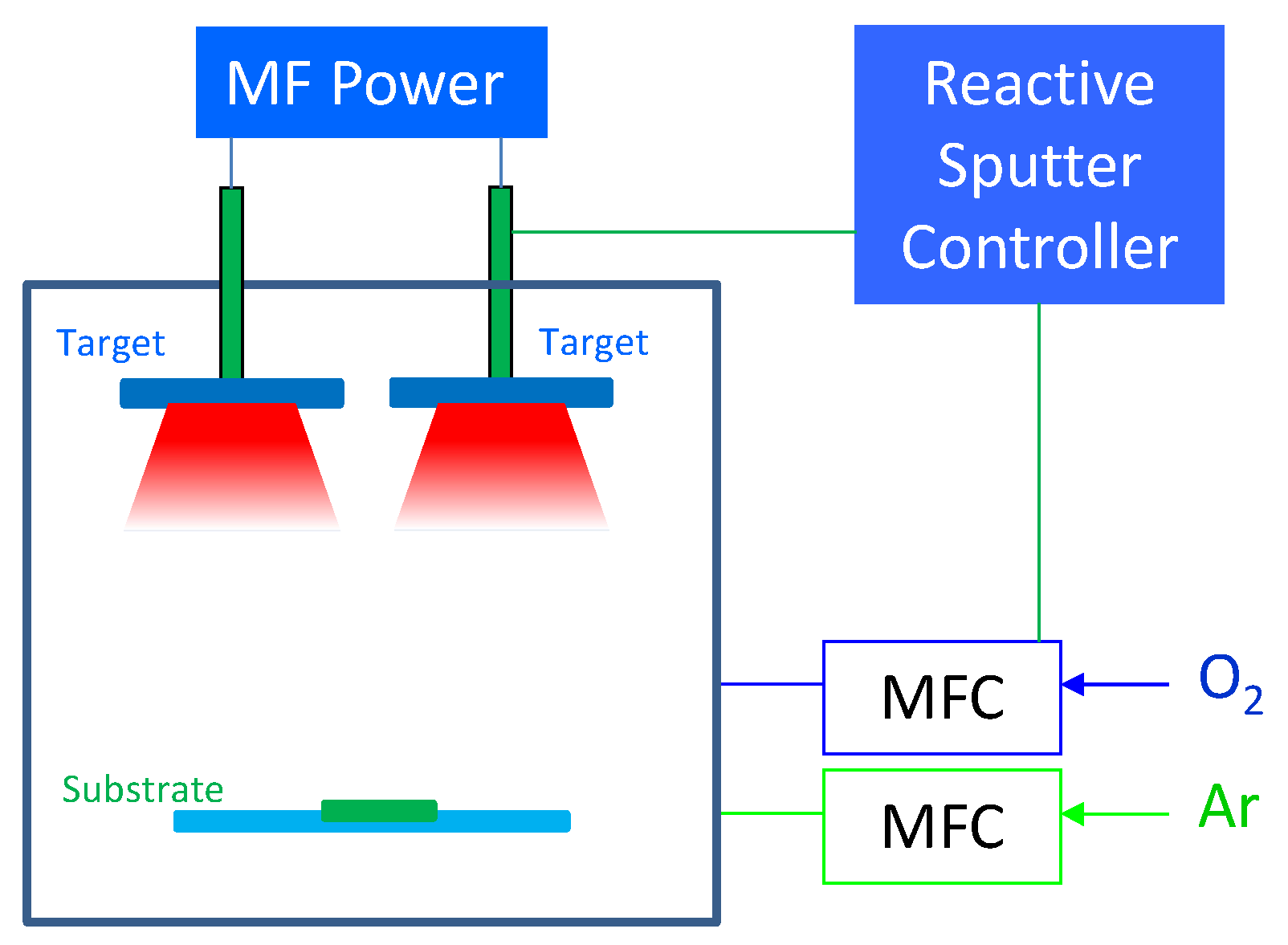
2.1. Sample Preparation
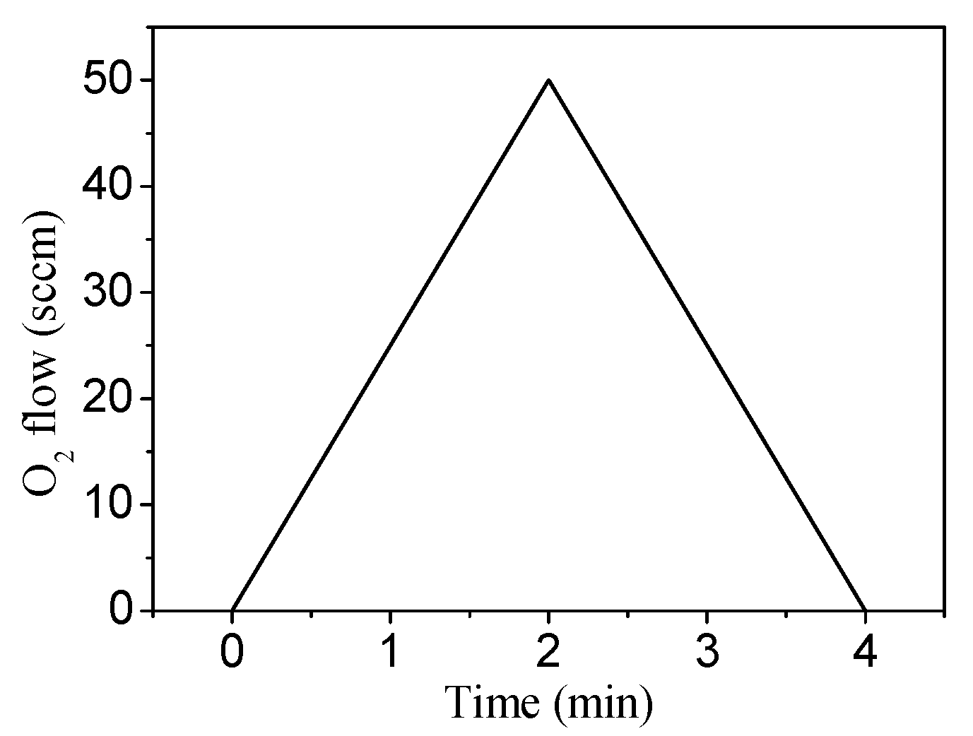
2.2. Target Voltage Hysteresis Loop Measurements
2.3. Film Characterization
3. Results
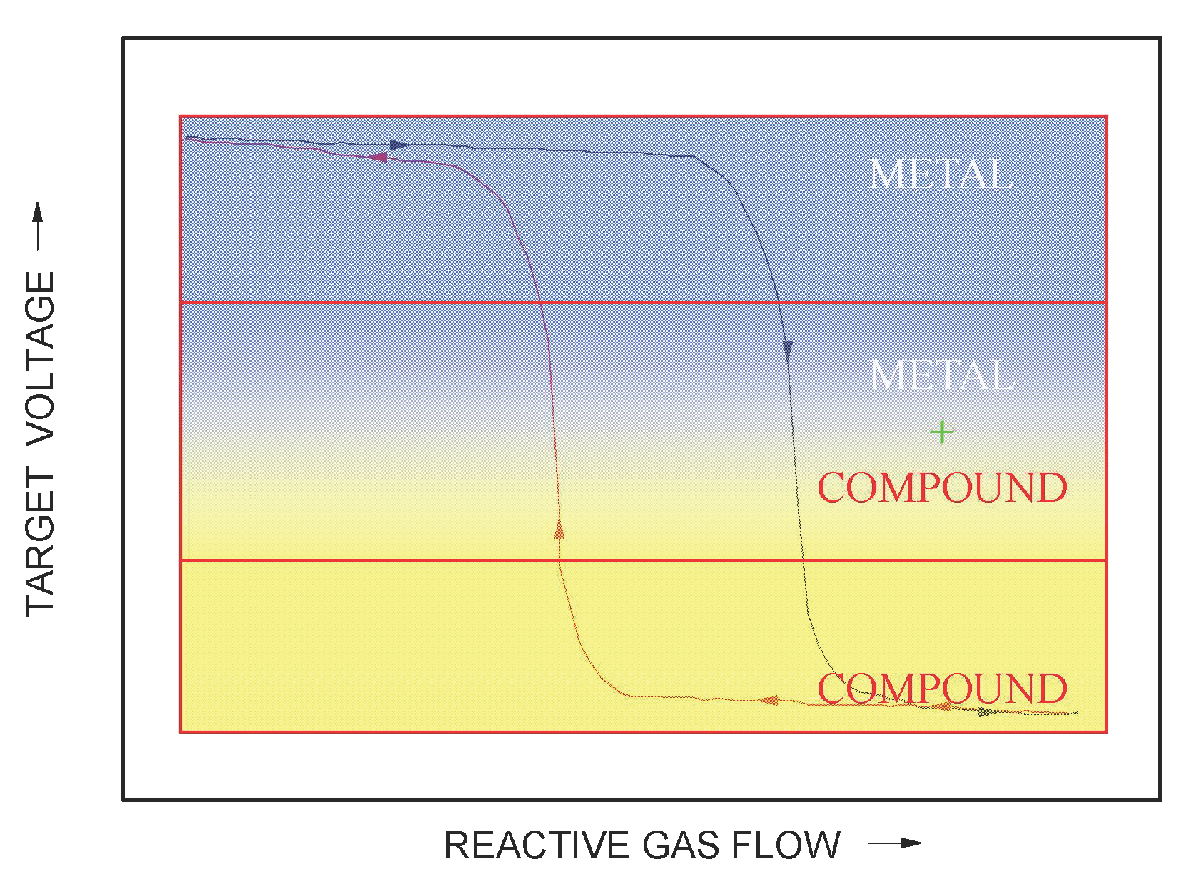
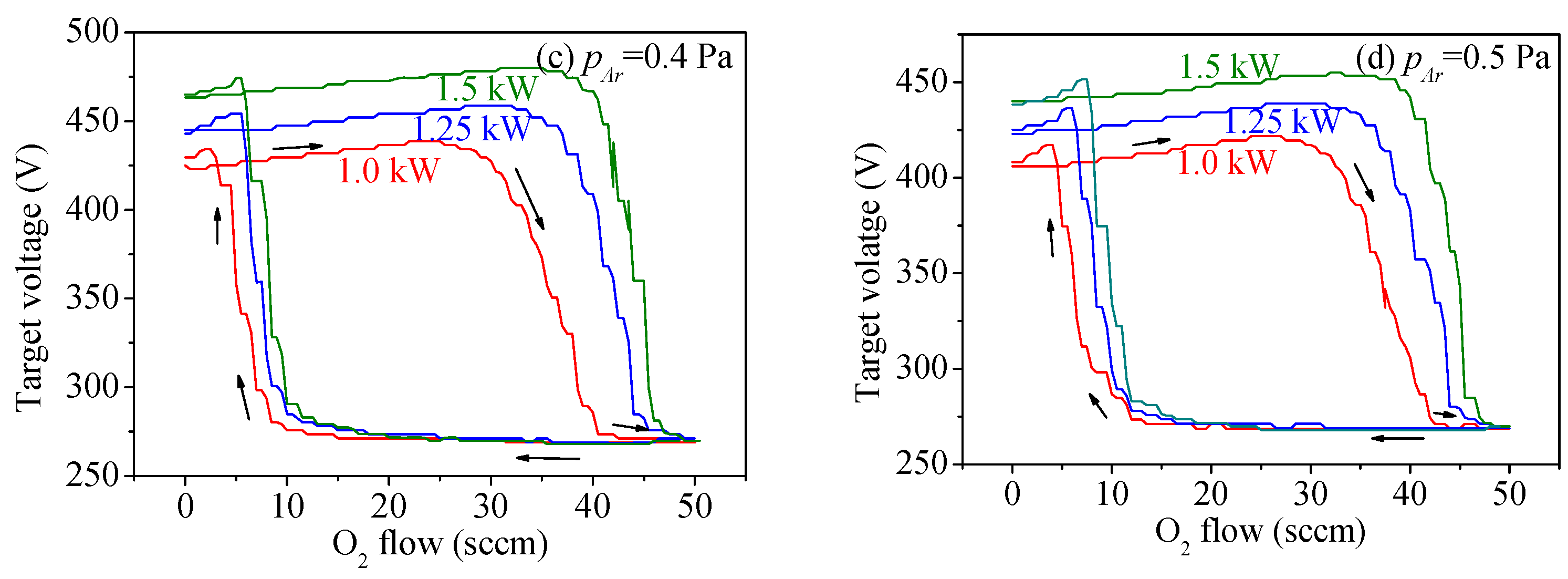
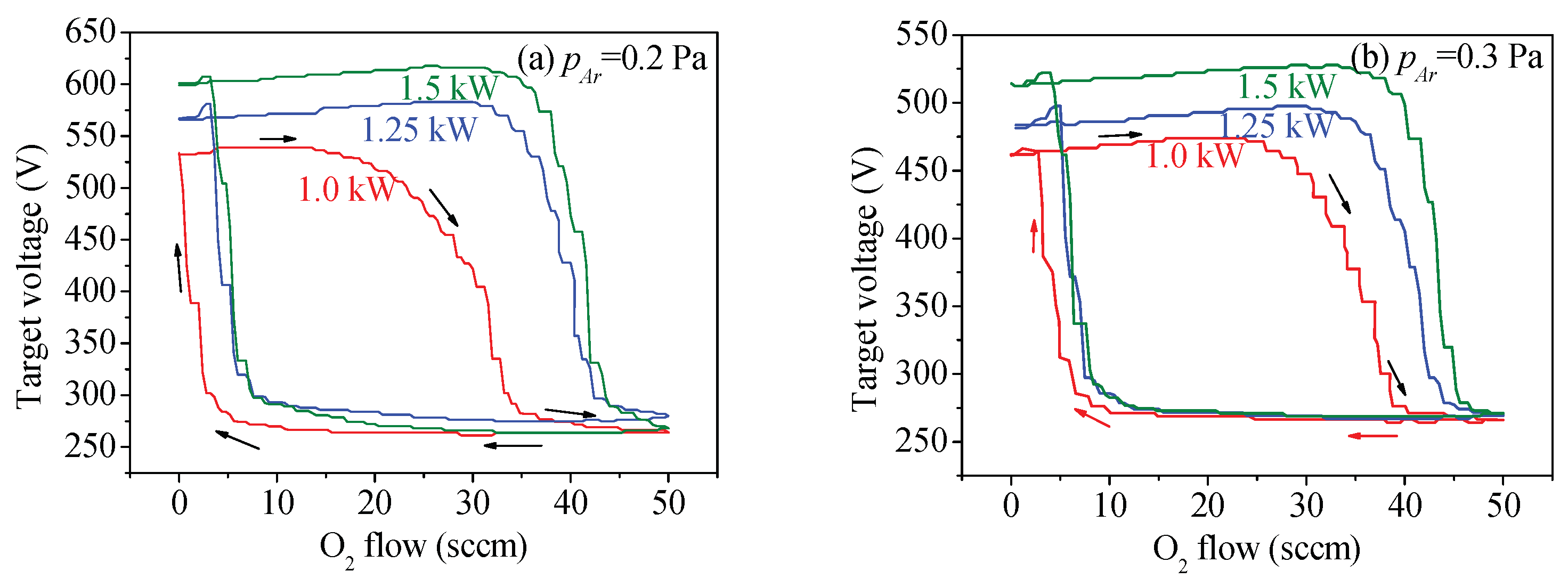
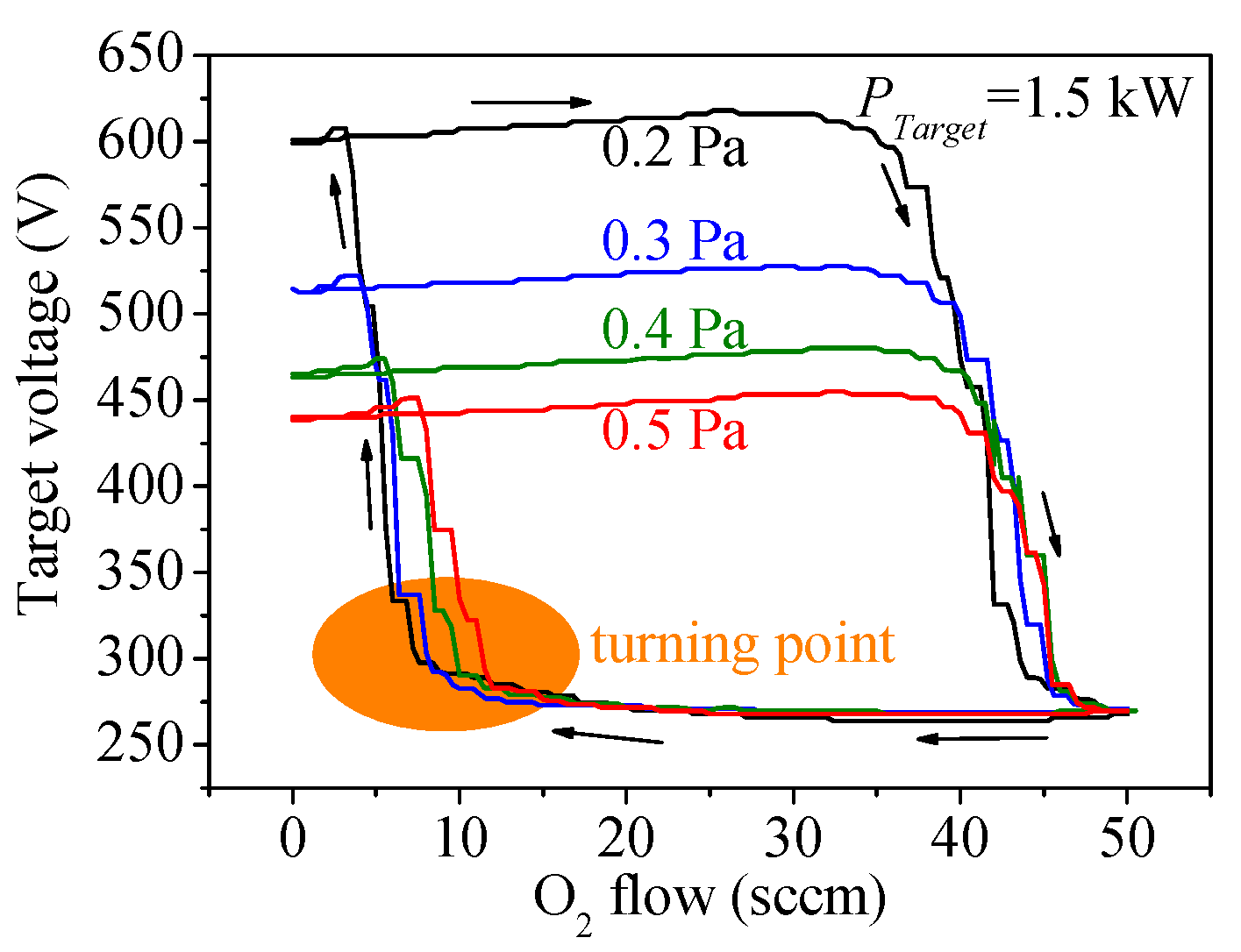
3.1. Target Voltage Hysteresis Loop
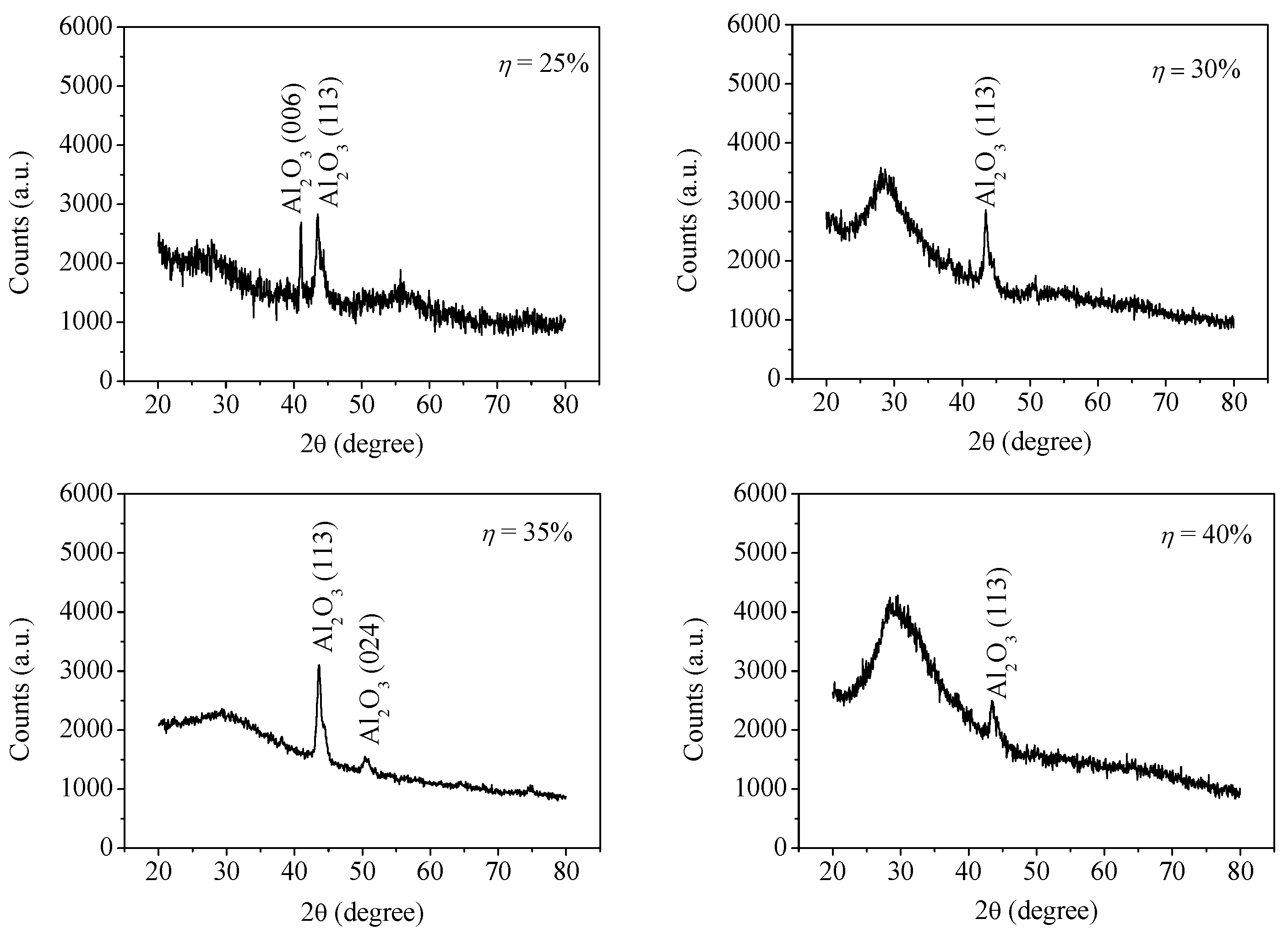
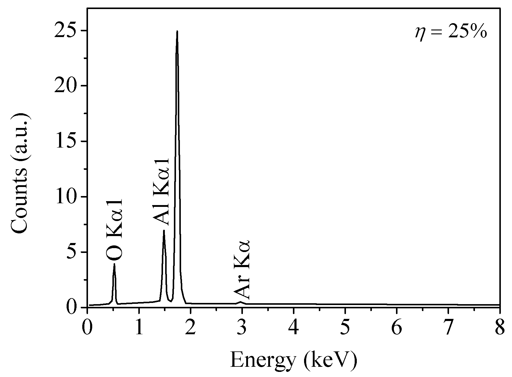
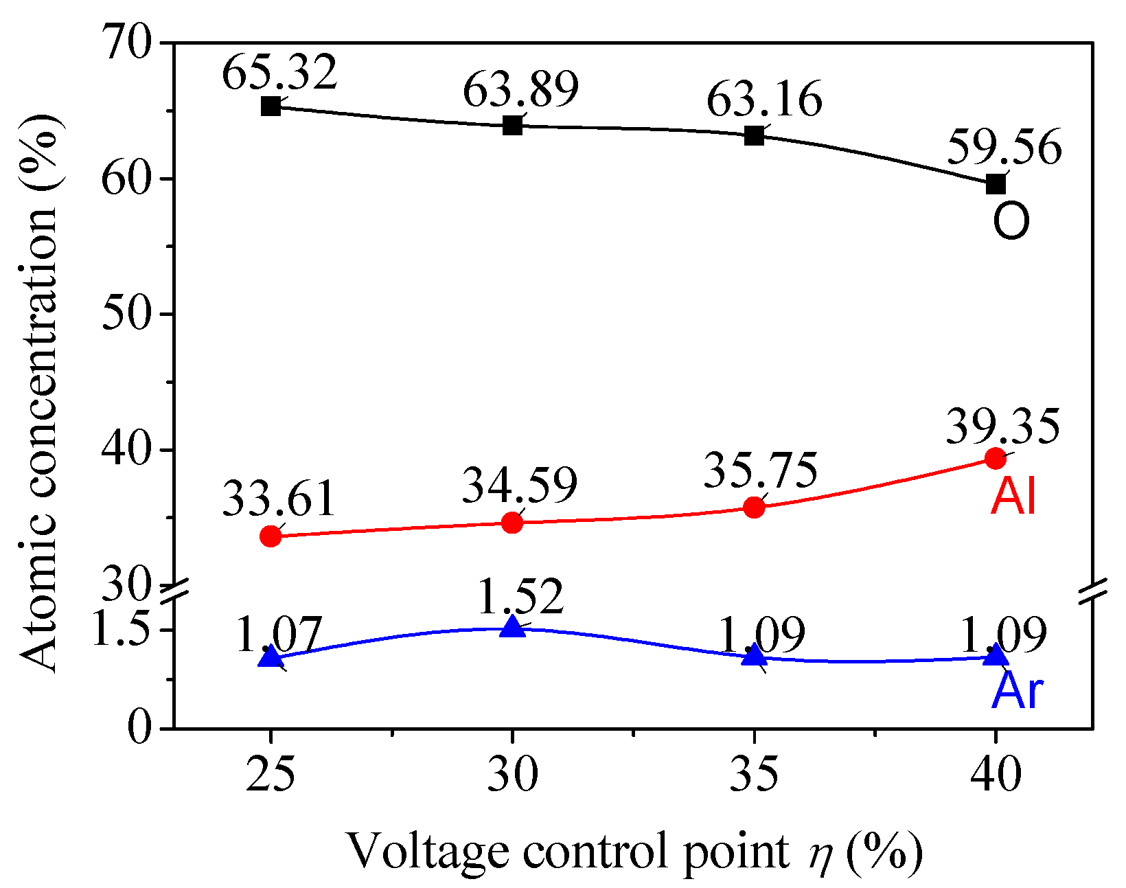
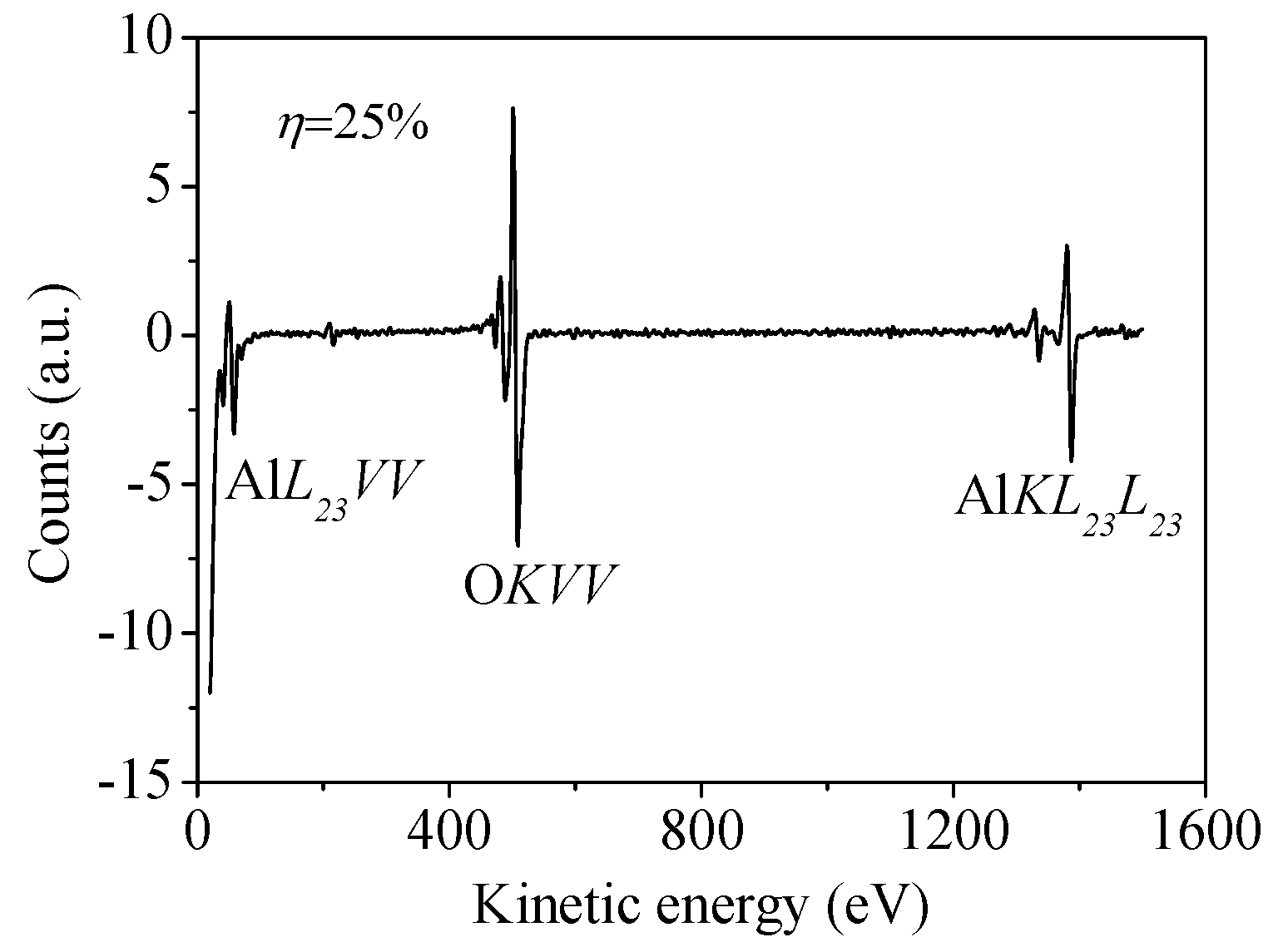
3.2. Target Voltage Control Point
4. Conclusions
Acknowledgments
Author Contributions
Conflicts of Interest
References
- Xin, Y.; Huo, K.; Hu, T.; Tang, G.; Chu, P.K. Mechanical properties of Al2O3/Al bi-layer coated AZ91 magnesium alloy. Thin Solid Films 2009, 517, 5357–5360. [Google Scholar] [CrossRef]
- Li, H.Q.; Wang, Q.M.; Gong, J.; Sun, C. Interfacial reactions and oxidation behavior of Al2O3 and Al2O3/Al coatings on an orthorhombic Ti2ALNb alloy. Appl. Surf. Sci. 2011, 257, 4105–4112. [Google Scholar] [CrossRef]
- Matikainen, V.; Niemi, K.; Koivuluoto, H.; Vuoristo, P. Abrasion, erosion and cavitation erosion wear properties of thermally sprayed alumina based coatings. Coatings 2014, 4, 18–36. [Google Scholar] [CrossRef] [Green Version]
- Ali, R.; Saleem, M.; Pääkkönen, P.; Honkanen, S. Thermo-optical properties of thin-film TiO2–Al2O3 bilayers fabricated by atomic layer deposition. Nanomaterials 2015, 5, 792–803. [Google Scholar] [CrossRef]
- Pfeiffer, K.; Schulz, U.; Tünnermann, A.; Szeghalmi, A. Antireflection coatings for strongly curved glass lenses by atomic layer deposition. Coatings 2017, 7, 118. [Google Scholar] [CrossRef]
- Lackner, J.; Waldhauser, W.; Major, L.; Kot, M. Tribology and micromechanics of chromium nitride based multilayer coatings on soft and hard substrates. Coatings 2014, 4, 121–138. [Google Scholar] [CrossRef]
- Yin, A.; Yan, J.; Chen, L.; Zhu, S.; Long, Z.; Fang, L.; Liu, T. Experimental and numerical investigation of buckling and delamination of Ti/TiN coatings on depleted uranium under compression. Appl. Surf. Sci. 2017, 422, 997–1006. [Google Scholar]
- Matthias, W.; Hoang Tung, D.; Hartmut, S.; Rainer, H. Aluminium atom density and temperature in a dc magnetron discharge determined by means of blue diode laser absorption spectroscopy. J. Phys. D Appl. Phys. 2005, 38, 2390–2395. [Google Scholar]
- Kulczyk-Malecka, J.; Kelly, P.; West, G.; Clarke, G.; Ridealgh, J. Characterisation studies of the structure and properties of as-deposited and annealed pulsed magnetron sputtered titania coatings. Coatings 2013, 3, 166–176. [Google Scholar] [CrossRef]
- Stefanov, B.; Österlund, L. Tuning the photocatalytic activity of anatase TiO2 thin films by modifying the preferred grain orientation with reactive dc magnetron sputtering. Coatings 2014, 4, 587–601. [Google Scholar] [CrossRef]
- Navabpour, P.; Cooke, K.; Sun, H. Photocatalytic properties of doped TiO2 coatings deposited using reactive magnetron sputtering. Coatings 2017, 7, 10. [Google Scholar] [CrossRef]
- Gao, W.; Li, Y.; Zhang, Y.; Yin, H. Exploration of growth window for phase-pure cubic boron nitride films prepared in a pure N2 plasma. Coatings 2018, 8, 82. [Google Scholar] [CrossRef]
- Safi, I. Recent aspects concerning dc reactive magnetron sputtering of thin films: A review. Surf. Coat. Technol. 2000, 127, 203–218. [Google Scholar] [CrossRef]
- Bräuer, G.; Szyszka, B.; Vergöhl, M.; Bandorf, R. Magnetron sputtering—Milestones of 30 years. Vacuum 2010, 84, 1354–1359. [Google Scholar] [CrossRef]
- Kouznetsov, V.; Macák, K.; Schneider, J.M.; Helmersson, U.; Petrov, I. A novel pulsed magnetron sputter technique utilizing very high target power densities. Surf. Coat. Technol. 1999, 122, 290–293. [Google Scholar] [CrossRef]
- Anders, A. Discharge physics of high power impulse magnetron sputtering. Surf. Coat. Technol. 2011, 205, S1–S9. [Google Scholar] [CrossRef]
- Stranak, V.; Herrendorf, A.-P.; Drache, S.; Cada, M.; Hubicka, Z.; Bogdanowicz, R.; Tichy, M.; Hippler, R. Plasma diagnostics of low pressure high power impulse magnetron sputtering assisted by electron cyclotron wave resonance plasma. J. Appl. Phys. 2012, 112, 093305. [Google Scholar] [CrossRef]
- Sproul, W.D.; Christie, D.J.; Carter, D.C. Control of reactive sputtering processes. Thin Solid Films 2005, 491, 1–17. [Google Scholar] [CrossRef]
- Depla, D.; Buyle, G.; Haemers, J.; De Gryse, R. Discharge voltage measurements during magnetron sputtering. Surf. Coat. Technol. 2006, 200, 4329–4338. [Google Scholar] [CrossRef]
- Berg, S.; Nyberg, T. Fundamental understanding and modeling of reactive sputtering processes. Thin Solid Films 2005, 476, 215–230. [Google Scholar] [CrossRef]
- Martin, P.M. Handbook of Deposition Technologies for Films and Coatings: Science, Applications and Technology; William Andrew: New York, NY, USA, 2009. [Google Scholar]
- Depla, D.; Mahieu, S.; De Gryse, R. Depositing aluminium oxide: A case study of reactive magnetron sputtering. In Reactive Sputter Deposition; Depla, D., Mahieu, S., Eds.; Springer: Berlin/Heidelberg, Germany, 2008; pp. 153–197. [Google Scholar]
- Smith, P.C.; Hu, B.; Ruzic, D.N. Low-energy ion-induced electron emission from gas-covered surfaces. J. Vac. Sci. Technol. A Vac. Surf. Films 1994, 12, 2692–2700. [Google Scholar] [CrossRef]
- Briggs, D.; Seah, M. Practical Surface Analysis: By Auger and X-ray Photoelectron Spectroscopy; Wiley: Hoboken, NJ, USA, 2003. [Google Scholar]


| Sample No. | Control Point (η) | Target Power (W) | Target Voltage (V) | Deposition Time (min) | Film Thickness (nm) | Estimated Average Grain Size (nm) |
|---|---|---|---|---|---|---|
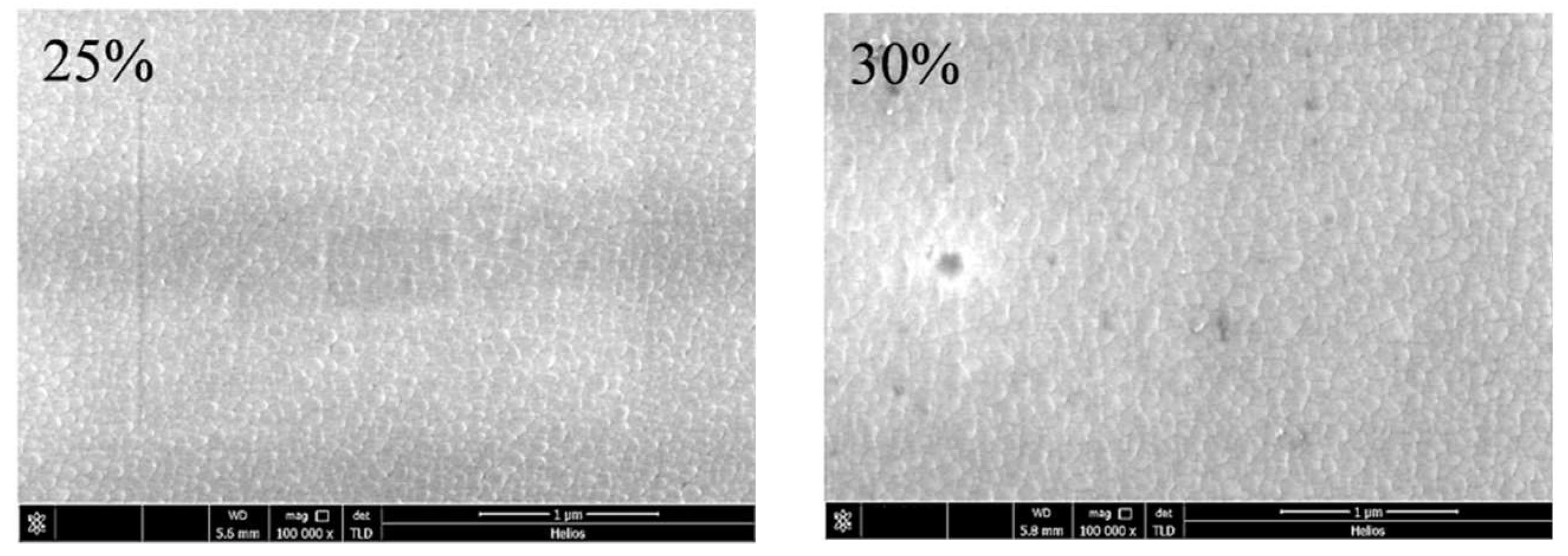
| 1 | 25% | 1500 | 412 | 60 | 506 | 84 |
| 2 | 30% | 451 | 591 | 89 | ||
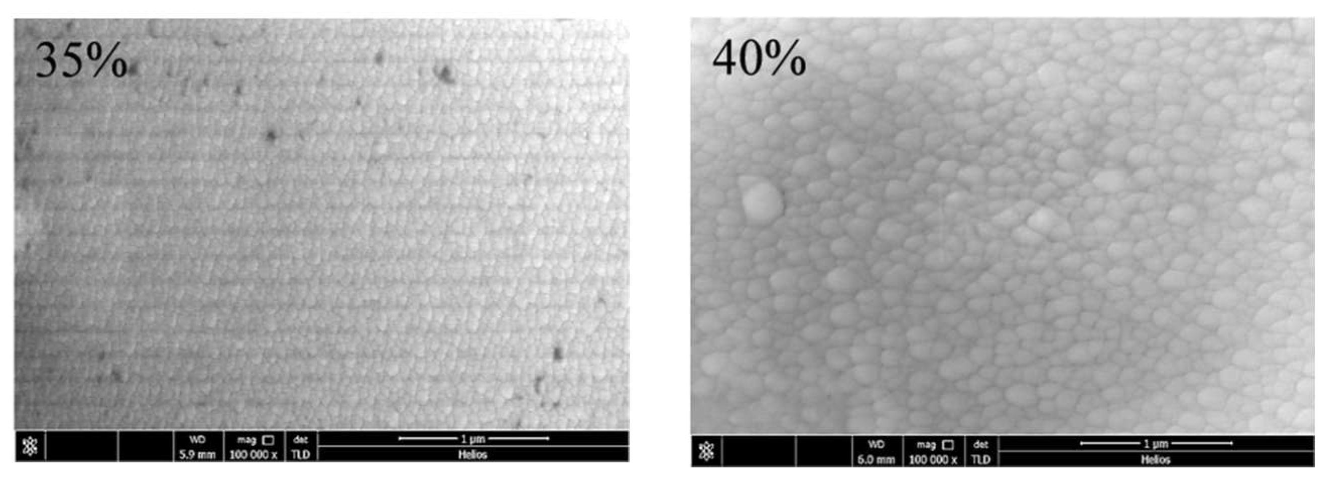
| 3 | 35% | 488 | 724 | 87 | ||
| 4 | 40% | 528 | 907 | 174 |
© 2018 by the authors. Licensee MDPI, Basel, Switzerland. This article is an open access article distributed under the terms and conditions of the Creative Commons Attribution (CC BY) license (http://creativecommons.org/licenses/by/4.0/).
Share and Cite
Wang, Q.; Fang, L.; Liu, Q.; Chen, L.; Wang, Q.; Meng, X.; Xiao, H. Target Voltage Hysteresis Behavior and Control Point in the Preparation of Aluminum Oxide Thin Films by Medium Frequency Reactive Magnetron Sputtering. Coatings 2018, 8, 146. https://doi.org/10.3390/coatings8040146
Wang Q, Fang L, Liu Q, Chen L, Wang Q, Meng X, Xiao H. Target Voltage Hysteresis Behavior and Control Point in the Preparation of Aluminum Oxide Thin Films by Medium Frequency Reactive Magnetron Sputtering. Coatings. 2018; 8(4):146. https://doi.org/10.3390/coatings8040146
Chicago/Turabian StyleWang, Qingfu, Liping Fang, Qinghe Liu, Lin Chen, Qinguo Wang, Xiandong Meng, and Hong Xiao. 2018. "Target Voltage Hysteresis Behavior and Control Point in the Preparation of Aluminum Oxide Thin Films by Medium Frequency Reactive Magnetron Sputtering" Coatings 8, no. 4: 146. https://doi.org/10.3390/coatings8040146