Microstructure and Properties of Cladding Layers Prepared by Argon-Shielded Arc Cladding of CuZn40-WC Powders on Pure Aluminum Substrate

1
School of Mechanical and Aerospace Engineering, Jilin University, Changchun 130025, China
2
College of Materials Science and Engineering, Jilin University, Changchun 130025, China
*
Author to whom correspondence should be addressed.
Coatings 2018, 8(11), 382; https://doi.org/10.3390/coatings8110382
Submission received: 8 September 2018
/
Revised: 4 October 2018
/
Accepted: 26 October 2018
/
Published: 27 October 2018
Abstract
:Aluminum and aluminum alloys have the advantage of a high strength-to-weight ratio, but their low hardness and poor wear resistance often cause wear damage. In the present study, the cladding layer was prepared using argon-shielded arc cladding of CuZn40-WC powders which were pre-coated on a pure aluminum substrate. The effects of WC proportion on the morphology, microstructure, and properties of cladding layers were investigated in detail. The results indicated that the optimal WC proportion in CuZn40-WC powders was 60 wt.%. With the increase of WC proportion, although the morphology of the cladding layer became slightly worse, the surface quality of the cladding layer was acceptable for industrial application until the WC proportion was 80 wt.%. Meanwhile, the top width and maximum depth of the cladding layer decreased. The maximum microhardness and optimal wear resistance of the cladding layer were 4.5 and 2.5 times that of the aluminum substrate, respectively. The increased microhardness and wear resistance were mainly attributed to the formation of Al4W in the cladding layer. The wear scar of the high wear resistance specimen was smoother and some bulk Al4W compounds were clearly observed on the wear surface.
1. Introduction
Due to the demands for lightweight, energy-saving, and environmentally friendly materials, aluminum and aluminum alloys are increasingly applied in mechanical engineering, automobile, rail traffic, aerospace, shipping, and other industrial fields [1,2,3]. However, the shortcomings of a poor wear resistance, low strength, and low melting point have limited their extensive application. For example, high hardness, wear resistance, and high temperature resistance are required for cylinder and friction pair parts, and an aluminum alloy is difficult to apply. Therefore, improvement of the wear resistance and high temperature resistance of aluminum alloy surfaces has become an important issue [4,5,6].
At present, laser and arc heat sources are mainly used for the surface strengthening and treatment of aluminum and aluminum alloys. Ravi et al. [7] studied laser surface alloyed aluminum with Ni-Cr powder. The results showed that metallurgical bonding was formed between the cladding layer and the substrate without crack defects, and the microhardness of the cladding layer increased with the increasing Cr concentration. Ye et al. [8] prepared an Fe-Al intermetallic coating on an aluminum alloy substrate by laser cladding, and the composite cladding layer consisted of α-Al, FeAl, FeAl3, Fe2Al5, and Fe3Al phases. Compared with the aluminum substrate, the microhardness of the cladding layer was greatly improved, and the maximum hardness reached up to 890 HV. Jendrzejewski et al. [9] performed laser cladding of SiC and WC powders on an aluminum alloy by synchronous powder feeding, and the cladding layers had no defects and were more wear and corrosion resistant than the aluminum alloy substrate. Ouyang et al. [10] conducted laser cladding of yttria partially stabilized ZrO2 (YPSZ) ceramic coatings on three different aluminum alloys (AlSi9Cu3, AlZn10Si8Mg, and AlSi10Mg alloys), and ZrO2 ceramic coatings with a low dilution ratio and high hardness were obtained, but there were pore and crack defects. Man et al. [11] put forward a process to prepare a composite layer on a 6061 aluminum alloy by laser cladding technology. The pre-coated Ti-C-W-WC mixed powders were laser cladded using a coaxial nozzle to synchronously feed Ni-Al-Al2O3 mixed powders, and the Ni-Al-based composite layer was obtained by in-situ synthesis of TiC and WC particles. Nath et al. [12] achieved laser surface alloying of commercially pure aluminum with WC-Co-NiCr powders. The alloyed layer without defects and a uniform microstructure was successfully prepared under the optimum process parameters, and the microhardness of the alloyed layer was greatly increased compared with the aluminum substrate. Although the application of laser cladding on aluminum and aluminum alloys is very popular, it is also limited because of the easy occurrence of pore and crack defects, as well as the high cost of laser equipment and operating. Arc cladding technology has the advantages of being low-cost and easy to operate, and having a high production efficiency, and thus has gradually become one of the choices for aluminum alloy surface cladding [13,14,15]. Lotfi et al. [16] used the tungsten inert gas (TIG) welding process to fabricate an Al-Si/SiCp composite layer on an aluminum substrate with Al, Si, and SiC mixed powders. They found that the SiC particles distributed evenly on the aluminum matrix and the hardness and wear resistance of the cladding layer was improved with the additional silicon, due to the formation of eutectic silicon particles. Tang et al. [17] prepared TiC particles in the cladding layer of a 1060 Aluminum alloy by an in-situ synthesis method using an argon-shield arc heat source. Good metallurgical bonding was formed between the cladding layer and the substrate, with a large current parameter and without pore or crack defects. The cladding layer was composed of α-Al, TiC, and a small amount of Al3Ti and Al4C3. However, to date, research on argon-shield arc cladding of aluminum alloys is limited.
In previous literature, aluminum surface strengthening was mostly limited to aluminum alloys. Compared with aluminum alloys, pure aluminum is lighter weight, and displays better heat transfer, conductivity, and corrosion resistance, but its hardness and strength are lower, so it has a greater requirement for surface strengthening. Therefore, pure aluminum was chosen as the substrate material in the present study. The cladding materials used for the surface modification of aluminum and aluminum alloys were mainly Ni-based, Cu-based, and Fe-based alloy powders with a certain amount of ceramic phase powders, such as Al2O3, SiC, TiC, and WC [18,19,20,21]. On the basis of good wettability between the Cu-Zn alloy and WC, and good wettability and compatibility between the Cu-Zn alloy and Al, CuZn40-WC mixed powders were employed to prepare cladding layers on the pure aluminum substrate using the argon-shield arc technique. The effects of the composition of CuZn40-WC mixed powders on the morphology, microstructure, and properties of cladding layers were investigated in detail.
2. Materials and Methods
In the present study, the pure aluminum plate was used as the substrate, with dimensions of 60 mm × 25 mm × 8 mm. As shown in Figure 1, the microstructure of the pure aluminum substrate displays a distinct grain and grain boundary, and the X-ray diffractometer (XRD) analysis indicates that the pure aluminum substrate is only comprised of an α-Al phase. The cladding material is CuZn40 and WC powders, and the scanning electron microscopy (SEM) images are shown in Figure 2. The average size of CuZn40 powder is 20 μm, and the average size of WC powder is 2 μm.
Firstly, the pure aluminum plates were sanded with SiC sandpaper to remove the oxide film, and were then wiped with acetone to remove oil and debris. The CuZn40 powder and WC powder with different proportions were mixed evenly, and the proportion of WC powder in the CuZn40-WC mixed powders ranged from 0 to 80%. The CuZn40-WC powders were pre-coated in pure aluminum substrate with a 0.6 mm thickness. The powder pre-coating method was as follows: a mould with dimensions of 60 mm × 15 mm × 0.6 mm was placed on the substrate surface, and the powders then were placed and filled within the mould; secondly, a proper amount of sodium silicate solution was poured into the powders to bond them together and adhere them to the substrate surface; finally, the samples were dried naturally for 24 h and put into the oven at 100 °C for 2 h, and then cooled to room temperature for later use. The argon-shielded arc provided by a direct current using the WP-300 Tungsten Inert Gas (TIG) welding machine was employed to clad the pre-coated CuZn40-WC powders and prepare the cladding layer on the pure aluminum substrate. During the arc cladding process, the tungsten pole and specimen were connected to the negative and positive terminals of the welding power source, respectively. The schematic diagram of the argon-shielded arc cladding process is shown in Figure 3. The main parameters of the argon-shielded arc cladding process are listed in Table 1.
After cladding, the samples were transversely sectioned, and then mounted, polished, and etched for microstructure observation. The etch solution consisted of 1 ml HCl, 1 ml HF, and 8 ml H2O. The optical microscope (Axio Scope.A1, ZEISS, Jena, Germany) and scanning electron microscope (SEM) (JXA-840, JEOL, Tokyo, Japan) with an energy dispersive spectrometer (EDS) were employed to observe the microstructure characteristics and to analyze the chemical compositions. The EDS analysis was performed using a 20 kV accelerating voltage, 35 μA emission current, and 10.5 mm working distance, and the images were obtained in the secondary electron imaging mode. The phase structure was measured using an X-ray diffractometer (XRD) (D/MAX-2500PC, Rigaku, Tokyo, Japan) machine and the main operating parameters included a 40 kV voltage, 250 mA current, Cu Kα radiation, 0.02° angle step-length, and 4°/min scanning rate. The microhardness was measured on the cross-section of the cladded specimen by the hardness testing machine (Everone MH-3, Everone Enterprises, Ltd., Nanjing, China) and the load and load time were 100 g and 10 s, respectively. The specimens with dimensions of 5 mm × 5 mm × 8 mm (wear test surface was 5 mm × 5 mm, and holding height was 8 mm) were prepared to conduct the wear experiment at room temperature. The two-body abrasive experiment was performed using an abrasive wear test machine (ML-100, Jinan Jingcheng Testing Technology Company, Jinan, China) and the schematic diagram of the wear experiment is indicated in Figure 4. Six-hundred-grit SiC sandpaper was employed as a friction counterpart and the constant normal load was 3 N. Each wear test was performed with the same stroke of 20 m. The wear resistance was evaluated according to the weight loss of the wear specimen. Finally, the wear surface was observed by the SEM-JXA840.
3. Results and Discussion
3.1. Morphology of Cladding Layer
The morphology of the typical cladding specimen is shown in Figure 5. The cladding layers are all gray except for that prepared with 100% CuZn40 powder, which is yellow (the color of Al-Cu-Zn alloy). When the CuZn40 proportion in the mix powders was large, the cladding layer was very smooth, but as the WC proportion was increased, spherical particles, voids, and poor fusion defects appeared on the cladding layer surface. Because of the low melting point of CuZn40 powder (967 °C) and the high mutual solubility between Cu, Zn, and Al, the CuZn40 powder was prone to melt and dissolve with aluminum or produce a small amount of compounds, and so the flow of the melting pool was relatively stable during the cladding process with the high CuZn40 proportion powders. Owing to the high melting point of WC powder (2870 °C), a large part of WC powders was not melted by the arc and moved to the melting pool, which resulted in an unstable flow of the melting pool and in defects during the cladding process with the high WC proportion powders. Although the morphology of the cladding layer deteriorated slightly with increasing WC proportion, the surface quality of the cladding layer would be acceptable for industrial application until the WC proportion was 80 wt.%. The surface of the cladding layer should then be performed with fine grinding for subsequent industrial application. Figure 6a shows the typical morphology of the cladding layer cross-section. The top width (W) and maximum height (H) of the cladding layer were used to evaluate the effect of the composition proportion of CuZn40-WC powders on the cladding layer morphology. On the whole, the top width (W) and maximum height (H) of the cladding layer decreased with increasing WC proportion in the CuZn40-WC powders, as shown in Figure 6b. While the WC proportion was no more than 40 wt.%, the decreases of W and H were obvious with the increase of WC proportion, and subsequently became relatively constant. In this study, the parameters of the argon-shielded arc were constant, namely, the total heat input was constant. Therefore, while the WC proportion in CuZn40-WC powders was smaller, the argon-shielded arc heat was mostly used for the melting of CuZn40 powder and aluminum substrate, which resulted in larger W and H. While the WC proportion in CuZn40-WC powders was larger, more heat was expended to melt the CuZn40 powder and in particular the WC powder, and the aluminum substrate exhibited less melting. Consequently, the W and H became smaller.
3.2. Microstructure of Cladding Layer
The microstructures of the cladding layers prepared by the argon-shielded arc cladding of the CuZn40-WC powders with different proportion components are indicated in Figure 7. While the cladding powder was 100 wt.% CuZn40 powder, the microstructure of the cladding layer was homogeneous, which was similar to that of the aluminum substrate, as shown in Figure 7a, and the cladding layer was comprised of α-Al solid solution (containing Cu and Zn elements) and a small amount of Al-Cu compound. While the low proportion (≤30 wt.%) of WC powder was mixed with CuZn40 powder and used to clad, the cladding layers were also mainly comprised of α-Al solid solution. However, there were small amounts of agglomerated CuZn40 and WC powders in the cladding layers, as shown in Figure 7b. Figure 8 shows the SEM microstructure and EDS analysis results of line scanning in the typical local zone of Figure 7b. The results indicated that there were large amounts of W and Zn elements and small amounts of Cu and Al elements, which should be melted CuZn40 powder and non-melted WC powder infiltrated with a small amount of aluminum melt at point A. At point B, there was a large amount of Al and a small amount of W element, which was an Al-W compound with a maximum size of around 8 μm. Point C should be located at the grain boundary of the α-Al solid solution, which contained a large amount of Al and Cu elements and represents the low melting point eutectic compound of Al-Cu.
While the WC proportion increased to 60 wt.%, the cladding layer mainly consisted of the α-Al matrix and many bulk Al4W compounds, as shown in Figure 7c and Figure 9. Figure 10 displays the SEM image and EDS results of the cladding layer prepared with 40 wt.% CuZn40 and 60 wt.% WC powders. The results showed that there were large amounts of Al and W elements at point “a” and point “d”, and so the lath and bulk structures were an Al4W compound. Meanwhile, a large amount of Al and Cu elements existed at point “b” and point “c” located on the grain boundary of the α-Al matrix, and were Al-Cu and Al-Cu-Zn compounds. During the argon-shielded arc cladding process with high WC proportion powders (e.g., ≥60 wt.%), only small parts of WC powders were heated, melted, and decomposed, which then constantly dissolved and diffused into the matrix, and reacted with Al and other elements. Because of the substantial difference in the density, melting point, and poor wettability between the liquid Al and C, the Al-C compound (Al4C3) was not found in the cladding layer. The Al and W can react to form a variety of Al-W compounds, such as Al7W3, Al77W23, Al12W, Al5W, and Al4W, and the minimum Gibbs free energy required to form different Al-W compounds is Al4W. Namely, Al4W is the most easily generated Al-W compound when the W content satisfies the formation conditions [22,23]. When the WC proportion was 60 wt.%, the composition in most of the melt pool regions satisfied the formation conditions of the Al4W compound, and thus there were a large number of Al4W compounds with a maximum size of around 35 μm in the cladding layer.
When the WC proportion increased to 80 wt.%, the cladding layer was mainly comprised of α-Al solid solution and bulk Al4W compound, and the maximum size of Al4W was around 60 μm, as shown in Figure 7d. However, because of the poor wettability between high WC proportion powders and the aluminum matrix, the quantity of WC powder entering the cladding molten pool decreased, resulting in a decrease of the quantity of Al4W compound.
3.3. Microhardness
The microhardness experiments were carried out on a cross-section of the cladding layer, and the schematic diagram of microhardness test is shown in Figure 11. The average microhardness values of the cladding layers prepared using the different WC proportions are indicated in Figure 12. During the microhardness test, when there was a small amount of agglomerated CuZn40-WC powders and non-molten WC powder in the cladding layers, the individual microhardness values were higher than 1100 HV0.3 due to the existence of WC particles which had a very high hardness. Because the ultra-high microhardness values were individual and were in the minority, they were not included in the calculation of the average microhardness values of the cladding layers. As shown in Figure 12, compared with the aluminum substrate (27 HV0.3), the average microhardness values of the cladding layers all increased. As the WC proportion increased from 0 to 60 wt.%, the microhardness of the cladding layer increased and reached a maximum value of 122 HV0.3, which was 4.5 times that of the aluminum substrate. However, as the WC proportion continued to increase, the microhardness of the cladding layer decreased slightly. According to the microstructure analysis of the cladding layer described in Section 3.2, as the WC proportion was increased, the strengthening phases (especially Al4W) in the cladding layers gradually increased. Therefore, the improvement of the microhardness was mainly attributed to the increase of the strengthening phases in the cladding layer.
3.4. Wear Resistance
Wear resistance was carried out by the abrasive wear test, as described in Section 2. Five specimens prepared by each of the CuZn40-WC mixed powders were performed on the wear resistance test, and the average value of weight loss was obtained to evaluate the wear resistance of the cladding layer. The effect of the WC proportion on the weight loss of the wear resistance specimen is shown in Figure 13. The results show that the greatest weight loss was the aluminum substrate, indicating that all cladding layers had a better wear resistance than the pure aluminum substrate. The weight loss of the cladding layer decreased substantially with increasing WC proportion and decreased to the minimum at 60 wt.%. When the WC proportion continued to increase, the weight loss increased. It is well-known that the smaller the weight loss of a specimen is, the better its wear resistance is. Therefore, when the WC proportion was 60%, the wear resistance of the cladding layer was optimal, which was 2.5 times that of the aluminum substrate. The results of the wear resistance test correspond to the effect of the WC proportion on microstructure and microhardness; that is, the larger the size and quantity of the compound strengthening phase (especially Al4W) in the cladding layer, the better the wear resistance.
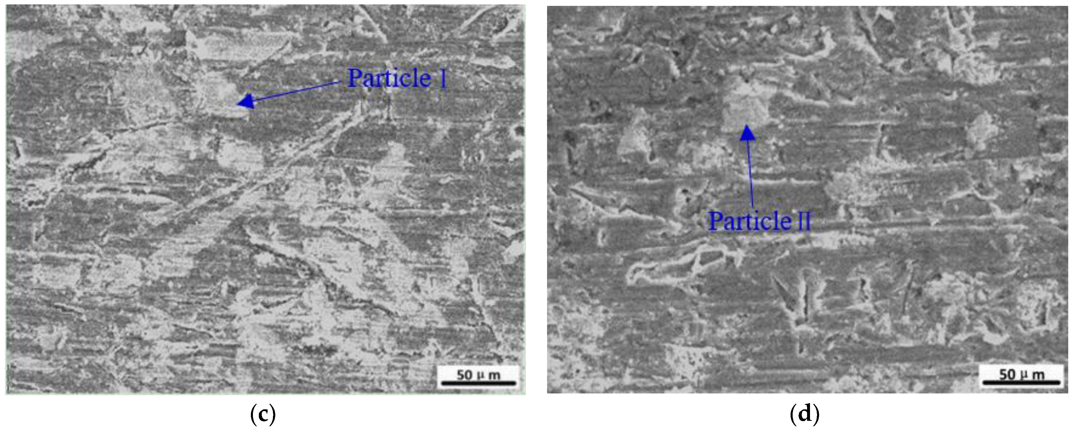
The wear morphology indicates the wear resistance and wear mechanism of specimens. The morphology of abrasive wear is mainly furrow and some concave pits were formed by the separation of material. The smaller the quantity of furrows and shallow concave pits, the better the wear resistance [24]. Figure 14 shows the typical wear morphology of the aluminum substrate and some cladding layers. The wear specimen of the aluminum substrate had many furrow wear scars, which were wider and deeper than those in the cladding layers. According to Figure 13 and Figure 14, the better the wear resistance of the specimen, the fewer furrow wear scars and concave pits, and the smaller the depth and width, which were consistent with the microhardness and weight loss results. The cladding layers prepared with high WC proportion powders had a good wear resistance, and their wear surfaces had some bulk particles, as shown in Figure 14c,d. Energy dispersive spectrometer analysis was carried out on particle I and particle II. The EDS results are given in Table 2, which indicates that the bulk of the particles are an Al4W compound. The Al4W particle has a high hardness, and the improvement in wear resistance is attributed to the existence of a large number of Al4W particles, as shown in Figure 14c.
4. Conclusions
In this study, the argon-shielded arc was employed to clad the CuZn40-WC powders on a pure aluminum substrate to prepare a composite cladding layer, and the effects of powder composition on the microstructure and properties of the cladding layer were investigated. The main conclusions are as follows.
With the constant cladding process parameters and an increase in the WC proportion in CuZn40-WC powders, the morphology of the cladding layer could be accepted for industrial application when the WC proportion was below 80 wt.%, and the top width and maximum depth of the cladding layer decrease. This is because, when the WC proportion was high, more heat was expended to melt the WC powder, and the wettability between the melted powder and aluminum substrate was poor.
During the argon-shielded arc cladding process, most of the pre-coated powders were melted by arc heating and several were agglomerated and then mixed with the molten aluminum substrate. When the WC proportion was less than 60 wt.%, the cladding layer was mainly composed of α-Al solid solution, a small amount of Al4W compound, and agglomerated CuZ40-WC powders. When the WC proportion was greater than or equal to 60 wt.%, the cladding layer was mostly comprised of α-Al and a large number of Al4W existed in shapes of lath and bulk. With an increased WC proportion, the quantity and size of the Al4W compound increased, and the morphology of the Al4W transited from granular to lath and bulk. When the WC proportion was increased to 80 wt.%, the maximum size of the Al4W compound could be up to 60 μm.
With the increase of WC proportion in the pre-coated powders, the microhardness and wear resistance of the cladding layer all increased at first and then decreased slightly. When the WC proportion was 60 wt.%, the microhardness and wear resistance reached their maximum. The maximum average microhardness of the cladding layer was 122 HV0.3, which was 4.5 times that of the pure aluminum substrate. The optimal wear resistance of the cladding layer was 2.5 times that of the substrate. The wear scar of high wear resistance specimen was smoother and some bulk Al4W compounds were clearly observed on the wear surface.
The cladding layer on the aluminum substrate with a high wear resistance was successfully prepared using the argon-shielded arc cladding process with 40 wt.% CuZn40 plus 60 wt.% WC mixed powders. The present research results provide a new technology for aluminum surface strengthening, which would help to promote the wider application of aluminum in engine piston-cylinder parts, the drill pipe of a pumping unit, armature-guide rail parts of electromagnetic railgun launch, and other industrial fields, because of its high quality, low cost, and high efficiency.
Author Contributions
Writing, Investigation, and Funding Acquisition: X.Z.; Validation and Investigation: Q.S.; Conceptualization, Methodology and Supervision: Z.R.; Formal Analysis: G.L.
Funding
This research was funded by the Jilin Scientific and Technological Development Program (No. 20160520055JH).
Acknowledgments
The work was supported by the program for the JLU Science and Technology Innovative Research Team (JLUSTIRT) and Key laboratory of Automobile Materials of Ministry of Education (Jilin University).
Conflicts of Interest
The authors declare no conflict of interest.
References
- Miller, W.S.; Zhuang, L.; Bottema, J.; Wittebrood, A.; De Smet, P.; Haszler, A.; Vieregge, A. Recent development in aluminium alloys for the automotive industry. Mater. Sci. Eng. A 2000, 280, 37–49. [Google Scholar] [CrossRef] [Green Version]
- Zhang, X.; Li, L.; Chen, Y.; Yang, Z.; Chen, Y.; Guo, X. Effects of pulse parameters on weld microstructure and mechanical properties of extra pulse current aided laser welded 2219 aluminum alloy joints. Materials 2017, 10, 1091. [Google Scholar] [CrossRef] [PubMed]
- Heinz, A.; Haszler, A.; Keidel, C.; Moldenhauer, S.; Benedictus, R.; Miller, W.S. Recent development in aluminium alloys for aerospace applications. Mater. Sci. Eng. A 2000, 280, 102–107. [Google Scholar] [CrossRef]
- Xu, J.; Liu, W.; Kan, Y.; Zhong, M. Microstructure and wear properties of laser cladding Ti–Al–Fe–B coatings on AA2024 aluminum alloy. Mater. Des. 2006, 27, 405–410. [Google Scholar] [CrossRef]
- He, H.; Guo, W.H.; Xiao, M.; Pang, X.Z.; Shen, X.M.; Fu, Y.C.; Zeng, J.M. Effect of laser cladding Al3Ti-based coatings on the wear and corrosion resistances of AA6063 aluminum alloy. Adv. Mater. Res. 2013, 652–654, 1897–1903. [Google Scholar] [CrossRef]
- Liu, C.L.; Lv, Y.H.; Xiang, Y.H.; Xia, D.; Xu, B.S. Microstructures and properties of aluminum alloy cladding deposited by variable polarity plasma arc overlaying. China Surf. Eng. 2009, 22, 37–40. [Google Scholar]
- Ravi, N.; Sastikumar, D.; Subramanian, N.; Nath, A.K.; Masilamani, V. Microhardness and microstructure studies on laser surface alloyed aluminum alloy with Ni-Cr. Adv. Manuf. Process. 2000, 15, 395–404. [Google Scholar] [CrossRef]
- Ye, H.; Peng, S.X.; Yan, Z.L.; Zhang, X.B. Microstructure and properties of laser cladding Fe-Al intermetallics. Adv. Mater. Res. 2013, 659, 39–42. [Google Scholar] [CrossRef]
- Jendrzejewski, R.; Van Acker, K.; Vanhoyweghen, D.; Śliwiński, G. Metal matrix composite production by means of laser dispersing of SiC and WC powder in Al alloy. Appl. Surf. Sci. 2009, 255, 5584–5587. [Google Scholar] [CrossRef]
- Ouyang, J.H.; Nowotny, S.; Richter, A.; Beyer, E. Laser cladding of yttria partially stabilized ZrO2 (YPSZ) ceramic coatings on aluminum alloys. Ceram. Int. 2001, 27, 15–24. [Google Scholar] [CrossRef]
- Man, H.C.; Yang, Y.Q.; Lee, W.B. Laser induced reaction synthesis of TiC+WC reinforced metal matrix composites coatings on AA 6061. Surf. Coat. Techol. 2004, 185, 74–80. [Google Scholar] [CrossRef]
- Nath, S.; Pityana, S.; Majumdar, J.D. Laser surface alloying of aluminium with WC + Co + NiCr for improved wear resistance. Surf. Coat. Technol. 2012, 206, 3333–3341. [Google Scholar] [CrossRef]
- Ureña, A.; Escalera, M.D.; Gil, L. Influence of interface reactions on fracture mechanisms in TIG arc-welded aluminium matrix composites. Compos. Sci. Technol. 2000, 60, 613–622. [Google Scholar] [CrossRef]
- Wang, X.H.; Niu, J.T.; Guan, S.K.; Wang, L.J.; Cheng, D.F. Investigation on TIG welding of SiCp-reinforced aluminum–matrix composite using mixed shielding gas and Al–Si filler. Mater. Sci. Eng. A 2009, 499, 106–110. [Google Scholar]
- Wu, J.; Chen, S.M.; Sun, Z.F.; Ding, Z.B.; Sun, S.L. Research on technologies for surface deposited metal powders aluminum alloy with TIG. J. Wuhan Automot. Polytech. Univ. 1998, 20, 16–18. [Google Scholar]
- Lotfi, B.; Rostami, M.; Sadeghian, Z. Effect of silicon content on microstructure of Al-Si/SiCp composite layer cladded on A380 Al alloy by TIG welding process. Trans. Nonferrous Met. Soc. China 2014, 24, 2824–2830. [Google Scholar] [CrossRef]
- Tang, W.B.; Lu, C.H.; Li, Y.P. Investigation on TiCp/Al composite coating by TIG cladding. Appl. Mech. Mater. 2014, 490–491, 29–33. [Google Scholar] [CrossRef]
- He, L.; Tan, Y.F.; Wang, X.L.; Jing, Q.F.; Hong, X. Tribological properties of laser cladding TiB2 particles reinforced Ni-base alloy composite coatings on aluminum alloy. Rare Met. 2015, 34, 789–796. [Google Scholar] [CrossRef]
- Dubourg, L.; Pelletier, H.; Vaissiere, D.; Hlawka, F.; Cornet, A. Mechanical characterization of laser surface alloyed aluminium–copper systems. Wear 2002, 253, 1077–1085. [Google Scholar] [CrossRef]
- Tomida, S.; Nakata, K. Fe–Al composite layers on aluminum alloy formed by laser surface alloying with iron powder. Surf. Coat. Technol. 2003, 174, 559–563. [Google Scholar] [CrossRef]
- Mabhali, L.A.; Sacks, N.; Pityana, S. Three body abrasion of laser surface alloyed aluminum AA1200. Wear 2012, 290–291, 1–9. [Google Scholar] [CrossRef]
- Chong, P.H.; Man, H.C.; Yue, T.M. Microstructure and wear properties of laser surface-cladded Mo–WC MMC on AA6061 aluminum alloy. Surf. Coat. Technol. 2001, 145, 51–59. [Google Scholar] [CrossRef]
- Rajamure, R.S.; Vora, H.D.; Srinivasan, S.G.; Dahotre, N.B. Laser alloyed Al-W coatings on aluminum for enhanced corrosion resistance. Appl. Surf. Sci. 2015, 328, 205–214. [Google Scholar] [CrossRef]
- Liang, G.Y.; Su, J.Y. The microstructure and tribological characteristics of laser-clad Ni–Cr–Al coatings on aluminium alloy. Mater. Sci. Eng. A 2000, 290, 207–212. [Google Scholar] [CrossRef]
Figure 1.
Pure aluminum substrate: (a) Microstructure; (b) X-ray diffractometer (XRD) pattern.
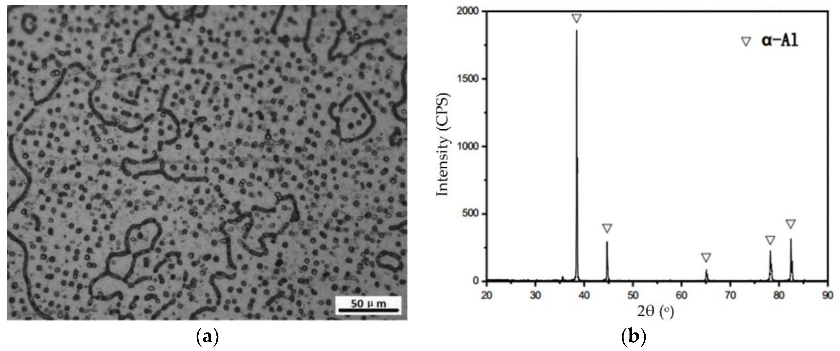
Figure 2.
Scanning electron microscopy (SEM) images of the powders: (a) CuZn40; (b) WC.

Figure 3.
Schematic diagram of the argon-shielded arc cladding process.

Figure 4.
Schematic diagram of the wear experiment.
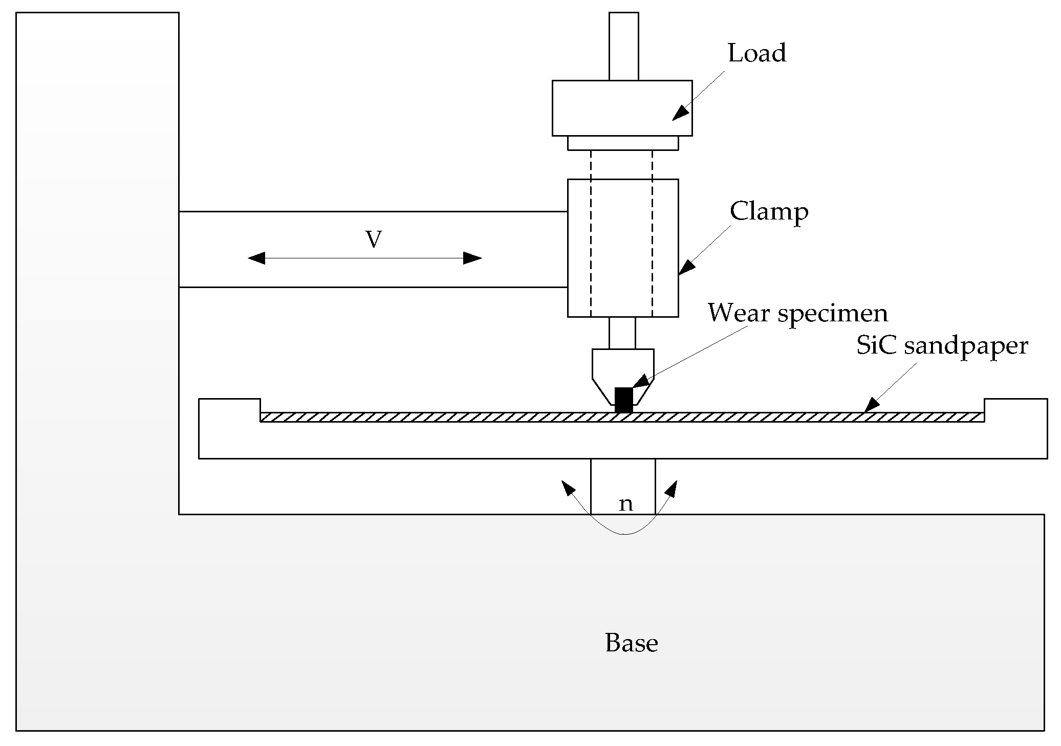
Figure 5.
Morphology of cladding layer: (a) 100 wt.% CuZn40; (b) 30 wt.% CuZn40 + 70 wt.% WC; (c) 50 wt.% CuZn40 + 50 wt.% WC; (d) 30 wt.% CuZn40 + 70 wt.% WC; (e) 20 wt.% CuZn40 + 80 wt.% WC.
Figure 5.
Morphology of cladding layer: (a) 100 wt.% CuZn40; (b) 30 wt.% CuZn40 + 70 wt.% WC; (c) 50 wt.% CuZn40 + 50 wt.% WC; (d) 30 wt.% CuZn40 + 70 wt.% WC; (e) 20 wt.% CuZn40 + 80 wt.% WC.
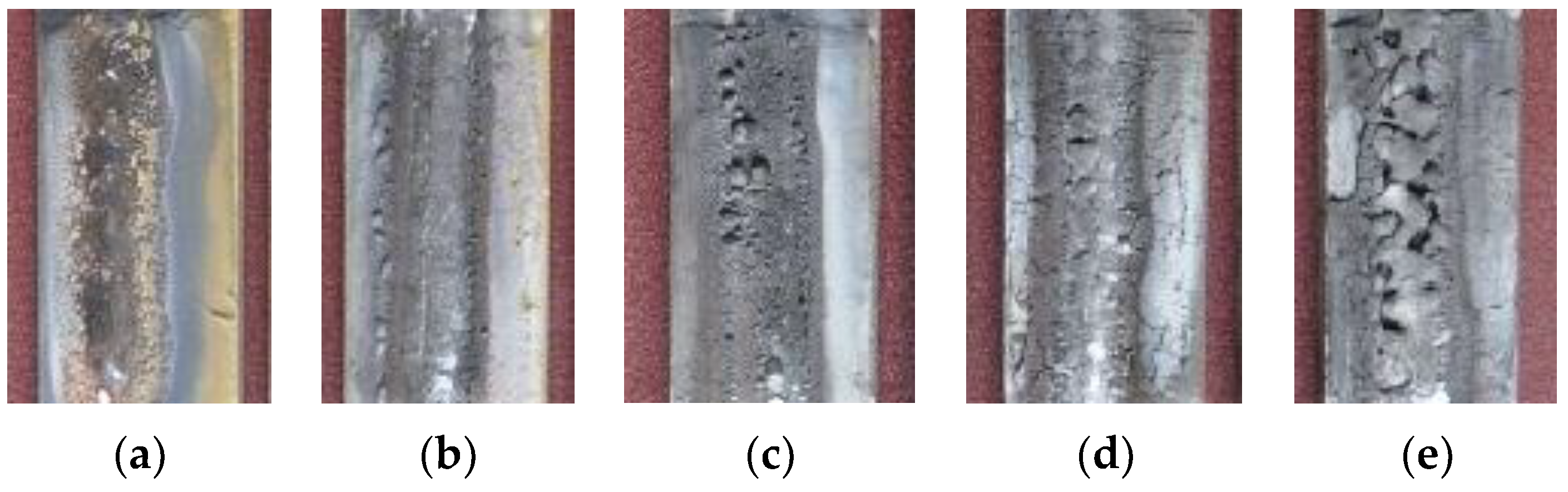
Figure 6.
Morphology of the cladding layer cross-section: (a) Typical morphology; (b) effect of WC proportion in CuZn40-WC powders on cladding layer cross-section.
Figure 6.
Morphology of the cladding layer cross-section: (a) Typical morphology; (b) effect of WC proportion in CuZn40-WC powders on cladding layer cross-section.
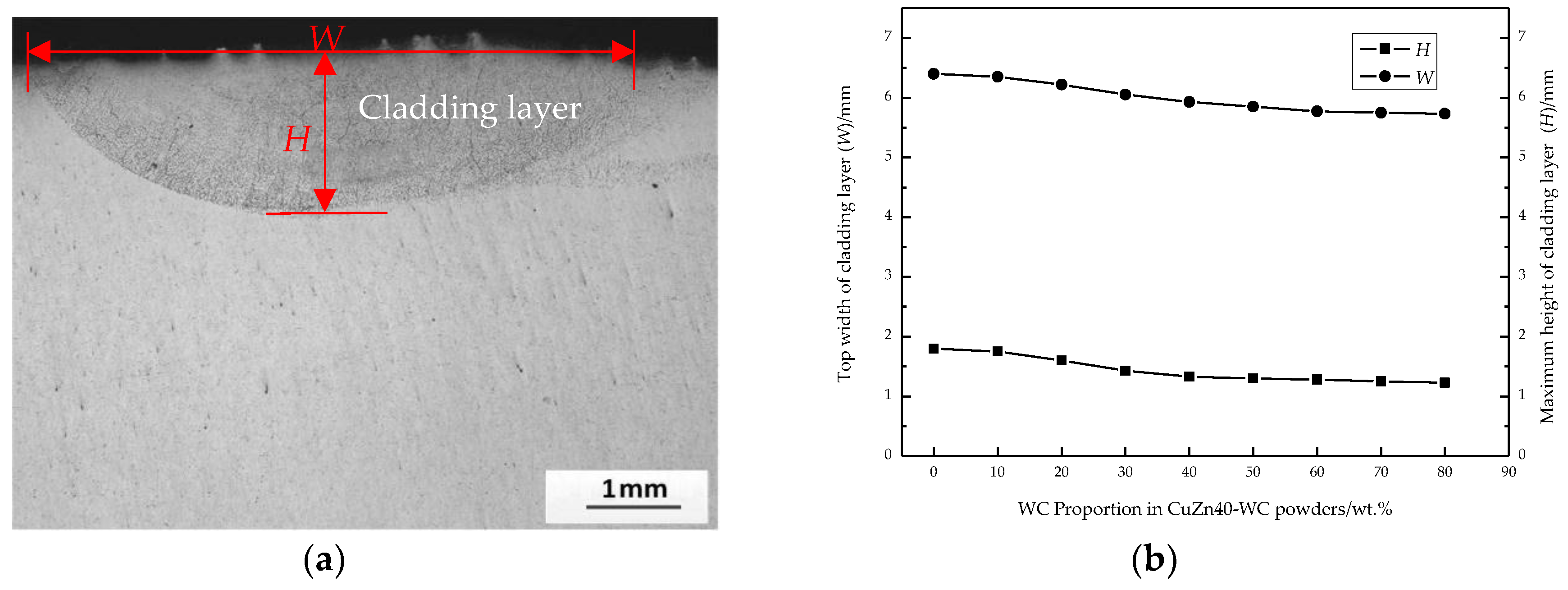
Figure 7.
Microstructure of the typical cladding layer: (a) 100 wt.% CuZn40; (b) 70 wt.% CuZn40 + 30 wt.% WC; (c) 40 wt.% CuZn40 + 60 wt.% WC; (d) 20 wt.% CuZn40 + 80 wt.% WC.
Figure 7.
Microstructure of the typical cladding layer: (a) 100 wt.% CuZn40; (b) 70 wt.% CuZn40 + 30 wt.% WC; (c) 40 wt.% CuZn40 + 60 wt.% WC; (d) 20 wt.% CuZn40 + 80 wt.% WC.

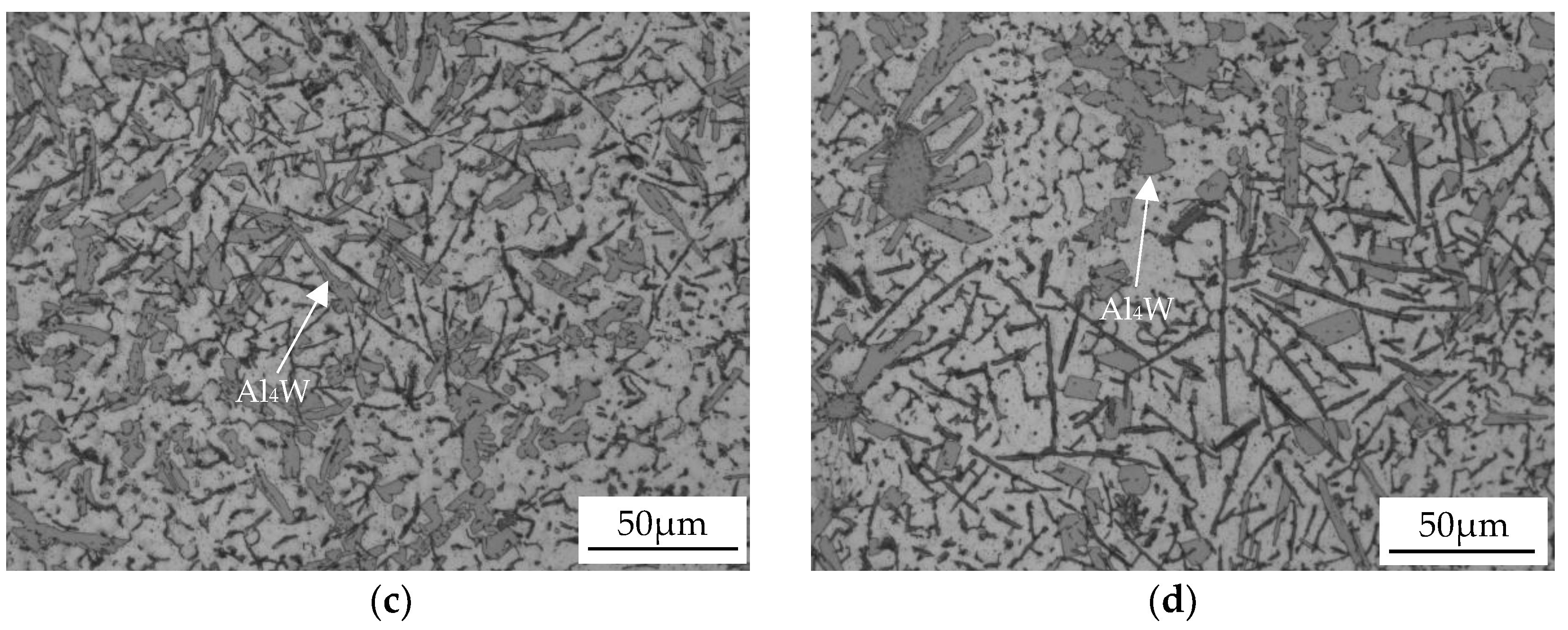
Figure 8.
Energy dispersive spectrometer (EDS) results of line scanning in the local zone of Figure 7b.
Figure 8.
Energy dispersive spectrometer (EDS) results of line scanning in the local zone of Figure 7b.
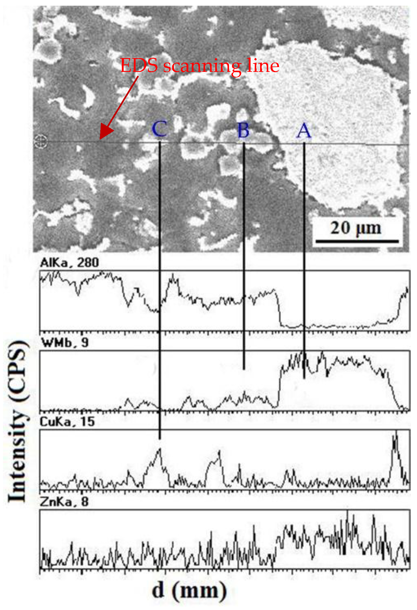
Figure 9.
XRD analysis results of the cladding layer prepared with 60 wt.% WC powders.
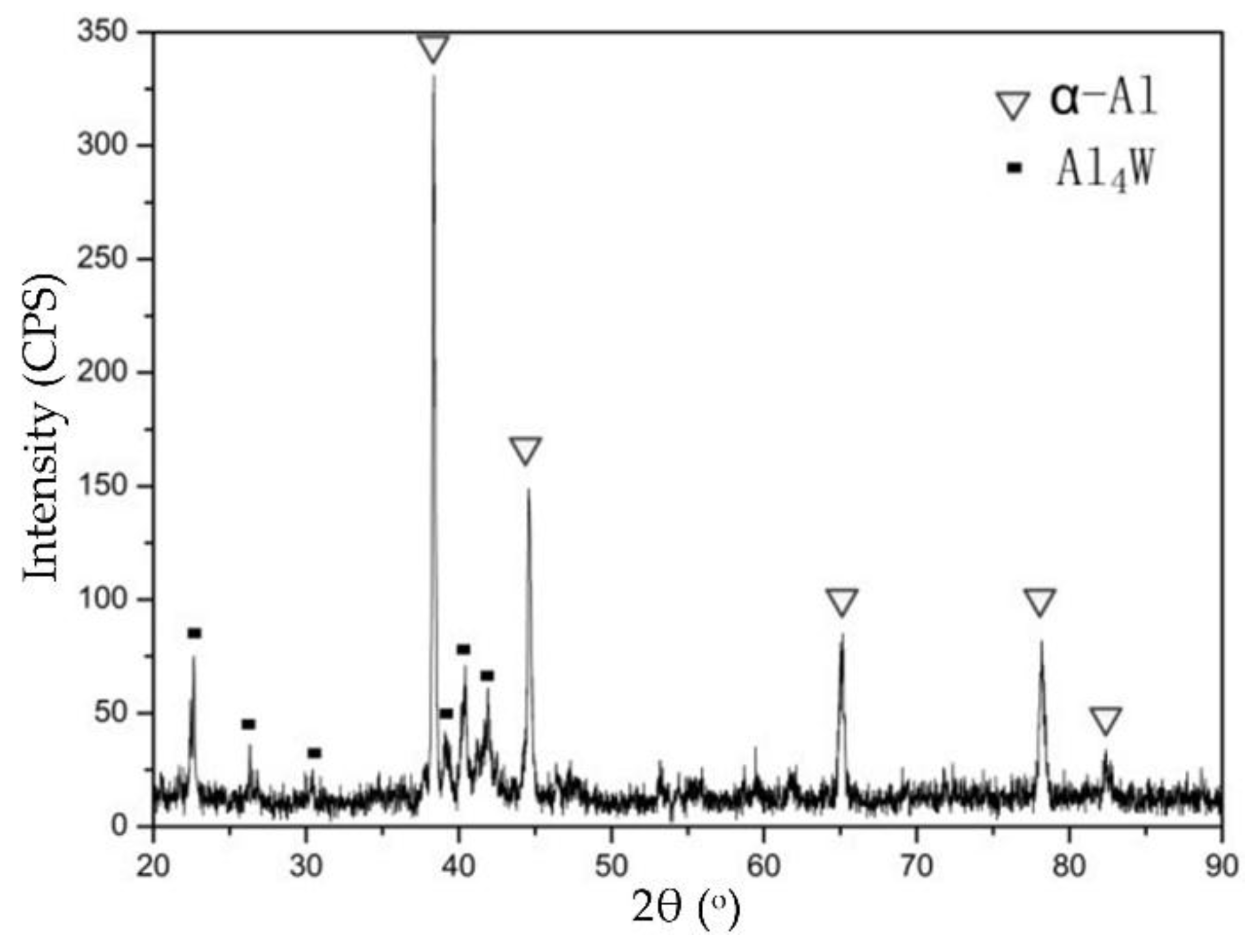
Figure 10.
(a) SEM image; (b) EDS results of the cladding layer prepared with 60 wt.% WC powders.

Figure 11.
Schematic diagram of the microhardness test.

Figure 12.
Effect of WC proportion on the average microhardness values of cladding layers.

Figure 13.
Weight loss of the Al substrate and different cladding layers.
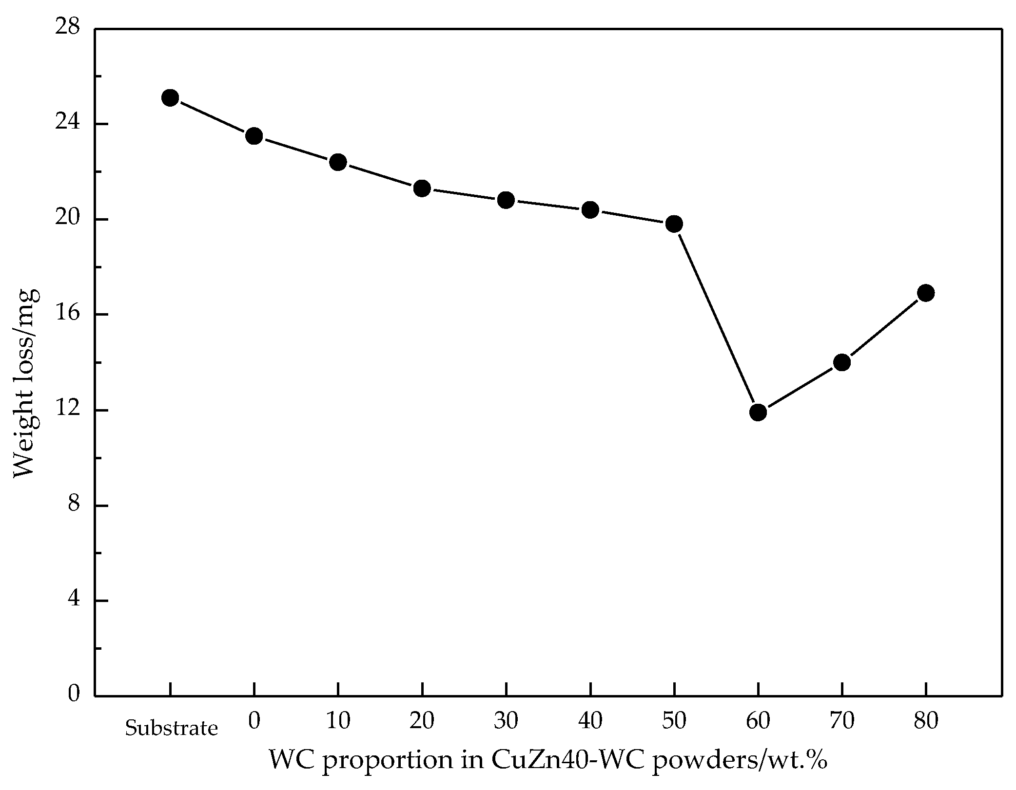
Figure 14.
Wear morphology of the aluminum substrate and cladding layers prepared with different powders: (a) Substrate; (b) 60 wt.% CuZn40 + 40 wt.% WC; (c) 40 wt.% CuZn40 + 60 wt.% WC; (d) 20 wt.% CuZn40 + 80 wt.% WC.
Figure 14.
Wear morphology of the aluminum substrate and cladding layers prepared with different powders: (a) Substrate; (b) 60 wt.% CuZn40 + 40 wt.% WC; (c) 40 wt.% CuZn40 + 60 wt.% WC; (d) 20 wt.% CuZn40 + 80 wt.% WC.


Table 1.
Main parameters of the argon-shielded arc cladding process.
| Electrode Diameter (mm) | Cladding Current (A) | Cladding Velocity (mm/s) | Flowing Velocity of Argon (L/min) |
|---|---|---|---|
| 2.4 | 160 | 2.8 | 10 |
Table 2.
The EDS results of particle I and particle II.
| Element (at.%) | Particle I | Particle II |
|---|---|---|
| Al | 76.43 | 78.59 |
| W | 21.62 | 20.35 |
| Cu | 0.83 | 0.26 |
| Zn | 1.12 | 0. 77 |
© 2018 by the authors. Licensee MDPI, Basel, Switzerland. This article is an open access article distributed under the terms and conditions of the Creative Commons Attribution (CC BY) license (http://creativecommons.org/licenses/by/4.0/).
Share and Cite
MDPI and ACS Style
Zhang, X.; Sang, Q.; Ren, Z.; Li, G. Microstructure and Properties of Cladding Layers Prepared by Argon-Shielded Arc Cladding of CuZn40-WC Powders on Pure Aluminum Substrate. Coatings 2018, 8, 382. https://doi.org/10.3390/coatings8110382
AMA Style
Zhang X, Sang Q, Ren Z, Li G. Microstructure and Properties of Cladding Layers Prepared by Argon-Shielded Arc Cladding of CuZn40-WC Powders on Pure Aluminum Substrate. Coatings. 2018; 8(11):382. https://doi.org/10.3390/coatings8110382
Chicago/Turabian StyleZhang, Xinge, Qing Sang, Zhenan Ren, and Guofa Li. 2018. "Microstructure and Properties of Cladding Layers Prepared by Argon-Shielded Arc Cladding of CuZn40-WC Powders on Pure Aluminum Substrate" Coatings 8, no. 11: 382. https://doi.org/10.3390/coatings8110382
Note that from the first issue of 2016, this journal uses article numbers instead of page numbers. See further details here.