
Computer Simulation of Temperature Parameter for Diamond Formation by Using Hot-Filament Chemical Vapor Deposition


 , and
, and
Abstract
:1. Introduction
2. Numerical and Experimental Details
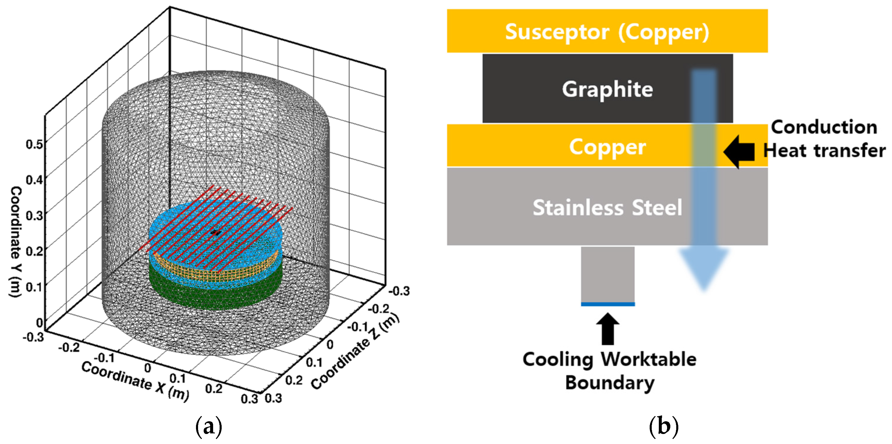
2.1. Numerical Calculation Method
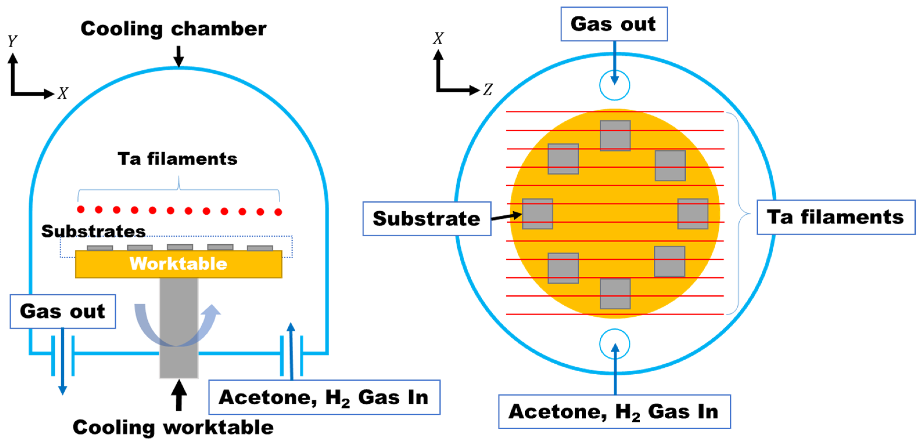
2.2. Experimental Work Using HF-CVD
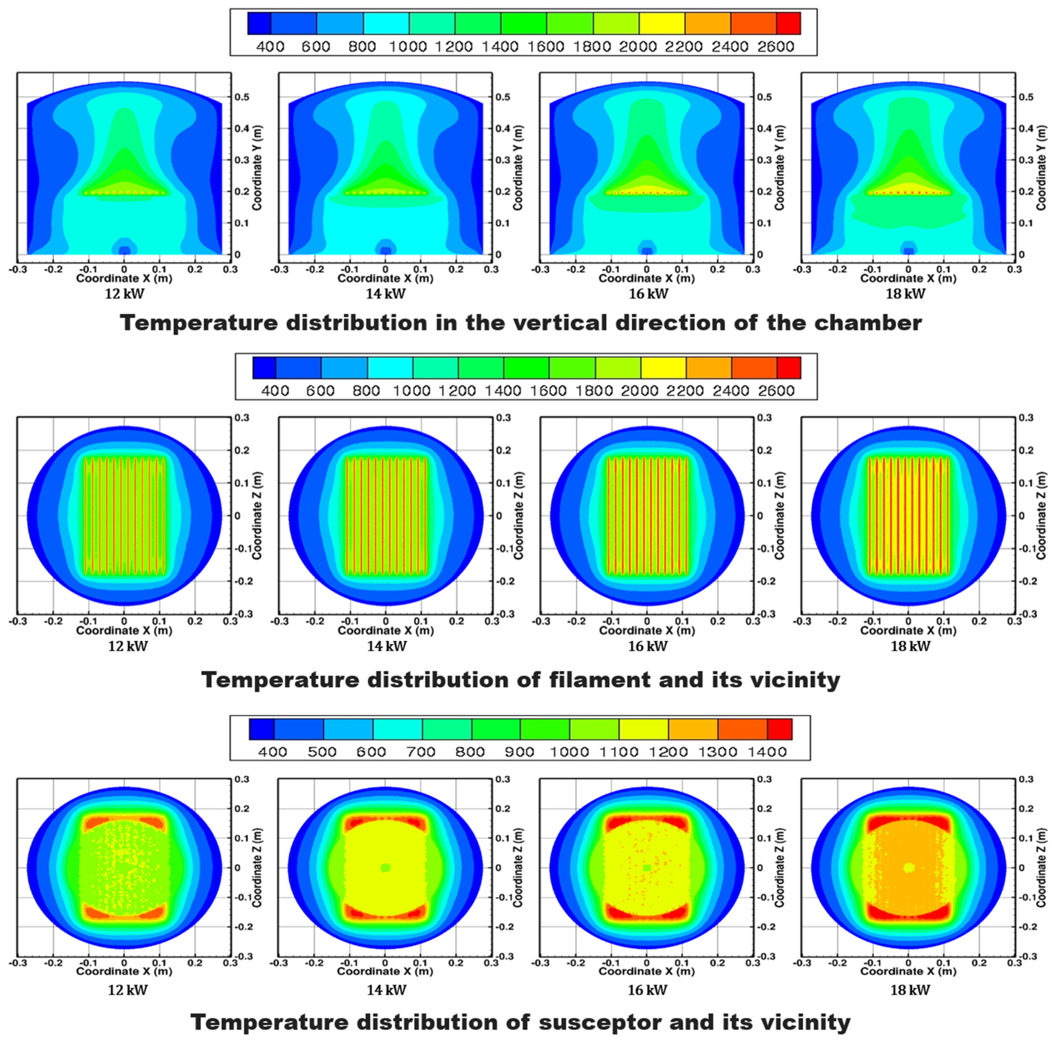
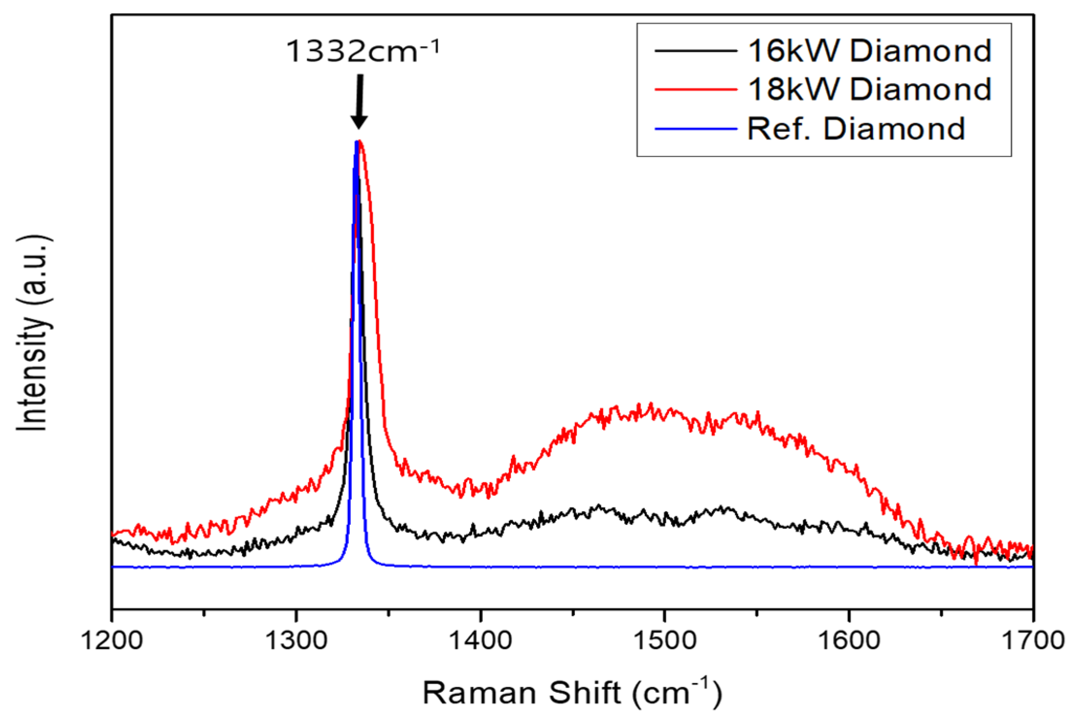
3. Results and Discussion
4. Conclusions
Acknowledgments
Author Contributions
Conflicts of Interest
References
- Abbasi, S.A.; Feng, P.F.; Ma, Y.; Zhang, J.F.; Yu, D.W.; Wu, Z.J. Influence of microstructure and hardness on machinability of heat-treated titanium alloy Ti-6Al-4V in end milling with polycrystalline diamond tools. Int. J. Adv. Manuf. Technol. 2016, 86, 1393–1405. [Google Scholar] [CrossRef]
- Meixner, M.; Klaus, M.; Genzel, C.; Reimers, W. Residual stress analysis of diamond-coated WC-Co cutting tools: Separation of film and substrate information by grazing X-ray diffraction. J. Appl. Crystallogr. 2013, 46, 1323–1330. [Google Scholar] [CrossRef]
- Ye, F.; Li, Y.S.; Sun, X.Y.; Yang, Q.Q.; Kim, C.Y.; Odeshi, A.G. CVD diamond coating on WC-Co substrate with Al-based interlayer. Surf. Coat. Technol. 2016, 308, 121–127. [Google Scholar] [CrossRef]
- Din, S.H.; Shah, M.A.; Sheikh, N.A.; Najar, K.A.; Ramasubramanian, K.; Balaji, S.; Rao, M.S.R. Influence of boron doping on mechanical and tribological properties in multilayer CVD-diamond coating systems. Bull. Mater. Sci. 2016, 39, 1753–1761. [Google Scholar] [CrossRef]
- Liu, J.; Hei, L.F.; Chen, G.C.; Li, C.M.; Song, J.H.; Lu, F.X. Mechanical properties of ultrananocrystalline diamond films modified by hydrogen concentration in deposition atmosphere. Surf. Coat. Technol. 2013, 236, 8–12. [Google Scholar] [CrossRef]
- May, P.W.; Ashfold, M.N.R.; Mankelevich, Y.A. Microcrystalline, nanocrystalline, and ultrananocrystalline diamond chemical vapor deposition: Experiment and modeling of the factors controlling growth rate, nucleation, and crystal size. J. Appl. Phys. 2007, 101, 053115. [Google Scholar] [CrossRef]
- Cristofanilli, G.; Polini, R.; Barletta, M. HF-CVD of diamond coatings onto Fluidized Bed (FB) treated CrN interlayers. Thin Solid Films 2010, 519, 1594–1599. [Google Scholar] [CrossRef]
- Sumant, A.V.; Dharmadhikari, C.V.; Godbole, V.P. Some investigations on HF-CVD diamond using scanning tunneling microscopy. Mater. Sci. Eng. B 1996, 41, 267–272. [Google Scholar] [CrossRef]
- Kukushkin, V.A. Simulation of a perfect CVD diamond Schottky diode steep forward current-voltage characteristic. Phys. B Condens. Matter 2016, 498, 1–6. [Google Scholar] [CrossRef]
- Kukushkin, V.A.; Bogdanov, S.A. Simulation of CVD diamond-based high speed near-infrared photodetectors. Diam. Relat. Mater. 2015, 60, 94–98. [Google Scholar] [CrossRef]
- Van Veldhuizen, S.; Vuik, C.; Kleijn, C.R. Comparison of numerical methods for transient CVD simulations. Surf. Coat. Technol. 2007, 201, 8859–8862. [Google Scholar] [CrossRef]
- Song, G.H.; Sun, C.; Huang, R.F.; Wen, L.S.; Shi, C.X. Heat transfer simulation of HFCVD and fundamentals of diamond vapor growth reactor designing. Surf. Coat. Technol. 2000, 131, 500–505. [Google Scholar] [CrossRef]
- Eckstein, B.H.; Forman, R. Preparation and some properties of tantalum carbide. J. Appl. Phys. 1962, 33, 82–87. [Google Scholar] [CrossRef]
- Sarangi, S.K.; Chattopadhyay, A.; Chattopadhyay, A.K. Effect of pretreatment, seeding and interlayer on nucleation and growth of HFCVD diamond films on cemented carbide tools. Int. J. Refract. Met. Hard Mater. 2008, 26, 220–231. [Google Scholar] [CrossRef]
- Bareiss, J.C.; Hackl, G.; Popovska, N.; Rosiwal, S.M.; Singer, R.F. CVD diamond coating of steel on a CVD-TiBN interlayer. Surf. Coat. Technol. 2006, 201, 718–723. [Google Scholar]
- Katamune, Y.; Mori, H.; Izumi, A. Growth of diamond thin films on SiCN underlayers by hot filament chemical vapor deposition. Thin Solid Films 2017, 635, 53–57. [Google Scholar] [CrossRef]
- Zhou, H.X.; Yuan, B.Y.; Lyu, J.L.; Jiang, N. A novel approach of deposition for uniform diamond films on circular saw blades. Plasma Sci. Technol. 2017, 19, 115502. [Google Scholar] [CrossRef]
- Chen, Z.C.; Subhash, G.; Tulenko, J.S. Raman spectroscopic investigation of graphitization of diamond during spark plasma sintering of UO2-diamond composite nuclear fuel. J. Nucl. Mater. 2016, 475, 1–5. [Google Scholar] [CrossRef]
- De Feudis, M.; Caricato, A.P.; Taurino, A.; Ossi, P.M.; Castiglioni, C.; Brambilla, L.; Maruccio, G.; Monteduro, A.G.; Broitman, E.; Chiodini, G.; et al. Diamond graphitization by laser-writing for all-carbon detector applications. Diam. Relat. Mater. 2017, 75, 25–33. [Google Scholar] [CrossRef]
- Uzansaguy, C.; Cytermann, C.; Brener, R.; Richter, V.; Shaanan, M.; Kalish, R. Damage threshold for ion-beam-induced graphitization of diamond. Appl. Phys. Lett. 1995, 67, 1194–1196. [Google Scholar] [CrossRef]
- Shakhov, F.M.; Abyzov, A.M.; Kidalov, S.V.; Krasilin, A.A.; Lahderanta, E.; Lebedev, V.T.; Shamshur, D.V.; Takai, K. Boron-doped diamond synthesized at high-pressure and high-temperature with metal catalyst. J. Phys. Chem. Solids 2017, 103, 224–237. [Google Scholar] [CrossRef]
- Battaile, C.C.; Srolovitz, D.J.; Oleinik, I.I.; Pettifor, D.G.; Sutton, A.P.; Harris, S.J.; Butler, J.E. Etching effects during the chemical vapor deposition of (100) diamond. J. Chem. Phys. 1999, 111, 4291–4299. [Google Scholar] [CrossRef]
- Kuzmany, H.; Pfeiffer, R.; Salk, N.; Gunther, B. The mystery of the 1140 cm−1 Raman line in nanocrystalline diamond films. Carbon 2004, 42, 911–917. [Google Scholar] [CrossRef]


| Parameter | Value |
|---|---|
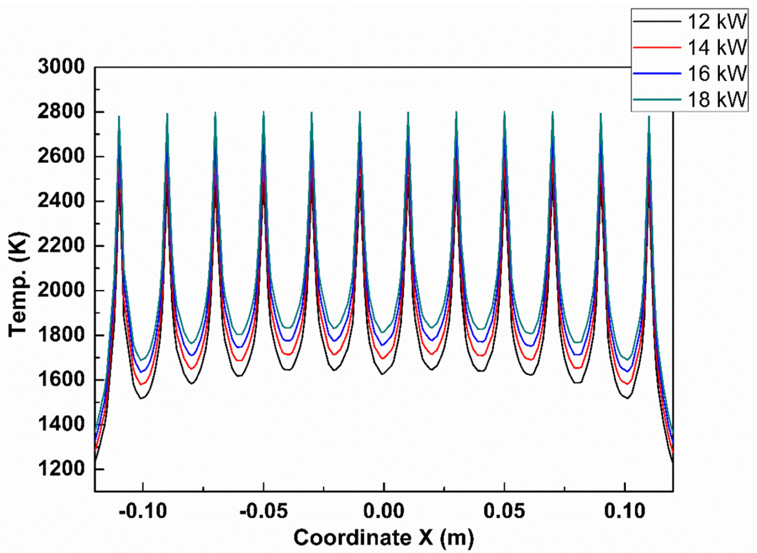
| Filament power (kW) | 12, 14, 16, and 18 |
| Number of filaments | 12 |
| Length of each filament (cm) | 32 |
| Pressure (Pa) | 4000 |
| Flux of the hydrogen (sccm) | 400 |
| Flux of the Cn (sccm) | 90 |
| Gas ratio (Acetone/H2) | 0.017 |
| Distance between filament and susceptor (mm) | 10 |
| Distance between filaments (mm) | 20 |
| Deposition time (h) | 8 |
| Filament Power (kW) | Calculated Filament Temperature (K) | Measured Filament Temperature (K) |
|---|---|---|
| 12 | 2512 | 2504 |
| 14 | 2619 | 2632 |
| 16 | 2715 | 2711 |
| 18 | 2802 | 2858 |
| Filament Power (kW) | Calculated Susceptor Temperature (K) |
|---|---|
| 12 | 1076 |
| 14 | 1121 |
| 16 | 1161 |
| 18 | 1198 |
© 2017 by the authors. Licensee MDPI, Basel, Switzerland. This article is an open access article distributed under the terms and conditions of the Creative Commons Attribution (CC BY) license (http://creativecommons.org/licenses/by/4.0/).
Share and Cite
Song, C.W.; Lee, Y.H.; Heo, S.Y.; Hwang, N.-M.; Choi, S.; Kim, K.H. Computer Simulation of Temperature Parameter for Diamond Formation by Using Hot-Filament Chemical Vapor Deposition. Coatings 2018, 8, 15. https://doi.org/10.3390/coatings8010015
Song CW, Lee YH, Heo SY, Hwang N-M, Choi S, Kim KH. Computer Simulation of Temperature Parameter for Diamond Formation by Using Hot-Filament Chemical Vapor Deposition. Coatings. 2018; 8(1):15. https://doi.org/10.3390/coatings8010015
Chicago/Turabian StyleSong, Chang Weon, Yong Hee Lee, Si Young Heo, Nong-Moon Hwang, Sooseok Choi, and Kwang Ho Kim. 2018. "Computer Simulation of Temperature Parameter for Diamond Formation by Using Hot-Filament Chemical Vapor Deposition" Coatings 8, no. 1: 15. https://doi.org/10.3390/coatings8010015
APA StyleSong, C. W., Lee, Y. H., Heo, S. Y., Hwang, N.-M., Choi, S., & Kim, K. H. (2018). Computer Simulation of Temperature Parameter for Diamond Formation by Using Hot-Filament Chemical Vapor Deposition. Coatings, 8(1), 15. https://doi.org/10.3390/coatings8010015