Article

Microstructure, Mechanical, Oxidation and Corrosion Properties of the Cr-Al-Si-N Coatings Deposited by a Hybrid Sputtering System

1
School of Convergence Science, Pusan National University, Busan 609-735, Korea
2
Global Frontier R&D Center for Hybrid Interface Materials, Pusan National University, Busan 609-735, Korea
3
National Core Research Center for Hybrid Materials Solution, Pusan National University, Busan 609-735, Korea
4
School of Electromechanical Engineering, Guangdong University of Technology, Guangzhou 510006, China
*
Authors to whom correspondence should be addressed.
Coatings 2017, 7(8), 119; https://doi.org/10.3390/coatings7080119
Submission received: 30 July 2017 / Revised: 30 July 2017 / Accepted: 7 August 2017 / Published: 9 August 2017
(This article belongs to the Special Issue Mechanical Behavior of Coatings and Engineered Surfaces)

Abstract

:
CrN and Cr-Al-Si-N coatings were deposited on SUS304 and Si-wafers by a hybrid coating system. The Cr and Al-Si target were connected to the cathode arc ion plating (AIP) and high power impulse magnetron sputtering (HiPIMS), respectively. Various Al and Si contents in the coatings were obtained by changing the power of Al-Si target from 0 to 1 kW. The results demonstrated a face-centered cubic structure in all of the coatings. With increasing Al-Si target power, both the density and mean diameter of the macroparticles on the coating surface declined. As Al and Si contents increased, the microstructure of the Cr-Al-Si-N coatings evolved from a dense column structure, to a finer grain column structure, and then to a compact granular-like structure. The hardness of the coatings increased from 21.5 GPa for the pure CrN coating, to a maximum value of ~27 GPa for the Cr-Al-Si-N coating deposited at 0.4 kW, which was mainly attributed to the solid solution strengthening and increased residual stress. The addition of Al and Si contents led to enhanced wear resistance against alumina balls at both room and elevated temperatures. Meanwhile, the Cr-Al-Si-N coatings also exhibited an excellent resistance to high-temperature oxidation at 800 and 1000 °C, and improved corrosion resistance, as compared with CrN coatings.

1. Introduction

Transition metal nitride coatings, especially CrN-based coatings, have been widely studied as protective materials for various cutting tools and high-temperature applications in last two decades due to their relatively high hardness, good tribological properties, good thermal stability, and oxidation resistance [1,2,3,4,5,6,7,8]. The performance of such coatings can be further improved by doping a third metal or nonmetal element into the CrN-based coatings, such as Al [3,9], Mo [10], Zr [11], Cu [12], C [13], Si [14] and Al-Si [15,16] elements. These elements have all been previously used to modify the structures and properties of the CrN coatings. Among them, Cr-Al-N films, compared with CrN coatings, show better comprehensive properties, such as higher hardness and improved thermal stability. Particularly, Cr-Al-N films have superior oxidation resistance up to 900 °C due to the formation of a dense and thermally stable Cr2O3-Al2O3 oxide layer through the movement of Al and Cr atoms over the film surface region. The barrier of the oxide layer prevents further outward diffusion of Cr and N elements and also inward diffusion of oxygen into the film, which deteriorates the film structure [17,18,19,20,21].
Cr-Si-N is another promising CrN-based coating. With a proper Si doping concentration, one can obtain a denser structure, which consists of nano-sized CrN crystals embedded in a thin amorphous Si3N4 phase tissue. In Zou’s work [22], which added a Si content of 2.1–11.1 at.% into CrN coating, friction coefficients decreased and the maximum hardness of 2490 HV was achieved at a Si content of 6.94 at.% due to the formation of a nanocomposite structure. It is inferred that quaternary Cr-Al-Si-N coatings exhibit the superior hybrid properties of super hardness and excellent oxidation resistance if the quaternary film microstructure was properly modified by Al-Si doping. However, relative few research studies have been carried out that analyze the impact of extreme environments on Cr-Al-Si-N coatings, especially on their high-temperature oxidation and tribological properties, and corrosion properties in simulated marine environments [23,24,25].
In this work, the Cr-Al-Si-N coatings were prepared by a hybrid coating system that combined high power impulse magnetron sputtering (HiPIMS) on an Al-Si target, and arc ion plating (AIP) on a Cr target. The Cr-Al-Si-N coatings with various Al and Si contents were obtained by changing the Al-Si target power. The influence of Al and Si additions on the microstructure, mechanical properties, high-temperature oxidation and tribological performance, and corrosion resistance of the fabricated Cr-Al-Si-N coatings were systematically studied.

2. Experimental Details

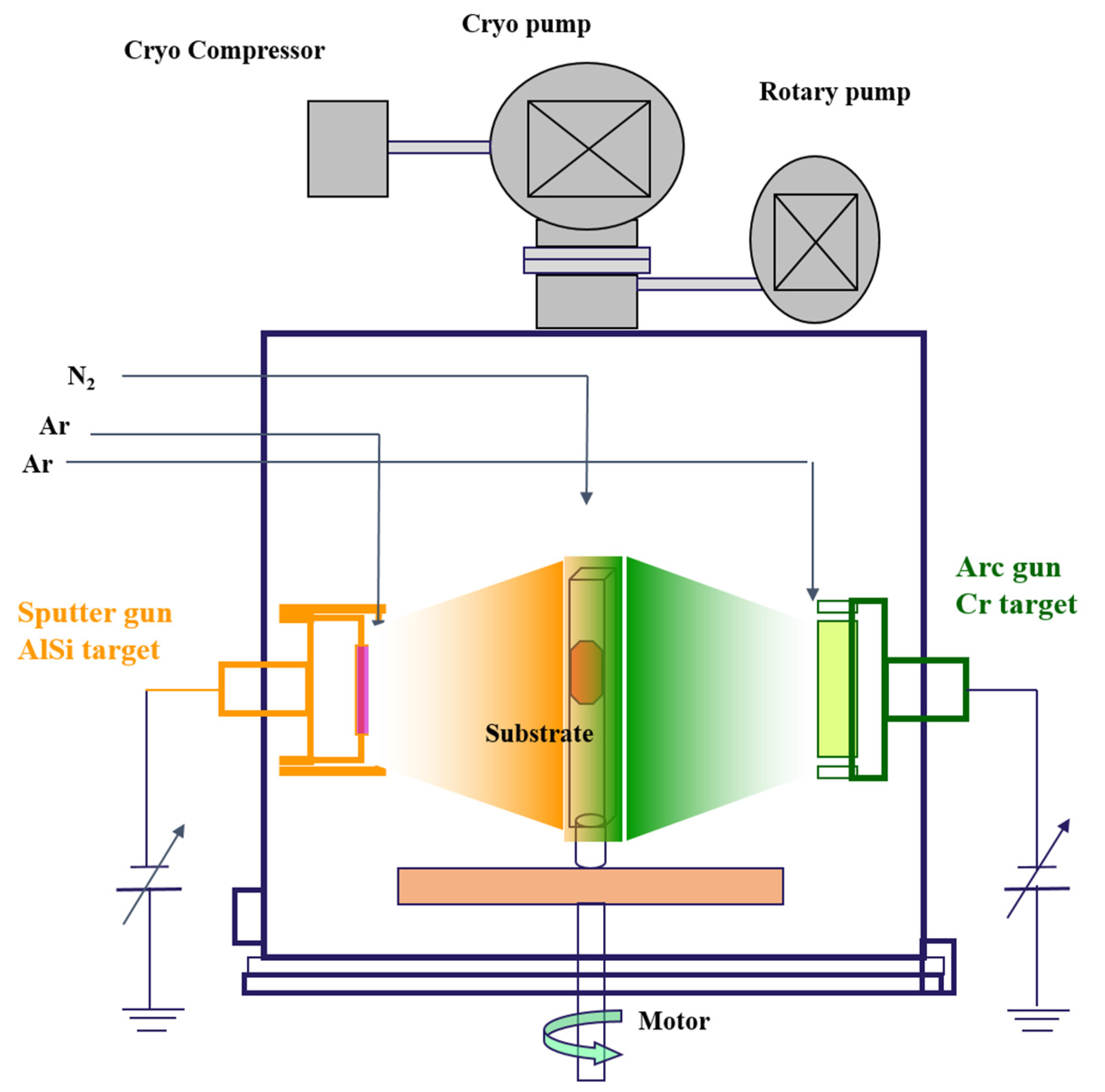
2.1. Film Deposition

The Cr-Al-Si-N films were deposited on single-crystalline Si (100) wafers (for EPMA, SEM, XRD, XPS, AFM, hardness, residual stress analysis and oxidation tests) and mirror-polished SUS 304 stainless steel substrates (for friction and corrosion tests) using a hybrid coating system, which consisted of an AIP and a HiPIMS source. A pure CrN coating was also fabricated for comparison. Figure 1 shows the schematic diagram of the hybrid coating system. The HiPIMS sputter gun for the Al-Si source, and arc cathode gun for the Cr source, were installed on opposite sides of the vacuum chamber. A rotational substrate holder was located on a straight line between the two sources, with the distances of 350 and 250 mm from the arc and sputter source to the substrate holder, respectively. An extra bias supply was connected to the sample holder. All of the substrates were cleaned by an ultrasonic cleaner bath using acetone and alcohol solution for 15 min. These clean samples were dried by nitrogen gas and then fixed on the holder. In order to increase the sputtering rate and reduce the poisoning of the target during the deposition procedure, argon gas (99.999%) was injected into the surroundings of the Cr and Al-Si targets, respectively, with a total gas flow of 50 Sccm, and nitrogen gas was introduced near the substrate holder. The base pressure was evacuated to below 6.5 × 10⁻³ Pa, and the working pressure was maintained at 0.8 Pa through adjusting the throttle value behind the chamber. Prior to deposition, ion bombardment was conducted by Ar glow discharge for 10 min with a DC bias of −800 V at 0.8 Pa. Then, plasma etching was also processed by the AIP with the Cr target at a DC bias of −800 V for 5 min. To improve the adhesion between the substrate and films, a Cr interlayer was deposited for 5 min. The HiPIMS power varied from 0 to 1 KW for obtaining Al-Si-doped coatings. The deposition time was 90 min, except for the CrN coating (120 min), and the deposition temperature was fixed at 300 °C. The substrate holder rotated continuously at 10 rpm during the deposition process, which resulted in a uniform texture film on the substrates. The DC bias voltage was also kept at −100 V, and no apparent microarcs occurred, which would deteriorate the film structure. The detailed parameters used for the preparation of the CrN and Cr-Al-Si-N coatings were summarized in Table 1.

2.2. Film Characterizations

The thicknesses of CrN and the various Cr-Al-Si-N coatings were measured from the cross-sections of field emission-scanning electron microscopy images (FE-SEM, S4800, Hitach, Tokyo, Japan) coupled with an energy dispersive X-ray spectroscope (EDS, Oxford ISIS, Oxford, UK), and deposition rates were calculated according to the individual deposition time. The chemical composition of the films (Cr, Al, Si, N) was carried out by electron probe microanalysis (EPMA, A SX100, Camera, Paris, France). The crystallinity of the films was confirmed from the X-ray diffraction (XRD) patterns measured from a Bruker D8 Advance X-pert diffractometer system, with Kα Cu radiation (40 kV and 40 mA) within a 20°–80° diffraction angles range. The elemental chemical bonding status in the films was studied by X-ray photoelectron spectra (XPS, VG Scientifics, Shimadzu, Kyoto, Japan, ESCALAB 250), using the Ar+ ions etching sample surface for 180 s, and the spectra were calibrated for the value of carbon peak C 1 s at 284.5 eV. Macroparticle densities and the average size of sample films were obtained from the SEM-surface images by using the Image-Pro Plus software program. The surface topography and average roughness of the films were studied by an atomic force microscopy (MFM-3D, AFM, Asylum Research, Santa Barbara, CA, USA) 2D/3D images. The hardness and Young’s modulus values of the coatings were tested through using a nanoindentation tester (TI950 TriboIndentor, Hysitron, MN, USA) under a constant load of 6 mN. For obtaining the accurate experiment values, the results were collected as an average of 20 measurement readings. Residual stress values were estimated through the stress tester machine (J&L Advanced Plasma Technology™, Ansan, Korea) that applied a laser and calculated with the Stoney equation [26].
The tribological behaviors were evaluated by using a ball-on-disc tribometer (CSM, THT) with an Al2O3 ball (6 mm in diameter) as counterpart material. The wear test was conducted with a rotational speed of 400 r/min under a load of 2 N at room temperature in an ambient environment with relative humidity of 50 ± 5%, and at elevated temperature (500 °C) within 3000 cycles. The wear rates (W) of coatings were calculated according the equation: W = V/SL, where V is the wear volume loss in m3, S is the applied load in N, and the L is the total sliding distance in meters (m). Isothermal oxidation tests, deposited on Si wafers, were measured at 800 °C and 1000 °C in a muffle furnace for 1 h. The corrosion properties of the samples (SUS304 specimens coated with and without films) were conducted in a 3.5 wt % NaCl solution (simulating the natural marine environment) using a three-electrode cell configuration, which consisted of the sample as the working electrode, platinum (Pt) mesh as the counter electrode, and a saturated calomel electrode (SCE) as the reference electrode. The electrode potential range of the measurement was carried out from −1 V to 1.2 V and the SCE with a scan rate of 1 mV/s.

3. Results and Discussion

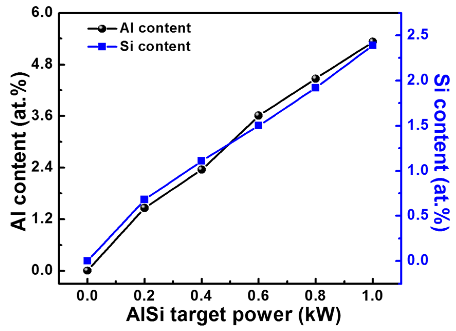
3.1. Composition and Deposition Rate

Figure 2 describes the variation of Al and Si contents in the coatings as a function of Al-Si target power. It can be seen that the Al and Si content linearly increased with the increase of target power. When higher power was applied to the target, excess material quantity sputtered from the original target and formed a film at the surface of the substrate, which led to more Al-Si content in the films [27]. Thereby, the contents in the films during the deposition process could be precisely controlled by adjusting the target power. As shown in Table 1, the deposition rate increased proportionally from 1.45 to 1.75 µm/h by increasing the target power from 0 to 1 kW. With the sputtering power increased, the plasma density of surface of the Al-Si target enhanced as the deposited atoms could achieve enough kinetic energy from high-energy ionization argon gas. Then, these atoms, carrying sufficient momentum, transferred to the surface of the substrate, and led to the formation of the nucleation and favored the growth of the films, which resulted in an enhancement of the overall thickness [28].

3.2. Morphology and Microstructure Analyses

The typical SEM surface morphology images of the Cr-Al-Si-N coatings deposited using a hybrid system under various Al-Si target powers are presented in Figure 3a–c. Three types of defects were indicated with arrows in Figure 3a, i.e., (a) macroparticles (EDX measured mainly Cr metal in the droplets), the sizes changed from several hundreds of nanometers to several micrometers; (b) shallow-craters with diameters of hundreds of nanometers or several micrometers and (c) pin-holes, whose diameter sizes varied from tens to hundreds of nanometers, were confirmed on the surfaces of films. These macroparticles came from droplets that were emitted from the arc spots of the Cr target. Generally, based on the existence form on the surface of the coatings, the macroparticle can divide into two types: Solid droplets and liquid droplets. Wang et al. [29] reported that the droplets generated by an arc ion platting were in either a solidified or liquid state on the surface of films. According to their statement, the macroparticles on the film could be obtained on solidification of the droplets at a low-bias voltage; nevertheless, those were mostly liquid droplets at high-bias voltage. In this work, most of the droplets were in a solid state when they arrived at the substrate as defects in the film. Due to the over 200 mm distance from the target to the substrate, the macroparticles lost heat rapidly during the flight to the substrate, and kept a solid state before arriving at the substrate. There was also a few liquid droplets, according to the evidence of droplet shrinking on the film. The observed pinholes were usually shallow, and not throughout the film. That was because of the detachment of large droplets during initial film growth, which were subsequently covered by newly deposited film. According to Zhang’s report [30], three factors can explain the formation of shallow craters. One factor is that solid droplets flaked off from the film surface during the high-energy ion bombardment and etching. A second factor is that liquid droplets shrank on the film due to rapidly heating and cooling during the process. The last factor is that solid droplets bombarded into liquid droplets. To make a quantitative analysis, we selected macroparticles with a diameter size of over 0.25 µm for counting. Figure 3d, which used the Image-Pro Plus software program calculation, shows that the macroparticle densities and diameter sizes decreased largely from 0.231 p/µm2 to 0.108 p/µm2 and 0.57 µm to 0.42 µm, respectively, with increasing Al-Si target power. There are two explanations for these phenomena. One significant reason is that using the advanced HiPIMS technique can produce high-density plasma with increasing input power during the deposition process [31]. The sputtered ions could carry high amounts of energy from the plasma bombard into the surface of the film, and the loosely adhered macroparticles fell off the film [26,32]. The second reason is that the Cr concentration decreased in the film. With the increase of Al-Si power, the Cr concentration reduced as the Al and Si concentrations in the film increased. Since the macroparticles were mainly composed of Cr atoms, the amount and diameter size of the macroparticles would decrease along with decreasing Cr concentration.
Figure 4a–c exhibits the cross-sectional FE-SEM images of samples containing various Al-Si target powers. An interlayer Cr layer can be clearly seen in all of the films, which adhered well to the Cr layer. It can be seen that a pronounced columnar structure was nearly throughout the film thickness for the Al-Si-free film. Neither voids nor pinholes were seen in the whole columnar structures, which confirmed that the pinholes on the surface of the film did not penetrate deeply into the film. As the Al-Si target power increased, the width of the columnar grains decreased gradually and the structure became more impacted, as showed in Figure 4b. Also, the structure growth transferred from a continuous columnar to a discontinuous columnar, as evidenced when the Al and Si content increased from 0 at.% to 2.35 at.% and 1.11 at.%, respectively. With further increasing Al-Si target power, the structure changed to full dense glassy features and the columnar structure topography disappeared (Figure 4c). This result is similar to other reports [2,22]. A certain amount of Si could form an amorphous phase encapsulating the crystalline grain as well as restraining the grain growth. Therefore, crystalline size also decreases with Si incorporation [33,34]. At higher sputtering power, the adatoms’ mobility and diffusivity were also greatly enhanced, which resulted in the densification of the film. All of the above contributed to the denser and featureless microstructure.
From Figure 3a–c, it is clear that not only did the number of macroparticles and density vary, the topographies were changing, too. To investigate the surface topographies on the film more clearly, a series of Cr-Al-Si-N films were scanned for AFM three-dimensional images with various Al-Si target power. Figure 5a–c shows the typical AFM images. Several high and coarse cone-shaped columnar structures are extrusive in the AlSi-free coating. However, with Al-Si target power increasing, the heights of the extrusive tops were greatly reduced. When the Al-Si target power increased up to 1 kW, the cone columnar structure nearly disappeared. In Huang’s and Zou’s work [22,33], it was found that the addition of Si into the film had a significant influence on its microstructure, which became finer in grain size and more randomly oriented in crystallographic direction. These findings are also confirmed by the SEM cross-section images and XRD results discussed later in this work. Figure 5d presents the results of root-mean-square (RMS) roughness under different Al-Si powers. The RMS roughness value of the Al-Si-free coating was higher. By doping Al-Si concentration, the roughness values of the films greatly reduced. The minimum roughness in the films was obtained at the value of 0.8 kW, then rebounded in a small increments at 1 kW. The surface roughness of the coatings is also related to crystalline size and the orientation of crystallites [35]. It was also affected by enhanced Al-Si target power. When the mobility of the incident ions on the surface of films increased, which promoted the formation of a dense film, there was a documented decrease of surface roughness. The rebounding phenomenon of the roughness in the film at the value of 1 kW was ascribed to the recrystallization and ion-bombardment effects at higher power sputtering.

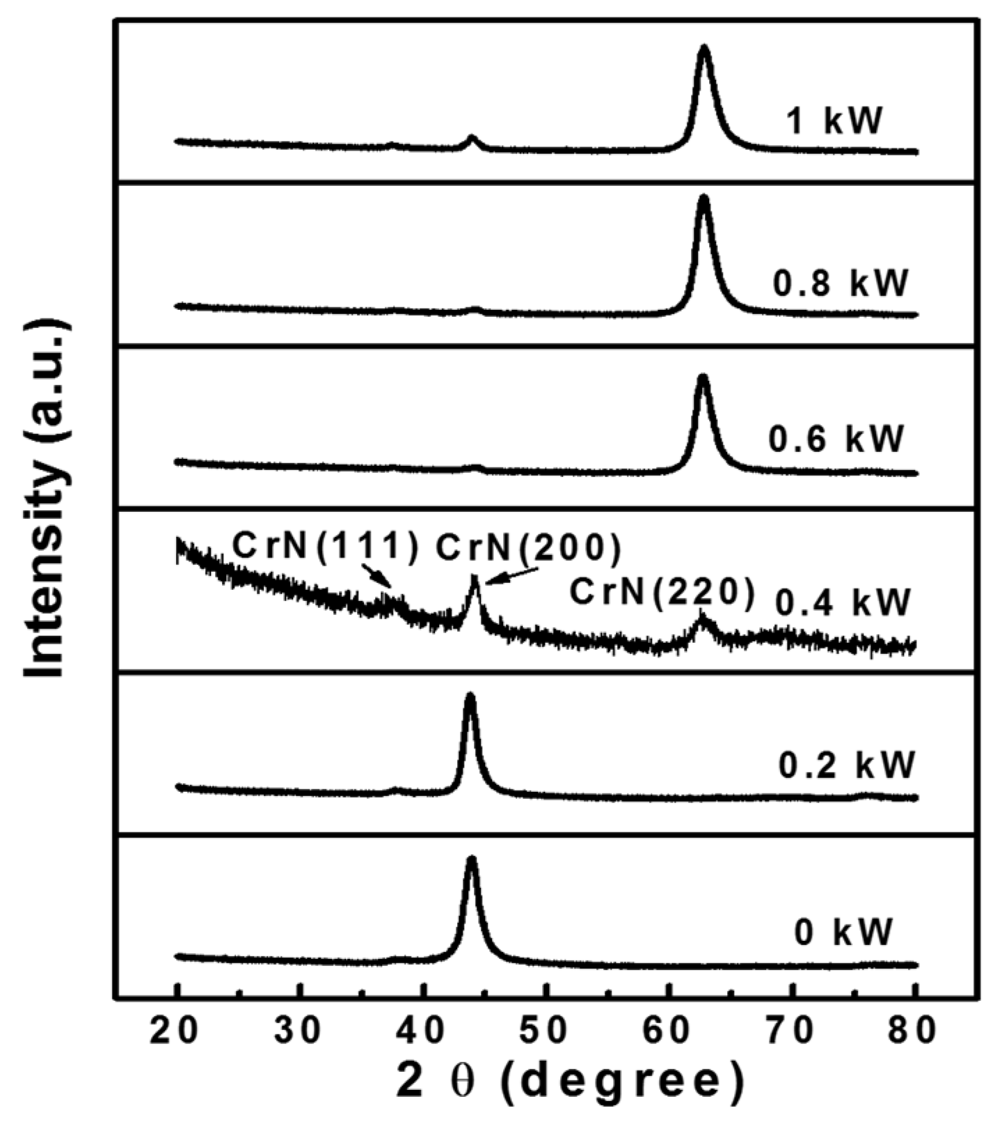
3.3. XRD and XPS Analysis

Figure 6 exhibits the XRD patterns of the Cr-Al-Si-N coatings deposited with various Al-Si powers by a hybrid coating system. The XRD pattern of CrN film was also tested for comparison. All of the films demonstrated crystalline face-centered NaCl-type cubic structures with different preferred orientations. The preferred growth direction of Al-Si-free CrN coating is the (200) plane. When the Al-Si target power was up to 0.4 kW, the peak intensity of the (200) crystal plane decreased rapidly, and showed a mixture of (111), (200), and (220) crystalline planes. With further increases of Al-Si power, the crystallographic orientation changed from (200) to (220). The deflection point occurred at the power of 0.4 kW. It is worthy to note that the diffraction angles in this work were all negatively deviated compare with the standard CrN phase according the Joint Committee For Powder Diffraction Studies (JCPDS) card (PDF#110065) result, in which 37.61°, 43.78° and 63.6° corresponding to the (111), (200), and (220) growth planes, respectively. This implies that compress stress exists in the films, which is supported by the measurement of the stress results in Section 3.4. No other crystal peaks signals such as Cr, Cr2N, CrSi2 and Si3N4 were detected. This result postulated that Si existed as either substitution solid solution in the Cr-Al-N lattice or amorphous Si-N compound accumulated at the Cr-Al-N grain boundaries [34,36]. We divided the Al-Si target power into two different zones, as seen in Figure 6. The first zone is the Al-Si target power from 0 to 0.4 kW, and the second zone is from 0.6 to 1 kW. In the first zone, a small amount of Al-Si was added into the film, which resulted in a slight broadening of (200) diffraction peaks and a shift towards the lower 2θ angle. This meant that the compress stress increased with a little addition of Al-Si content in this zone. As the Al-Si target increased, two apparent characteristics in the second zone indicated a preference for the (220) plane orientation: the diffraction peak position shifted towards the higher angle, and the full width at half the maximum of the XRD peak broadened. This peak-shifting behavior could be attributed to the substitutional replacement of smaller Si and Al atoms for larger Cr sites [37], and also due to stress relaxation in the crystal lattice at a certain extend. In general, the increase of the peak width is an indication of a reduction in grain size as Si content increases [38].
To ensure the transformation of the preferred orientation in films with various Al-Si target powers, some theoretical mechanisms need to be considered. First, the grains preferably grow along the lowest surface energy, i.e., the grains tend to grow with their densest planes parallel to the film surface. Second, on the basis of strain and surface energies according to Pelleg et al. [39], orientation evolution tends toward the lower overall energy direction of the films; the overall energy contains surface energy and strain energy. Third, due to the presence of different kinds of—and numbers of—atoms in different planes, film growth is often influenced by the proportions and energies of the different species impinging on the growing film. Only the fastest growing crystalline planes are observed at the end of the deposition process. In Wang’s previous report [40], the texture evolution of the CrN changed from (200) to (220) with increasing bias voltage. Similar results are presented in this work, which we attempt to explain through energy view. When there is 0.4 kW of Al-Si target power (first zone), the power applied on the Al-Si target is relatively low, the substrate temperature is also low, and only surface energy controlled the growth in the films. For the face-centered cubic (fcc) NaCl-type structure, the (200) planes are the densest planes with the lowest surface energy [41]. Therefore, (200)-preferred orientation is found at low energy conditions, as shown in Figure 6. When there is over 0.6 kW (second zone), as the target power increased, the energy of the impinging species also increased. The high-energy incident ions re-sputter the atoms in the growing film. The grains whose densest planes are parallel to the substrate surface will be sputtered preferentially, and as mentioned above, the (200) planes are the densest planes. So, the (220) plane should be the fastest-growing planes in this case.
Figure 7 illustrates the XPS measurements for the CrN and Cr-Al-Si-N coatings synthesized at various Al-Si target powers to obtain relative information about the chemical-bonding state. All relevant core level spectra, including Si2p, Al2p, Cr2p and N1s, were obtained separately, as discussed in the experimental section. Figure 7a shows the Si2p bonding energy of the Cr-Al-Si-N coatings, with only one peak found at 101.8 eV corresponding to Si3N4 [24]. Therefore, the formation of the Si3N4 phase in the film was verified, whereas no diffraction peaks were observed in the Si3N4 crystalline phase, as seen in Figure 6. It is suggested that the Si3N4 phase may form both a solid solution and an amorphous matrix in the Cr-Al-Si-N coatings [24,42]. From Figure 7b, the peaks of the Al2p spectra centered at 74.2 and 77.8 eV were recognized as Al2p and Cr3s peaks, respectively [30]. The main peak, which was centered at 74.2 eV, corresponded to the Cr(Al)N bonds. This indicated the presence of the Cr(Al)N crystalline phase, and the peak, with bonding energy at 77.8 eV, was regarded as Cr-N bonds. As shown in Figure 7c, the peaks for the Cr2p spectra centered at 575.5 eV and 584.8 eV were recognized as Cr2p3/2 and Cr2p1/2, respectively, which were in accordance with Cr(Al)N bonds [36]. The N1s spectra in Figure 7d demonstrated a main characteristic peak at 396.5 eV, which corresponded to the Cr(Al)N bonds. It was also found that a minor sub-peak appeared at 397.7 eV, which was recognized as the Si3N4 phase. Similar results with Si3N4 bonds at 397.2–397.9 eV have been reported in published papers [22,36]. One phenomenon that needs to be pointed out is that an increase of Al-Si content led to the N1s or Cr2p peaks in the Cr-Al-Si-N coatings deviating, as compared with the Al-Si-free original Cr-N bonding energy. That may be attributed to the form containing an Al-Si solid solution in CrN lattice. According to the XRD and XPS results, we speculated that these Cr-Al-Si-N coatings were mainly comprised of a (Cr,Al)N solid solution structure and an amorphous Si3N4 phase.

3.4. Mechanical and Tribological Performances

The measurements of hardness and elastic modulus values in the Cr-Al-Si-N coatings with various Al-Si target powers are shown in Figure 8a. All the Cr-Al-Si-N coatings presented significantly higher hardness compared with pure CrN film. With increasing Al-Si target power, the hardness of the films increased from 21.9 GPa at 0.2 kW power, to the maximum value of 27 GPa at 0.4 kW power, then slightly rebounded with a further increase of Al-Si target power. The typical hardness-displacement curves of the Cr-Al-Si-N coating deposited at 0.4 kW of power was inset in Figure 8a. Nevertheless, the hardness of pure CrN film was only 21.5 GPa. Numerous hardening mechanisms have been proposed in the literature. These studies explain the role of metal/nonmetal elements doping in films, which improves film hardness from the viewpoints of solid solution strengthening, precipitate hardening, grain boundary hardening, stress-field hardening, nanocomposite hardening, and so on [10,43,44].
The hardness evolution can be ascribed to complex multiple enhanced theories, as well as the above mentioned. Firstly, the enhanced hardness can be partly explained by solid solution hardening. The host lattice in the CrN structure can be modified by the addition of Si and Al atoms. A smaller atomic radius replacement of larger Cr atoms leads to lattice distortion, which hinders the movement of dislocations. Otherwise, by considering the bulk modulus, which increases as the interatomic distance in Cr–N compounds reduces [45], it can be inferred that the increase of hardness in the Cr-Al-Si-N coatings also originated from the decrease of the nearest neighbor distance. Secondly, the defect density and grain refinement are two other factors that influence film hardness. According Wang’s report [46], defects including porosities, macroparticles, etc. can deteriorate the mechanical properties of the films. The microstructure of Cr2O3 films can evolve from coarse columnar grains to fine columnar grains; during this evolution, defect density also exhibits similar changes, from more defects to fewer defects. Lower defect density is conducive to hardness enhancement. The microstructure evolution of Cr-Al-Si-N films in this study revealed a resemblance to Wang’s results, and the explanations there are also valid for this work. It can be speculated that the decrease in grain sizes in the XRD analysis was due to the increase of Si content. According to the Hall–Petch relation, grain refinement has a positive effect on the hardness of film [38]. In addition, smaller grains have different crystalline orientations; grain boundaries arise, which act as an obstacle for dislocation motion. This makes it more difficult for dislocation to move into adjacent grains, and hence improve the hardness of films [47]. Thirdly, the residual stress is another factor that results in high hardness, and elastic modulus when it is much less than the ultimate compressive strength of the film [48]. As shown in Figure 8b, the measured compressive stress values significantly increased as Al-Si content increased. As the Al-Si content further increased, the stress value slightly decreased, which is consistent with the hardness variations in Figure 8a. Therefore, the compressive stress also has a positive effect on hardness enhancement. The release of stress could be caused by the atomic peening effect and the existed amorphous phase of Si3N4 [40]. Finally, the formation of a nanocomposite structure was also beneficial to hardness, whereas the maximum hardness of the Cr-Al-Si-N coating was only 27 GPa, which is far from superhardness. An amorphous phase which completely covers the hard nanocrystalline grains is an essential requirement for achieving superhardness. According to the Zone model for nanohardness proposed by Patscheider et al. [49], full coverage cannot be reached in Zone A where Si content lower than 3 at.%, even if silicon nitride would be uniformly distributed over the crystal’s surface. As Si content is raised to approximately 10 at.%, which completed coverage of the crystallites, the nanohardness reached maximum value. The maximum value of Si was only 2.39 at.% in this work and therefore, incomplete coverage led to a lower hardness.
Figure 9a,b shows the friction coefficient curves of the CrN and Cr-Al-Si-N coatings as a function of sliding cycles at room temperature (RT) and 500 °C. As to Figure 9a, the friction coefficient rapidly increased in the initial running-in phase, which is believed to be the result of a transition in contact condition from two-body abrasion to interfacial sliding [46]. After lasting for 600 cycles, the transition from the running-in phase to a steady-state phase was obtained. It can be seen that the values of the friction coefficients evidently decreased from ~0.51 to ~0.40 as the Al-Si target power increased. This phenomenon may be attributed to the coarse surface asperities (MPs). A pure CrN coating has lots of MPs abrading the counter surface, which results in an increased friction coefficient compared with the Cr-Al-Si-N coatings. The other reason for the lower friction coefficient was a formed tribolayer, which was not thick enough in low temperature. At 500 °C, the friction coefficient curves of all the coatings decreased with the increased rotating cycles at the initial stage. The maximum distinction in the friction coefficients of the CrN (0.30) and Cr-Al-Si-N coatings (0.36) was 0.06, and the coefficients were almost the same at the stable stage. The high local temperature produced enough surface oxides, which played the role of solid lubricants, and caused the lower friction coefficient. A similar result was reported by Chang et al. [25]; the friction coefficient of the Cr-Al-Si-N coatings decreased as the testing temperature was raised.
Figure 10 shows the wear rates of coatings tested at different temperatures. As for the pure CrN coating, the wear rates increased vastly from 3 × 10⁻¹⁵ m3/N m at RT, to 2.0 × 10⁻¹⁴ m3/N m at 500 °C. As for the Cr-Al-Si-N coatings, the wear rate increased slightly, from 1.04–2.1 × 10⁻¹⁵ m3/N m at RT, to 7.3–8.4 × 10⁻¹⁵ m3/N at 500 °C. Through the calculation, the wear rate of the CrN coating was larger than that of the Cr-Al-Si-N coatings by one order of magnitude. That implies that the CrN coating exhibited a relatively poor resistance to wear compared with the Cr-Al-Si-N coatings at high temperature. The variation in wear rates could be attributed to their microstructural evolution, changes in mechanical properties, and whether there was enough of a self-lubricating layer, which have all been mentioned in the above sections. The Cr-Al-Si-N coatings exhibited excellent wear resistance, which corresponded to the denser microstructure and higher hardness. The formation of the hydrated amorphous silica (e.g., Si(OH)4) during the friction test was also crucial to the reduction of friction and wear rates in the Cr-Al-Si-N coatings.

3.5. Oxidation and Corrosion Properties

The oxidation performance of Cr-Al-Si-N film at 0.4 kW of Al-Si target power was further measured. As a comparison, the oxidation experiment was also performed on the CrN coating. As shown in Figure 11a, it can be found that the main phase of CrN almost disappeared, and new chromium oxide diffraction peaks became prominent phases as the oxidation temperature reached over 800 °C. Whereas, from Figure 11b, which shows the XRD patterns of the Cr-Al-Si-N coating after the oxidation test, the main phase was still CrN, even when it was heated up to 1000 °C. Only some weak diffraction peaks of oxide appeared. One interesting feature was the absence of crystalline alumina in the XRD patterns of Cr-Al-Si-N films after oxidation treatment. It is suggested that an amorphous nature of alumina existed in the film. Lin et al. [50] showed that the Cr-Al-N coating exhibited crystalline alumina only when annealing was performed at ~1000 °C. A similar result was also observed by Polcar [51], i.e., no crystalline alumina in the Cr-Al-Si-N coating when the oxidation temperature was over 1000 °C. Figure 12 shows the SEM fracture cross-section images of the CrN and Cr-Al-Si-N coatings after isothermal oxidation at various temperatures for 1 h. After an 800 °C oxidation test, a more thick and loose oxide layer was evidenced for CrN film than Cr-Al-Si-N film, otherwise, at the top of columnar structure, the oxide grain size scale was also larger for the CrN coating than the Cr-Al-Si-N coating. When the temperature increased to 1000 °C, the oxide layer on the CrN coating surface was thicker and much coarser. Beneath the oxide, a porous structure was loosely adhered to the substrate, which implied that the interface bonding between CrN coating and the substrate was destroyed. For the Cr-Al-Si-N coating, there were no apparent changes in the microstructure. Thus, the XRD and SEM results indicated that the Cr-Al-Si-N coating demonstrated an improved oxidation resistance compared with that of the CrN coating, in accordance with similar results reported previously [37]. As for the Cr-Al-Si-N coating, the formation of a dense oxide mixture layer (including chromium oxide and alumina) acted as a diffusion barrier that limited the inward diffusion of oxygen. Also, the Si-containing Cr-Al-Si-N coating had smaller grain sizes, which prolonged the paths of oxygen ingress and the outward diffusion of metal atoms, which was beneficial to the oxidation resistance.
As shown in Figure 13, the potentiodynamic polarization curves of various samples were tested in 3.5 wt % NaCl solution. The Cr-Al-Si-N coatings showed a more positive corrosion potential and a lower current density than those of the SUS304, with and without CrN coating. This result revealed that the Cr-Al-Si-N coatings exhibit better corrosion resistance, and can work as a protective barrier against corrosive reaction on the substrate [52]. With an increase of Al-Si target power from 0.4 to 1 kW, the corrosion current density decreased and the corrosion potential increased, which means that the corrosion resistance of the coatings improved. At 1 kW power, the Cr-Al-Si-N coating exhibited the highest positive corrosion potential of 0.41 V, and the lowest current density of 3.12 × 10⁻⁷ A/cm2; this indicated the best corrosion resistance compare with the others. Figure 14 shows the surface SEM pitting morphology of the CrN and Cr-Al-Si-N coatings deposited on the SUS304 substrate and bare SUS304 substrate after the corrosion test. Obviously, the totally open pits could be observed on the surface of SUS304 steel (Figure 14a,e) and the CrN coating cracked when the SUS304 steel underneath was hollowed out (Figure 14b,f). When the surface of the coatings was destroyed, more electrolytes were accessible to the bare steel, which accelerated further corrosion. However, there was no apparent pitting damage and pores on the surface of the Cr-Al-Si-N coatings (Figure 14c,d,f,g), especially on high power condition, which indicated that these coatings suffered much less corrosion attack and performed the best corrosion resistance among these samples. The improvement of corrosion performance could be attributed to the denser structure, as shown in Figure 4, which could effectively limit the diffusion paths of the corrosive medium. This Cr-Al-Si-N coating could be a promising candidate for application in high-temperature wear, oxidation and corrosion [53,54].

4. Conclusions

Quaternary Cr-Al-Si-N coatings were deposited by a hybrid deposition system using Cr and Al-Si targets. The Al and Si concentrations in the deposited coatings were changed by varying the input Al-Si target’s power from a HiPIMS source. For the sake of comparison, a pure CrN coating was also fabricated. The microstructural evolution, phase structure, mechanical properties, oxidation resistance and corrosion performance of the CrN and Cr-Al-Si-N coatings were systematically investigated. The main conclusions are as follows:
(1)
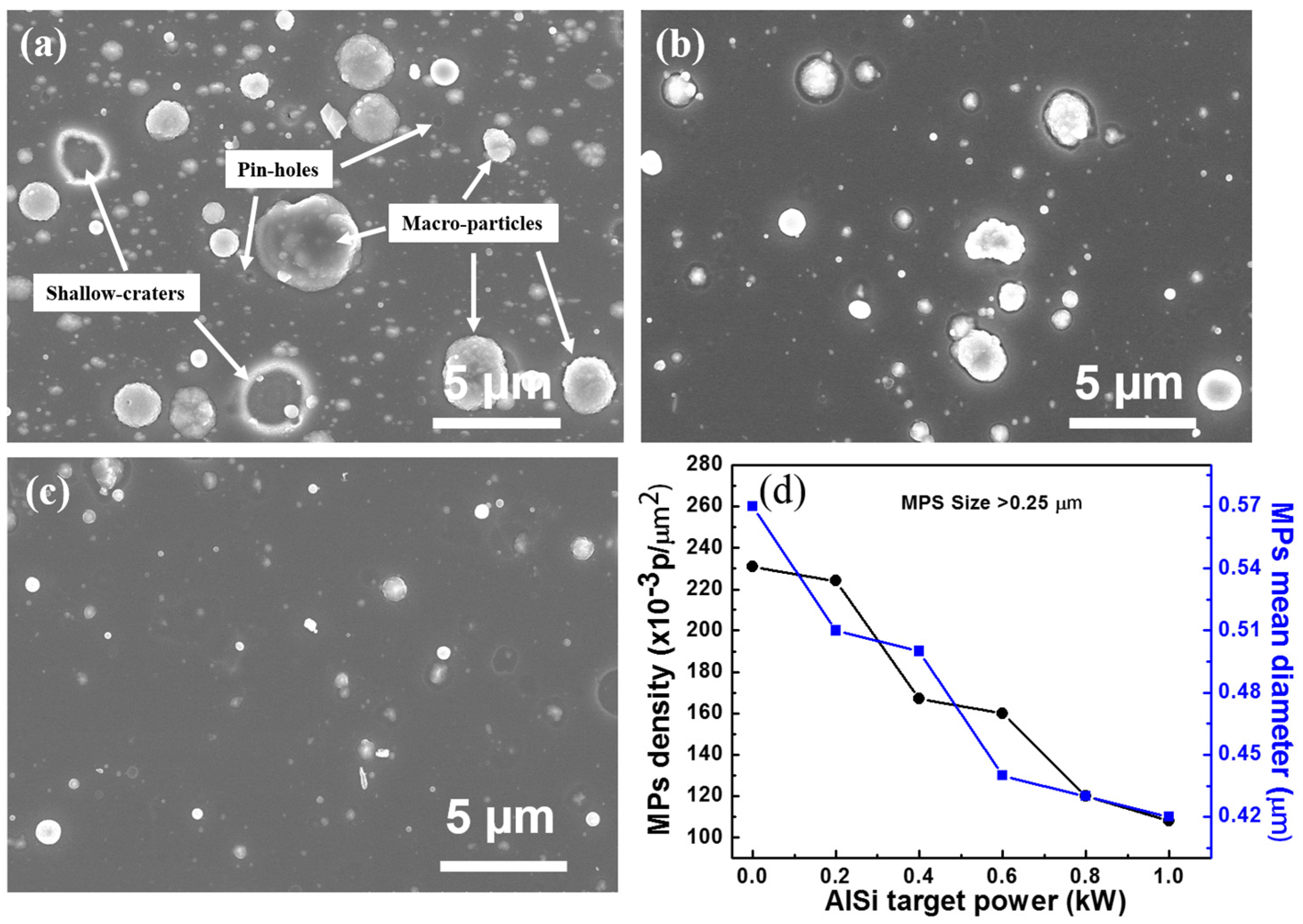
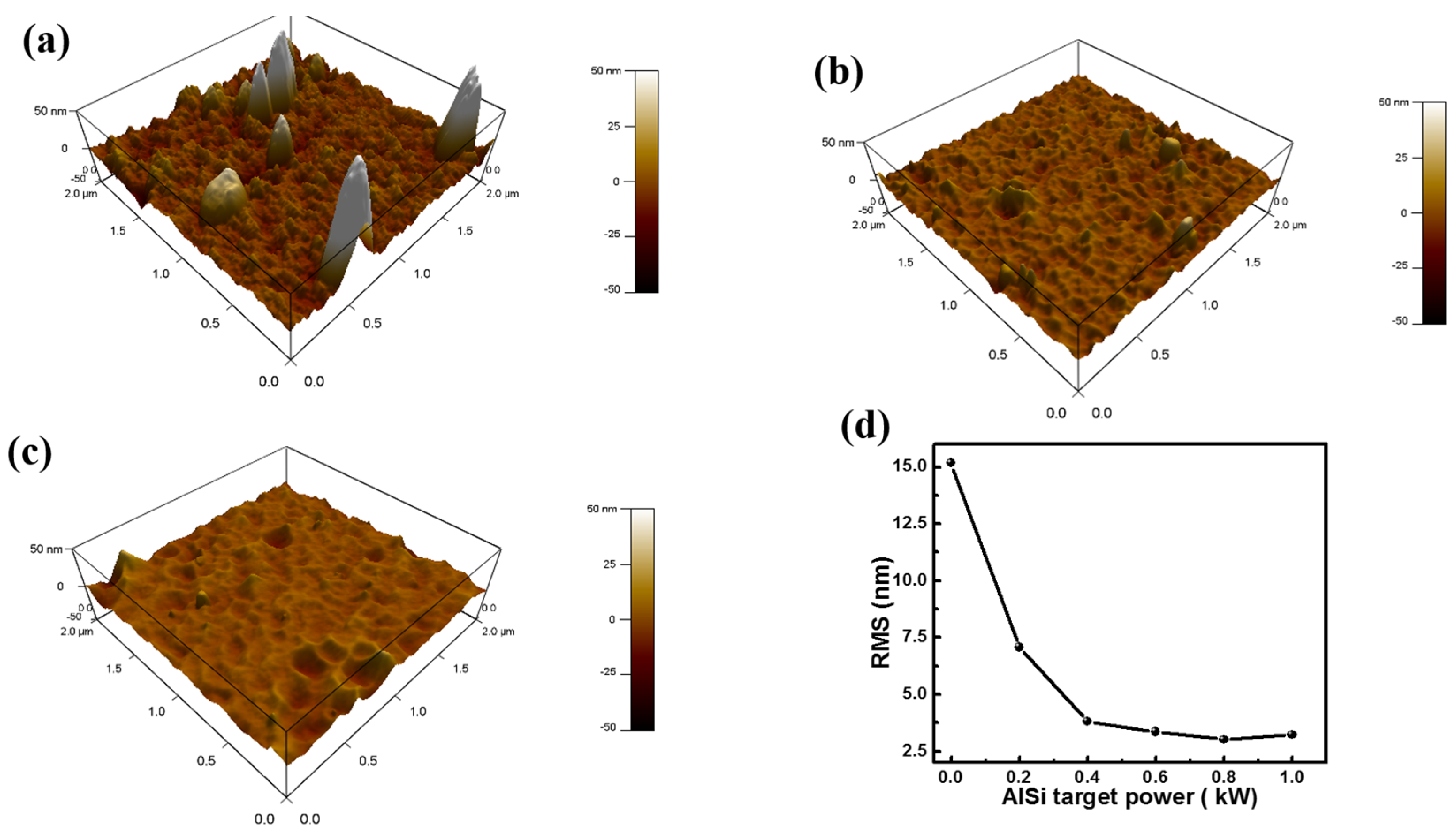
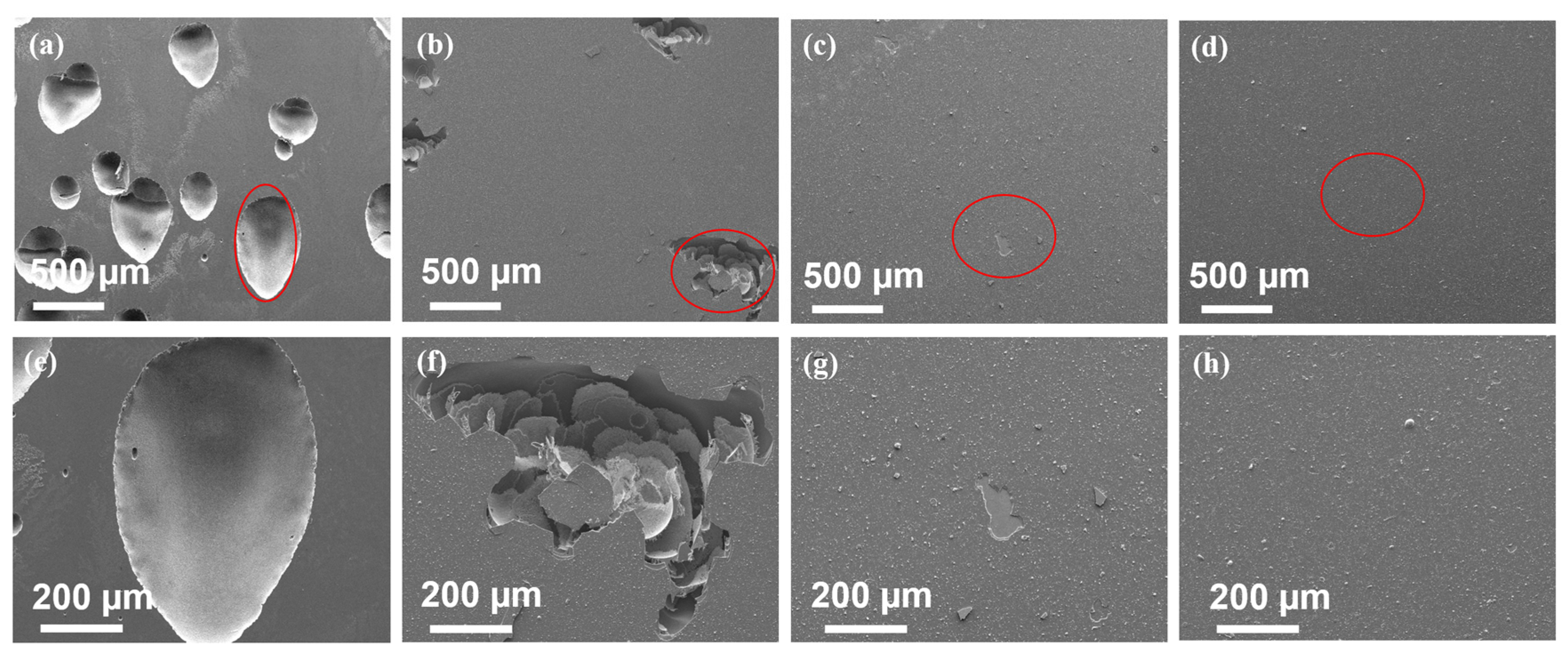
With increasing Al-Si target power, the number of macroparticles greatly decreased through loosely-adhered particles falling off from the surface and the decrease of Cr concentration. The Cr-Al-Si-N film exhibited a maximum hardness of about 27 GPa at a target power of 0.4 kW, which was relatively lower than that of the superhard nanocomposite coatings due to low Si content and not enough formation of an amorphous phase to completely cover the Cr(Al)N crystals.
(2)
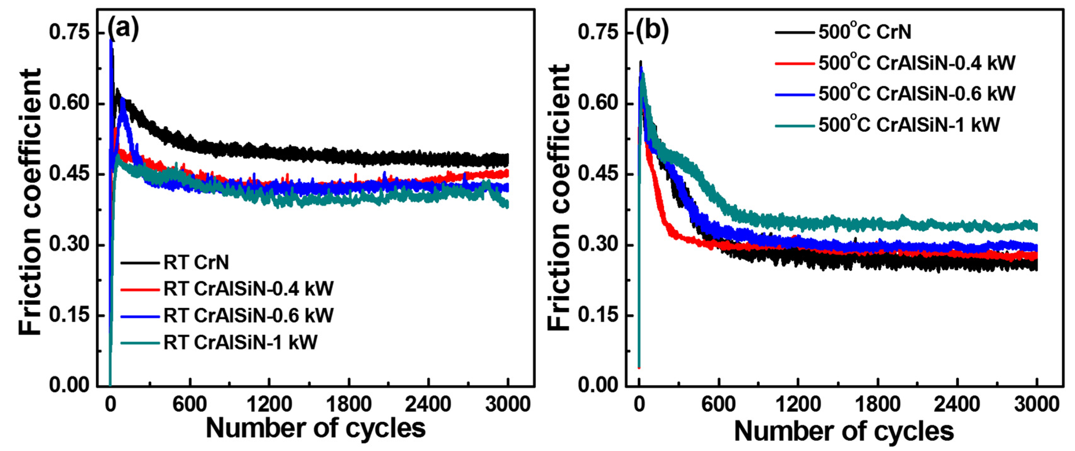
Cr-Al-Si-N coatings showed a lower friction coefficient than the CrN coating at room temperature, which was ascribed to less microparticles (MPs) and an oxide tribolayer generated on Cr-Al-Si-N coatings acting as solid lubrication. When tested at 500 °C, the exhibited wear rate of the Cr-Al-Si-N coatings was smaller than that of the CrN coatings by one order of magnitude. The denser structure, higher hardness and oxide tribolayer led to the enhanced wear resistance of the Cr-Al-Si-N coatings.
(3)
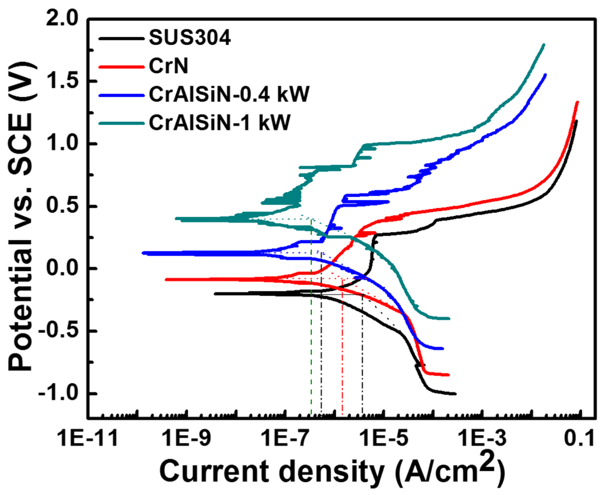
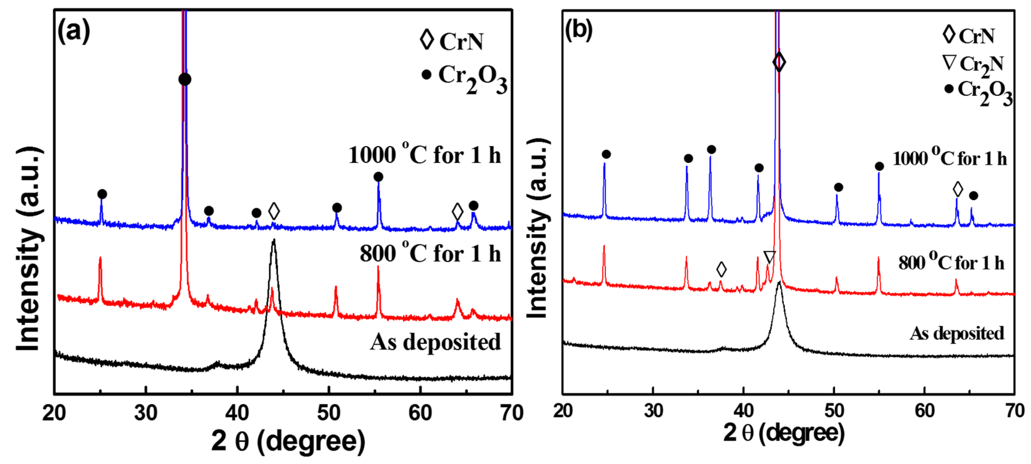
The oxidation experiments were measured at 800 and 1000 °C; these results demonstrated a better oxidation resistance in the Cr-Al-Si-N coatings than the CrN coating. The formation of a dense mixed oxide layer could act as a diffusion barrier to protect underneath the coating. The Cr-Al-Si-N coatings also exhibited excellent corrosion resistance due to their much denser structure compared with the CrN coating.

Acknowledgments

This work was supported by the Global Frontier Program through the Global Frontier Hybrid Interface Materials (GFHIM) of the National Research Foundation of Korea (NRF) funded by the Ministry of Science, ICT & Future Planning (2013M3A6B1078874). In addition, the authors also acknowledge the financial supports of the NSFC project (51522502) and Guangdong Natural Science Fund (2016A050502056).

Author Contributions

Jicheng Ding designed the study, carried out PVD deposition, analyzed the experiment data, and drafted the manuscript. Tengfei Zhang revised and reconstruction of the data in the manuscript. Je Moon Yun did the investigation of samples (XPS, SEM, AFM). Myung Chang Kang did the hardness and oxidation resistance investigation. Qimin Wang and Kwang Ho Kim conceived the study, participated in its design, and supervised the manuscript. All the authors have read and approved the final manuscript.

Conflicts of Interest

The authors declare no conflict of interest.

References

  1. Tricoteaux, A.; Jouan, P.Y.; Guerin, J.D.; Martinez, J.; Djouadi, A. Fretting wear properties of CrN and Cr2N coatings. Surf. Coat. Technol. 2003, 174–175, 440–443. [Google Scholar] [CrossRef]
  2. He, L.Q.; Chen, L.; Xu, Y.X. Interfacial structure, mechanical properties and thermal stability of CrAlSiN/CrAlN multilayer coatings. Mater. Charact. 2017, 125, 1–6. [Google Scholar] [CrossRef]
  3. Yang, B.; Chen, L.; Chang, K.K.; Pan, W.; Peng, Y.B.; Du, Y.; Liu, Y. Thermal and thermomechanical properties of Ti-Al-N and Cr-Al-N coatings. Int. J. Refract. Met. Hard Mater. 2012, 35, 235–240. [Google Scholar] [CrossRef]
  4. Polcar, T.; Cavaleiro, A. High-temperature tribological properties of CrAlN, CrAlSiN and AlCrSiN coatings. Surf. Coat. Technol. 2011, 206, 1244–1251. [Google Scholar] [CrossRef]
  5. Tien, S.K.; Lin, C.H.; Tsai, Y.Z.; Duh, J.G. Effect of nitrogen flow on the properties of quaternary CrAlSiN coatings at elevated temperatures. Surf. Coat. Technol. 2007, 202, 735–739. [Google Scholar] [CrossRef]
  6. Chen, H.W.; Chan, Y.C.; Lee, J.W.; Duh, J.G. Oxidation resistance of nanocomposite CrAlSiN under long-time heat treatment. Surf. Coat. Technol. 2011, 206, 1571–1576. [Google Scholar] [CrossRef]
  7. Caiazzo, F.C.; Sisti, V.; Trasatti, S.P.; Trasatti, S. Electrochemical characterization of multilayer Cr/CrN-based coatings. Coatings 2014, 4, 508–526. [Google Scholar] [CrossRef]
  8. Barshilia, H.C.; Selvakumar, N.; Deepthi, B.; Rajam, K.S. A comparative study of reactive direct current magnetron sputtered CrAlN and CrN coatings. Surf. Coat. Technol. 2006, 201, 2193–2201. [Google Scholar] [CrossRef]
  9. Heo, S.J.; Kim, S.W.; Yeo, I.W.; Park, S.J.; Oh, Y.S. Effect of bias voltage on microstructure and phase evolution of Cr–Mo–N coatings by an arc bonded sputter system. Ceram. Int. 2016, 42, 5231–5237. [Google Scholar]
  10. Kim, G.; Kim, B.; Lee, S.; Hahn, J. Structure and mechanical properties of Cr-Zr-N films synthesized by closed field unbalanced magnetron sputtering with vertical magnetron sources. Surf. Coat. Technol. 2005, 200, 1669–1675. [Google Scholar] [CrossRef]
  11. Shin, J.H.; Wang, Q.M.; Kim, K.H. Microstructural evolution and tribological behavior of Mo-Cu-N coatings as a function of Cu content. Mater. Chem. Phys. 2011, 130, 870–879. [Google Scholar] [CrossRef]
  12. Warcholinski, B.; Gilewicz, A. Effect of substrate bias voltage on the properties of CrCN and CrN coatings deposited by cathodic arc evaporation. Vacuum 2013, 90, 145–150. [Google Scholar] [CrossRef]
  13. Benkahoul, M.; Robin, P.; Martinu, L.; Klemberg-Sapieha, J.E. Tribological properties of duplex Cr-Si-N coatings on SS410 steel. Surf. Coat. Technol. 2009, 203, 934–940. [Google Scholar] [CrossRef]
  14. Wu, W.W.; Chen, W.L.; Yang, S.B.; Lin, Y.; Zhang, S.H.; Cho, T.Y.; Lee, G.H.; Kwon, S.C. Design of AlCrSiN multilayers and nanocomposite coating for HSS cutting tools. Appl. Surf. Sci. 2015, 351, 803–810. [Google Scholar] [CrossRef]
  15. Yadav, P.; Lee, D.B.; Lin, Y.; Zhang, S.H.; Kwon, S.C. High-temperature corrosion of AlCrSiN film in Ar-1% SO2 gas. Coatings 2017, 7, 44. [Google Scholar] [CrossRef]
  16. Tritremmel, C.; Daniel, R.; Polcik, M.L.P.; Mitterer, C. Influence of Al and Si content on structure and mechanical properties of arc evaporated Al-Cr-Si-N thin films. Thin Solid Films 2013, 534, 403–409. [Google Scholar] [CrossRef]
  17. Sabitzer, C.; Paulitsch, J.; Kolozsvári, S.; Rachbauer, R.; Mayrhofer, P.H. Influence of bias potential and layer arrangement on structure and mechanical properties of arc evaporated Al-Cr-N coatings. Vacuum 2014, 106, 49–52. [Google Scholar] [CrossRef]
  18. Reiter, A.E.; Mitterer, C.; Sartory, B. Oxidation of arc-evaporated Al1−xCrxN coatings. J. Vac. Sci. Technol. A 2007, 25, 711–720. [Google Scholar] [CrossRef]
  19. Sabitzer, C.; Paulitsch, J.; Kolozsvári, S.; Rachbauer, R.; Mayrhofer, P.H. Impact of bias potential and layer arrangement on thermal stability of arc evaporated Al-Cr-N coatings. Thin Solid Films 2016, 610, 26–34. [Google Scholar] [CrossRef]
  20. Liu, A.H.; Deng, J.X.; Cui, H.B.; Chen, Y.Y.; Zhao, J. Friction and wear properties of TiN, TiAlN, AlTiN and CrAlN PVD nitride coatings. Int. J. Refract. Met. Hard Mater. 2012, 31, 82–88. [Google Scholar]
  21. Ding, X.Z.; Tan, A.L.K.; Zeng, X.T.; Wang, C.; Yue, T.; Sun, C.Q. Corrosion resistance of CrAlN and TiAlN coatings deposited by lateral rotating cathode arc. Thin Solid Films 2008, 516, 5716–5720. [Google Scholar] [CrossRef]
  22. Huang, L.L.; Zou, C.W.; Xie, W.; Peng, F.; Shao, L.X. Influence of Si contents on the microstructure, mechanical and tribological properties of Cr-Si-N coatings. Ceram. Int. 2016, 42, 5062–5067. [Google Scholar] [CrossRef]
  23. Chang, Y.Y.; Lai, H.M. Oxidation behavior of Si-doped nanocomposite CrAlSiN coatings. Surf. Coat. Technol. 2014, 259, 152–158. [Google Scholar] [CrossRef]
  24. Chen, H.W.; Chan, Y.C.; Lee, J.W.; Duh, J.G. Influence of Si contents on tribological characteristics of CrAlSiN nanocomposite coatings. Surf. Coat. Technol. 2010, 205, 1189–1191. [Google Scholar] [CrossRef]
  25. Chang, C.C.; Chen, H.W.; Lee, J.W.; Duh, J.G. Development of Si-modified CrAlSiN nanocomposite coating for anti-wear application in extreme environment. Surf. Coat. Technol. 2015, 284, 273–280. [Google Scholar] [CrossRef]
  26. Wan, X.S.; Zhao, S.S.; Yang, Y.; Gong, J.; Sun, C. Effects of nitrogen pressure and pulse bias voltage on the properties of Cr-N coatings deposited by arc ion plating. Surf. Coat. Technol. 2010, 204, 1800–1810. [Google Scholar] [CrossRef]
  27. Wang, Q.M.; Kim, K.H. Microstructural control of Cr-Si-N films by a hybrid arc ion plating and magnetron sputtering process. Acta Mater. 2009, 57, 4974–4987. [Google Scholar] [CrossRef]
  28. Li, W.Z.; Evaristo, M.; Cavaleiro, A. Influence of Al on the microstructure and mechanical properties of Cr-Zr-(Al-)N coatings with low and high Zr content. Surf. Coat. Technol. 2012, 206, 3764–3771. [Google Scholar] [CrossRef]
  29. Wang, Q.M.; Kim, K.H. Effect of negative bias voltage on CrN films deposited by arc ion plating. I. Macroparticles filtration and film-growth characteristics. J. Vac. Sci. Technol. 2008, 26, 1258–1266. [Google Scholar] [CrossRef]
  30. Zhang, S.H.; Wang, L.; Wang, Q.M.; Li, M.X. A superhard CrAlSiN superlattice coating deposited by multi-arc ion plating: I. Microstructure and mechanical properties. Surf. Coat. Technol. 2013, 214, 160–167. [Google Scholar] [CrossRef]
  31. Zhang, T.F.; Gan, B.; Park, S.M.; Wang, Q.M.; Kim, K.H. Influence of negative bias voltage and deposition temperature on microstructure and properties of superhard TiB2 coatings deposited by high power impulse magnetron sputtering. Surf. Coat. Technol. 2014, 253, 115–122. [Google Scholar] [CrossRef]
  32. Li, M.S.; Wang, F.H. Effects of nitrogen partial pressure and pulse bias voltage on (Ti,Al)N coatings by arc ion plating. Surf. Coat. Technol. 2003, 167, 197–202. [Google Scholar] [CrossRef]
  33. Zou, C.W.; Wang, H.J.; Li, M.; Yu, Y.F.; Liu, C.S.; Guo, L.P.; Fu, D.J. Microstructure and mechanical properties of Cr-Si-N nanocomposite coatings deposited by combined cathodic arc middle frequency magnetron sputtering. J. Alloys Compd. 2009, 485, 236–240. [Google Scholar] [CrossRef]
  34. Endrino, J.L.; Palacin, S.; Aguirre, M.H.; Gutierrez, A.; Schafers, F. Determination of the local environment of silicon and the microstructure of quaternary CrAl(Si)N films. Acta Mater. 2007, 55, 2129–2135. [Google Scholar] [CrossRef]
  35. Kang, M.C.; Kim, J.S.; Kim, K.H. Cutting performance using high reliable device of Ti-Si-N coated cutting tool for high-speed interrupted machining. Surf. Coat. Technol. 2005, 200, 1939–1944. [Google Scholar] [CrossRef]
  36. Chang, Y.Y.; Chang, C.P.; Wang, D.Y.; Yang, S.M.; Wu, W. High temperature oxidation resistance of CrAlSiN coatings synthesized by a cathodic arc deposition process. J. Alloys Compd. 2008, 461, 336–341. [Google Scholar] [CrossRef]
  37. Kang, M.S.; Wang, T.G.; Shin, J.H.; Nowak, R.; Kim, K.H. Synthesis and properties of Cr-Al-Si-N films deposited by hybrid coating system with high power impulse magnetron sputtering (HiPIMS) and DC pulse sputtering. Trans. Nonferr. Met. Soc. China 2012, 22, 729–734. [Google Scholar] [CrossRef]
  38. Li, W.; Liu, P.; Zhu, X.D.; Pan, D.; Ma, F.C.; Liu, X.K. Effect of Si content on microstructural evolution and superhardness effect of TiN/CrAlSiN nanomultilayered films. J. Alloys Compd. 2015, 650, 592–597. [Google Scholar] [CrossRef]
  39. Pelleg, J.; Zevin, L.Z.; Lungo, S. Reactive-sputter-deposited TiN films on glass substrates. Thin Solid Films 1991, 197, 117–128. [Google Scholar] [CrossRef]
  40. Wang, Q.M.; Kim, K.H. Effect of negative bias voltage on CrN films deposited by arc ion plating. II. Film composition, structure, and properties. J. Vac. Sci. Technol. 2008, 26, 1267–1276. [Google Scholar] [CrossRef]
  41. He, X.M.; Baker, N.; Kehler, B.A.; Walter, K.C.; Nastasi, M. Structure, hardness, and tribological properties of reactive magnetron sputtered chromium nitride films. J. Vac. Sci. Technol. 2000, 18, 30–36. [Google Scholar] [CrossRef]
  42. Park, I.W.; Kang, D.S.; Moore, J.J.; Kwon, S.C.; Rha, J.J.; Kim, K.H. Microstructures, mechanical properties, and tribological behaviors of Cr-Al-N, Cr-Si-N, and Cr-Al-Si-N coatings by a hybrid coating system. Surf. Coat. Technol. 2007, 201, 5223–5227. [Google Scholar] [CrossRef]
  43. Ding, J.C.; Zou, C.W.; Wang, Q.M.; Zeng, K.; Feng, S.C. Effect of bias voltage on the microstructure and hardness of Ti-Si-N films deposited by using high-power impulse magnetron sputtering. J. Korean Phys. Soc. 2016, 68, 351–356. [Google Scholar] [CrossRef]
  44. Jiang, N.; Shen, Y.G.; Zhang, H.J.; Bao, S.N.; Hou, X.Y. Superhard nanocomposite Ti-Al-Si-N films deposited by reactive unbalanced magnetron sputtering. Mater. Sci. Eng. 2006, 135, 1–9. [Google Scholar] [CrossRef]
  45. Zhou, M.; Makino, Y.; Nose, M.; Nogi, K. Phase transition and properties of Ti-Al-N thin films prepared by r.f.-plasma assisted magnetron sputtering. Thin Solid Films 1999, 339, 203–208. [Google Scholar] [CrossRef]
  46. Wang, T.G.; Jeong, D.; Liu, Y.M.; Wang, Q.M.; Iyengar, S.; Melin, S.; Kim, K.H. Study on nanocrystalline Cr2O3 films deposited by arc ion plating: II. Mechanical and tribological properties. Surf. Coat. Technol. 2012, 206, 2638–2644. [Google Scholar] [CrossRef]
  47. Callister, W.D. Fundamentals of Materials Science and Engineering: An Integrated Approach, 2nd ed.; John Wiley & Sons: Hoboken, NJ, USA, 2004; pp. 252–256. [Google Scholar]
  48. Wang, T.G.; Zhao, S.S.; Hua, W.G.; Li, J.B.; Gong, J.; Sun, C. Estimation of residual stress and its effects on the mechanical properties of detonation gun sprayed WC-Co coatings. Mater. Sci. Eng. 2010, 527, 454–461. [Google Scholar] [CrossRef]
  49. Patscheider, J.; Zehnder, T.; Diserens, M. Structure-performance relations in nanocomposite coatings. Surf. Coat. Technol. 2001, 146–147, 201–208. [Google Scholar] [CrossRef]
  50. Lin, J.; Mishra, B.; Moore, J.J.; Sproul, W.D. A study of the oxidation behavior of CrN and CrAlN thin films in air using DSC and TGA analyses. Surf. Coat. Technol. 2008, 202, 3272–3283. [Google Scholar] [CrossRef]
  51. Polcar, T.; Cavaleiro, A. High temperature properties of CrAlN, CrAlSiN and AlCrSiN coatings–Structure and oxidation. Mater. Chem. Phys. 2011, 129, 195–201. [Google Scholar] [CrossRef]
  52. Lin, C.H.; Duh, J.G. Electrochemical impedance spectroscopy (EIS) study on corrosion performance of CrAlSiN coated steels in 3.5 wt % NaCl solution. Surf. Coat. Technol. 2009, 204, 784–787. [Google Scholar] [CrossRef]
  53. Yate, L.; Olcoz, L.M.; Esteve, J.; Lousa, A. Ultra low nanowear in novel chromium/amorphous chromium carbide nanocomposite films. Appl. Surf. Sci. 2017, 420, 707–713. [Google Scholar] [CrossRef]
  54. Pshyk, A.V.; Coy, L.E.; Yate, L.; Zaleski, K.; Nowaczyk, G.; Pogrebnjak, A.D.; Jurga, S. Combined reactive/non-reactive DC magnetron sputtering of high temperature composite AlN-TiB2-TiSi2. Mater. Des. 2016, 94, 230–239. [Google Scholar] [CrossRef]
Figure 1. Schematic diagram of the hybrid deposition system combining arc ion plating (AIP) and high power impulse magnetron sputtering (HiPIMS).
Coatings 07 00119 g001
Figure 2. Al and Si contents in the Cr-Al-Si-N coatings as a function of the Al-Si sputtering power.
Coatings 07 00119 g002
Figure 3. Surface morphologies of the Cr-Al-Si-N coatings with various target powers (a) 0 kW; (b) 0.4 kW; (c) 1 kW, respectively; and (d) variation in densities of microparticles (MPs) and mean diameters of MPs as a function of Al-Si target power.
Coatings 07 00119 g003
Figure 4. Cross-section morphologies of the Cr-Al-Si-N coatings as a function of Al-Si target power (a) 0 kW; (b) 0.4 kW; (c) 1 kW.
Coatings 07 00119 g004
Figure 5. The 3D topographic AFM images (2 µm × 2 µm) of the films with Al-Si target power (a) 0 kW; (b) 0.4 kW; (c) 1 kW, respectively; and (d) the plot of root-mean-square (RMS) roughness with different Al-Si target power.
Coatings 07 00119 g005
Figure 6. The XRD patterns of the Cr-Al-Si-N coatings as a function of Al-Si target power.
Coatings 07 00119 g006
Figure 7. Binding energies of the Cr-Al-Si-N coatings with different Al-Si target power (a) Si2p; (b) Al2p; (c) Cr2p; and (d) N1s.
Coatings 07 00119 g007
Figure 8. Variation in hardness, elastic modulus (a) and compressive stress (b) of the Cr-Al-Si-N coatings as a function of Al-Si target power.
Coatings 07 00119 g008
Figure 9. The friction coefficient curves of the Cr-Al-Si-N coatings deposited with different Al-Si target power in the wear tests at (a) RT, (b) 500 °C.
Coatings 07 00119 g009
Figure 10. The wear rates of the Cr-Al-Si-N coatings deposited with different Al-Si target power under RT and 500 °C.
Coatings 07 00119 g010
Figure 11. XRD patterns of coatings after oxidation tests at 800 °C and 1000 °C (a) CrN; (b) Cr-Al-Si-N in air for 1 h.
Coatings 07 00119 g011
Figure 12. Cross-sectional scanning electron microscopy (SEM) images of CrN (a,c) and Cr-Al-Si-N (b,d) coatings after oxidation tests at 800 °C (a,b), 1000 °C (c,d) in air for 1 h.
Coatings 07 00119 g012
Figure 13. The potentiodynamic polarization curves of the SUS304 steel, CrN, and Cr-Al-Si-N (0.4 kW and 1 kW) coatings in the 3.5 wt % NaCl aqueous solution.
Coatings 07 00119 g013
Figure 14. SEM images of the (a,e) SUS304 steel, (b,f) CrN, (c,g) Cr-Al-Si-N (0.4 kW), and (d,h) Cr-Al-Si-N (1 kW) coatings after corrosion tests in the 3.5 wt % NaCl aqueous solution.
Coatings 07 00119 g014
Table 1. The deposition parameters of the coatings.
Cr Target Current (A)555555555555
Al-Si Target power (kW), 75 Hz, 7.2% duty cycle00.20.40.60.81.0
Deposition time (min)1209090909090
Deposition rate (µm/h)1.451.561.61.621.681.75
Base pressure (Pa)<4.0 × 10⁻³
Working pressure (Pa)8 × 10⁻¹
N2 gas flow (Sccm)100
Ar gas flow (Sccm)50
Substrate temperature (°C)300
Substrate bias voltage (V)−100
Target to substrate distance (mm)250

