Process Parameter Settings and Their Effect on Residual Stresses in WC/W2C Reinforced Iron-Based Arc Sprayed Coatings

Institute of Materials Engineering, TU Dortmund University, Dortmund 44227, Germany
*
Author to whom correspondence should be addressed.
Coatings 2017, 7(8), 125; https://doi.org/10.3390/coatings7080125
Submission received: 28 July 2017
/
Revised: 8 August 2017
/
Accepted: 11 August 2017
/
Published: 15 August 2017
(This article belongs to the Special Issue Mechanical Behavior of Coatings and Engineered Surfaces)
Abstract
:Residual stresses have been a major source of concern, as they are an inevitable consequence of manufacturing and fabrication processes. The magnitude of these stresses is often as high as, or at least, comparable to the yield strength of the material. In terms of arc sprayed coatings, the utilization of bore hole drilling methods presents some practical disadvantages as mechanical parameters (Poisson’s ratio, Young’s modulus) need to be identified in order to determine the residual stress distribution. Curvature techniques using Almen strips are cost- and time-effective methods that can be used for analytical quality assurance. Within the scope of this work, a quantitative study of the amount of residual stresses induced in a twin wire arc spraying (TWAS) process for a given combination of process parameters was conducted using the incremental bore hole drilling method, as well as the curvature method including Almen strips. Therefore, the effect of the primary gas pressure, substrate preheating temperature, and handling parameters, such as the spray angle and gun velocity, which influence the coating deposition as well as the heat input into the substrate, are examined. The experiments were carried out by using an iron-based cored wire with cast tungsten carbides as filling. The results of both methods are in an acceptable accordance with each other. Different stress fields were observed depending on the parameter settings.
1. Introduction
The determination of residual stresses in thermal spray processes is an important technological aim, since the residual stress levels in coatings, and their nature (tensile, or compressive), have a significant effect on the coating characteristics and service life of tools [1]. The presence and distribution of residual stresses affect both the initiation and growth stages of fatigue cracks by changes of the effective mean stress, experienced during fatigue cycling. On the one hand, tensile residual stresses typically increase the susceptibility to cracking and debonding, whereas, on the other hand, compressive residual stresses inhibit crack propagations.
Residual stresses are inherently induced in any coating deposited by means of thermal spraying. In general, the spray parameter settings determine the spray particle conditions (particle temperature, particle velocity), which in turn affect the produced coating properties [2]. In particular, spray particle conditions have a significant influence on the solidification rates, flattening behaviour, and environmental interactions. This leads to different microstructures, residual stresses, and physical properties of the coating [3]. Moreover, studies have shown that the residual stress field in a coating is influenced by the deposition temperature and coating thickness [4,5].
Residual stresses develop in different stages. During deposition, quenching stresses occur due to a rapid cooling and solidification of molten particles (i.e., atomization of the realm of molten pool by means of twin wire arc spraying (TWAS)). Matejicek et al. [6] have revealed that a high level of in-plane tensile stress (of the order of 100 MPa) can develop within each splat during quenching after solidification, as thermal contractions of the splat are constrained by the underlying solid. At the cooling stage, thermal stresses develop due to differences in the thermal expansion of the substrate and the coating. A more detailed study of these two mechanisms can be found in [6,7,8]. Non-conforming strains, rather similar to strains of differential thermal contractions, can occur after deposition as a result of phase changes, structural relaxation, or plastic flow [9].
In terms of mechanical properties, it was shown that by decreasing the residual stresses in the substrates, the adhesion can be improved. When the level of tensile residual stresses increases, the toughness of the coating decreases, as well as the fatigue life of the coated components, whereas compressive residual stresses increase the fatigue life of the coated component [10,11].
Measuring techniques to measure residual stresses in thermally sprayed coatings have been roughly classified by Totemeier and Wright into three categories [1]:
- Measurement of crystallographic lattice parameters;
- Measurement of strains after layer removal or bore hole drilling;
- Measurement of the curvature.
In addition, the applicability of alternative methods, such as ring-core cutting in combination with the digital image correlation technique [12], as well as magnetic techniques based on the Barkhausen noise [13], has been recently demonstrated. An overview of the ring-core methods and other techniques is given elsewhere [14].
Among thermal spraying processes, the TWAS process has great potential for the preparation of mainly amorphous structured coatings, due to rapid cooling and solidification (~105 °C/s) [15] that prevent long-range diffusions and avoids crystallization [16]. The application of Fe-based amorphous coatings, prepared by arc spraying, has been recently investigated [17,18]. The determination of the crystallographic lattice parameters by means of X-ray diffraction (XRD) is applicable for materials which provide a well-defined crystal structure [9,19,20], and therefore, is not suitable for arc sprayed amorphous or partially crystalline coatings. Moreover, the penetration depth is limited to a few microns, depending on the material and the source wavelength [9].
The bore hole drilling method (BHDM), known as a semi-destructive method, is one of the most popular methods to measure residual stresses [9]. A highly sensitive strain rosette is installed on a sample surface. The drilling of a hole on this surface leads to a stress relaxation in the area around the hole. The new stress distribution in this region results in a deformation of the surrounding material, which is measured with installed strain gauges [21]. Several studies show the applicability of BHDM to determine residual stresses in thermally sprayed coatings [22,23,24,25]. Various analytical methods can be used to calculate the residual stresses from measured dynamic expansions. A comprehensive summary of the different analytical methods and their underlying mathematical correlations can be found in the work of Münker [26]. Most analytical methods are based on equations by Kirsch [27]. The two most frequently used analytical methods to determine residual stress profiles are the differential method according to Kockelmann et al. [28,29,30], and the integral method according to Schajer [31,32]. These methods differ in their underlying assumptions. The differential method assumes that only residual stresses of most recently drilled incremental depths contribute to the dynamic expansion on the surface. The relationship between the measured dynamic expansions, and the residual stresses in the component for homogenous material conditions, is described in [33]. In contrast to that, Schajer has shown that not only the residual stresses in the most recently drilled incremental depth contribute to dynamic expansions on the surface [34]. Instead, the influence of residual stresses on the dynamic expansion in all already drilled incremental depths are taken into account by the incremental method.
While the first two methods (measurement of crystallographic lattice parameters by means of XRD and measurement of strains after BHDM) generate precise results when performed correctly, the preparation, recording, and analyses of samples, are in many cases, time consuming and cost-intensive. On the contrary, a measurement of the curvature is simple, less time-consuming, and cost effective, and thus, suitable for many parameter studies. Curvature method measurements are frequently used to determine the stress state in coatings. This method is based on the principle that the deposition of coatings induces stresses, due to the equilibrium force and bending moment in both the coating and the substrate, which cause both to curve. The resulting change in the curvature is measured by different methods [20] and is used to calculate the change in the stress state. Zhu et al. [35] summarized in their work widely adopted equations, such as the Stoney equation, and the analytic model by Clyne et al. [9], to predict the residual stresses based on the induced curvature. Since the deflection (e.g., arc height) of the Almen strip can be used to evaluate the relative residual stresses imparted onto the substrate-coating system during thermal spraying [36], these coupons can be used to determine the stress field.
Due to overlaps of many individual spray particles, arc sprayed coatings are produced, which exhibit properties that mainly depend on the characteristics (size, temperature, and velocity) of the individual impinging particles [15,37,38]. Thus, in-flight particle characteristics are the controlling factors in the splat formation, and in the determination of the morphology of the coating. The atomization behavior (droplet formation), and thus the particle characteristics, are extremely dependent on the electrode phenomena, as well as on the flow behavior of the atomization gas that is used [37,39,40]. Additionally, the disintegration of the extruded metal sheets and the droplet formation are influenced by the selection of the feedstock (material and wire configuration) [38,41,42,43]. Deposits are mainly composed of a heterogeneous microstructure. Phase transformation processes, due to the inherent process characteristics [43,44], among others, provoke the formation of brittle phases, which in turn lead to a degradation of the mechanical properties [45].
Only few studies can be found in literature that address the use of tungsten carbide reinforced iron-based feedstock materials [46,47,48,49,50]. According to these studies, a major objective was on the tribological behavior with respect to their resistance against abrasion and sliding wear. The results indicated some outstanding properties, which emphasize the relevance of tungsten carbide reinforced iron-based feedstock as wear resistant coatings. In terms of tungsten carbide reinforced arc sprayed coatings, the residual stresses were not investigated at all.
Within the scope of this work, a comparative study of the residual stress field in coatings induced by a TWAS process for given process parameter settings was carried out, using two different analytic methods. An iron-based cored wire with a cast tungsten carbide (CTC) filling was used as feedstock. The coating is mainly composed of eutectic carbides, eta carbides (M4C, M6C, and M12C) [50], and interstratified with various Fe-rich oxides. Moreover, the coating is characterized by a lamellar microstructure. Since the microstructure formation of this coating system is heterogeneous, it is yet unknown if the determination of residual stresses from the measured dynamic expansion will provide meaningful data. Therefore, the stress field in coatings is additionally calculated utilizing the curvature method.
2. Materials and Methods
2.1. Substrate and Feedstock Material
Rectangular (20 mm × 50 mm × 10 mm) C45 steel specimens were used as substrates. The surfaces were prepared for the thermal spraying experiments by grit-blasting and cleaning them in an ultrasonic ethanol bath. An iron-based (FeCMnSi) cored wire with 50 wt % of CTC (eutectic mixture of WC and W2C) as a filling was used as feedstock (type AS-850, Durum Verschleissschutz, Willich, Germany).
2.2. Coating Deposition
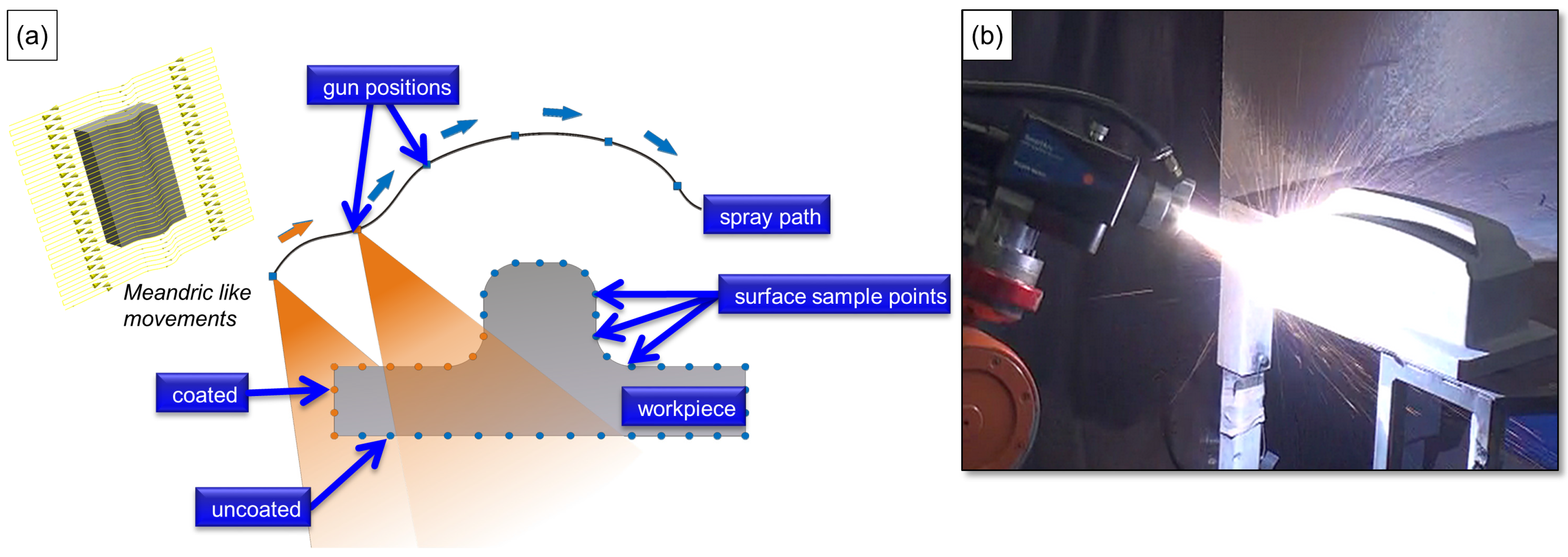
The deposition of thermally sprayed coatings is a promising way to protect stressed surfaces against wear. Since complex components (i.e., deep drawing tool, Figure 1) feature different outer and inner radii, it is possible that spray particles impinge the substrate at off-normal spray angles (<90°), which can result in a discontinuous coating thickness, or locally differing coating properties.
With regard to the deposition of particles, the following factors contribute to off-normal spray angles. On the one hand, due to the electrode phenomena (e.g., arc, magnetohydrodynamics, and eddies), the TWAS process is associated with an increased spray plume divergence across the spray axis behind the intersection point of the electrode tips. The spray plume characteristics were discussed by numerous authors [2,51,52,53,54,55,56,57,58]. On the other hand, limitations of the robot dynamics (depending on the path planning strategy) can lead to deviating spray angles and velocities (e.g., gun velocities) along the robot’s path [52]. Moreover, some path planning strategies allow the shift towards off-normal spray angles, in order to achieve a continuous coating thickness. Against this background, different handling parameters of the spray torch such as the spray-angle at off-normal angles (<90°), as well as a deviating gun velocity, were considered within the experiments. Moreover, the primary gas pressure (PGP) and substrate preheating temperature were taken into account, which have repeatedly been identified as significant factors determining the coating characteristics. The different parameter settings used for the coating deposition within this study are listed in Table 1.
The electrical values for the current and voltage were kept constant (current = 220 A, voltage = 30 V). Two overruns were utilized for the coating deposition. The experiments were conducted using the Smart Arc 350 PPG arc spraying system (Oerlikon Metco, Pfäffikon, Switzerland). According to the setup, a commercially available front end hardware (high profile centering post, No. PPG5I976; air cap body (fine), No. PPG51416) was utilized.
2.3. Coating Characterization and Diagnostic Systems
In order to obtain information about the in-flight spray particle conditions, the temperature and velocity of spray particles were measured in-flight with the Accuraspray-g3 device (Tecnar, Saint-Bruno-de-Montarville, Quebec, Canada) at a stand-off distance ranging from 30 to 110 mm. Cross-section images of the coating, and the interface between the coating and the substrate material, were taken by an AXIOPHOT optical microscope (Carl Zeiss, Oberkochen, Germany). The substrate temperature was determined during spraying by using thermocouples next to the coating/substrate interface.
The residual stress values were obtained by circular high-speed drilling, with a drilling speed of 300,000 rpm. Compared to conventional drilling, the drill used in this study has a diameter of 0.9 mm (type: 805 314 009, Komet Group, Besigheim, Germany) and additionally rotates around an offset axis, so that the overall hole diameter is 1.8 mm. In order to obtain an accurate stress distribution, drilling steps with an identical increment of 20 μm were successively performed through the thickness of the coatings into the substrate. The thus released strains are measured with a strain gauge rosette (type: CEA-06-062UL-120, Vishay Intertechnology, Malvern, Pennsylvania, PA, USA) which consists of three strain gauges (one for 0°, 45°, and 90°, respectively). With the help of an evaluation program, the depth dependent strains are filtered (filter parameter 0.5) and newly exported as splines. The residual stresses are calculated according to the differential method. The drilling depth was confirmed by microscopic analyses using a 3D-Profilometry Infinite Focus (Alicona Imaging, Raaba, Austria).
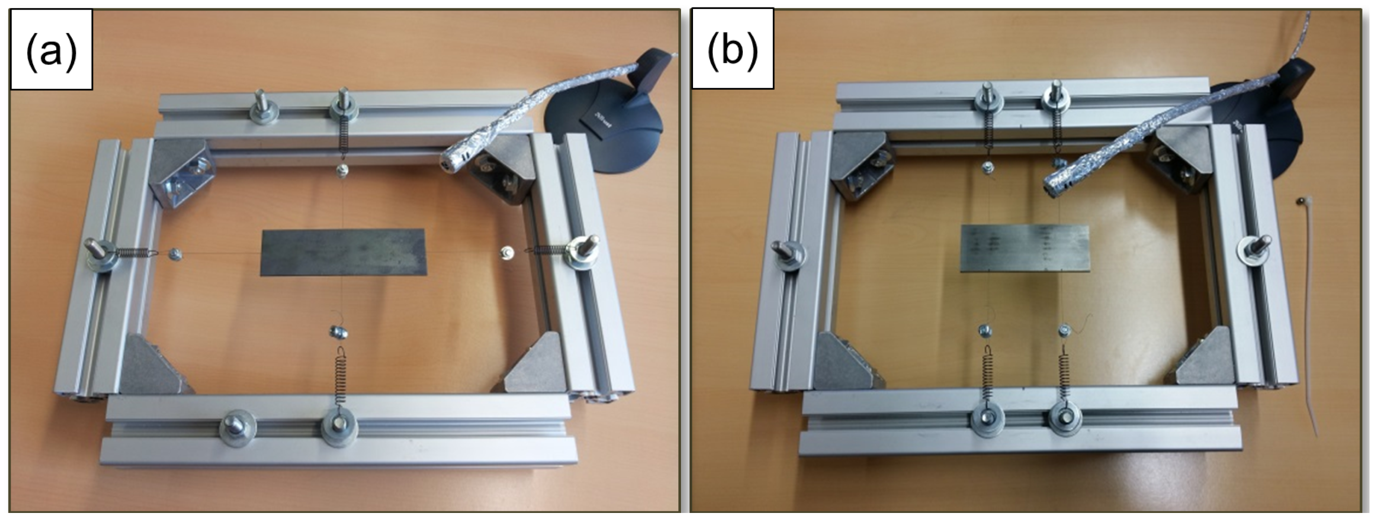
To determine the residual stress state, the Young’s modulus and Poisson’s ratio for both the coating and the substrate are needed. The Poisson’s ratio can be calculated with Equation (1) [59], if the shear and Young’s moduli are known. The shear and Young’s moduli can be obtained using the impulse excitation technique (IET), with separate torsional and flexure vibration modes (Figure 2).
The bar-shaped specimens lie on two wires, which are crossed at right angles for a torsional vibration and parallel for a flexure vibration. The points of support are located just below the vibration nodes of the specimens, where the vibration amplitude is the lowest. After a slight shock, the specimen is exited to vibration at its natural frequency that can be picked up by a microphone and determined using a computer with an analysis software (version 1.15, Audio Funktion-Sweep Generator developed by Grant Connell).
According to DIN EN 834-2, the shear modulus of a bar-shaped free-standing coating with a rectangular cross-section can be calculated with Equation (2) [60]. The free-standing coatings were separated from the substrate using electrical discharge machining.
where G is the shear modulus, ft the resonance frequency of the fundamental torsional vibration, b the width, h the thickness, l the length, and m the mass of the specimen. According to a previous study, it is unnecessary to separate the coating from the substrate to determine the Young’s modulus [61]. The Young’s modulus of coating, Ec, of a specimen with a substrate, can be calculated with Equation (3):
where I is the area moment of inertia of the cross-section with respect to the neutral axis. The indices c and s refer to the coating and the substrate, respectively. The indices mc+s and ff are the mass of the entire specimen, and the resonance frequency of the fundamental flexure vibration, respectively [61]. Each measurement was repeated three times. The average values were taken into account for further investigation. The mechanical coating properties measured by these methods are listed in Table 2.
In addition, the Almen measurement was utilized to evaluate the relative residual stresses transmitted to the substrate-coating system during thermal spraying [36]. Therefore, the stress states of the coatings were evaluated by spraying on a standard Almen strip type N-1S (length l = 76.09 mm, width w = 19.04 mm, thickness hc = 0.785 mm, and a flatness tolerance of ± 0.013 mm, 73.0–74.5 HRa, Standard AMS 2432B). The Almen test was employed to determine the residual stress state by measuring the curvature caused by spraying. The curvature was measured at three different samples. The influence of the sand-blasting process for each sample ID was taken into account. In terms of sand-blasting processes, the surface coverage was analyzed using optical microscopy. A constant peening time of 5 ± 0.2 s, using a coarse grain sized corundum EKF 14, was applied in order to ensure a full area coverage. Thus, the surface of the substrate is roughened and activated prior to the coating process, as the adhesive strength of the coatings get affected by its topography [62,63]. The curvature of the Almen strip was measured before sandblasting, as well as before and after the coating deposition. Measurements were carried out with the convex surface facing up and employing a standard Almen gage (type: TSP-3, Electronics, Mishawaka, IN, USA). During coating, the strip was restrained in a flat position by four screws, as indicated in AMS S13165. The reported normalized value was obtained from the difference between the measured values obtained from the coated and uncoated strips. In accordance with the Almen strip arc height, the Stoney equation (Equation (4)) is used to relate the curvature of the specimen to the stress σc of the film [35]:
The subscripts c and s denote the coating and the substrate, h the thickness, E is the Young’s modulus, which is 200 GPa for SAE 1070, and ν the Poisson’s ratio of about 0.3. κ is the curvature of the substrate.
The curvature ĸ is obtained from the geometric relation, which can be described as (Equation (5)),
whereas d is the maximum displacement at the center of the specimen, and L is the length between the hold-down bolts.
3. Results
The results obtained from the BHDM show a clear interrelationship between the spray angle used for the particle deposition and residual stresses in the coating (Figure 3a,b). Accordingly, the coatings possess low tensile residual stresses close to the surface, which increase (for α = 90°) or remain almost constant (for α = 30°) along the coating thickness towards the substrate. The findings are in good agreement with the results (calculated stress field) derived from the curvature method utilizing the Almen strips (Figure 3c). In this respect, a narrow spray angle of 30° results in low tensile stresses, whereas samples produced with spray angles of 60° and 90° exhibit increased tensile residual stresses.
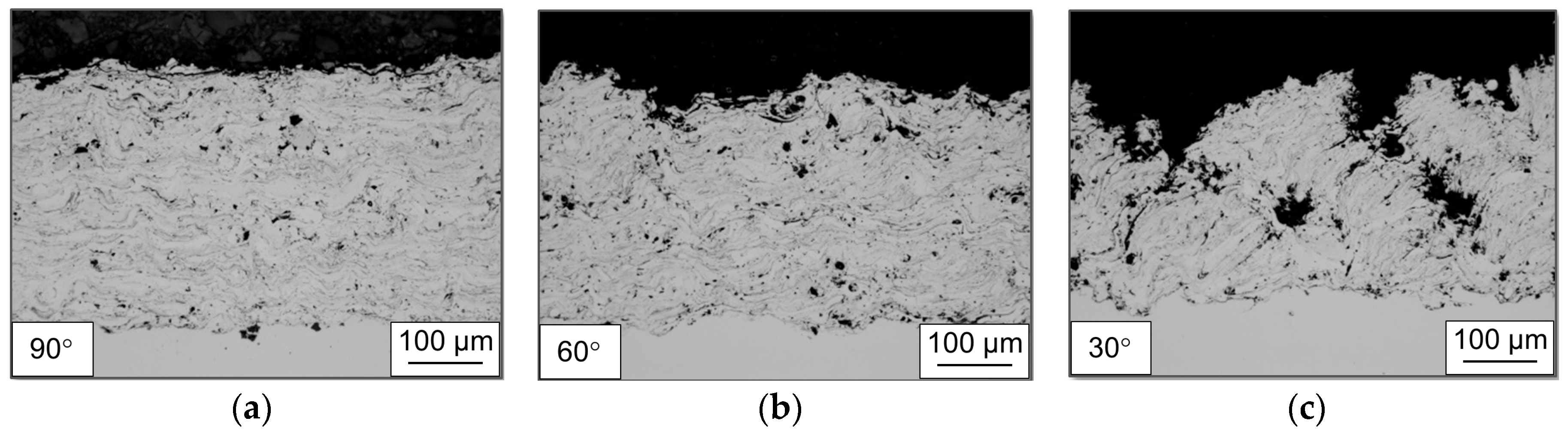
With respect to metallographic investigations of produced sample types, cross-section images reveal that the formation of the microstructure is strongly influenced by the handling parameters of the spray torch, such as the spray angle. For reduced spray angles lower than 90°, the microstructure formation is characterized by a desirable direction of lamellas and splats. Furthermore, structural irregularities (i.e., porous zones) are oriented towards the spray torch. Figure 4 illustrates the different, preferred orientations of the lamellar layers, deposited on specimens with different spray angles. The porous zones, which occur next to the compound layer, are particularly noticeable as they are deposited in a preferred orientation, and occur alternately in a specific frequency as shown for a spray angle of 30°.
With respect to arc spraying, phenomena concerning the splat flattening behavior and splat morphology of droplets has been examined in very few studies [64]. Thus, Abedini et al. [64] studied the effect of the substrate temperature and impact velocity on the splashing behavior of individual droplets. In terms of the handling parameters of the spray torch, only few authors examined the effect of the spray angle on the characteristics of thermally sprayed particles impinging on substrates [65,66,67,68,69]. Regarding plasma-sprayed and cold-sprayed particles, it was revealed that particles deposited at off-normal spray angles (e.g., 60° and 30°) showed significant elongations of flattened splats on the surface.
In this study, different shapes of flattened splats were observed by means of electron microscopy for particles deposited using a spray angle of 60° and 30° (Figure 5). Since the spray angle was reduced to 30°, the spray particles are more likely to possess an elongation of flattened splats. For single splats, it was found that the impinging splats slide over the surface and partially disintegrate.
For the impact of particles at off-normal spray angles, the particle impact velocity can be decomposed in a normal and tangential component, relative to the substrate surface [67,70], which finally affect the splat flattening behavior and the deposition efficiency. A specific analysis on the influence of particles deposited at off-normal spray angles, and their effect on the microstructure as well as on the mechanical properties of arc sprayed coatings, has been conducted by Krebs [70]. For reduced spray angles (providing an increased tangential component), Krebs showed that the impinging particles slide over the surface and mainly adhere to irregularities at the surface. Incidental particles accumulate at these irregularities or protruding peaks. Subsequently, the deposits obtained a sawtooth-like surface. Macro pores were observed at the area between those sawtooth-like structures, which correspond with the findings in this study (Figure 4). This explanation was also used by other authors [71,72].
For thermally sprayed coatings, it is reported that the porosity level and the shape of pores significantly influence the elastic modulus [73,74]. Studies showed that coatings produced with an increase of porosity will exhibit lower in-plane elastic modulus [75] and consequently they are expected to possess lower stresses [76].
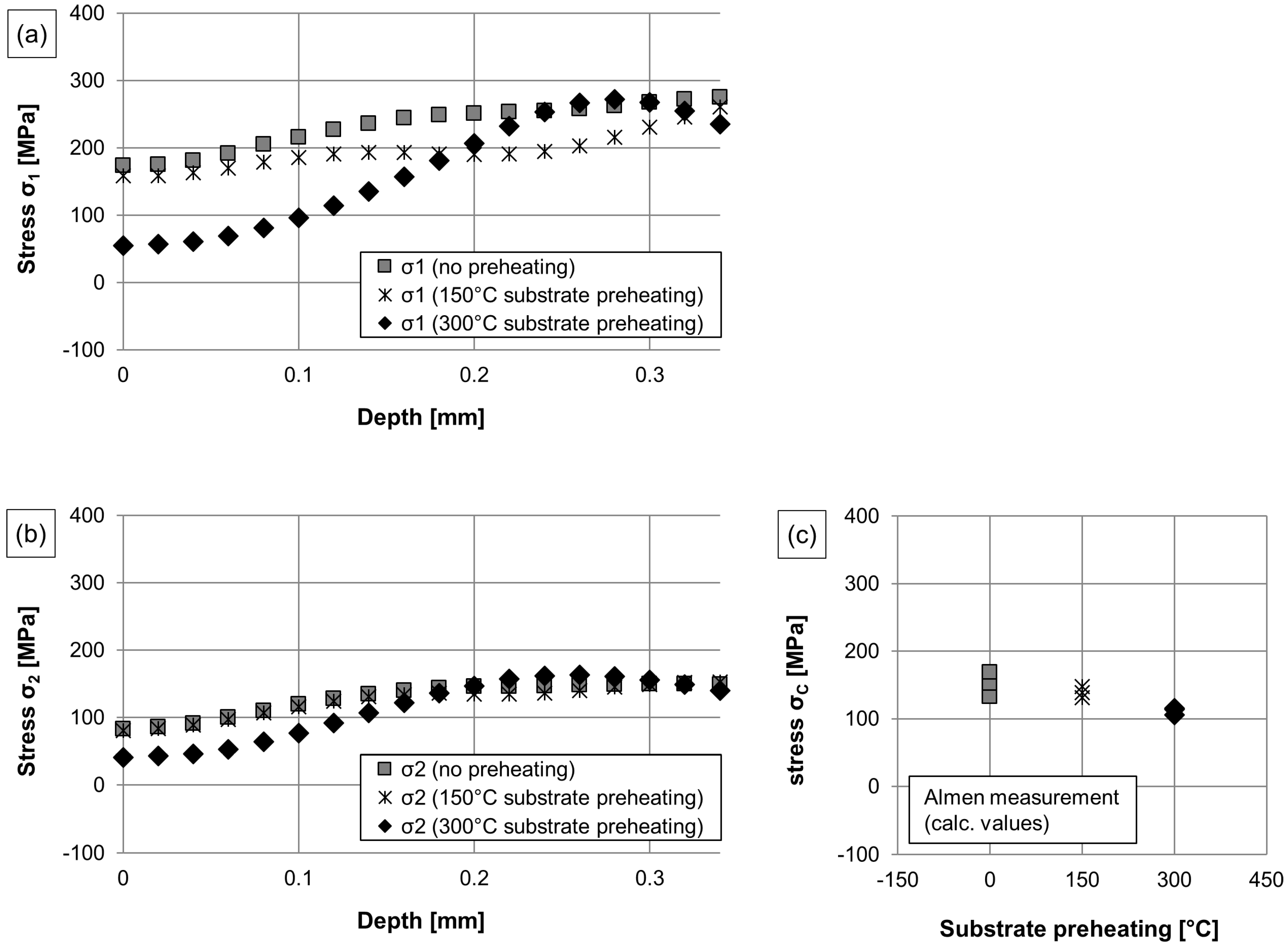
Figure 6 shows the residual stresses determined for different sample types, depending on the substrate preheating temperature.
As obtained from the BHDM, tensile stresses were determined with a gradient towards lower values at the surface (Figure 6a,b). In this respect, the stresses increase along the coating thickness, reaching a maximum next to the coating/substrate interface. This tendency is noticed for all sample types: the preheated (150 °C and 300 °C) and untreated (no preheating) sample types. With respect to the mean average for the in-plane stresses σ1 and σ2, the deposit produced with the use of a substrate preheating temperature of 300 °C exhibits the lowest tensile residual stress state, followed by the deposit produced with a substrate preheating temperature of 150 °C and the sample where no preheating is applied. As observed with the curvature method, the variations of the substrate preheating temperature (no preheating, 150 °C and 300 °C) lead to similar stress states. It is observed that a substrate preheating temperature of 300 °C brings about the lowest stress field in the coating, which was calculated between 106–116 MPa for different specimens (Figure 6c). The calculated stress field in the coating for a substrate preheating temperature of 150 °C is 131–147 MPa towards tensile, compared to 133–168 MPa for specimens deposited without a preheating procedure.
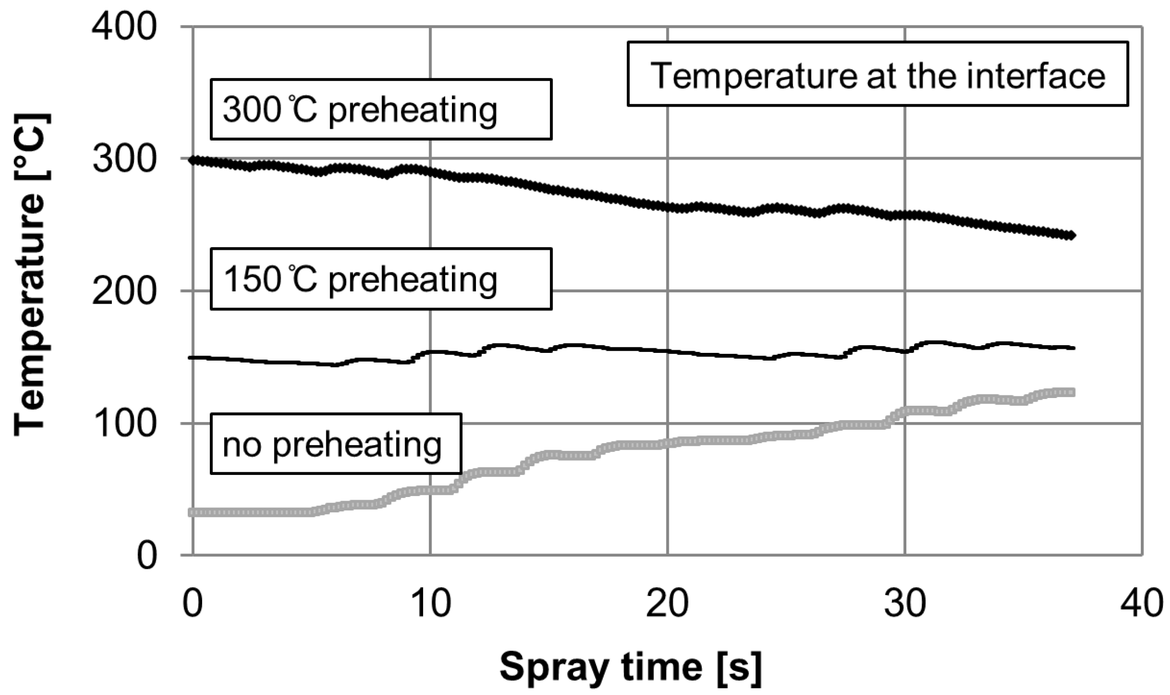
Thermal analyses during spraying were carried out to monitor the heat distribution next to the coating/substrate interface. Figure 7 illustrates the average surface temperature of the substrate during spraying. The three graphs show the evolution of the temperature which was observed during the coating deposition for the different samples.
In terms of no preheating procedure as well as a lower substrate preheating temperature (150 °C), the temperature in the substrate increases during the coating deposition. In particular, in case of a preheating temperature of 150 °C, the heat input during spraying keeps the temperature at the surface of the substrate at an almost constant level. In contrast to that, when applying a preheating temperature of 300 °C, the surface temperature drops to 245 °C at the end of the coating deposition. A preheating of the substrate to a temperature of 150 °C or 300 °C can cause a thermal expansion.
After thermal spraying and during cooling, this expansion will relax, and the substrate shrinks again. W possesses one of the lowest coefficients of thermal expansion (CTE) of about 4.5 × 10⁻⁶ °C−1 amongst pure metals at room temperature [45]. The substitution of Fe by W can lead to a considerable change of the CTE. Assuming that the CTE of the coating follows the rule of mixture, it can be stated that the CTE of the coating is smaller than the CTE of the substrate (according to [77]: α(20–100 °C) = 11.5 × 10⁻⁶ °C−1; α(20–250 °C) = 13.0 × 10⁻⁶ °C−1). Therefore, if both parts can contract freely, the steel substrate will shrink more during cooling than the coating and as they are attached to each other, the shrinkage induces additional compressive stress into the coating, reducing the absolute value of the tensile stress in the arc sprayed coating. Therefore, the value of the tensile stress across the deposit (Figure 6) is reduced, when increasing the preheating temperature of the substrate.
As reported in the literature, the physical properties of both, the substrate and feedstock used for the coating deposition, have a strong influence on the resulting stress state [78,79,80]. Song et al. [79] showed that the magnitude of thermal stress decreases with an increasing preheating temperature of the substrate. Oladijo et al. [80] found that a strong link exists between the stress field in the coating and the physical properties of the substrate, as its CTE relative to that of the substrate, plays a significant role. Thus, a different stress field in the coating was observed for the same feedstock and deposition characteristics when applied on substrates which provide a different CTE.
With regard to the handling parameter, the experiments revealed a significant influence of the gun velocity on the residual stress state across the coating (Figure 8). Thus, the findings obtained from the BHDM showed that a higher gun velocity leads to an increase in tensile residual stresses (Figure 8a,b). Taking the mean average for the in-plane stresses σ1 and σ2 into account, it is found that the deposit produced with the use of an increased gun velocity of 24,000 mm/min possess higher tensile residual stresses, whereas the tensile stress state is more diminished when using a gun velocity of 18,000 mm/min, and 12,000 mm/min, respectively.
With regard to the curvature method using Almen strips, the results indicated the same dependencies as a gun velocity of 24,000 mm/min leads to an increased Almen strip arc height, which in turn corresponds to increased stress values (178–186 MPa) calculated with the Stoney equation (Equation (5)). As opposed to that, utilizing a lower gun velocity of 18,000 mm/min and 12,000 mm/min, the coatings exhibit a reduction in tensile residual stresses (157–184 MPa for 18,000 mm/min, and 133–168 MPa for 12,000 mm/min, respectively), as visible in Figure 8c.
Experiments that monitored the temperature next to the surface of the substrate during spraying for different velocities showed that for a lower gun velocity, a slightly higher surface temperature occurs after each overrun as well as during spraying (Figure 9).
Since there is no flame enthalpy, the heat input is mainly induced by molten spray particles which splash onto the substrate. The spray particle temperature is higher than the steel liquidus temperature. The droplets in the spray plume cool down over the axial spraying distance interval from the realm of the molten pool to 110 mm (spray distance to the substrate). The two colour pyrometry system indicates that the spray particle temperature (for PGP = 0.6 MPa; current = 220 A, voltage = 30 V) is about 2400 ± 10 °C at a stand-off distance of 30 mm, cooling down to 2040 ± 4 °C at an axial distance of 80 mm, and impinges on the substrate with a particle temperature of 1980 ± 4 °C, monitored from the anode side. At the point of impact on the substrate, the droplets solidify rapidly. As opposed to other thermal spraying methods, (e.g., HVOF, APS) the heat input into the substrate is, in total, not significant.
As already described in Figure 8, the residual stresses differ when utilizing different gun velocities. In particular, it is shown that the stress state deviates substantially next to the coating/substrate interface. Accordingly, coating systems produced by using increased gun velocities contain a significant gradient next to the interface. As opposed to that, coating systems produced with a reduced gun velocity possess a slight gradient and lower tensile residual stresses towards the interface (Figure 8a,b). Thermocouple measurements revealed that a lower gun velocity correlates with an increased heat input at the coating/substrate interface, due to the increased particle concentration at the moment of impact. In accordance with that, the coating/substrate interface is exposed to a lower heat input with the use of an increased velocity of the particle-laden spray plume moving over the sample. As a result, fewer molten particles are deposited on the substrate or sublayers. Due to a reduced heat input on the substrate or on the sublayer, it can be stated that the substrate experiences a reduction in thermal stress. As a result, the extra compressive stress of the substrate translated into the coating is diminished. Thus, the mismatch between the residual stress state in the coating and substrate might be increased (Figure 8a,b).
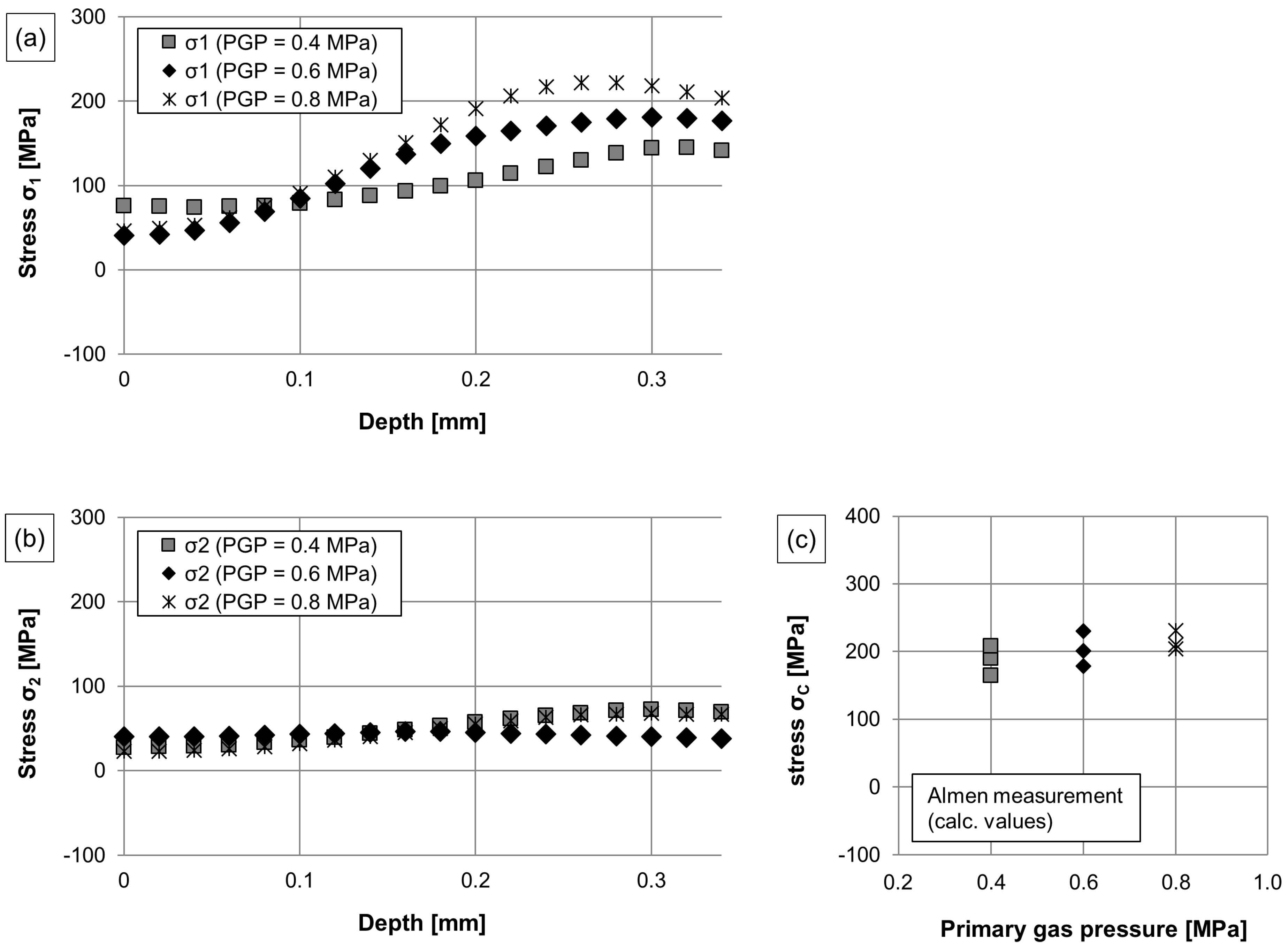
In view of the influence of the PGP applied during spraying, a clear correlation is shown, as an elevated PGP affects the residual stress field generated in the coating (Figure 10). In terms of the BHDM, the measurement reveals that the surface stress is tensile, with a maximum of 40–85 MPa. Across the coating thickness, the stress field in all specimens increases, with a maximum of 150–225 MPa next to the coating/substrate interface. Coatings deposited with the use of a PGP of 0.8 MPa obtain higher tensile residual stresses than coatings deposited with either the use of a PGP of 0.4 MPa and 0.6 MPa (Figure 10a,b). In accordance with that, the results obtained from the curvature method using Almen strips show the same interrelationship. The calculated stress values are 164–207 MPa for PGP = 0.4 MPa, 178–230 MPa for PGP = 0.6 MPa, and 204–231 MPa for PGP = 0.8 MPa, respectively (Figure 10c).
While analysing the thicknesses for samples produced by using a PGP of 0.4, 0.6, and 0.8 MPa, the coating thickness declined with an increased gas pressure of the atomization gas (395 ± 23 µm at 0.4 MPa; 379 ± 18 µm at 0.6 MPa; 361 ± 20 µm at 0.8 MPa). Pyrometric measurements show a slightly higher particle temperature at the point of impact on the substrate using 0.4 MPa (utilizing 220 A, 30 V), which is approximately 2080 ± 18 °C (with vparticle = 86 ± 3 m/s), whereas at a PGP of 0.8 MPa (utilizing 220 A, 30 V) the particle temperature is approximately 1965 ± 25 °C (with vparticle = 140 ± 7 m/s). At higher relative velocities between the continuous phase (gas phase) and dispersed phase (particle phase), the convective heat transfer of spray particles increases as the heat transfer coefficient increases with an increase of the gas velocity [81,82,83]. The heat transfer coefficient significantly depends on the type of flow as well. In the case of a laminar flow, the heat transfer coefficient is low, whereas in a turbulent flow the coefficient is higher [81,82]. Depending on the spray nozzle design, the flow characteristics across the spray plume may differ at different PGPs used within this study.
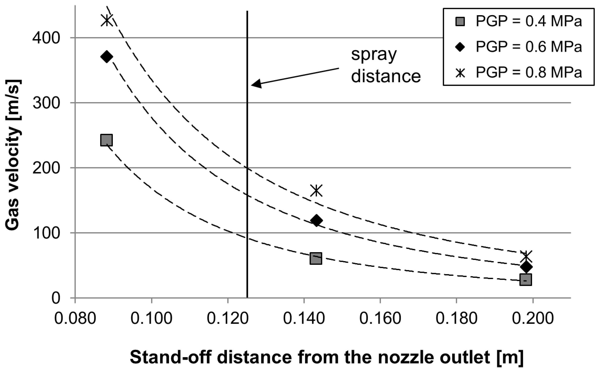
Nevertheless, the particle temperature with the use of a PGP of 0.4 MPa does not vary significantly, when compared to a PGP of 0.8 MPa. Thus, the heat input at the moment of impact (molten particles splash on the surface) should not be different. It is more likely that the expanded air jet (the use of compressed air at room temperature) works as a front cooling. From differential pressure flow measurements, the gas velocity resulting from different PGPs of the atomization gas is monitored at varied stand-off distances (Figure 11).
The values indicate a high gas velocity after the intersection point of the electrode tips, which is about 250 m/s for 0.4 MPa (at a stand-off distance of 0.088 m), and more than 420 m/s for 0.8 MPa (at a stand-off distance of 0.088 m). The measurement is limited up to a gas velocity of 428 m/s, due to the calibration of the transmitter used in the experiments. The gas velocity reduces significantly with growing stand-off distances, which is about 60 m/s for 0.4 MPa, 119 m/s for 0.6 MPa, 165 m/s for 0.8 MPa, captured at a stand-off distance of 0.143 m. Based on these findings, it can be stated that the use of 0.8 MPa for the atomization gas pressure provides a higher gas velocity at a spray distance of 110 mm. Utilizing a calorimetric measurement system, the volume flow rate was determined, which is about 1865 L/min for 0.4 MPa, 2485 L/min for 0.6 MPa, and 3080 L/min for 0.8 MPa, respectively.
Accordingly, a reduced gas flow rate and gas velocity of the atomization gas (PGP = 0.4 MPa) provides a marginal cooling effect, whereas an increased gas flow rate and gas velocity (PGP = 0.8 MPa) dissipates the heat, which is distributed at the surface of the specimen, more effectively. Further investigations need to be conducted in order to examine the cooling effects during TWAS. One approach would be to investigate the effect of a preheated atomization gas supply and consequently its potential impact on the heat dissipation across the coating/substrate interface.
4. Conclusions
Several reasons can cause the trapping of residual stresses inside the coating composite, such as the mismatch between thermal expansion coefficient of the hard particle (WC/W2C) and the metallic matrix, different thermal expansion coefficient in longitudinal and transverse directions of a layer, different expansion and contraction of consecutive layers (WC/W2C, metallic binder) as a result of their different arrangements, and a non-uniform solidification. The BHDM represents a promising technique to measure the residual stress distribution described by the ASTM standard. It is still a challenge to measure the relieved strains accurately. In terms of thermal spray coatings, in particular for heterogeneous coatings such as TWAS, the utilization of the strain gauge rosette presents some practical disadvantages, as mechanical parameters (the Poisson’s ratio and Young’s modulus) need to be identified.
Curvature techniques, including the deflection of Almen strips, present an alternative approach to measure the residual stress state to save time and costs. Especially for TWAS, which is an inexpensive coating deposition method in thermal spraying, Almen strips can be used for an analytical quality assurance. Furthermore, due to the fact that arc spayed coatings are prone to be partially nanocrystalline and amorphous, the determination of residual stresses using XRD analyses is limited.
In this study, the incremental BHDM was used to determine the residual stresses distribution across the coating into the substrate. The released strains for each step in the bore hole depth were measured by a strain gauge rosette. Using the differential method, residual stresses were calculated. For the calculation of the residual stresses, the Poisson’s ratio, shear modulus, and Young’s modulus were examined. The findings were compared to the results obtained from the curvature method utilizing Almen strips. In comparison, the results are in an acceptable accordance to each other, as the measurement of deflection using Almen strips in combination with the Stoney equation and the BHDM, lead to similar residual stress states for different spray parameter settings. None of the results describe compressive residual stresses. With regard to the substrate and feedstock used within this study, it is found that all different sample types exhibit tensile residual stresses. On the one hand, utilizing a reduced spray angle, the coating possesses lower tensile residual stresses. On the other hand, the use of a spray angle of 90 °C lead to an increased stress field. Furthermore, the experiments showed that the gun velocity (and the heat input as the amount of molten particle contribute to the heat influx), and the preheating procedure, as the amount of quenching stresses is influenced by physical properties (e.g., CTE) of splats relative to the substrate material, lead to a different stress state. In particular, coating systems produced by increased gun velocities contain a significant gradient next to the coating/substrate interface, which can lead to a mismatch, moreover, acting as the driving force to debond at the interface. Moreover, the experiments showed that coatings deposited with the use of 0.8 MPa obtain higher residual tensile stresses than coatings deposited with the use of 0.4 MPa, and 0.6 MPa, respectively. Regarding these findings, it can be stated that an increased gas velocity caused by a higher PGP works as a front cooling. Thus, the gas flow characteristics (PGP = 0.4 MPa) in the expanded spray jet provides a marginal cooling effect, whereas the flow characteristics at an elevated PGP (PGP = 0.8 MPa) dissipates the heat, which is distributed at the surface of the specimen, better. Accordingly, a different stress field in the coatings was observed.
Acknowledgments
The authors gratefully acknowledge the financial support of the DFG (German Research Foundation) within the Collaborative Research Centre SFB 708, projects A1 and C2.
Author Contributions
Leif Hagen conceived and designed the experiments; Leif Hagen and Weifeng Luo performed the experiments, analyzed the data, and wrote the paper. Wolfgang Tillmann supervised the work.
Conflicts of Interest
The authors declare no conflict of interest.
References
- Totemeier, T.C.; Wright, J.K. Residual stress determination in thermally sprayed coatings—A comparison of curvature models and X-ray techniques. Surf. Coat. Technol. 2006, 200, 3955–3962. [Google Scholar] [CrossRef]
- Gedzevicius, I.; Valiulis, A.V. Analysis of wire arc spraying process variables on coatings properties. J. Mater. Process. Technol. 2006, 175, 206–211. [Google Scholar] [CrossRef]
- Sampath, S.; Jiang, X.; Matejicek, J.; Prchlik, L.; Kulkarni, A.; Vaidya, A. Role of thermal spray processing method on the microstructure, residual stress and properties of coatings: An integrated study for Ni–5 wt % Al bond coats. Mater. Sci. Eng. A 2004, 364, 216–231. [Google Scholar] [CrossRef]
- Evans, A.G.; Crumley, G.B.; Demaray, R.E. On the mechanical behavior of brittle coatings and layers. Oxid. Met. 1983, 20, 193–216. [Google Scholar] [CrossRef]
- Scardi, P.; Leoni, M.; Bertamini, L. Residual stresses in plasma sprayed partially stabilised zirconia TBCs: Influence of the deposition temperature. Thin Solid Films 1996, 278, 96–103. [Google Scholar] [CrossRef]
- Matejicek, J.; Sampath, S. Intrinsic residual stresses in single splats produced by thermal spray processes. Acta Mater. 2001, 49, 1993–1999. [Google Scholar] [CrossRef]
- Pina, J.; Dias, A.; Lebrun, J. Study by X-ray diffraction and mechanical analysis of the residual stress generation during thermal spraying. Mater. Sci. Eng. A 2003, 347, 21–31. [Google Scholar] [CrossRef]
- Kuroda, S.; Dendo, T.; Kitahara, S. Quenching stress in plasma sprayed coatings and its correlation with the deposit microstructure. J. Therm. Spray Technol. 1995, 4, 75–84. [Google Scholar] [CrossRef]
- Clyne, T.W.; Gill, S.C. Residual stresses in thermal spray coatings and their effect on interfacial adhesion: A review of recent work. J. Therm. Spray Technol. 1996, 5, 401–418. [Google Scholar] [CrossRef]
- Chien, H.; Diaz-Jimenez, C.; Rohrer, G.S.; Ban, Z.; Prichard, P.; Liu, Y. The influence of residual thermal stresses on the mechanical properties of multilayer α-Al2O3/TiCxN1−x coatings on WC/Co cutting tools. Surf. Coat. Technol. 2013, 215, 119–126. [Google Scholar] [CrossRef]
- Richard, C.S.; Béranger, G.; Lu, J.; Flavenot, J.F. The influences of heat treatments and interdiffusion on the adhesion of plasma-sprayed NiCrAlY coatings. Surf. Coat. Technol. 1996, 82, 99–109. [Google Scholar] [CrossRef]
- Zhu, J.G.; Xie, H.M.; Li, Y.J.; Hu, Z.X.; Luo, Q.; Gu, C.Z. Interfacial residual stress analysis of thermal spray coatings by miniature ring-core cutting combined with DIC method. Exp. Mech. 2014, 54, 127–136. [Google Scholar] [CrossRef]
- Vourna, P.; Ktena, A.; Tsakiridis, P.E.; Hristoforou, E. A novel approach of accurately evaluating residual stress and microstructure of welded electrical steels. NDT E Int. 2015, 71, 33–42. [Google Scholar] [CrossRef]
- Lunt, A.J.; Baimpas, N.; Salvati, E.; Dolbnya, I.P.; Sui, T.; Ying, S.; Korsunsky, A.M. A state-of-the-art review of micron-scale spatially resolved residual stress analysis by FIB-DIC ring-core milling and other techniques. J. Strain Anal. Eng. Des. 2015, 50, 426–444. [Google Scholar] [CrossRef]
- Newbery, A.P.; Grant, P.S.; Neiser, R.A. The velocity and temperature of steel droplets during electric arc spraying. Surf. Coat. Technol. 2005, 195, 91–101. [Google Scholar] [CrossRef]
- Zhou, J.; Walleser, J.K.; Meacham, B.E.; Branagan, D.J. Novel in situ transformable coating for elevated-temperature applications. J. Therm. Spray Technol. 2010, 19, 950–957. [Google Scholar] [CrossRef]
- Guo, W.; Wu, Y.; Zhang, J.; Yuan, W. Effect of the long-term heat treatment on the cyclic oxidation behavior of Fe-based amorphous/nanocrystalline coatings prepared by high-velocity arc spray process. Surf. Coat. Technol. 2016, 307, 392–398. [Google Scholar] [CrossRef]
- Cheng, J.; Zhao, S.; Liu, D.; Feng, Y.; Liang, X. Microstructure and fracture toughness of the FePSiB-based amorphous/nanocrystalline coatings. Mater. Sci. Eng. A 2017, 696, 341–347. [Google Scholar] [CrossRef]
- Matejícek, J.; Sampath, S.; Dubsky, J. X-ray residual stress measurement in metallic and ceramic plasma sprayed coatings. J. Therm. Spray Technol. 1998, 7, 489–496. [Google Scholar] [CrossRef]
- Withers, P.J.; Bhadeshia, H.K.D.H. Residual stress. Part 1–Measurement techniques. Mater. Sci. Technol. 2001, 17, 355–365. [Google Scholar] [CrossRef]
- Huang, X.; Liu, Z.; Xie, H. Recent progress in residual stress measurement techniques. Acta Mech. Solida Sin. 2013, 26, 570–583. [Google Scholar] [CrossRef]
- Santana, Y.Y.; La Barbera-Sosa, J.G.; Staia, M.H.; Lesage, J.; Puchi-Cabrera, E.S.; Chicot, D.; Bemporad, E. Measurement of residual stress in thermal spray coatings by the incremental hole drilling method. Surf. Coat. Technol. 2006, 201, 2092–2098. [Google Scholar] [CrossRef]
- Lille, H.; Koo, J.; Rybchikov, A.; Toropov, S.; Veinthal, R.; Surzhenkov, A. Comparative analysis of residual stresses in flame-sprayed and electrodeposited coatings using substrate deformation and hole-drilling methods. In Proceedings of the 7th International Conference of DAAAM Baltic, Industrial Engineering, Tallinn, Estonia, 22–24 April 2010. [Google Scholar]
- Valente, T.; Bartuli, C.; Sebastiani, M.; Loreto, A. Implementation and development of the incremental hole drilling method for the measurement of residual stress in thermal spray coatings. J. Therm. Spray Technol. 2005, 14, 462–470. [Google Scholar] [CrossRef]
- Santana, Y.Y.; Renault, P.O.; Sebastiani, M.; La Barbera, J.G.; Lesage, J.; Bemporad, E.; Le Bourhis, E.; Puchi-Cabrera, E.S.; Staia, M.H. Characterization and residual stresses of WC–Co thermally sprayed coatings. Surf. Coat. Technol. 2008, 202, 4560–4565. [Google Scholar] [CrossRef]
- Münker, J. Untersuchung und Weiterentwicklung der Auswertemethoden für teilzerstörende Eigenspannungsmessverfahren. Ph.D. Thesis, Universität-Gesamthochschule Siegen, Siegen, Germany, 1993. (In German). [Google Scholar]
- Kirsch, G. Die Theorie der Elastizität und die Bedürfnisse der Festigkeitslehre; Springer: Berlin, Germany, 1898; pp. 797–807. (In German) [Google Scholar]
- Schwarz, T.; Kockelmann, H. Die bohrlochmethode—ein für viele anwendungsbereiche optimales verfahren zur experimentellen ermittlung von eigenspannungen. Messtechnische Briefe 1993, 29, 33–38. (In German) [Google Scholar]
- Kockelmann, H.; König, G. Abschlussbericht zum DFG-Forschungsvorhaben Ko 896/2-1 Kennwort: Bohrlochemethode; Materialprüfungsanstalt Universität Stuttgart (MPA Stuttgart): Stuttgart, Germany, 1987. (In German) [Google Scholar]
- König, G. Ein Beitrag zur Weiterentwicklung teilzerstörender Eigenspannungsmeßverfahren. Ph.D. Thesis, Materialprüfungsanstalt Universität Stuttgart (MPA Stuttgart), Stuttgart, Germany, 1991. (In German). [Google Scholar]
- Schajer, G.S. Measurement of non-uniform residual stresses using the hole-drilling method. Part II—Practical application of the integral method. J. Eng. Mater. Technol. 1988, 110, 344–349. [Google Scholar] [CrossRef]
- Schajer, G.S. Measurement of Non-uniform residual stresses using the hole-drilling method. Part I—Stress calculation procedures. J. Eng. Mater. Technol. 1988, 110, 338–343. [Google Scholar] [CrossRef]
- Schwarz, T. Beitrag zur Eigenspannungsermittlung an isotropen, anisotropen sowie inhomogenen, schichtweise aufgebauten Werkstoffen mittels Bohrlochmethode und Ringkernverfahren. Ph.D. Thesis, Materialprüfungsanstalt Universität Stuttgart (MPA Stuttgart), Stuttgart, Germany, 1996. (In German). [Google Scholar]
- Schajer, G.S. Application of finite element calculations to residual stress measurements. J. Eng. Mater. Technol. 1981, 103, 157–163. [Google Scholar] [CrossRef]
- Zhu, J.; Xie, H.; Hu, Z.; Chen, P.; Zhang, Q. Residual stress in thermal spray coatings measured by curvature based on 3D digital image correlation technique. Surf. Coat. Technol. 2011, 206, 1396–1402. [Google Scholar] [CrossRef]
- Sauer, J.P.; Sahoo, P. HVOF process control using Almen and temperature measurement. In Thermal Spray 2001: New Surfaces for a New Millennium, Proceedings of the International Thermal Spray Conference, Singapore, 28–30 May 2001; ASM International: Materials Park, OH, USA, 2001. [Google Scholar]
- Hussary, N.A.; Heberlein, J.V.R. Effect of system parameters on metal break-up and particle formation in the wire arc spray process. J. Therm. Spray Technol. 2007, 16, 140–152. [Google Scholar] [CrossRef]
- Pourmousa, A.; Mostaghimi, J.; Abdini, A.; Chandra, S. Particle size distribution in a wire-arc spraying system. J. Therm. Spray Technol. 2005, 14, 502–510. [Google Scholar] [CrossRef]
- König, J.; Lahres, M.; Zimmermann, S.; Schein, J. Established and adapted diagnostic tools for investigation of a special twin-wire arc spraying process. J. Therm. Spray Technol. 2016, 25, 1233–1254. [Google Scholar] [CrossRef]
- Devillers, J.B.; Liao, H.; Coddet, C.; Malhaire, J.M. Influence of gas flow parameters and nozzle design on secondary atomization in a rotating twin-wire arc spray system. In Thermal Spray 2015, Proceedings of the International Thermal Spray Conference, Long Beach, CA, USA, 11–14 May 2015; ASM International: Materials Park, OH, USA, 2015. [Google Scholar]
- Tillmann, W.; Vogli, E.; Abdulgader, M.; Gurris, M.; Kuzmin, D.; Turek, S. Particle behavior during the arc spraying process with cored wires. J. Therm. Spray Technol. 2008, 17, 966–973. [Google Scholar] [CrossRef]
- Newbery, A.P.; Rayment, T.; Grant, P.S. A particle image velocimetry investigation of in-flight and deposition behaviour of steel droplets during electric arc spray forming. Mater. Sci. Eng. 2004, 383, 137–145. [Google Scholar] [CrossRef]
- Tillmann, W.; Abdulgader, M. Wire composition: Its effect on metal disintegration and particle formation in twin-wire arc-spraying process. J. Therm. Spray Technol. 2013, 22, 352–362. [Google Scholar] [CrossRef]
- Newbery, A.P.; Grant, P.S. Oxidation during electric arc spray forming of steel. J. Mater. Process. Technol. 2006, 178, 259–269. [Google Scholar] [CrossRef]
- Sheppard, P.; Koiprasert, H. Effect of W dissolution in NiCrBSi–WC and NiBSi–WC arc sprayed coatings on wear behaviors. Wear 2014, 317, 194–200. [Google Scholar] [CrossRef]
- He, D.J.; Fu, B.J.; Jiang, J.M.; Li, X.J. Microstructure and wear performance of arc sprayed Fe-FeB-WC Coatings. J. Therm. Spray Technol. 2008, 17, 757–761. [Google Scholar] [CrossRef]
- Tillmann, W.; Klusemann, B.; Nebel, J.; Svendsen, B. Analysis of the mechanical properties of an arc-sprayed WC-FeCSiMn coating: Nanoindentation and simulation. J. Therm. Spray Technol. 2011, 20, 328–335. [Google Scholar] [CrossRef]
- Xu, B.; Zhu, Z.; Ma, S.; Zhang, W.; Liu, W. Sliding wear behavior of Fe–Al and Fe–Al/WC coatings prepared by high velocity arc spraying. Wear 2004, 257, 1089–1095. [Google Scholar] [CrossRef]
- Tillmann, W.; Luo, W.; Selvadurai, U. Wear analysis of thermal spray coatings on 3D surfaces. J. Therm. Spray Technol. 2014, 23, 245–251. [Google Scholar] [CrossRef]
- Tillmann, W.; Hagen, L.; Schröder, P. Tribological characteristics of tungsten carbide reinforced arc sprayed coatings using different carbide grain size fractions. Tribol. Ind. 2017, 39, 168–182. [Google Scholar] [CrossRef]
- Paczkowski, G.; Rupprecht, C.; Wielage, B. High-velocity arc spraying—The renaissance of a coating process. Therm. Spray Bull. 2012, 2, 140–147. [Google Scholar]
- Wiederkehr, T.; Müller, H.; Hegels, D.; Tillmann, W.; Hagen, L. Fast coating deposition simulation for path planning and iterative net-shape optimization on complex workpieces. In Thermal Spray 2015, Proceedings of the International Thermal Spray Conference, Long Beach, CA, USA, 11–14 May 2015; ASM International: Materials Park, OH, USA, 2015. [Google Scholar]
- Tillmann, W.; Abdulgader, M.; Anjami, N.; Hagen, L. Studying the effect of the air-cap configuration in twin-wire arc-spraying process on the obtained flow characteristics using design of experiment oriented fluid simulation. J. Therm. Spray Technol. 2015, 24, 46–54. [Google Scholar] [CrossRef]
- Horner, A.L.; Hall, A.C.; McCloskey, J.F. The effect of process parameters on twin wire arc spray pattern shape. Coatings 2015, 5, 115–123. [Google Scholar] [CrossRef]
- Liao, H.L.; Zhu, Y.L.; Bolot, R.; Coddet, C.; Ma, S.N. Size distribution of particles from individual wires and the effects of nozzle geometry in twin wire arc spraying. Surf. Coat. Technol. 2005, 200, 2123–2130. [Google Scholar] [CrossRef]
- Chen, Y.; Liang, X.; Liu, Y.; Xu, B. Numerical analysis of the effect of arc spray gun configuration parameters on the external gas flow. J. Mater. Process. Technol. 2009, 209, 5924–5931. [Google Scholar] [CrossRef]
- Chen, Y.; Liang, X.; Wei, S.; Chen, X.; Xu, B. Numerical simulation of the twin-wire arc spraying process: Modeling the high velocity gas flow field distribution and droplets transport. J. Therm. Spray Technol. 2011, 21, 263–274. [Google Scholar] [CrossRef]
- Toma, S.L.; Bejinariu, C.; Baciu, R.; Radu, S. The effect of frontal nozzle geometry and gas pressure on the steel coating properties obtained by wire arc spraying. Surf. Coat. Technol. 2013, 220, 266–270. [Google Scholar] [CrossRef]
- Czichos, H.; Saito, T.; Smith, L. Springer Handbook of Materials Measurement Methods; Springer: Heidelberg, Germany, 2006. [Google Scholar]
- Advanced Technical Ceramics—Mechanical Properties of Monolithic Ceramics at Room Temperature—Part 2: Determination of Young’s Modulus, Shear Modulus and Poisson’s Ratio; German Institute for Standardization: Berlin, Germany, 2007.
- Tillmann, W.; Luo, W.; Selvadurai, U. Measurement of the Young’s modulus of thermal spray coatings by means of several methods. J. Therm. Spray Technol. 2013, 22, 290–298. [Google Scholar] [CrossRef]
- Griffiths, B.J.; Gawne, D.T.; Dong, G. The role of grit blasting in the production of high-adhesion plasma sprayed alumina coatings. Proc. Inst. Mech. Eng. Part B 1997, 211, 1–9. [Google Scholar] [CrossRef]
- Griffiths, B.J.; Gawne, D.T.; Dong, G. A definition of the topography of grit-blasted surfaces for plasma sprayed alumina coatings. J. Manuf. Sci. Eng. 1999, 121, 49–53. [Google Scholar] [CrossRef]
- Abedini, A.; Pourmousa, A.; Chandra, S.; Mostaghimi, J. Effect of substrate temperature on the properties of coatings and splats deposited by wire arc spraying. Surf. Coat. Technol. 2006, 201, 3350–3358. [Google Scholar] [CrossRef]
- Montavon, G.; Sampath, S.; Berndt, C.C.; Herman, H.; Coddet, C. Effects of the spray angle on splat morphology during thermal spraying. Surf. Coat. Technol. 1997, 91, 107–115. [Google Scholar] [CrossRef]
- Sobolev, V.V.; Guilemany, J.M. Influence of droplet impact angle on droplet-substrate mechanical interaction in thermal spraying. Mater. Lett. 1998, 33, 315–319. [Google Scholar] [CrossRef]
- Li, C.J.; Li, W.Y.; Wang, Y.Y.; Fukanuma, H. Effect of spray angle on deposition characteristics in cold spraying. In Thermal Spray 2003: Advancing the Science and Applying the Technology, Proceedings of the International Thermal Spray Conference, Orlando, FL, USA, 5–8 May 2003; ASM International: Materials Park, OH, USA, 2003. [Google Scholar]
- Trifa, F.L.; Montavon, G.; Coddet, C. On the relationships between the geometric processing parameters of APS and the Al2O3–TiO2 deposit shapes. Surf. Coat. Technol. 2005, 195, 54–69. [Google Scholar] [CrossRef]
- Kang, C.W.; Ng, H.W.; Yu, S.C.M. Imaging diagnostics study on obliquely impacting plasma-sprayed particles near to the substrate. J. Therm. Spray Technol. 2006, 15, 118–130. [Google Scholar] [CrossRef]
- Krebs, B. Konturgenaue Bauteilbeschichtung für den Verschleißschutz mittels atmosphärischen Plasmaspritzens und Lichtbogenspritzens. Ph.D. Thesis, TU Domund University, Dortmund, Germany, 2011. (In German). [Google Scholar]
- Zagorski, A.V.; Stadelmaier, F. Full-scale modeling of a thermal spray process. Surf. Coat. Technol. 2001, 146–147, 162–167. [Google Scholar] [CrossRef]
- Smith, M.F.; Neiser, R.A.; Dykhuizen, R.C. An investigation of the effects of droplet impact angle in thermal spray deposition. In Thermal Spray Industrial Applications, Proceedings of the National Thermal Spray Conference, Boston, MA, USA, 20–24 June 1994; ASM International: Materials Park, OH, USA, 1994. [Google Scholar]
- Portinha, A.; Teixeira, V.; Carneiro, J.; Beghi, M.G.; Bottani, C.E.; Franco, N.; Vassen, R.; Stoever, D.; Sequeira, A.D. Residual stresses and elastic modulus of thermal barrier coatings graded in porosity. Surf. Coat. Technol. 2004, 188–189, 120–128. [Google Scholar] [CrossRef]
- Celik, E.; Sarikaya, O. The effect on residual stresses of porosity in plasma sprayed MgO–ZrO2 coatings for an internal combustion diesel engine. Mater. Sci. Eng. A 2004, 379, 11–16. [Google Scholar] [CrossRef]
- Funke, C.; Mailand, J.C.; Siebert, B.; Vassen, R.; Stoever, D. Characterization of ZrO2–7 wt % Y2O3 thermal barrier coatings with different porosities and FEM analysis of stress redistribution during thermal cycling of TBCs. Surf. Coat. Technol. 1997, 94–95, 106–111. [Google Scholar] [CrossRef]
- Teixeira, V. Numerical analysis of the influence of coating porosity and substrate elastic properties on the residual stresses in high temperature graded coatings. Surf. Coat. Technol. 2001, 146–147, 79–84. [Google Scholar] [CrossRef]
- SIJ Metal Ravne Steel Selector. Available online: http://sij.metalravne.com/steelselector/steels/C45.html (accessed on 26 July 2017).
- Selvadurai, U.; Hollingsworth, P.; Baumann, I.; Hussong, B.; Tillmann, W.; Rausch, S.; Biermann, D. Influence of the handling parameters on residual stresses of HVOF-sprayed WC-12Co coatings. Surf. Coat. Technol. 2015, 268, 30–35. [Google Scholar] [CrossRef]
- Song, Y.; Zhuan, X.; Wang, T.J.; Chen, X. Evolution of thermal stress in a coating/substrate system during the cooling process of fabrication. Mech. Mater. 2014, 74, 26–40. [Google Scholar] [CrossRef]
- Oladijo, O.P.; Venter, A.M.; Cornish, L.A.; Sacks, N. X-ray diffraction measurement of residual stress in WC–Co thermally sprayed coatings onto metal substrates. Surf. Coat. Technol. 2012, 206, 4725–4729. [Google Scholar] [CrossRef]
- Elshafei, E.A.M.; Mohamed, M.S.; Mansour, H.; Sakr, M. Experimental study of heat transfer in pulsating turbulent flow in a pipe. Int. J. Heat Fluid Flow 2008, 29, 1029–1038. [Google Scholar] [CrossRef]
- Wiberg, R.; Lior, N. Heat transfer from a cylinder in axial turbulent flows. Int. J. Heat Mass Transf. 2005, 48, 1505–1517. [Google Scholar] [CrossRef]
- Masoumifard, N.; Mostoufi, N.; Hamidi, A.A.; Sotudeh-Gharebagh, R. Investigation of heat transfer between a horizontal tube and gas–solid fluidized bed. Int. J. Heat Fluid Flow 2008, 29, 1504–1511. [Google Scholar] [CrossRef]
Figure 1.
Spray path (schematic) on a simplified substrate geometry with outer and inner radii (a) and a TWAS process showing the coating deposition on a punch used for sheet metal forming (b).
Figure 1.
Spray path (schematic) on a simplified substrate geometry with outer and inner radii (a) and a TWAS process showing the coating deposition on a punch used for sheet metal forming (b).

Figure 2.
Setup of impulse excitation technique: (a) bending oscillation mode for the measurement of the Young’s modulus; (b) torsional oscillation mode for the measurement of the shear modulus.
Figure 2.
Setup of impulse excitation technique: (a) bending oscillation mode for the measurement of the Young’s modulus; (b) torsional oscillation mode for the measurement of the shear modulus.

Figure 3.
Residual stress distribution along coatings produced by different spray angles determined by using the bore hole drilling strain gage method (a,b), and calculated stress state in coatings produced by different spray angles using the curvature method (c).
Figure 3.
Residual stress distribution along coatings produced by different spray angles determined by using the bore hole drilling strain gage method (a,b), and calculated stress state in coatings produced by different spray angles using the curvature method (c).
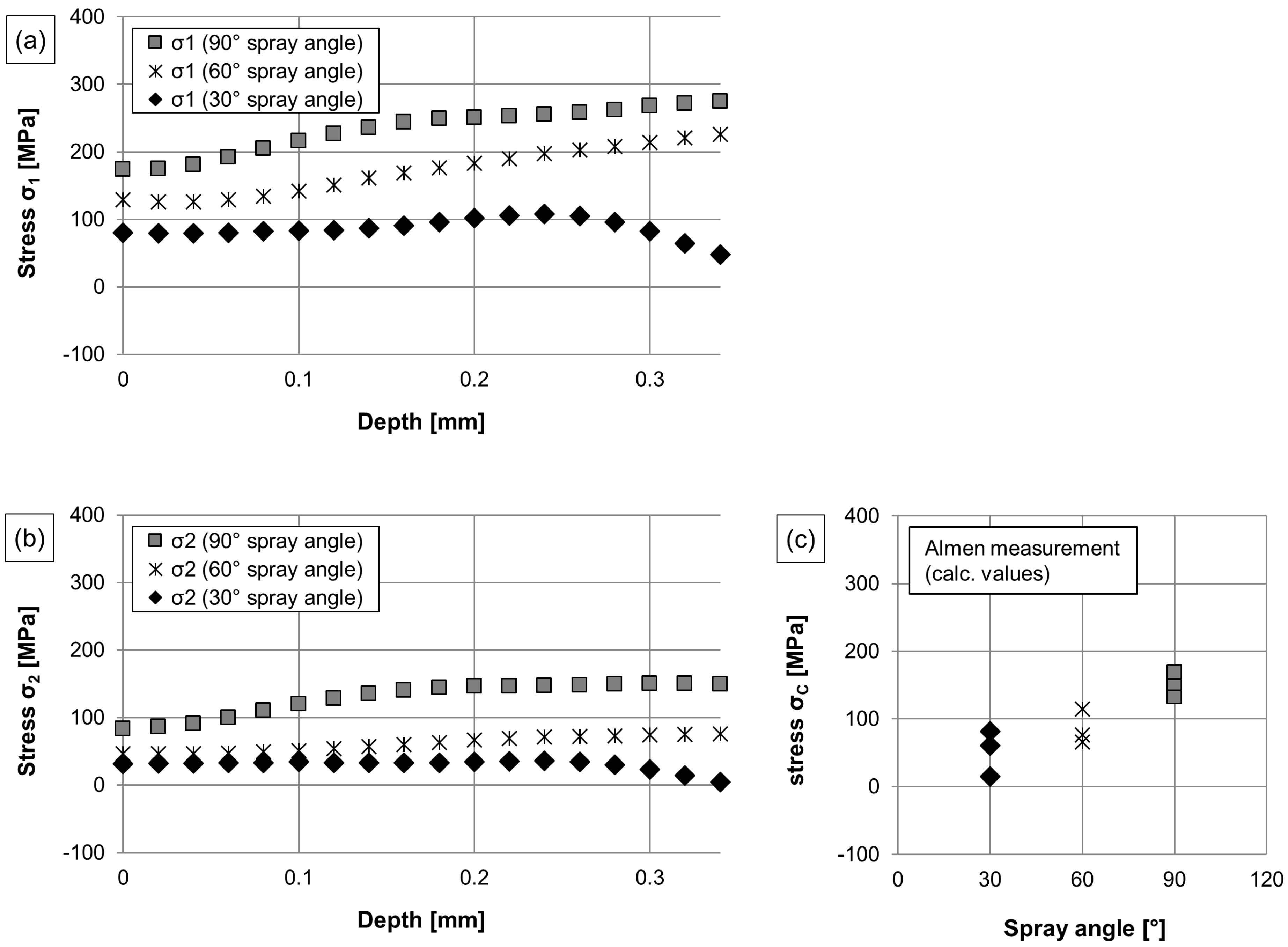
Figure 4.
Cross-section images taken by optical microscopy, showing the microstructure of the coating, deposited by using different spray angles: (a) 90°; (b) 60°; (c) 30°.
Figure 4.
Cross-section images taken by optical microscopy, showing the microstructure of the coating, deposited by using different spray angles: (a) 90°; (b) 60°; (c) 30°.

Figure 5.
Electron microscopy showing the splashing of spray particles deposited at different spray angles: (a) 90°; (b) 60°; (c) 30°.
Figure 5.
Electron microscopy showing the splashing of spray particles deposited at different spray angles: (a) 90°; (b) 60°; (c) 30°.
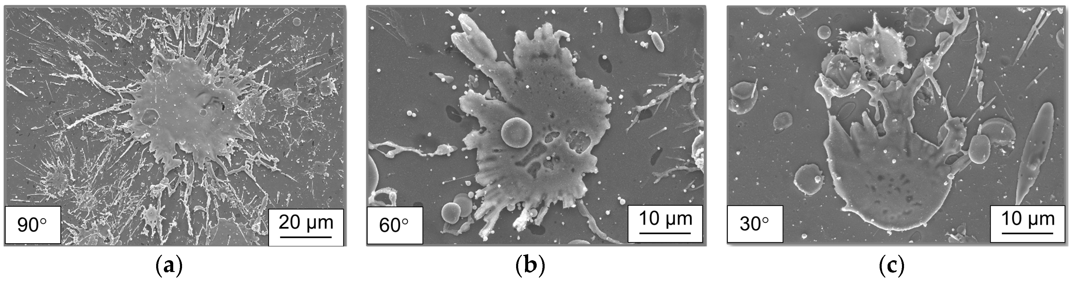
Figure 6.
Residual stress distribution along coatings produced with different preheating procedures, determined by using the bore hole drilling strain gage method (a,b), and calculated stress states in coatings produced with different preheating procedures using the curvature method (c).
Figure 6.
Residual stress distribution along coatings produced with different preheating procedures, determined by using the bore hole drilling strain gage method (a,b), and calculated stress states in coatings produced with different preheating procedures using the curvature method (c).

Figure 7.
Evolution of the temperature at the interface during spraying depending on the substrate preheating temperature.
Figure 7.
Evolution of the temperature at the interface during spraying depending on the substrate preheating temperature.

Figure 8.
Residual stress distribution along coatings produced with different gun velocities determined by using the bore hole drilling strain gage method (a,b) (coating thickness: 330 ± 19 µm, 261 ± 20 µm, and 182 ± 18 µm, for 12,000, 18,000, and 24,000 mm/min, respectively), and calculated stress state in coatings produced with different gun velocities using the curvature method (c).
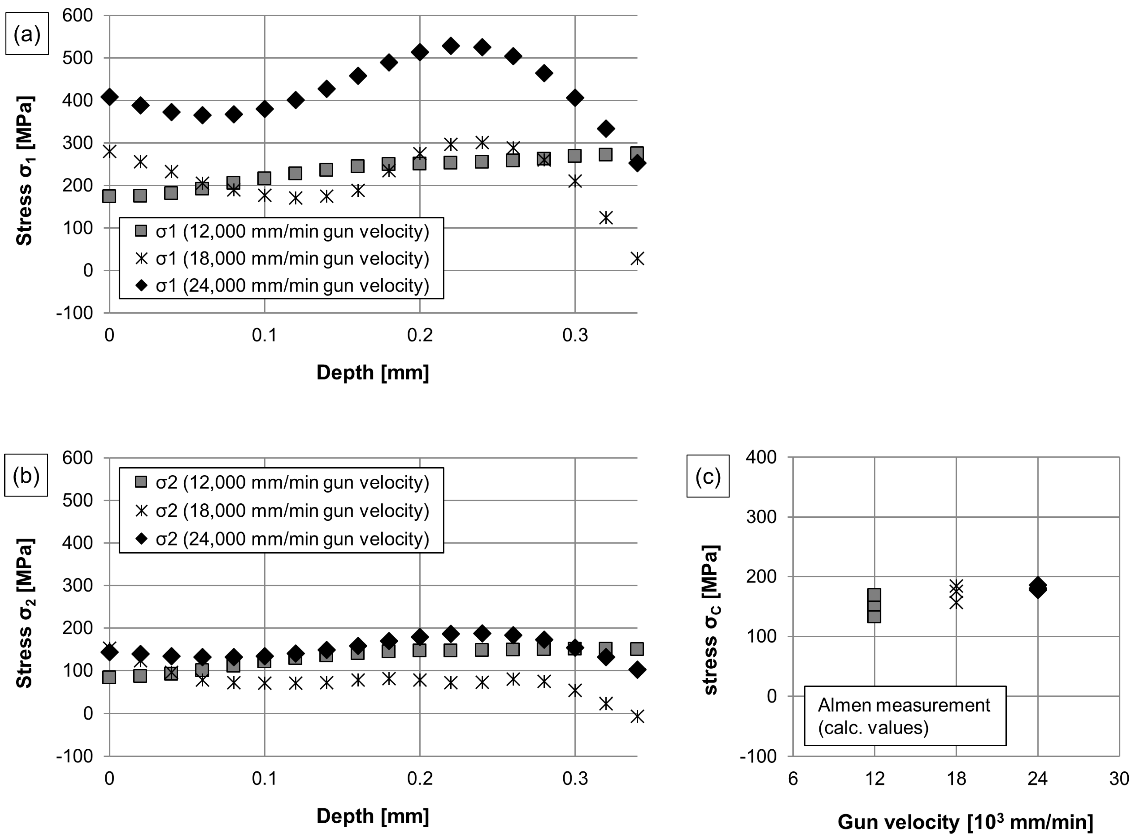
Figure 9.
Evaluation of the temperature at the interface during spraying depending on the gun velocity.
Figure 9.
Evaluation of the temperature at the interface during spraying depending on the gun velocity.
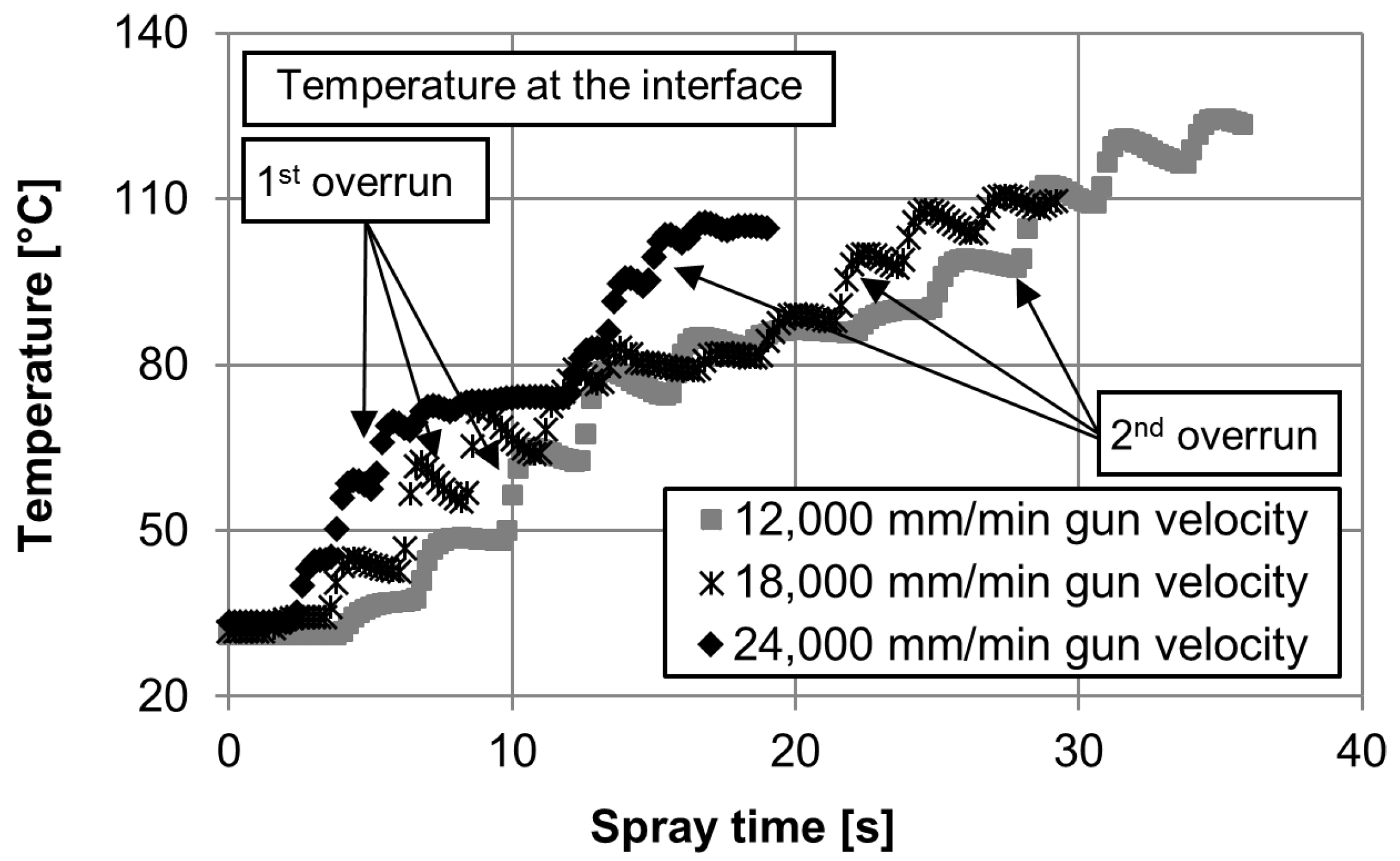
Figure 10.
Residual stress distribution along coatings produced with different PGP, determined by using the bore hole drilling strain gage method (a,b), and calculated stress states in coatings produced with different PGP using the curvature method (c).
Figure 10.
Residual stress distribution along coatings produced with different PGP, determined by using the bore hole drilling strain gage method (a,b), and calculated stress states in coatings produced with different PGP using the curvature method (c).

Figure 11.
Differential pressure flow measurement, showing the gas velocity measured at different axial positions.
Figure 11.
Differential pressure flow measurement, showing the gas velocity measured at different axial positions.

Table 1.
Process parameter settings.
| Parameter | Primary Gas Pressure (PGP) (Mpa) | Gun Velocity (mm/min) | Substrate Temperature (°C) | Spray Angle (°) |
|---|---|---|---|---|
| Gas velocity | 0.4 | 12,000 | RT | 90 |
| 0.6 | 12,000 | RT | 90 | |
| 0.8 | 12,000 | RT | 90 | |
| Deposition rate | 0.6 | 12,000 | RT | 90 |
| 0.6 | 18,000 | RT | 90 | |
| 0.6 | 24,000 | RT | 90 | |
| Preheating | 0.6 | 12,000 | RT | 90 |
| 0.6 | 12,000 | 150 | 90 | |
| 0.6 | 12,000 | 300 | 90 | |
| Spray angle | 0.6 | 12,000 | RT | 90 |
| 0.6 | 12,000 | RT | 60 | |
| 0.6 | 12,000 | RT | 30 |
Table 2.
Thermal and mechanical properties of the coating and substrate material.
| Material | Young’s Modulus E | Shear Modulus G | Poisson Ratio v |
|---|---|---|---|
| CTC-FeCMnSi | 55 GPa | 21.2 GPa | 0.3 |
| 1.0503 Steel | 190 GPa | 73.6 GPa | 0.29 |
© 2017 by the authors. Licensee MDPI, Basel, Switzerland. This article is an open access article distributed under the terms and conditions of the Creative Commons Attribution (CC BY) license (http://creativecommons.org/licenses/by/4.0/).
Share and Cite
MDPI and ACS Style
Tillmann, W.; Hagen, L.; Luo, W. Process Parameter Settings and Their Effect on Residual Stresses in WC/W2C Reinforced Iron-Based Arc Sprayed Coatings. Coatings 2017, 7, 125. https://doi.org/10.3390/coatings7080125
AMA Style
Tillmann W, Hagen L, Luo W. Process Parameter Settings and Their Effect on Residual Stresses in WC/W2C Reinforced Iron-Based Arc Sprayed Coatings. Coatings. 2017; 7(8):125. https://doi.org/10.3390/coatings7080125
Chicago/Turabian StyleTillmann, Wolfgang, Leif Hagen, and Weifeng Luo. 2017. "Process Parameter Settings and Their Effect on Residual Stresses in WC/W2C Reinforced Iron-Based Arc Sprayed Coatings" Coatings 7, no. 8: 125. https://doi.org/10.3390/coatings7080125
Note that from the first issue of 2016, this journal uses article numbers instead of page numbers. See further details here.