
Corrosion Protection Systems and Fatigue Corrosion in Offshore Wind Structures: Current Status and Future Perspectives


Abstract
:1. Introduction
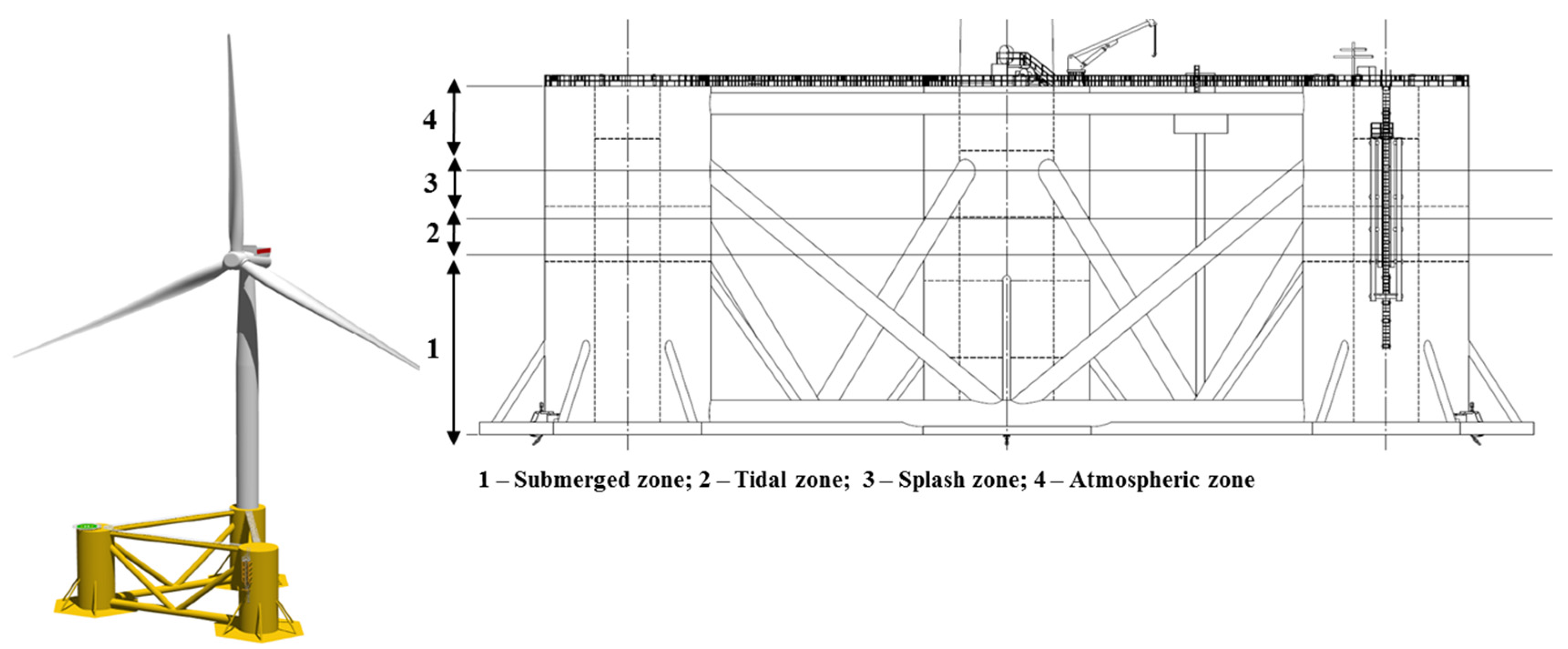
2. Offshore Wind Structures
2.1. Corrosion on OWS
- Uniform or general corrosion;
- Pitting corrosion;
- Crevice corrosion; filiform corrosion and poultice corrosion;
- Galvanic corrosion;
- Erosion-corrosion;
- Intergranular corrosion,
- Dealloying;
- Environmentally assisted cracking, including stress-corrosion cracking, corrosion fatigue and hydrogen damage.
- Operational assessment;
- Data acquisition;
- Information selection and condensation;
- Development of the statistical model.
2.2. Fatigue on OWS
- Material properties—thermal and mechanical treatments, internal structure, internal defects of the metallic base, welding defects, mechanical properties (yield and tensile strength) and the presence of residual stress.
- Geometry and properties of the element—shape, size, stiffness, type and geometry of connections, shear-lag, fabrication and assembling errors, etc.
- Environmental effects—including the temperature and corrosion effects.
- Loading—tension and/or compression, bending, shear, torsion, multiaxial loading, stress range, average stress, etc.
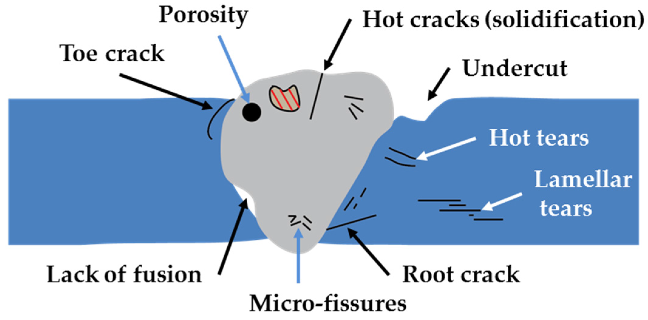
- Cracks are ruptures that generally occur in the weld or in the metallic base with slight apparent deformation. Three classes are generally recognized, namely: macro-fissure, cold and hot cracks;
- Undercut is a groove formed at the weld toe or weld root, or at the edge of a layer or a bead and it represents a stress concentration region. This problem is generally linked to the parameters of welding process and to poor execution.
- Lack of fusion is a discontinuity formed due to failure of fusion between the weld and the metallic base. This may occur due to the contamination of the surface or due to insufficient heating.
- Lack of penetration occurs when the weld metal fails to penetrate into the joint root due to inadequate joint design, improper electrode or low welding current.
- Porosity consists of the formation of cavities (discontinuities) due to gas entrapment during solidification of weld metal. Possible causes include lack of deoxidisers, high sulphur content of the metallic base, contamination of the surface and welding process parameters.
- Slag inclusions are non-metallic solid inclusions that are entrapped in the weld metal during welding. These, generally, arise from the composition of the materials used in the process of from the contamination of the weld metal. It may be minimized by suitable surface and groove preparation between successive steps.
- Micro-cracks resulting from the riveting process;
- Overlapping of shear and bending at cross sections with changes in geometry;
- Thin connection plates;
- Non-symmetrical details;
- Poor structural design resulting in high stress concentrations;
- Corroded bearings or joints;
- Secondary stresses;
- Distortion, restraint, out-of-plane bending;
- Local stress concentration, reduced detail category and cut outs.
- Poor weld or weld defects;
- Deficiency of fusion;
- Cold cracks;
- Vibration;
- Restraint;
- Geometrical changes;
- Repeated web buckling deformation.
3. Coating Systems
- Selection of the most suitable protective system according to the particular environmental conditions;
- Coating requirements;
- Assessment of the structure design to optimize coating system application;
- Detail clearly and unequivocally the specifications of the system;
- Use adequate and suitable techniques for coating deposition;
- Respect the requirements of the coating system;
- Rigorous quality control of the specified and supplied materials;
- Inspection at all phases during coating system application.
3.1. Coating Systems for OWS
3.2. Application Methods
3.2.1. Organic Coatings (Paints)
3.2.2. Metallic Coatings
3.3. Procedures—Previous Assessment, Selection of Coating Systems and Specifications
- Corrosivity of the environment—should be analysed in order to establish the specific conditions and stresses which may affect the selection of the coating system;
- Structure—should be previously examined and its design should be optimized;
- Condition of the surface—should be assessed;
- Coating system identification and selection for the required durability considering the environment and the method of surface preparation to be used;
- Minimize the risks of harmful effects to the environment, health and safety;
- Work plan where the application method is established;
- Inspection and maintenance plans—these should cover the whole service life of the structure.
3.4. Surface Preparation
3.5. Execution Conditions
- Technical qualification of personnel;
- Achievement of the quality level specified in each stage;
- Substrate requirements;
- Compliance with all health safety and environmental policies.
3.6. Quality Control
3.7. Health Safety and Environmental Regulations
- Protection of the body, including eyes, skin, ears and respiratory system;
- Protection against harmful effects of fumes, dust, vapours and noise as well as fire hazards;
- Protection of water and soil during coating application works;
- Low VOCs content products should be selected;
- Appropriate ventilation should be provided particularly in confined spaces;
- Recycling of materials and disposal of waste must be carried out.
4. Coating Performance and Assessment Techniques
4.1. Non-Destructive Methods (NDM)
4.1.1. Visual Inspection
- Number of inspections performed annually;
- Structure accessibility and complexity;
- Comfort to access heights;
- Visual acuity and colour vision;
- Luminosity during inspection;
- Time to complete the inspection;
- Inspector knowledge and experience level;
- The overall precision with which the inspectors carried out the inspection.
4.1.2. Foucault Current Inspection
4.1.3. Ultrasonic Methods (UM)
4.2. Destructive Methods (DM)
4.2.1. Corrosion Tests
4.2.1.1. Polarization Resistance (Rp)
4.2.1.2. Potentiodynamic Polarization Method (PPM)
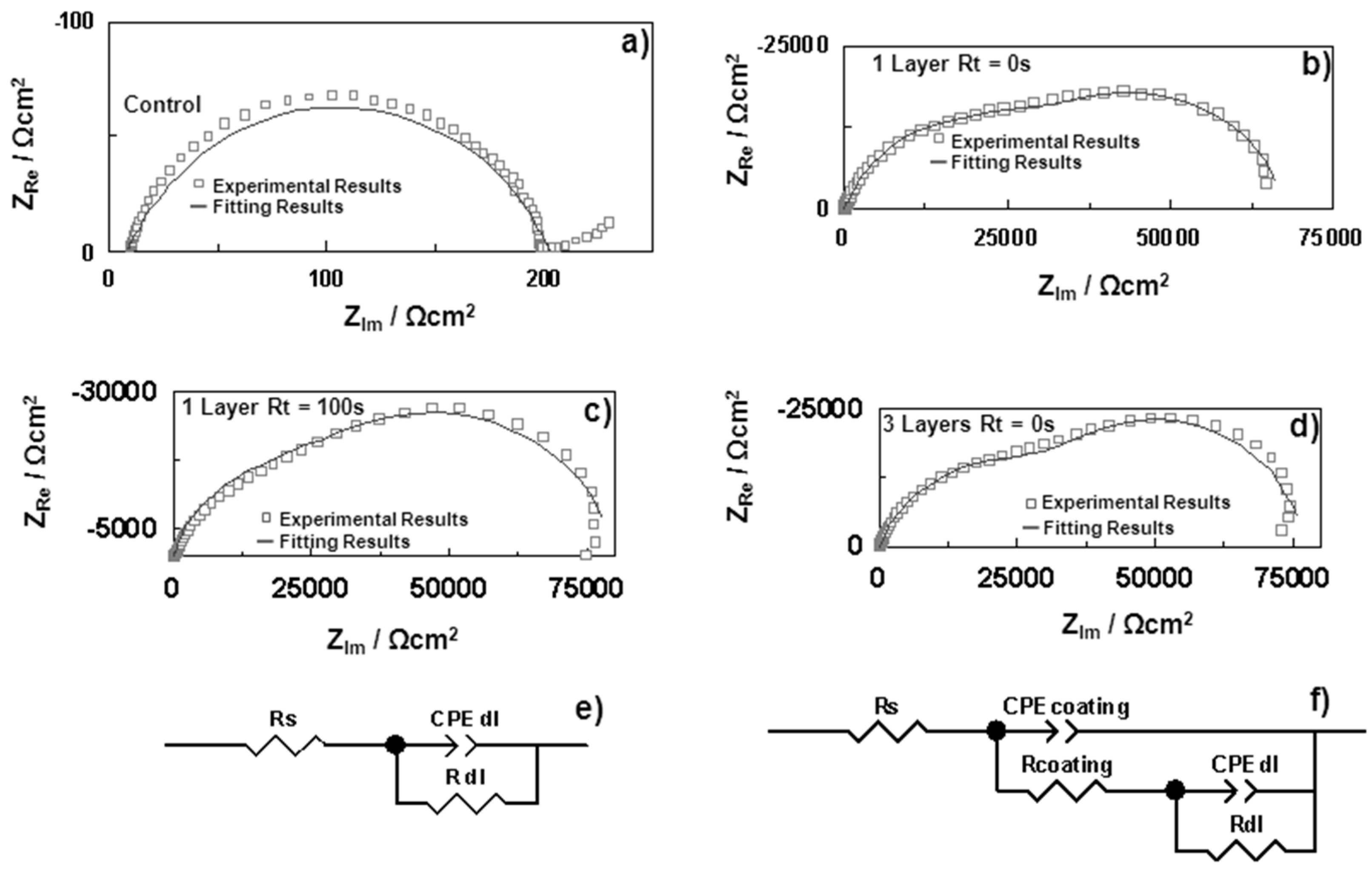
4.2.1.3. Electrochemical Impedance Spectroscopy Method (EIS)
4.2.2. Metallographic Tests
4.2.3. Chemical Analysis
4.3. Fatigue Assessment
- Damage tolerant method—this method is based on the proper performance of a structure during its service life with the implementation of adequate plans of inspection and maintenance. The structure may be considered reliable with the following conditions.
- Selection of materials, details and design, which, in case of crack initiation would result in a low rate of crack propagation and in a long critical crack length.
- Implementation of multiple load paths and details capable of arresting cracks that can be easily inspected during the planed inspections.
- Safe life method—this method is based on the proper performance of the structure without the need of regular inspections by providing an acceptable level of reliability. The reliability of the structure depends on selecting details and stress levels, which would result in enough fatigue life to achieve values equal to those for ultimate limit state verifications at the end of the design life.
4.3.1. Methods to Improve Fatigue Resistance
4.3.1.1. Grinding Methods
4.3.1.2. Peening Methods
- Shot peening—A machining operation that offers an extensive improvement in the fatigue strength of welded joints. The extent of improvement is dependent on the type of joint and the yield strength of the materials. Shot peening consists of driving the shot (round metallic, glass or ceramic particles), at high velocity, against the area to be treated producing a compressive residual stress in the order of 70%–80% of the yield stress. The shot size is approximately 0.2–1.0 mm depending on the undercuts and interpass notches. The projection velocity should range between 40–60 m·s−1 [214].
- Hammer peening—A manual technique that decreases the stress concertation at the weld toe by generating a large amount of cold work and changing the radius and angle of the weld toe.
- Ultrasonic impact peening (UIP)—A recently developed technique that uses an ultrasonic hammer to treat the area along the weld toe. A similar mechanism to hammer peening takes place. UIP consists in a single pass of the ultrasonic hammer along the weld toe with a velocity of 0.5 m·s−1. To produce significant compressive residual stresses, an approximate depth of 0.5–0.7 mm should be achieved.
- Needle peening—Is a technique that is also similar to hammer peening though instead of a solid tool a group of steel wires is used [214].
5. Future Perspectives
6. Conclusions
- Protective coatings and/or cathodic protection;
- Use of a corrosion allowance;
- Inspection/monitoring of corrosion;
- Corrosion-protection-friendly design;
- Control of environment.
Acknowledgments
Conflicts of Interest
References
- Martinez-Luengo, M.; Kolios, A.; Wang, L. Structural health monitoring of offshore wind turbines: A review through the Statistical Pattern Recognition Paradigm. Renew. Sustain. Energy Rev. 2016, 64, 91–105. [Google Scholar] [CrossRef] [Green Version]
- European Comission Earto—Recommendations for Future EU Polies 2014. Available online: http://www.earto.eu/fileadmin/content/04_Newsletter/Newsletter_5_2014/EARTO_Recommendations_for_Future_EU_Innovation_Policy_-_2014.pdf (accessed on 22 April 2016).
- González, J.S.; Lacal-Arántegui, R. A review of regulatory framework for wind energy in European Union countries: Current state and expected developments. Renew. Sustain. Energy Rev. 2016, 56, 588–602. [Google Scholar] [CrossRef]
- Colmenar-Santos, A.; Perera-Perez, J.; Borge-Diez, D.; de Palacio-Rodríguez, C. Offshore wind energy: A review of the current status, challenges and future development in Spain. Renew. Sustain. Energy Rev. 2016, 64, 1–18. [Google Scholar] [CrossRef]
- EWEA (The European Wind Energy Association). The European Offshore Wind Industry—Key Trends and Statistics 2011; Technical Report; EWEA: Bruxelles, Belgium, 2012. [Google Scholar]
- EWEA (The European Wind Energy Association). The European Offshore Wind Industry—Key Trends and Statistics 2012; Technical Report; EWEA: Bruxelles, Belgium, 2013. [Google Scholar]
- EWEA (The European Wind Energy Association). The European Offshore Wind Industry—Key Trends and Statistics 2013; Technical Report; EWEA: Bruxelles, Belgium, 2014. [Google Scholar]
- EWEA (The European Wind Energy Association). The European Offshore Wind Industry—Key Trends and Statistics 2014; Technical Report; EWEA: Bruxelles, Belgium, 2015. [Google Scholar]
- EWEA (The European Wind Energy Association). The European Offshore Wind Industry—Key Trends and Statistics 2015; Technical Report; EWEA: Bruxelles, Belgium, 2016. [Google Scholar]
- Higgins, P.; Foley, A. The evolution of offshore wind power in the United Kingdom. Renew. Sustain. Energy Rev. 2014, 37, 599–612. [Google Scholar] [CrossRef]
- Castro-Santos, L.; Diaz-Casas, V. Sensitivity analysis of floating offshore wind farms. Energy Convers. Manag. 2015, 101, 271–277. [Google Scholar] [CrossRef]
- Rodrigues, S.; Restrepo, C.; Kontos, E.; Teixeira, P.R.; Bauer, P. Trends of offshore wind projects. Renew. Sustain. Energy Rev. 2015, 49, 1114–1135. [Google Scholar] [CrossRef]
- Levitt, A.C.; Kempton, W.; Smith, A.P.; Musial, W.; Firestone, J. Pricing offshore wind power. Energy Policy 2011, 39, 6408–6421. [Google Scholar] [CrossRef]
- Myhr, A.; Bjerkseter, C.; Ågotnes, A.; Nygaard, T.A. Levelised cost of energy for offshore floating wind turbines in a life cycle perspective. Renew. Energy 2014, 66, 714–728. [Google Scholar] [CrossRef]
- Jonkman, J.M.; Matha, D. Dynamics of offshore floating wind turbines—Analysis of three concepts. Wind Energy 2011, 14, 557–569. [Google Scholar] [CrossRef]
- Chen, L.; MacDonald, E. A system-level cost-of-energy wind farm layout optimization with landowner modeling. Energy Convers. Manag. 2014, 77, 484–494. [Google Scholar] [CrossRef]
- Castro-Santos, L.; Diaz-Casas, V. Floating Offshore Wind Farms. In Green Energy and Technology; Springer International Publishing: Cham, Switzerland, 2016. [Google Scholar]
- Cruz, J.; Atcheson, M. Floating Offshore Wind Energy. In Green Energy and Technology; Springer International Publishing: Cham, Switzerland, 2016. [Google Scholar]
- Roddier, D.; Cermelli, C.; Aubault, A.; Weinstein, A. WindFloat: A floating foundation for offshore wind turbines. J. Renew. Sustain. Energy 2010, 2, 33104. [Google Scholar] [CrossRef]
- Cermelli, C.; Roddier, D.; Aubault, A. WindFloat: A Floating Foundation for Offshore Wind Turbines—Part II: Hydrodynamics Analysis. In Proceedings of the ASME 2009 28th International Conference on Ocean, Offshore and Arctic Engineering, Honolulu, HI, USA, 31 May–5 June 2009; pp. 135–143.
- Aubault, A.; Cermelli, C.; Roddier, D. Parametric Optimization of a Semi-Submersible Platform with Heave Plates. In Proceedings of the ASME 2007 26th International Conference on Offshore Mechanics and Arctic Engineering, San Diego, CA, USA, 10–15 June 2007; pp. 471–478.
- Principle Power, Inc.—Globalizing Offshore Wind. Available online: http://www.principlepowerinc.com/ (accessed on 10 October 2016).
- Study to Feasibility of Boundary Conditions for Floating Offshore Wind Turbines. Available online: https://www.researchgate.net/publication/260432811_Study_to_feasibility_of_and_boundary_conditionsfor_floating_offshore_wind_turbines (accessed on 4 February 2017).
- Portail des Energies de la Mer—Energies de la Mer. Available online: http://www.energiesdelamer.eu/ (accessed on 10 October 2016).
- Accueil—Nenuphar Wind. Available online: http://www.nenuphar-wind.com/fr/ (accessed on 10 October 2016).
- WindSea AS—Home. Available online: http://www.windsea.no/ (accessed on 10 October 2016).
- Lee, K.H. Responses of Floating Wind Turbines to Wind and Wave Excitation. Ph.D. Thesis, Massachusetts Institute of Technology, Cambridge, MA, USA, 2005. [Google Scholar]
- Pôle Mer Bretagne Atlantique. Available online: http://www.pole-mer-bretagne-atlantique.com/fr/ (accessed on 10 October 2016).
- Offshore-Windenergie: Fachliche und Technische Herausforderungen: GICON—Großmann Ingenieur Consult GmbH. Available online: http://www.gicon.de/publikationen/fachveroeffentlichungen/veroeffentlichungen/offshore-windenergie-fachliche-und-technische-herausforderungen.html (accessed on 10 October 2016).
- Statoil—A Leading Energy Company in Oil and Gas Production. Available online: http://www.statoil.com/en/Pages/default.aspx (accessed on 10 October 2016).
- Njord Floating Wind Power Platform AS|NordicGreen—Nordic Cleantech Scandinavia Startups. Available online: http://www.nordicgreen.net/startups/wind/njord-floating-wind-power-platform (accessed on 10 October 2016).
- Sway|Changing the Future of Wind Power. Available online: http://www.sway.no/ (accessed on 10 October 2016).
- A Tribute to Floating Windfarms Corporation. Available online: http://floatingwindfarms.com/index.html (accessed on 10 October 2016).
- Momber, A. Corrosion and corrosion protection of support structures for offshore wind energy devices (OWEA). Mater. Corros. 2011, 62, 391–404. [Google Scholar] [CrossRef]
- Momber, A.W.; Plagemann, P.; Stenzel, V.; Schneider, M. Investigating Corrosion Protection of Offshore Wind Towers: Part 1: Background and Test Program. J. Prot. Coat. Linings 2008, 30, 1–14. [Google Scholar]
- Momber, A.W.; Plagemann, P.; Stenzel, V. The adhesion of corrosion protection coating systems for offshore wind power constructions after three years under offshore exposure. Int. J. Adhes. Adhes. 2016, 65, 96–101. [Google Scholar] [CrossRef]
- Mühlberg, K. Corrosion Protection of Offshore Wind Turbines-a Challenge for the Steel Builder and Paint Applicator. J. Prot. Coat. Linings 2010, 20, 20–27. [Google Scholar]
- Adedipe, O.; Brennan, F.; Kolios, A. Review of corrosion fatigue in offshore structures: Present status and challenges in the offshore wind sector. Renew. Sustain. Energy Rev. 2016, 61, 141–154. [Google Scholar] [CrossRef]
- Dong, W.; Moan, T.; Gao, Z. Fatigue reliability analysis of the jacket support structure for offshore wind turbine considering the effect of corrosion and inspection. Reliab. Eng. Syst. Saf. 2012, 106, 11–27. [Google Scholar] [CrossRef]
- Bernhammer, L.O.; van Kuik, G.A.M.; De Breuker, R. Fatigue and extreme load reduction of wind turbine components using smart rotors. J. Wind Eng. Ind. Aerodyn. 2016, 154, 84–95. [Google Scholar] [CrossRef]
- Chew, K.-H.; Tai, K.; Ng, E.Y.K.; Muskulus, M. Analytical gradient-based optimization of offshore wind turbine substructures under fatigue and extreme loads. Mar. Struct. 2016, 47, 23–41. [Google Scholar] [CrossRef] [Green Version]
- Gallego-Calderon, J.; Natarajan, A. Assessment of wind turbine drive-train fatigue loads under torsional excitation. Eng. Struct. 2015, 103, 189–202. [Google Scholar] [CrossRef]
- Herrmann, J.; Rauert, T.; Dalhoff, P.; Sander, M. Fatigue and fracture mechanical behaviour of a wind turbine rotor shaft made of cast iron and forged steel. Procedia Struct. Integr. 2016, 2, 2951–2958. [Google Scholar] [CrossRef]
- Jang, Y.J.; Choi, C.W.; Lee, J.H.; Kang, K.W. Development of fatigue life prediction method and effect of 10-minute mean wind speed distribution on fatigue life of small wind turbine composite blade. Renew. Energy 2015, 79, 187–198. [Google Scholar] [CrossRef]
- Koukoura, C.; Brown, C.; Natarajan, A.; Vesth, A. Cross-wind fatigue analysis of a full scale offshore wind turbine in the case of wind–wave misalignment. Eng. Struct. 2016, 120, 147–157. [Google Scholar] [CrossRef] [Green Version]
- Lee, H.G.; Kang, M.G.; Park, J. Fatigue failure of a composite wind turbine blade at its root end. Compos. Struct. 2015, 133, 878–885. [Google Scholar] [CrossRef]
- Lee, H.G.; Park, J. Static test until structural collapse after fatigue testing of a full-scale wind turbine blade. Compos. Struct. 2016, 136, 251–257. [Google Scholar] [CrossRef]
- Liu, X.; Bo, L.; Luo, H. Dynamical measurement system for wind turbine fatigue load. Renew. Energy 2016, 86, 909–921. [Google Scholar] [CrossRef]
- Nejad, A.R.; Bachynski, E.E.; Kvittem, M.I.; Luan, C.; Gao, Z.; Moan, T. Stochastic dynamic load effect and fatigue damage analysis of drivetrains in land-based and TLP, spar and semi-submersible floating wind turbines. Mar. Struct. 2015, 42, 137–153. [Google Scholar] [CrossRef]
- Tande, J.O.G.; Kvamsdal, T.; Muskulus, M.; Kelma, S.; Schaumann, P. Probabilistic Fatigue Analysis of Jacket Support Structures for Offshore Wind Turbines Exemplified on Tubular Joints. Energy Procedia 2015, 80, 151–158. [Google Scholar]
- Toft, H.S.; Svenningsen, L.; Sørensen, J.D.; Moser, W.; Thøgersen, M.L. Uncertainty in wind climate parameters and their influence on wind turbine fatigue loads. Renew. Energy 2016, 90, 352–361. [Google Scholar] [CrossRef]
- Yeter, B.; Garbatov, Y.; Guedes, S.C. Fatigue damage assessment of fixed offshore wind turbine tripod support structures. Eng. Struct. 2015, 101, 518–528. [Google Scholar] [CrossRef]
- Zhang, M.; Tan, B.; Xu, J. Smart fatigue load control on the large-scale wind turbine blades using different sensing signals. Renew. Energy 2016, 87(Part 1), 111–119. [Google Scholar] [CrossRef]
- Ziegler, L.; Voormeeren, S.; Schafhirt, S.; Muskulus, M. Design clustering of offshore wind turbines using probabilistic fatigue load estimation. Renew. Energy 2016, 91, 425–433. [Google Scholar] [CrossRef]
- Wymore, M.L.; Van Dam, J.E.; Ceylan, H.; Qiao, D. A survey of health monitoring systems for wind turbines. Renew. Sustain. Energy Rev. 2015, 52, 976–990. [Google Scholar] [CrossRef]
- Tajari, M.; Azarsina, F.; Ashrafi, K.N. Nonlinear statics analysis of on offshore jaket platform in the case of explosion. Int. J. Mar. Sci. Eng. 2013, 3, 33–42. [Google Scholar]
- Bertelsen, K.; Erichsen, H.V.; Madsen, S.F. New high current test principle for wind turbine blades simulating the life time impact from lightning discharges. In Proceedings of the International Conference on Lightning and Static Electricity, Paris, France, 28–31 August 2007.
- Gao, L. Characteristics of Streamer Discharges in Air and Along Insulating Surfaces. Ph.D. Thesis, Comprehensive Summaries of Uppsala Dissertations from the Faculty of Science and Technology, University of Uppsala, Uppsala, Sweden, 2000. [Google Scholar]
- Rafiei, R.; Mohseni, M.; Yari, H.; Mahdavi, M. Evaluation of degradability of two polyurethane refinish coatings against biological materials: A case study. Prog. Org. Coat. 2016, 93, 1–10. [Google Scholar] [CrossRef]
- Ramezanzadeh, B.; Mohseni, M.; Yari, H. On the electrochemical and structural behaviour of biologically degraded automotive coatings; Part 1: Effect of natural and simulated bird droppings. Prog. Org. Coat. 2011, 71, 19–31. [Google Scholar] [CrossRef]
- Ramezanzadeh, B.; Mohseni, M.; Yari, H.; Sabbaghian, S. An evaluation of an automotive clear coat performance exposed to bird droppings under different testing approaches. Prog. Org. Coat. 2009, 66, 149–160. [Google Scholar] [CrossRef]
- Momber, A.W.; Plagemann, P.; Stenzel, V. Performance and integrity of protective coating systems for offshore wind power structures after three years under offshore site conditions. Renew. Energy 2015, 74, 606–617. [Google Scholar] [CrossRef]
- Adedipe, O.; Brennan, F.; Kolios, A. Corrosion fatigue load frequency sensitivity analysis. Mar. Struct. 2015, 42, 115–136. [Google Scholar] [CrossRef]
- DNVGL-OS-C401. Fabrication and Testing of Offshore Structures; DNV GL–Energy: Arnhem, The Netherlands, 2010. [Google Scholar]
- DNV-OS-J101. Design of Offshore Wind Turbine Structures; DNV GL–Energy: Arnhem, The Netherlands, 2014. [Google Scholar]
- DNV-OS-J201. Offshore Substations for Wind Farms; DNV GL–Energy: Arnhem, The Netherlands, 2009. [Google Scholar]
- Soares, C.G.; Shenoi, R.A. Seatracker Analysis and Design of Marine Structures; CRC Press: Boca Raton, FL, USA, 2015. [Google Scholar]
- Davis, J.R. Corrosion Understanding the Basics; ASM International: Materials Park, OH, USA, 2000. [Google Scholar]
- Beech, I.B.; Sunner, J. Biocorrosion: Towards understanding interactions between biofilms and metals. Curr. Opin. Biotechnol. 2004, 15, 181–186. [Google Scholar] [CrossRef] [PubMed]
- Almeida, E.; Diamantino, T.C.; de Sousa, O. Marine paints: The particular case of antifouling paints. Prog. Org. Coat. 2007, 59, 2–20. [Google Scholar] [CrossRef]
- ISO 12944-5:2007. Paints and Varnishes—Corrosion Protection of Steel Structures by Protective Paint Systems—Part 5: Protective Paint Systems; ISO: Geneva, Switzerland, 2007. [Google Scholar]
- Ault, J.P. The use of coatings for corrosion control on offshore oil structures. J. Prot. Coat. Linings 2006, 23, 42–47. [Google Scholar]
- DNV–OS-C101. Design of Offshore Steel Structures, General (LRFD Method); DNV GL–Energy: Arnhem, The Netherlands, 2011. [Google Scholar]
- Momber, A.W. Quantitative performance assessment of corrosion protection systems for offshore wind power transmission platforms. Renew. Energy 2016, 94, 314–327. [Google Scholar] [CrossRef]
- Farrar, C.R.; Worden, K. An introduction to structural health monitoring. Philos. Trans. R. Soc. Lond. Math. Phys. Eng. Sci. 2007, 365, 303–315. [Google Scholar] [CrossRef] [PubMed]
- Farrar, C.R.; Worden, K. Index. In Structural Health Monitoring; John Wiley & Sons, Ltd.: New York, NY, USA, 2012; pp. 623–631. [Google Scholar]
- Worden, K.; Cross, E.J.; Dervilis, N.; Papatheou, E.; Antoniadou, I. Structural Health Monitoring: From Structures to Systems-of-Systems. IFAC Pap. 2015, 48, 1–17. [Google Scholar] [CrossRef]
- BS 499-1:2009. Welding Terms and Symbols. Glossary for Welding, Brazing and Thermal Cutting; BSI: London, UK, 2009. [Google Scholar]
- ISO 5817:2014. Welding—Fusion-Welded Joints in Steel, Nickel, Titanium and Their Alloys (Beam Welding Excluded)—Quality Levels for Imperfections; ISO (the International Organization for Standardization.): Geneva, Switzerland, 2014. [Google Scholar]
- Yusof, F.; Jamaluddin, M.F. 6.07—Welding Defects and Implications on Welded Assemblies A2—Hashmi, Saleem. In Comprehensive Materials Processing; Batalha, G.F., Tyne, C.J.V., Yilbas, B., Eds.; Elsevier: Oxford, UK, 2014; pp. 125–134. [Google Scholar]
- Kühn, B. Assessment of Existing Steel Structures—Recommendations for Estimation of the Remaining Fatigue Life. Procedia Eng. 2013, 66, 3–11. [Google Scholar] [CrossRef]
- Eurocodes: Building the Future—The European Commission Website on the Eurocodes. Available online: http://eurocodes.jrc.ec.europa.eu/showpublication.php?id=137 (accessed on 19 December 2016).
- Blondeau, R. Metallurgy and Mechanics of Welding; John Wiley & Sons: New York, NY, USA, 2013. [Google Scholar]
- Chandler, K.A.; Bayliss, D.A. Corrosion Protection of Steel Structures; Elsevier Applied Science Publishers: Amsterdam, The Netherlands, 1985. [Google Scholar]
- Lyon, S.B.; Bingham, R.; Mills, D.J. Advances in corrosion protection by organic coatings: What we know and what we would like to know. Prog. Org. Coat. 2017, 102(Part A), 2–7. [Google Scholar] [CrossRef]
- Detty, M.R.; Ciriminna, R.; Bright, F.V.; Pagliaro, M. Xerogel Coatings Produced by the Sol–Gel Process as Anti-Fouling, Fouling-Release Surfaces: From Lab Bench to Commercial Reality. ChemNanoMat 2015, 1, 148–154. [Google Scholar] [CrossRef]
- Trentin, I.; Romairone, V.; Marcenaro, G.; De Carolis, G. Quick test methods for marine antifouling paints. Prog. Org. Coat. 2001, 42, 15–19. [Google Scholar] [CrossRef]
- Detty, M.R.; Ciriminna, R.; Bright, F.V.; Pagliaro, M. Environmentally benign sol-gel antifouling and foul-releasing coatings. Acc. Chem. Res. 2014, 47, 678–687. [Google Scholar] [CrossRef] [PubMed]
- Azemar, F.; Faÿ, F.; Réhel, K.; Linossier, I. Development of hybrid antifouling paints. Prog. Org. Coat. 2015, 87, 10–19. [Google Scholar] [CrossRef]
- Carteau, D.; Vallée-Réhel, K.; Linossier, I.; Quiniou, F.; Davy, R.; Compère, C.; Delbury, M.; Faÿ, F. Development of environmentally friendly antifouling paints using biodegradable polymer and lower toxic substances. Prog. Org. Coat. 2014, 77, 485–493. [Google Scholar] [CrossRef]
- Palanichamy, S.; Subramanian, G. Antifouling properties of marine bacteriocin incorporated epoxy based paint. Prog. Org. Coat. 2017, 103, 33–39. [Google Scholar] [CrossRef]
- Faÿ, F.; Linossier, I.; Peron, J.J.; Langlois, V.; Vallée-Rehel, K. Antifouling activity of marine paints: Study of erosion. Prog. Org. Coat. 2007, 60, 194–206. [Google Scholar] [CrossRef]
- Buskens, P.; Wouters, M.; Rentrop, C.; Vroon, Z. A brief review of environmentally benign antifouling and foul-release coatings for marine applications. J. Coat. Technol. Res. 2013, 10, 29–36. [Google Scholar] [CrossRef]
- Telegdi, J.; Trif, L.; Románszki, L. 5—Smart anti-biofouling composite coatings for naval applications A2. In Smart Composite Coatings and Membranes; Woodhead Publishing Series in Composites Science and Engineering; Montemor, M.F., Ed.; Woodhead Publishing: Cambridge, UK, 2016; pp. 123–155. [Google Scholar]
- Torabinejad, V.; Aliofkhazraei, M.; Assareh, S.; Allahyarzadeh, M.H.; Rouhaghdam, A.S. Electrodeposition of Ni-Fe alloys, composites, and nano coatings–A review. J. Alloys Compd. 2017, 691, 841–859. [Google Scholar] [CrossRef]
- Gibson, A.G.; Arun, S. Composite Materials in the Offshore Industry. In Reference Module in Materials Science and Materials Engineering; Elsevier: Amsterdam, The Netherlands, 2016. [Google Scholar]
- Cho, S.H.; White, S.R.; Braun, P.V. Self-Healing Polymer Coatings. Adv. Mater. 2009, 21, 645–649. [Google Scholar] [CrossRef]
- Carneiro, J.; Tedim, J.; Fernandes, S.C.M.; Freire, C.S.R.; Silvestre, A.J.D.; Gandini, A.; Ferreira, M.G.S.; Zheludkevich, M.L. Chitosan-based self-healing protective coatings doped with cerium nitrate for corrosion protection of aluminum alloy 2024. Prog. Org. Coat. 2012, 75, 8–13. [Google Scholar] [CrossRef]
- Yoganandan, G.; Pradeep, P.K.; Balaraju, J.N. Evaluation of corrosion resistance and self-healing behavior of zirconium–cerium conversion coating developed on AA2024 alloy. Surf. Coat. Technol. 2015, 270, 249–258. [Google Scholar] [CrossRef]
- Lutz, A.; Mol, J.M.C.; De Graeve, I.; Terryn, H. 6—Smart corrosion protection by multi-action self-healing polymeric coatings A2. In Smart Composite Coatings and Membranes; Woodhead Publishing Series in Composites Science and Engineering; Montemor, M.F., Ed.; Woodhead Publishing: Cambridge, UK, 2016; pp. 157–181. [Google Scholar]
- Alaneme, K.K.; Bodunrin, M.O. Self-healing using metallic material systems—A review. Appl. Mater. Today 2017, 6, 9–15. [Google Scholar] [CrossRef]
- Montemor, M.F. Hybrid nanocontainer-based smart self-healing composite coatings for the protection of metallic assets. In Smart Composite Coatings and Membranes; Woodhead Publishing Series in Composites Science and Engineering; Meng, H., Ed.; Woodhead Publishing: Cambridge, UK, 2016; pp. 183–209. [Google Scholar]
- Hughes, A.E. Self-healing coatings A2. In Recent Advances in Smart Self-healing Polymers and Composites; Woodhead Publishing Series in Composites Science and Engineering; Li, G.Q., Ed.; Woodhead Publishing: Cambridge, UK, 2015; pp. 211–241. [Google Scholar]
- Montemor, M.F. Functional and smart coatings for corrosion protection: A review of recent advances. Surf. Coat. Technol. 2014, 258, 17–37. [Google Scholar] [CrossRef]
- Plawecka, M.; Snihirova, D.; Martins, B.; Szczepanowicz, K.; Warszynski, P.; Montemor, M.F. Self healing ability of inhibitor-containing nanocapsules loaded in epoxy coatings applied on aluminium 5083 and galvanneal substrates. Electrochim. Acta 2014, 140, 282–293. [Google Scholar] [CrossRef]
- Mittal, V. Self-healing anti-corrosion coatings for applications in structural and petrochemical engineering A2. In Handbook of Smart Coatings for Materials Protection; Makhlouf, A.S.H., Ed.; Woodhead Publishing: Cambridge, UK, 2014; pp. 183–197. [Google Scholar]
- Thakur, V.K.; Kessler, M.R. Self-healing polymer nanocomposite materials: A review. Polymer 2015, 69, 369–383. [Google Scholar] [CrossRef]
- Figueira, R.B.; Fontinha, I.R.; Silva, C.J.R.; Pereira, E.V. Hybrid Sol-Gel Coatings: Smart and Green Materials for Corrosion Mitigation. Coatings 2016, 6, 12. [Google Scholar] [CrossRef]
- Pandey, S.; Mishra, S.B. Sol–gel derived organic–inorganic hybrid materials: Synthesis, characterizations and applications. J. Sol-Gel Sci. Technol. 2011, 59, 73–94. [Google Scholar] [CrossRef]
- Han, Y.-H.; Taylor, A.; Mantle, M.D.; Knowles, K.M. UV curing of organic–inorganic hybrid coating materials. J. Sol-Gel Sci. Technol. 2007, 43, 111–123. [Google Scholar] [CrossRef]
- Gilberts, J.; Tinnemans, A.H.A.; Hogerheide, M.P.; Koster, T.P.M. UV Curable Hard Transparent Hybrid Coating Materials on Polycarbonate Prepared by the Sol-Gel Method. J. Sol-Gel Sci. Technol. 1998, 11, 153–159. [Google Scholar] [CrossRef]
- Sayilkan, H.; Şener, Ş.; Şener, E. The Sol-Gel Synthesis and Application of Some Anticorrosive Coating Materials. Mater. Sci. 2003, 39, 106–110. [Google Scholar] [CrossRef]
- Ciriminna, R.; Fidalgo, A.; Pandarus, V.; Béland, F.; Ilharco, L.M.; Pagliaro, M. The Sol-Gel Route to Advanced Silica-Based Materials and Recent Applications. Chem. Rev. 2013, 113, 6592–6620. [Google Scholar] [CrossRef] [PubMed]
- Wilkes, G.L.; Orler, B.; Huang, H.H. “Ceramers”: Hybrid materials incorporating polymeric/oligomeric species into inorganic glasses utilizing a sol-gel approach. Polym. Prep. 1985, 26, 300–302. [Google Scholar]
- Arkhireeva, A.; Hay, J.N.; Lane, J.M.; Manzano, M.; Masters, H.; Oware, W.; Shaw, S.J. Synthesis of Organic-Inorganic Hybrid Particles by Sol-Gel Chemistry. J. Sol-Gel Sci. Technol. 2004, 31, 31–36. [Google Scholar] [CrossRef]
- Innocenzi, P.; Kidchob, T.; Yoko, T. Hybrid Organic-Inorganic Sol-Gel Materials Based on Epoxy-Amine Systems. J. Sol-Gel Sci. Technol. 2005, 35, 225–235. [Google Scholar] [CrossRef]
- Figueira, R.B.; Silva, C.J.R.; Pereira, E.V. Organic–inorganic hybrid sol–gel coatings for metal corrosion protection: A review of recent progress. J. Coat. Technol. Res. 2014, 12, 1–35. [Google Scholar] [CrossRef]
- Figueira, R.B.; Silva, C.J.R.; Pereira, E.V. Hybrid sol–gel coatings for corrosion protection of hot-dip galvanized steel in alkaline medium. Surf. Coat. Technol. 2015, 265, 191–204. [Google Scholar] [CrossRef]
- Figueira, R.B.; Silva, C.J.; Pereira, E.V.; Salta, M.M. Alcohol-Aminosilicate Hybrid Coatings for Corrosion Protection of Galvanized Steel in Mortar. J. Electrochem. Soc. 2014, 161, C349–C362. [Google Scholar] [CrossRef]
- Carneiro, J.; Tedim, J.; Ferreira, M.G.S. Chitosan as a smart coating for corrosion protection of aluminum alloy 2024: A review. Prog. Org. Coat. 2015, 89, 348–356. [Google Scholar] [CrossRef]
- Dias, S.A.S.; Lamaka, S.V.; Nogueira, C.A.; Diamantino, T.C.; Ferreira, M.G.S. Sol–gel coatings modified with zeolite fillers for active corrosion protection of AA2024. Corros. Sci. 2012, 62, 153–162. [Google Scholar] [CrossRef]
- Mai, T. Technology Readiness Level. Available online: http://www.nasa.gov/directorates/heo/scan/engineering/technology/txt_accordion1.html (accessed on 9 January 2017).
- Frei, R.; McWilliam, R.; Derrick, B.; Purvis, A.; Tiwari, A.; Serugendo, G.D.M. Self-healing and self-repairing technologies. Int. J. Adv. Manuf. Technol. 2013, 69, 1033–1061. [Google Scholar] [CrossRef]
- Steelwork Corrosion Control. Available online: https://www.crcpress.com/Steelwork-Corrosion-Control/Bayliss-Deacon/p/book/9780415261012 (accessed on 23 August 2016).
- Buchheit, R.G. Chapter 18—Corrosion resistant coatings and paints. In Handbook of Environmental Degradation of Materials; Kutz, M., Ed.; William Andrew Publishing: Norwich, NY, USA, 2005; pp. 367–385. [Google Scholar]
- Mostafaei, A.; Nasirpouri, F. Epoxy/polyaniline–ZnO nanorods hybrid nanocomposite coatings: Synthesis, characterization and corrosion protection performance of conducting paints. Prog. Org. Coat. 2014, 77, 146–159. [Google Scholar] [CrossRef]
- Coso, E.B. Trends in Electrochemistry and Corrosion at the Beginning of the 21st Century: Dedicated to Professor Dr. Josep M. Costa on the Occasion of His 70th Birthday; Edicions Universitat Barcelona: Barcelona, Spain, 2004. [Google Scholar]
- New System Painting & Decorating Ltd. Homepage. Available online: http://www.manta.com/ic/mt6htfp/ca/new-system-painting-decorating-ltd (accessed on 26 August 2016).
- Paint and Coatings Industry Overview—Chemical Economics Handbook (CEH)|HIS. Available online: https://www.ihs.com/products/paint-and-coatings-industry-chemical-economics-handbook.html (accessed on 26 August 2016).
- BS EN ISO 3549:2002. Zinc Dust Pigments for Paints, Specifications and Test Methods; BSI: London, UK, 2002. [Google Scholar]
- ASTM D520-00(2011). Standard Specification for Zinc Dust Pigment; ASTM International: West Conshohocken, PA, USA, 2011. [Google Scholar]
- Sahoo, P.; Das, S.K.; Paulo, D.J. Surface Finish Coatings A2. In Comprehensive Materials Finishing; Hashmi, M.S.J., Ed.; Elsevier: Oxford, UK, 2017; pp. 38–55. [Google Scholar]
- Jain, R.; Wasnik, M.; Sharma, A.; Kr Bhadu, M.; Rout, T.K.; Khanna, A.S. Development of Epoxy Based Surface Tolerant Coating Improvised with Zn Dust and MIO on Steel Surfaces. J. Coat. 2014, 2014, 1–15. [Google Scholar] [CrossRef]
- Roselli, S.N.; del Amo, B.; Carbonari, R.O.; Di Sarli, A.R.; Romagnoli, R. Painting rusted steel: The role of aluminum phosphosilicate. Corros. Sci. 2013, 74, 194–205. [Google Scholar] [CrossRef]
- Singh, D.D.N.; Bhattacharya, D. Performance and mechanism of action of self-priming organic coating on oxide covered steel surface. Prog. Org. Coat. 2010, 68, 62–69. [Google Scholar] [CrossRef]
- ISO 12944-1:1998(en). Paints and Varnishes—Corrosion Protection of Steel Structures by Protective Paint Systems—Part 1: General Introduction; ISO: Geneva, Switzerland, 1998. [Google Scholar]
- ISO 20340:2009. Paints and Varnishes—Performance Requirements for Protective Paint Systems for Offshore and Related Structures. Available online: http://www.iso.org/iso/catalogue_detail.htm?csnumber=44180 (accessed on 29 September 2016).
- M-501 Norsok Standard. Surface preparation and protective coating; Standards Norway: Lysaker, Norway, 2012. [Google Scholar]
- The Resource for the Global Coatings Industry—Coatings World. Available online: http://www.coatingsworld.com/ (accessed on 26 October 2016).
- Kjærside, S.B. Surface protection and coatings for wind turbine rotor blades. In Advances in Wind Turbine Blade Design and Materials; Woodhead Publishing Series in Energy; Woodhead Publishing: Cambridge, UK, 2013; pp. 387–412. [Google Scholar]
- Wijewardane, S. Thermal spray coatings in renewable energy applications A2—. In Future Development of Thermal Spray Coatings; Espallargas, N., Ed.; Woodhead Publishing: Cambridge, UK, 2015; pp. 241–257. [Google Scholar]
- Shi, H.; Liu, F.; Han, E.-H. The corrosion behavior of zinc-rich paints on steel: Influence of simulated salts deposition in an offshore atmosphere at the steel/paint interface. Surf. Coat. Technol. 2011, 205, 4532–4539. [Google Scholar] [CrossRef]
- Momber, A.W.; Irmer, M.; Glück, N. Performance characteristics of protective coatings under low-temperature offshore conditions. Part 1: Experimental set-up and corrosion protection performance. Cold Reg. Sci. Technol. 2016, 127, 76–82. [Google Scholar] [CrossRef]
- Momber, A.W.; Irmer, M.; Glück, N. Performance characteristics of protective coatings under low-temperature offshore conditions. Part 2: Surface status, hoarfrost accretion and mechanical properties. Cold Reg. Sci. Technol. 2016, 127, 109–114. [Google Scholar] [CrossRef]
- Wind Protection Tapes: Wind Turbine Blade Repair: 3M Renewable Energy. Available online: http://solutions.3m.com/wps/portal/3M/en_US/Wind/Energy/Products/Wind_Protection_Tapes/ (accessed on 28 September 2016).
- Valaker, E.A.; Armada, S.; Wilson, S. Droplet Erosion Protection Coatings for Offshore Wind Turbine Blades. Energy Procedia 2015, 80, 263–275. [Google Scholar] [CrossRef]
- ISO 12944-7:1998. Paints and Varnishes—Corrosion Protection of Steel Structures by Protective Paint Systems—Part 7: Execution and Supervision of Paint Work; ISO: Geneva, Switzerland, 1998. [Google Scholar]
- Shi, H.; Liu, F.; Han, E.-H. The corrosion behavior of zinc-rich paints on steel Influence of simulated salts deposition in an offshore atmosphere at the steel paint interface. Surf. Coat. Technol. 2011, 205, 4532–4539. [Google Scholar] [CrossRef]
- Black, A.R.; Mathiesen, T.; Hilbert, L.R. Corrosion Protection of Offshore wind Foundations; NACE International: Houston, TX, USA, 2015. [Google Scholar]
- Corrosion Risks and Mitigation Strategies for Offshore Wind Turbine Foundations. Available online: http://www.materialsperformance.com/articles/material-selection-design/2016/03/corrosion-risks-and-mitigation-strategies-for-offshore-wind-turbine-foundations (accessed on 26 October 2016).
- Porter, F.C. Corrosion Resistance of Zinc and Zinc Alloys; CRC Press: Boca Raton, FL, USA, 1994. [Google Scholar]
- Figueira, R.B.; Silva, C.J.R.; Pereira, E.V.; Salta, M.M. Corrosion of Hot-Dip Galvanized Steel Reinforcement. Corros. E Prot. Mater. 2014, 33, 51–61. [Google Scholar]
- ISO 14713-2:2009. Zinc Coatings—Guidelines and Recommendations for the Protection against Corrosion of Iron and Steel in Structures—Part 2: Hot Dip Galvanizing; ISO: Geneva, Switzerland, 2009. [Google Scholar]
- ISO 14713-1:2009. Zinc Coatings—Guidelines and Recommendations for the Protection against Corrosion of Iron and Steel in Structures—Part 1: General Principles of Design and Corrosion Resistance; ISO: Geneva, Switzerland, 2009. [Google Scholar]
- ISO 27831-1:2008. Metallic and Other Inorganic Coatings—Cleaning and Preparation of Metal Surfaces—Part 1: Ferrous Metals and Alloys; ISO: Geneva, Switzerland, 2008. [Google Scholar]
- BS EN 1403:1998. Corrosion Protection of Metals. Electrodeposited Coatings. Method of Specifying General Requirements; BSI: London, UK, 1998. [Google Scholar]
- BS EN ISO 2081:2008. Metallic and Other Inorganic Coatings. Electroplated Coatings of Zinc with Supplementary Treatments on Iron or Steel; BSI: London, UK, 2008. [Google Scholar]
- BS EN 657:2005. Thermal Spraying. Terminology, Classification; BSI: London, UK, 2005. [Google Scholar]
- IBS EN 14616:2004. Thermal Spraying. Recommendations for Thermal Spraying; BSI: London, UK, 2004. [Google Scholar]
- ISO 2063:2005. Thermal Spraying—Metallic and Other Inorganic Coatings—Zinc, Aluminium and Their Alloys; ISO: Geneva, Switzerland, 2005. [Google Scholar]
- BS EN 13507:2010. Thermal Spraying. Pre-Treatment of Surfaces of Metallic Parts and Components for thermal Spraying; BSI: London, UK, 2010. [Google Scholar]
- ISO 14713-3:2009. Zinc Coatings—Guidelines and Recommendations for the Protection against Corrosion of Iron and Steel in Structures—Part 3: Sherardizing; ISO: Geneva, Switzerland, 2009. [Google Scholar]
- BS EN 13811:2003. Sherardizing. Zinc Diffusion Coatings on Ferrous Products. Specification; BSI: London, UK, 2003. [Google Scholar]
- ISO 2859-1:1999. Sampling Procedures for Inspection by Attributes—Part 1: Sampling Schemes Indexed by Acceptance Quality Limit (AQL) for Lot-by-Lot Inspection; ISO: Geneva, Switzerland, 1999. [Google Scholar]
- ISO 2859-3:2005. Sampling Procedures for Inspection by Attributes—Part 3: Skip-Lot Sampling Procedures; ISO: Geneva, Switzerland, 2005. [Google Scholar]
- ISO 2178:2016. Non-Magnetic Coatings on Magnetic Substrates—Measurement of Coating Thickness—Magnetic Method; ISO: Geneva, Switzerland, 2016. [Google Scholar]
- BS EN ISO 1460:1995. Metallic Coatings. Hot Dip Galvanized Coatings on Ferrous Materials. Gravimetric Determination of the Mass per Unit Area; BSI: London, UK, 1995. [Google Scholar]
- ISO 12944-2:1998. Paints and Varnishes—Corrosion Protection of Steel Structures by Protective Paint Systems—Part 2: Classification of Environments; ISO: Geneva, Switzerland, 1998. [Google Scholar]
- ISO 12944-4:1998. Paints and Varnishes—Corrosion Protection of Steel Structures by Protective Paint Systems—Part 4: Types of Surface and Surface Preparation; ISO: Geneva, Switzerland, 1998. [Google Scholar]
- ISO 8504-2:2000. Preparation of Steel Substrates before Application of Paints and Related Products—Surface Preparation Methods—Part 2: Abrasive Blast-Cleaning; ISO: Geneva, Switzerland, 2000. [Google Scholar]
- BS EN ISO 8502-4:2000. Preparation of Steel Substrates before Application of Paints and Related Products. Tests for the Assessment of Surface Cleanliness. Guidance on the Estimation of the Probability of Condensation Prior to Paint Application; BSI: London, UK, 2000. [Google Scholar]
- Acceleration of Amine-Cured Epoxy Resin Systems. Available online: http://www.huntsman.com/performance_products/Media%20Library/a_MC348531CFA3EA9A2E040EBCD2B6B7B06/Home_MC348531CFA8BA9A2E040EBCD2B6B7B06/Technical%20Presentati_MC4296668862CCC36E040EBCD2B6B5BA5/files/Acceleration%20of%20Epoxy%20Resin%20Systems%20-%20Burton%20-%20Rev%202006.pdf (accessed on 26 October 2016).
- ISO 2808:2007. Paints and Varnishes—Determination of Film Thickness; ISO: Geneva, Switzerland, 2007. [Google Scholar]
- ISO 4624:2002. Paints and Varnishes—Pull-Off Test for Adhesion; ISO: Geneva, Switzerland, 2002. [Google Scholar]
- ISO 19840:2004. Paints and Varnishes—Corrosion Protection of Steel Structures by Protective Paint Systems—Measurement of, and Acceptance criteria for, the Thickness of dry Films on Rough Surfaces; ISO: Geneva, Switzerland, 2004. [Google Scholar]
- Czichos, H.; Saito, T.; Smith, L.E. Springer Handbook of Metrology and Testing; Springer Science & Business Media: Berlin, Germany, 2011. [Google Scholar]
- BS EN 13018:2001. Non-Destructive Testing. Visual Testing. General Principles; BSI: London, UK, 2001. [Google Scholar]
- García-Martín, J.; Gómez-Gil, J.; Vázquez-Sánchez, E. Non-Destructive Techniques Based on Eddy Current Testing. Sensors 2011, 11, 2525–2565. [Google Scholar] [CrossRef] [PubMed]
- Jiao, S.; Cheng, L.; Li, X.; Li, P.; Ding, H. Monitoring fatigue cracks of a metal structure using an eddy current sensor. EURASIP J. Wirel. Commun. Netw. 2016, 1, 188. [Google Scholar] [CrossRef]
- Palanisamy, R.; Lakin, K.M. Development of an Eddy Current Inspection Technique for Sleeved Engine Disk Bolt Holes. In Review of Progress in Quantitative Nondestructive Evaluation; Library of Congress Cataloging in Publication Data; Thompson, D.O., Chimenti, D.E., Eds.; Springer: New York, NY, USA, 1983; pp. 205–223. [Google Scholar]
- Cleland, D. Ultrasonic Methods of Non-Destructive Testing; Wiley-Blackwell: Oxford, UK, 2011. [Google Scholar]
- Dutta, D. Ultrasonic Techniques for Baseline-Free Damage Detection in Structures; Carnegie Mellon University: Pittsburgh, PA, USA, 2010. [Google Scholar]
- Chen, C.H. Ultrasonic and Advanced Methods for Nondestructive Testing and Material Characterization; World Scientific: Singapore, Singapore, 2007. [Google Scholar]
- European Commission. CORDIS: Publications. Final Report—OPCOM (Development of Ultrasonic Guided Wave Inspection Technology for the Condition Monitoring of Offshore Structures). Available online: http://cordis.europa.eu/publication/rcn/12381_en.html (accessed on 21 October 2016).
- European Commission. CORDIS: Projects & Results Service. Novel Non-Destructive Testing of Offshore Structures. Available online: http://cordis.europa.eu/result/rcn/88583_en.html (accessed on 21 October 2016).
- Upadhyay, V.; Battocchi, D. Localized electrochemical characterization of organic coatings: A brief review. Prog. Org. Coat. 2016, 99, 365–377. [Google Scholar] [CrossRef]
- Stratmann, M.; Streckel, H.; Feser, R. A new technique able to measure directly the delamination of organic polymer films. Corros. Sci. 1991, 32, 467–470. [Google Scholar] [CrossRef]
- ASTM G59–97(2014). Standard Test Method for Conducting Potentiodynamic Polarization Resistance Measurements; ASTM International: West Conshohocken, PA, USA, 2014. [Google Scholar]
- Grauer, R.; Moreland, P.J.; Pini, G. A Literature Review of Polarization Resistance Constant (B) Values for the Measurement of Corrosion Rate; National Association of Corrosion Engineers: Houston, TE, USA, 1982. [Google Scholar]
- Figueira, R.B.; Silva, C.J.R.; Pereira, E.V. Hybrid sol–gel coatings for corrosion protection of galvanized steel in simulated concrete pore solution. J. Coat. Technol. Res. 2016, 13, 1–19. [Google Scholar] [CrossRef]
- Kiruthika, P.; Subasri, R.; Jyothirmayi, A.; Sarvani, K.; Hebalkar, N.Y. Effect of plasma surface treatment on mechanical and corrosion protection properties of UV-curable sol-gel based GPTS-ZrO2 coatings on mild steel. Surf. Coat. Technol. 2010, 204, 1270–1276. [Google Scholar] [CrossRef]
- Ahmad, S.; Zafar, F.; Sharmin, E.; Garg, N.; Kashif, M. Synthesis and characterization of corrosion protective polyurethanefattyamide/silica hybrid coating material. Prog. Org. Coat. 2012, 73, 112–117. [Google Scholar] [CrossRef]
- Amirudin, A.; Thieny, D. Application of electrochemical impedance spectroscopy to study the degradation of polymer-coated metals. Prog. Org. Coat. 1995, 26, 1–28. [Google Scholar] [CrossRef]
- Arthanareeswari, M.; Narayanan, T.S.N.S.; Kamaraj, P.; Tamilselvi, M. Polarization and impedance studies on zinc phosphate coating developed using galvanic coupling. J. Coat. Technol. Res. 2012, 9, 39–46. [Google Scholar] [CrossRef]
- Barsoukov, E.; Macdonald, J.R. Impedance Spectroscopy: Theory, Experiment, and Applications; Wiley: New York, NY, USA, 2005. [Google Scholar]
- Castela, A.S.; Simões, A.M. An impedance model for the estimation of water absorption in organic coatings. Part I: A linear dielectric mixture equation. Corros. Sci. 2003, 45, 1631–1646. [Google Scholar] [CrossRef]
- Orazem, M.E.; Tribollet, B. Electrochemical Impedance Spectroscopy; Wiley: New York, NY, USA, 2008. [Google Scholar]
- Hamlaoui, Y.; Pedraza, F.; Tifouti, L. Comparative study by electrochemical impedance spectroscopy (EIS) on the corrosion resistance of industrial and laboratory zinc coatings. Am. J. Appl. Sci. 2007, 4, 430. [Google Scholar] [CrossRef]
- Figueira, R.B.; Silva, C.J.; Pereira, E.V. Ureasilicate Hybrid Coatings for Corrosion Protection of Galvanized Steel in Chloride-Contaminated Simulated Concrete Pore Solution. J. Electrochem. Soc. 2015, 162, C666–C676. [Google Scholar] [CrossRef]
- Figueira, R.B.; Silva, C.J.; Pereira, E.V.; Salta, M.M. Ureasilicate Hybrid Coatings for Corrosion Protection of Galvanized Steel in Cementitious Media. J. Electrochem. Soc. 2013, 160, C467–C479. [Google Scholar] [CrossRef]
- Rosero-Navarro, N.C.; Pellice, S.A.; Castro, Y.; Aparicio, M.; Durán, A. Improved corrosion resistance of AA2024 alloys through hybrid organic–inorganic sol–gel coatings produced from sols with controlled polymerisation. Surf. Coat. Technol. 2009, 203, 1897–1903. [Google Scholar] [CrossRef]
- Bastos, A.C.; Ferreira, M.G.S.; Simões, A.M.P. The uneven corrosion of deep drawn coil-coatings investigated by EIS. Electrochimica Acta 2011, 56, 7825–7832. [Google Scholar] [CrossRef]
- Fayyad, E.M.; Almaadeed, M.A.; Jones, A.; Abdullah, A.M. Evaluation techniques for the corrosion resistance of self-healing coatings. Int. J. Electrochem. Sci. 2014, 9, 4989–5011. [Google Scholar]
- Figueira, R.B.; Silva, C.J.R.; Pereira, E.V. Influence of Experimental Parameters Using the Dip-Coating Method on the Barrier Performance of Hybrid Sol-Gel Coatings in Strong Alkaline Environments. Coatings 2015, 5, 124–141. [Google Scholar] [CrossRef] [Green Version]
- BS EN 1993-1-9:2005. Eurocode 3. Design of Steel Structures. Fatigue; BSI: London, UK, 2005. [Google Scholar]
- Fatigue Design of Offshore Steel Structures—RP-C203. Available online: https://rules.dnvgl.com/docs/pdf/DNV/codes/docs/2011-10/RP-C203.pdf (accessed on 4 February 2017).
- Welded Repair of Cracks in Steel Bridge Members. Available online: http://onlinepubs.trb.org/Onlinepubs/nchrp/nchrp_rpt_321.pdf (accessed on 20 December 2016).
- Chen, W.-F.; Duan, L. Bridge Engineering Handbook, Second Edition: Construction and Maintenance; CRC Press: Boca Raton, FL, USA, 2014. [Google Scholar]
- Bai, Q.; Bai, Y. 32—Welding and Defect Acceptance. In Subsea Pipeline Design, Analysis, and Installation; Gulf Professional Publishing: Boston, MA, USA, 2014; pp. 695–705. [Google Scholar]
- ISO 17635:2003. Non-Destructive Testing of Welds—General Rules for Fusion Welds in Metallic Materials; ISO: Geneva, Switzerland, 2003. [Google Scholar]
- BS EN ISO 23278:2009. Non-Destructive Testing of Welds. Magnetic Particle Testing of Welds; BSI: London, UK, 2009. [Google Scholar]
- BS EN 571-1:1997. Non-Destructive Testing. Penetrant Testing. General Principles—BSI British Standards; BSI: London, UK, 1997. [Google Scholar]
- BS EN ISO 23277:2009. Non-Destructive Testing of Welds. Penetrant Testing of Welds. Acceptance levels; BSI: London, UK, 2009. [Google Scholar]
- Kirkhope, K.J.; Bell, R.; Caron, L.; Basu, R.I.; Ma, K.-T. Weld detail fatigue life improvement techniques. Part 1: Review. Mar. Struct. 1999, 12, 447–474. [Google Scholar] [CrossRef]
- Guidelines for Evaluation and Repair of Damaged Steel Bridge Members. Available online: https://trid.trb.org/view.aspx?id=208887 (accessed on 4 February 2017).
- Design of Hydraulic Steel Structures. Available online: http://www.publications.usace.army.mil/Portals/76/Publications/EngineerTechnicalLetters/ETL_1110-2-584.pdf (accessed on 20 December 2016).
- BS EN ISO 17638:2009. Non-Destructive Testing of Welds. Magnetic Particle Testing—BSI British Standards; BSI: London, UK, 2009. [Google Scholar]
- Iroh, J.O.; Rajamani, D. Synthesis and Structure of Environmentally Friendly Hybrid Clay/Organosilane Nanocomposite Coatings. J. Inorg. Organomet. Polym. Mater. 2012, 22, 595–603. [Google Scholar] [CrossRef]
- Yan, T.; Xu, S.; Peng, Q.; Zhao, L.; Zhao, X.; Lei, X.; Zhang, F. Self-Healing of Layered Double Hydroxide Film by Dissolution/Recrystallization for Corrosion Protection of Aluminum. J. Electrochem. Soc. 2013, 160, C480–C486. [Google Scholar] [CrossRef]
- Urdl, K.; Kandelbauer, A.; Kern, W.; Müller, U.; Thebault, M.; Zikulnig-Rusch, E. Self-healing of densely crosslinked thermoset polymers—A critical review. Prog. Org. Coat. 2017, 104, 232–249. [Google Scholar] [CrossRef]
- LIN, B.; LU, J. Self-healing mechanism of composite coatings obtained by phosphating and silicate sol post-sealing. Trans. Nonferrous Met. Soc. China 2014, 24, 2723–2728. [Google Scholar] [CrossRef]
- Aramaki, K. Self-healing mechanism of an organosiloxane polymer film containing sodium silicate and cerium(III) nitrate for corrosion of scratched zinc surface in 0.5 M NaCl. Corros. Sci. 2002, 44, 1621–1632. [Google Scholar] [CrossRef]
- Ghosh, S.K. Self-Healing Materials: Fundamentals, Design Strategies, and Applications; Wiley: New York, NY, USA, 2009. [Google Scholar]
- Arunchandran, C.; Ramya, S.; George, R.P.; Mudali, U.K. Self-Healing Corrosion Resistive Coatings Based on Inhibitor Loaded TiO2 Nanocontainers. J. Electrochem. Soc. 2012, 159, C552–C559. [Google Scholar] [CrossRef]
- García, S.J.; Fischer, H.R.; White, P.A.; Mardel, J.; González-García, Y.; Mol, J.M.C.; Hughes, A.E. Self-healing anticorrosive organic coating based on an encapsulated water reactive silyl ester: Synthesis and proof of concept. Prog. Org. Coat. 2011, 70, 142–149. [Google Scholar] [CrossRef]
- Abdolah, Z.M.; van der Zwaag, S.; Garcia, S.J. Routes to extrinsic and intrinsic self-healing corrosion protective sol-gel coatings: A review. Self-Heal. Mater. 2013, 1, 1–18. [Google Scholar] [CrossRef]
- Fan, S.; Zhang, L.; Cheng, L.; Xu, Y.; Yao, N. Preparation and Properties of Self-Healing Coating for C/SiC Brake Materials. Int. J. Appl. Ceram. Technol. 2008, 5, 204–209. [Google Scholar] [CrossRef]
- Blaiszik, B.J.; Sottos, N.R.; White, S.R. Nanocapsules for self-healing materials. Compos. Sci. Technol. 2008, 68, 978–986. [Google Scholar] [CrossRef]
- Montemor, M.F.; Snihirova, D.V.; Taryba, M.G.; Lamaka, S.V.; Kartsonakis, I.A.; Balaskas, A.C.; Kordas, G.C.; Tedim, J.; Kuznetsova, A.; Zheludkevich, M.L.; et al. Evaluation of self-healing ability in protective coatings modified with combinations of layered double hydroxides and cerium molibdate nanocontainers filled with corrosion inhibitors. Electrochim. Acta 2012, 60, 31–40. [Google Scholar] [CrossRef]
- Hughes, A.E.; Cole, I.S.; Muster, T.H.; Varley, R.J. Designing green, self-healing coatings for metal protection. NPG Asia Mater. 2010, 2, 143–151. [Google Scholar] [CrossRef]
- Zheludkevich, M.L.; Shchukin, D.G.; Yasakau, K.A.; Möhwald, H.; Ferreira, M.G.S. Anticorrosion Coatings with Self-Healing Effect Based on Nanocontainers Impregnated with Corrosion Inhibitor. Chem. Mater. 2007, 19, 402–411. [Google Scholar] [CrossRef]


| EU Member State | 2011 [5] (MW) | 2012 [6] (MW) | 2013 [7] (MW) | 2014 [8] (MW) | 2015 [9] (MW) |
|---|---|---|---|---|---|
| Belgium | 195 | 380 | 571 | 712 | 712 |
| Denmark | 857 | 921 | 1271 | 1271 | 1271 |
| Finland | 26 | 26 | 26 | 26 | 26 |
| France | N/A | N/A | N/A | N/A | N/A |
| Germany | 200 | 280 | 520 | 1049 | 3295 |
| Ireland | 25 | 25 | 25 | 25 | 25 |
| Italy | N/A | N/A | N/A | N/A | N/A |
| Portugal | 2 | 2 | 2 | 2 | 2 |
| Norway | 2 | 2 | 2 | 2 | 2 |
| Spain | N/A | N/A | 5 | 5 | 5 |
| Sweden | 164 | 164 | 212 | 212 | 202 |
| Netherlands | 246.8 | 246.8 | 247 | 247 | 427 |
| United Kingdom | 2094 | 2948 | 3681 | 4494 | 5061 |
| Design Principles |
|
| Design Principles |
|
|
|
| Environmental and Operational Loads |
| The structure should be designed considering the loads listed below. Design load return periods may vary depending on the limit state, classification society, and client. Ultimate limit state environmental loads are typically based on a 50-year return period |
|
|
|
|
|
| Steel Grades |
| Steel materials shall be in accordance with the classification society and client standards. Steel quality and strength shall be appropriate to the criticality of the component. Steel components shall be classified according to their functional criticality and loading characteristics. Minimum yield strengths typically vary from 355 MPa for primary steel to 275 MPa for secondary and outfitting steel |
| The grade of steel to be used shall be selected considering there will be no risk of pitting damage |
| Corrosion Management |
| The structure’s design should include a corrosion management system which shall protect the structure’s materials against corrosion for the specified operating life, requires limited inspection, and meets all class and client specifications. Corrosion management plans typically utilize one or a combination of the following corrosion protection methods: coating, corrosion allowance, cathodic protection, or corrosion resistant materials. Any corrosion resistant materials should be specified by reference to a material standard (e.g., ASTM) where the requirements of the chemical composition, mechanical properties and quality control of manufacturing are defined [64] |
| Form of Corrosion | Description | Illustration |
|---|---|---|
| Uniform or general corrosion | Uniform corrosion on hot-dip galvanized steel components with significant section loss |  |
| Pitting corrosion | Pitting corrosion in stainless steel piping components |  |
| Crevice corrosion | Crevice corrosion in steel structural elements of flush mounted manhole with pooling water |  |
| Galvanic corrosion | Galvanic corrosion on steel components in atmospheric zone due to improper material selection |  |
| Stress-corrosion cracking (SCC) | Illustration of SCC |  |
| Corrosion fatigue | Corrosion fatigue in steel components subject to cyclic loading |  |
| Corrosion Zones | Corrosion Control | Form of corrosion |
|---|---|---|
| Atmospheric Zone | ||
| External and internal areas of steel structures | Coating systems | Uniform and erosion-corrosion, Stress corrosion cracking (SCC) |
| Internal surfaces without control of humidity | Corrosion allowance | Uniform and pitting corrosion, SCC |
| Internal surfaces of structural parts such as design of girders and columns | Corrosion allowance should be based on a corrosion rate ≥0.10 mm/year | |
| Critical components (e.g., bolting and other fastening devices) | Corrosion resistant materials are applicable such as stainless steel | Crevice, pitting and galvanic corrosion, SCC |
| Splash and Tidal Zones | ||
| External and internal surfaces of steel structures | Coating systems | Uniform, crevice and pitting corrosion, MIC |
| Critical structures and components | Coatings systems combined with corrosion allowance. | |
| Internal surfaces of critical structures | Corrosion allowance and the use of coating systems is optional | Uniform, crevice and pitting corrosion |
| Structures and components below mean water level (MWL) | CP | |
| Structures and components below 1.0 m of the MWL | Coating systems | Uniform corrosion, MIC |
| External surfaces in the splash zone below MWL | CP | |
| Submerged Zone | ||
| External surfaces of steel structures | CP, the use of coating systems is optional and these should be compatible with the CP | Uniform corrosion and erosion-corrosion, MIC |
| Internal surfaces of steel structures | CP or corrosion allowance (with or without coating systems in combination) | Uniform, crevice and pitting corrosion, MIC |
| Critical structures and components | Corrosion allowance should be based on a corrosion rate ≥0.10 mm/year. Marine growth (bacteria) may cause a mean corrosion rate ≥0.10 mm/year, and the application of a coating system should be considered | Uniform and/or pitting corrosion, MIC, SCC |
| Paint Coating Types Classification | Typical Examples | Typical Binders | |
|---|---|---|---|
| Irreversible coatings | Air-drying paints (oxidative curing) | – | Epoxy ester |
| Alkyd | |||
| Urethane alkyd | |||
| Water-borne paints (single pack) | – | Polyurethane resins (PU) | |
| – | Acrylic polymers | ||
| – | Vinyl polymers | ||
| Chemically curing paints | Epoxy paints (two-pack) | Epoxy | |
| Epoxy vinyl/epoxy acrylic | |||
| Epoxy combinations | |||
| Polyurethane paints (two-pack) | Polyester | ||
| Acrylic | |||
| Fluoro resin | |||
| Polyether | |||
| Polyurethane combinations | |||
| Moisture-curing paints | – | Ethyl silicate (one-pack) | |
| – | Ethyl silicate (two-pack) | ||
| – | Polyurethane (one-pack) | ||
| Reversible coatings | – | – | Chlorinated rubber |
| – | – | Vinyl chloride copolymers | |
| – | – | Acrylic polymers | |
| Primers According to Exposure Zone | Number of Layers | Total Dry Film Thickness/µm | Standard |
|---|---|---|---|
| Atmospheric Exposure | |||
| EP, PU | 3–5 | 320 | EN ISO 12944 [71] |
| 2 | 500 | ||
| EP, PU (Zn rich) | 4–5 | 320 | |
| EP (Zn rich) | ≥3 | >280 | ISO 20340 [137] |
| EP | ≥3 | >350 | – |
| EP (Zn rich) | ≥3 | >280 | NORSOK M-501 [138] |
| EP | ≥2 | >1000 | |
| Underwater and Splash Zones | |||
| EP (Zn rich) | 3–5 | 540 | EN ISO 12944 [71] |
| EP, PU | 1–3 | 600 | |
| EP | 1 | 800 | |
| EP, PU (Zn rich) | ≥3 | >450 | ISO 20340 [137] |
| EP, PU | ≥3 | >450 | – |
| EP | ≥2 | >600 | – |
| EP | ≥2 | ≥350 a | NORSOK M-501 [138] |
| Atmospheric Exposure |
| Vinyl system (3–4 layers) |
| Zn phosphate pigmented two-pack epoxy primer (1 layer) |
| Two-pack epoxy (2 layers) |
| Inorganic zinc silicate primer (1 layer) |
| Two-pack epoxy (2 layers) |
| Chlorinated rubber system (3–4 layers) |
| Underwater |
| The main control is CP. The use of coating systems is optional, generally EP based coatings, and these should be compatible with the CP. When coatings are used fewer anodes are necessary and the corrosion protection system is expected to last longer |
| Splash and Tidal Zones |
| Coatings similar to those for the atmospheric zone are used. Higher film thickness is employed |
| The steel thickness is increased (to act as corrosion allowance) and is coated with the same coating system of the rest of the structure |
| Thick rubber or neoprene coating up to 15 mm of thickness |
| Polymeric resins or glass-flake reinforced polyester material are often used to protect against mechanical damage |
| Year | Study | Results and Conclusions | Reference |
|---|---|---|---|
| 2010 | The various coating systems used on OWS were discussed. Guidance on minimizing potential problems related to the design and fabrication of OWS was also given | The steel builder, paint applicator, and paint supplier are all responsible for the success of the corrosion protection of OWS. Therefore, they must work closely together to achieve the best results | [37] |
| 2011 | Review on corrosion and corrosion protection of OWS | The types of corrosion and corrosion phenomena were summarized. Practical solutions for corrosion protection of OWS, were discussed | [34] |
| The corrosion behaviour of an epoxy zinc-rich paint on interface-contaminated carbon manganese-silicon steel was studied | The results indicated that the Zn corrosion products grew from the surface to the inner of the paint. Salts contamination promoted the growth at locations close to the steel/paint interface. EIS results show that the corrosion resistance of the contaminated paint was significantly influenced by diffusion of Zn corrosion products during the initial stage of immersion, and diffusion of Fe corrosion products at the end of immersion | [142,148] | |
| 2015 | Droplet erosion protection coatings based on PU matrix were proposed, tested and compared with industrial solutions | Two of the coatings were reinforced with particles to investigate if this would improve the erosion resistance in the coating. The weighing after erosion testing clearly revealed significant differences in the erosion resistance. All coatings, except one, showed clear sign of material loss just after short test duration. The industrial coating showed sign of failure even more often and earlier than all the purposed coatings. One of the proposals showed such good results that it is further discussed as a potential world leading surface treatment for wind turbine blade tips | [146] |
| 2015 | Six corrosion protection systems for OWS have been tested on-site for three years in the North Sea. Three different exposure zones, (splash, IZ and UWZ) | The systems included single- and multi-layered organic coatings, metal-spray coatings, and duplex coatings. The duplex systems, consisting of Zn/Al spray metallization, intermediate particle-reinforced EP coating, and PU top layer, showed superior corrosion behaviour. Mechanical damage to the coatings initiated coating delamination and substrate corrosion. Flange connections were found to be critical structural parts in the splash zone in terms of corrosion. Except for one coating system, welds have been protected well. Coating integrity on difficult-to-coat structural parts was satisfactory for all systems | [62] |
| 2015 | Review of the current standards and guidelines on corrosion protection of offshore wind foundations and experiences reported within the industry over the last decade, during which time offshore wind has gone from a marginal industry to a major governmentally supported renewable energy source within Northern Europe in particular | The authors highlighted areas in which the most frequently used standards and guidelines for corrosion protection of OWS are in need of updates and details where more work is needed in order to provide more documentation on actual conditions. Project cost reductions have also been discussed. The major challenges connected to the corrosion protection of offshore monopile wind foundations were also identified. (Localized corrosion; Fatigue and hydrogen induced stress cracking; clarifying the CP design, externally and internally, monitoring of internal CP and Offshore coating repairs) | [149,150] |
| 2016 | Coating adhesion in terms of pull-off strength and fracture mode was assessed on coatings in the underwater and intermediate zones. The coating systems included organic coatings and duplex coatings | Corrosion protection coating systems for offshore wind power constructions were subjected to offshore conditions on a test site in the North Sea for three years in order to evaluate their protection performance. All samples met the requirements for offshore ageing in terms of adhesion. An adhesion-based “corrosion protection effect” (CE) is introduced and calculated for the coating systems | [36] |
| Application Method | Area Covered per Day and per Operator (one Layer of Coating) | Advantages |
|---|---|---|
| Brush | 100 m2 | Cheap; Requires no expensive equipment; Allows painting crevices and other difficult areas |
| Roller | 200–400 m2 | Rates up to four times faster than those achieved with brushes; Suitable for coverage rather than controlled painting |
| Airspray | 400–800 m2 | Low cost and higher safety hazard when compared to airless spray |
| Airless spray | 800–1200 m2 | Higher output, less paint fog, less overspray and minimum rebound when compared to airspray |
| Advantages | Disadvantages |
|---|---|
| Organic-Based Coatings (Paints) | |
| Application is, generally, straightforward | Application is prone to many mistakes due to poor workmanship |
| Easy to apply different types of coats on the substrate | |
| No limitations on the size or type of structure | The expected life is difficult to predict even when standards and specifications are available |
| Good resistance to acidic conditions. Fulfil many requirements due to a wide range of materials | |
| Metallic Coatings | |
| Controlled application | If further painting is required, painting of a metallic coating is in general more difficult |
| Available standards for specification, higher level of certainty of performance | The size of fabricated steel items and the availability of an appropriate galvanization plant are limited in hot dip galvanization |
| Durability is easy to predict and premature failure rarely occurs | Without additional protection, metallic coatings, generally, develop unpleasant appearance through the time |
| Higher resistance to damage and easier handling | |
| Abrasion resistance is approximately 10 times or more than the conventional paint systems | If welding is carried out after the application of the metal coating or when severe damage occurs, it is difficult to accomplish the same standard of protection in those areas compared to the rest of the structure |
| In case of damage, corrosion attacks preferentially the metallic coating instead of the structural steel | |
| Thick coating is possible on edges | |
| Typical VOC Range/gL−1 | Generic Type of Paints | Alternatives |
|---|---|---|
| >500 | Poly(vinylchloride)copolymer | Water-borne |
| Acrylic | ||
| Chlorinated rubber | No | |
| 350–650 | Zinc silicate | Water-borne and high-solids |
| 330–500 | Alkyd | |
| 0–700 | Epoxy | Water-borne, high-solids and solvent-free |
| 0–500 | Polyurethane (aromatic) | |
| Polyurethane (aliphatic) |
| Types of Defects (1st Level) | Structural Components (2nd Level) | Subtype of Defects (3rd Level) | Examples |
|---|---|---|---|
| Contamination | Steel | Chemical (a) Salts on steel surface caused by environmental exposure |  |
| Biological (b) Microorganism on the surface of structural elements of the OWS |  | ||
| Deformation | Basic component | Deflection, Distortion, Torsion (c) Distortion of a metallic element |  |
| Riveted/bolted connector | N/A | ||
| Welding | Deflection, Torsion (d) Welding deflection of a metallic element |  | |
| Deterioration | Basic component | Uniform (e) Uniform deterioration on a metallic element on an OWS |  |
| Localized (f) Localized deterioration around bolt holes on a metallic element |  | ||
| Bolted/riveted connector | Uniform (g) Uniform deterioration in a bolted connector |  | |
| Deterioration | Coating system | Rusting (h) Rusting in the coating system |  |
| Welding | Uniform (i) Uniform deterioration in a welding |  | |
| Discontinuity | Basic component | Crack (j) Crack of a metallic element. |  |
| Bolted/riveted connector | Crack or fracture (k) Crack of a bolted connector |  | |
| Coating system | Delamination/Flaking (l) Delamination and flaking of the coating system |  | |
| Weldings | |||
| Displacement | Steel | (m) Displacement defect |  |
| Loss of material | Steel | (n) Loss of material of a metallic element |  |
| Technique | Information Extracted | Advantages | Disadvantages/Limitations |
|---|---|---|---|
| Visual inspection | General extent of damage/failure | May be conducted on-site; the whole structure may be examined; It is not required specialized equipment and the operator can make a photographic recording | Low resolution about the initiation and spreading of the damage as well as the mechanisms involved and source of the problem |
| Foucault Current | Detection of cracks or defects and thickness of non-conductive coatings | Quick and simple, suitable for on-site/remote use. Standard for inspections exist and all electrical and conducting materials | Only near to surface defects or cracks are detected. Moderate difficulty in the data interpretation; the resolution is sensitive to the operator |
| UM | Thickness of material up to 250 mm | Sensitive; portable equipment available and applicable to a wide range of materials | Cracks/bonds normal to wave may give unreliable results |
| Rp | Corrosion rate | Assess the remaining lifetime of the structure | Representative sampling and artificial electrolyte that simulates the natural exposure |
| PPM | Corrosion rate, potential ranges where corrosion is active and detect localized corrosion | ||
| EIS | Resistance and capacitance | – | – |
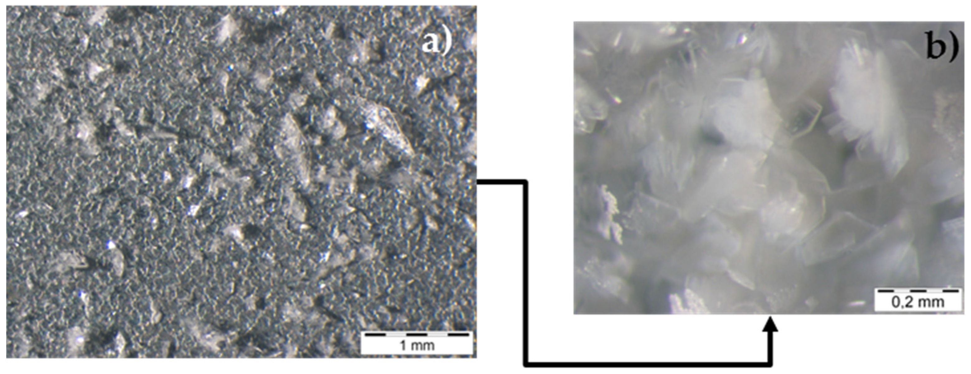
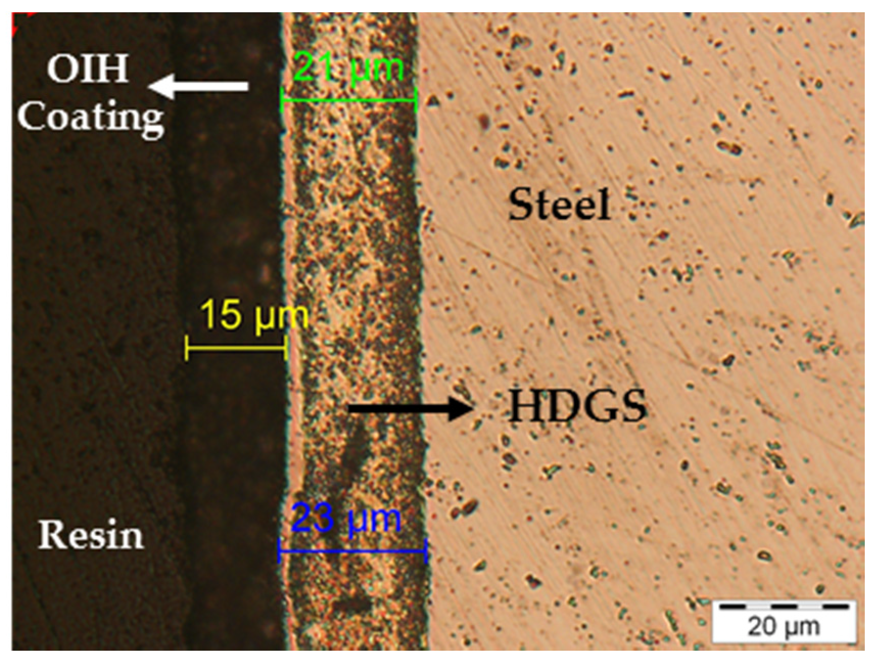
| Optical (light) Microscopy | Surface condition and microstructural features. Cross-section observation allows observation of the subsurface damage. Thickness measurements | Precise technique coating defects analysis and thickness measurements (quantitative analysis) | Highly skilled and trained technicians, destructive aspect of specimen preparation and sampling. A considerable number of test specimens is required |
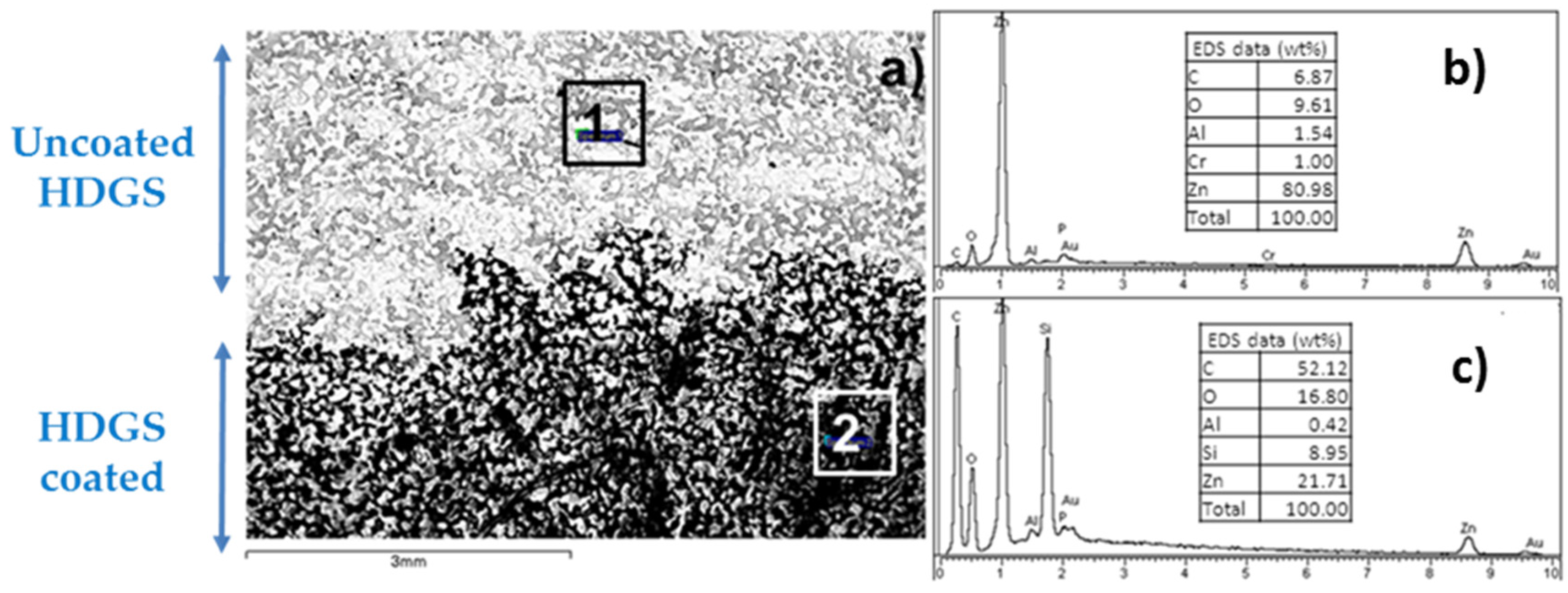
| SEM | Microstructural features and relationship between damage and structure, distribution of porosity, cracks and voids | High resolution (under 100 nm). Minor specimen preparation. Elemental chemical analysis is possible if coupled to an EDS. | A highly skilled and trained technician, data interpretation is moderate to difficult and may require experience. Specialized equipment |
| EDS | Qualitative and quantitative analysis of chemical elements | Carried out together with SEM | Specialized equipment in conjunction with SEM. Near-surface analysis. Highly skilled and trained technicians. Elements analysed with Z > 5 or > 11. Sample dimension is limited |
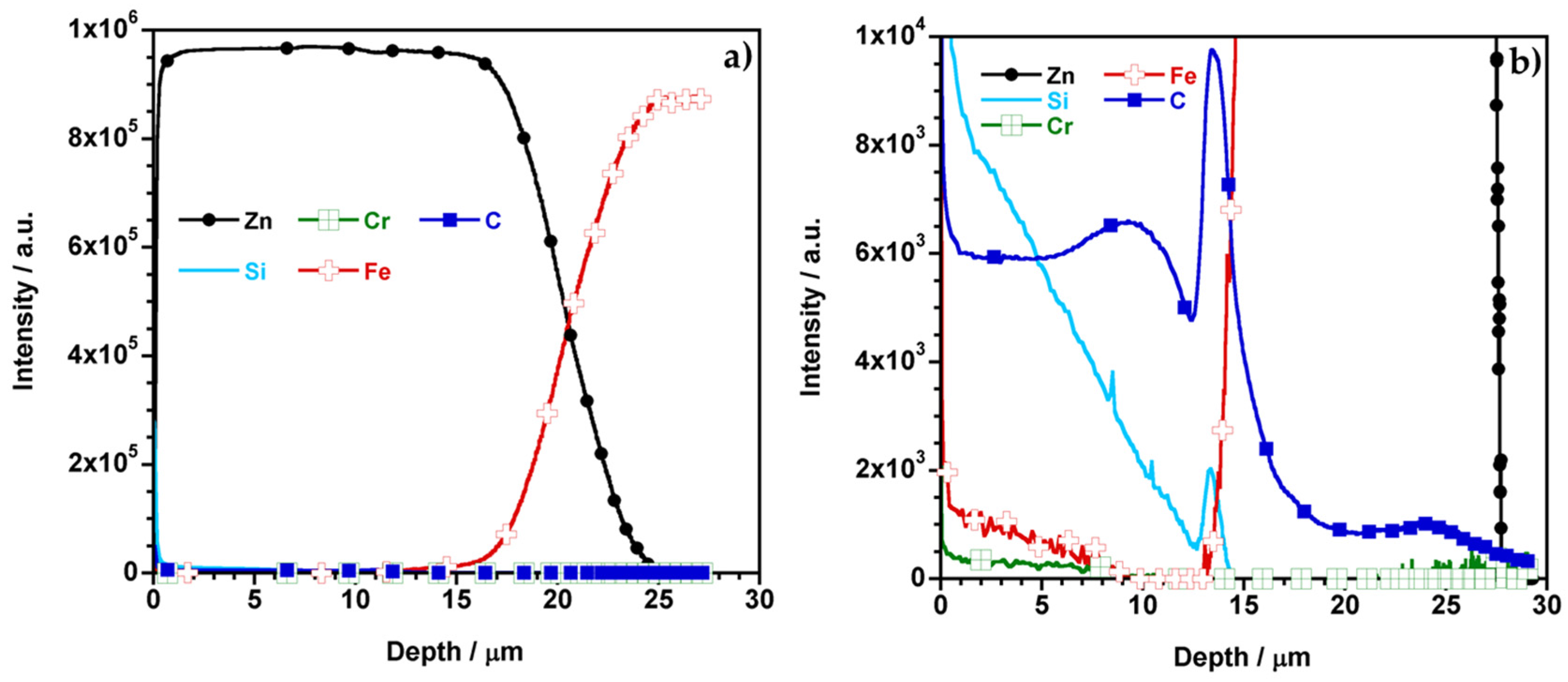
| GD-OES | Qualitative and quantitative analysis of all chemical elements | High sensibility (>10 ppm), rapid analysis, all elements can be detected | Sample dimension is limited |
| Raman spectroscopy | Molecular composition | Molecular information | Elements analysed with Z > 5 or > 11. Sample dimension is limited |
| Type of Deterioration | Basic Component | Bolted/Riveted Connector | Welded Connector | Coating System | ||||
| Uniform | Localized | Uniform | Localized | Uniform | Localized | Uniform | Localized | |
| NDM | Visual inspection, UM | Visual inspection, radio/gammagraphy, UM; Foucault Current | Visual inspection, UM | Visual inspection; UM; Foucault Current | Visual inspection, UM | Visual inspection; UM; Foucault Current | Visual inspection, UM; radio /gammagraphy (metallic coatings) | |
| DM | Tensile testing; Fracture testing; Hardness; Chemical analysis, Metallography, Electrochemical methods | Chemical analysis, Pull off; Metallography | ||||||
| Type of Discontinuity | Crack | Fracture | Crack | Fracture | Crack | Fracture | Flaking | Delamination |
| NDM | Visual inspection; UM; radio/gammagraphy; Foucault currents | Visual inspection, Foucault currents | ||||||
| DM | Tensile testing; Fracture testing; Hardness; Chemical analysis, Fatigue testing; Metallography and Fractography in case of fracture | Pull off; Metallography | ||||||
© 2017 by the authors. Licensee MDPI, Basel, Switzerland. This article is an open access article distributed under the terms and conditions of the Creative Commons Attribution (CC BY) license ( http://creativecommons.org/licenses/by/4.0/).
Share and Cite
Price, S.J.; Figueira, R.B. Corrosion Protection Systems and Fatigue Corrosion in Offshore Wind Structures: Current Status and Future Perspectives. Coatings 2017, 7, 25. https://doi.org/10.3390/coatings7020025
Price SJ, Figueira RB. Corrosion Protection Systems and Fatigue Corrosion in Offshore Wind Structures: Current Status and Future Perspectives. Coatings. 2017; 7(2):25. https://doi.org/10.3390/coatings7020025
Chicago/Turabian StylePrice, Seth J., and Rita B. Figueira. 2017. "Corrosion Protection Systems and Fatigue Corrosion in Offshore Wind Structures: Current Status and Future Perspectives" Coatings 7, no. 2: 25. https://doi.org/10.3390/coatings7020025