1. Introduction
The concept of high-entropy alloys (HEAs) is a new alloy design philosophy that was proposed recently, breaking the bottleneck stage of the conventional alloy design concept. The HEA philosophy considers that multiple principle elements in an alloy system will not produce brittle phases such as intermetallic compounds (IMCs) or other complex phases, leading to brittleness and difficulties in processing and application. On the contrary, the high entropy effect can maintain the simple solid solutions in alloys [
1,
2,
3]. The main reason people think multiple principle elements will decrease the property of the alloy is the Gibbs phase rule. According to the Gibbs phase rule,
f =
n −
p + 1 (
f, freedom degree;
n, component number;
p, phase number), the equilibrium solidification phase number for
n kinds of elements is given by
p =
n + 1. Since phase formation processes are always non-equilibrium solidification, the number of phases tends to be given by
p >
n + 1. More precisely, as more types of principle elements are added to the alloy system, more complicated phases appear in it, which is harmful [
4]. However, a new path of alloy design was carried out for the first time by Yeh et al. [
5,
6] in 2004. They found that there were no IMCs if more than five types of principle elements were added into the alloy system and simple solid solutions could be gained. More and more scholars have now joined in the study of HEAs. HEAs are better than traditional alloys in many aspects because of their high entropy effect especially in the preparation of wear and corrosion-resistant coatings, which are reported to be good candidates as structural and functional materials. Much research has been done on the properties of different HEAs. Duan et al. [
7] found that the hardness of AlCoCrFeNiCu via arc melting was 475.3 HV, showing excellent tribological properties. Tian et al. [
8] collected nearly 100 kinds of HEA experimental results and found that hardness steadily increased with different atomic sizes. Among the previous HEAs studied, HEAs are usually synthesized via arc melting technology or casting methods, which can result in high costs due to the amounts of expensive alloying elements that are added. As wear and corrosion resistance is a surface phenomenon and mainly determined by the surface properties of a material rather than by the bulk properties, laser cladding is widely adopted in the coating preparation since it has many advantages such as energy concentration, a low substrate dilution rate, and a fast cooling rate. Chen et al. [
9] found that, with the increase in aluminum content, Al
xCoFeNiCu
1−x HEAs displayed a greater hardness. An et al. [
10] prepared MoFeCrTiWAl
xSi
y coatings via laser cladding, which can obtain excellent quality coatings with the simultaneous addition of Si and Al.
Many HEA compositions are possible, and one well-known system is Al–Fe–Cr–Co–Ni. The evolution of the phase/microstructure was attributed to rapid quenching during laser processing. Alloy systems possess attractive properties such as high hardness, abrasiveness, and corrosion resistance. The addition of elements has a significant effect on the properties of HEA coatings [
11,
12]. It has been reported that Cu, Ni can promote the formation of a face-centered cubic (FCC) system, while Cr, Ti can lead to the formation of a body-centered cubic (BCC) system. The in-depth investigation on the effect of element addition on properties and structures may accelerate the application of HEA coatings. Thus, in this work, the effect of Ti addition on the properties and phase evolution of FeCoCrNiAlTi
x coatings is investigated, and the results of the present study on the rules of phase evolution, microhardness, and wear resistance would provide theoretical guidance to further explore the effects on the HEAs of other element additions.
2. Experimental Procedure
In this experiment, Q235 steel (SD Steel, Jinan, China) was chosen as the substrate and the nominal chemical composition in wt % is 0.12%–0.2% C; 0.28% Cr; 0.2% Ni; 0.3% Si; 0.3%–0.67% Mn; 0.035% S; 0.04% P and Fe balance. The equiatomic ratio of the pure Co, Ni, Cr, and Al powder mixed with various concentrations of Ti powder (99.6%, 300 mesh, Tianjiu Ltd., Changsha, China) was chosen as the cladding powder. Fe powder was not included in the cladding powder since the Fe atoms can be introduced from the substrate due to the dilution, and the content can be regulated by controlling the power of laser. The mixed powder was ground via planetary ball mill for 10 h with a rotate speed of 200 r/min. The ground powder was preplaced on the surface of 100 mm × 100 mm × 10 mm cleaned Q235 substrates with a thickness of 1.5 mm. The laser generator (FL-Dlight-1500, Yuchen Ltd., Nanjing, China) was used to prepare the sample with a power of 800 W, a scanning speed of 3 mm/s, a spot size of 3 mm × 1 mm, an overlap rate of 30% with Ar protection (10 L/min), under which good quality FeCoCrNiAlTix (x = 0, 0.25, 0.5, 0.75, and 1 in at.%, respectively) HEA coatings of moderate dilution could be achieved. The cladded samples were cut into small cross sections for metallography. The samples were ground using a grinding machine; grinding started at 100, and then proceeded at 200 and then 2000 abrasive papers, which was followed by polishing using a 1 m diamond slurry. They were then etched by a 5% nitric acid alcohol solution. The scanning electronic microscope (SEM, S3400, Hitachi, Tokyo, Japan) equipped with an energy dispersive spectrometer (EDS, Hitachi) was used to observe the microstructure of coatings and determine the content of elements, while the X-ray diffraction (XRD, Shimadzu 7000, Kyoto, Japan) was used to identify the constituent phase with Cu Kα (λ = 0.154 nm) radiation at a step of 0.02°. The microhardness was tested by a Vickers hardness tester (HVS-5, Lai Hua Ltd., Laizhou, China) with a load of 200 g and a duration time of 10 s. Sliding wear tests of the samples were performed on the universal tester by the ball-on-plate configuration under a dry condition, and the WC ball was chosen as the contact head. The friction and wear tests were carried out with a frequency of 5 Hz for 20 min.
3. Results and Discussion
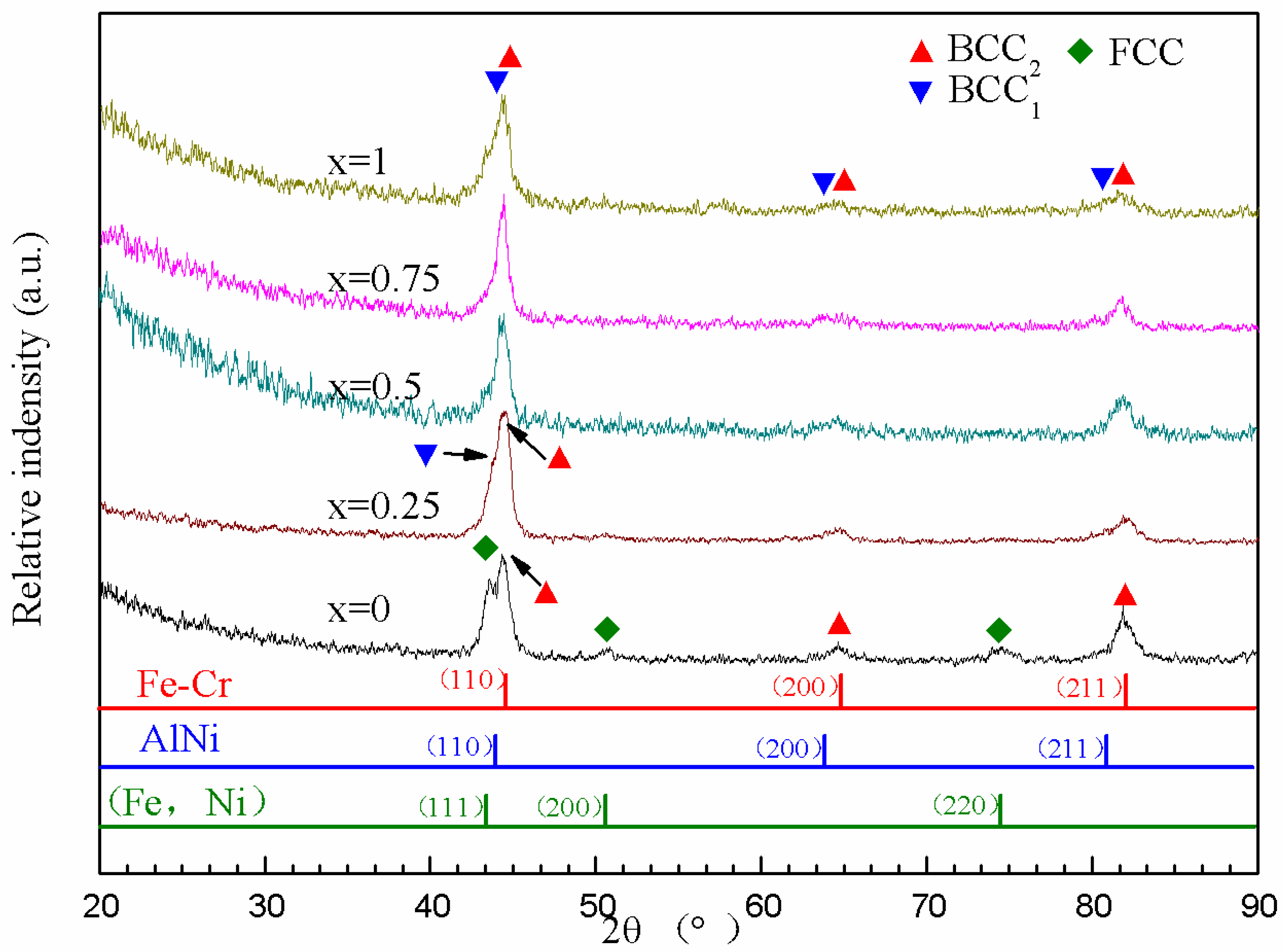
Figure 1 shows the XRD results of FeCoCrNiAlTi
x HEA coatings. It is obvious that both FCC and BCC
1 systems exist in the FeCoCrNiAl coating, which can be identified as (Fe, Ni) and Fe–Cr phases, respectively. However, the FCC system disappears in the FeCoCrNiAlTi
0.25 HEA coating and the AlNi, which is BCC forms. Ti is a BCC stabilizing element that restrains the formation of FCC. The AlNi is identified as BCC
2. Jiao et al. [
13] gained a similar result in the experiment where AlCoCrFeNiTi
x was deposited via arc melting and injection into a water-cooled copper mold.
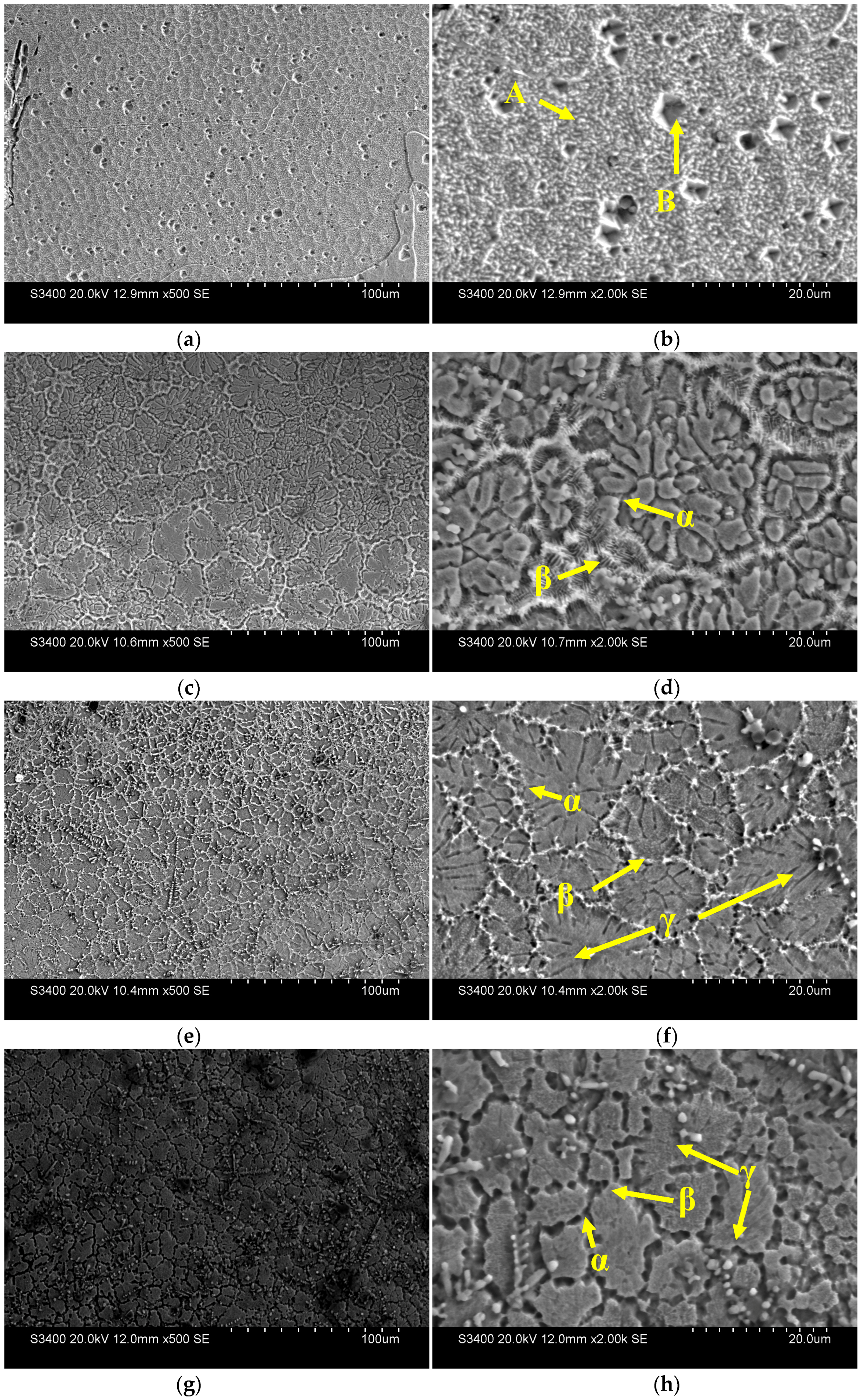
Figure 2 shows the cross-sectional SEM images of FeCoCrNiAlTi
x HEA coatings. There are two different phases in the microstructure at
x = 0. The chemical composition in different regions, as marked in
Figure 2, is listed in
Table 1. It can be seen by analyzing the EDS results in
Table 1 that the components of Zone A and Zone B is very similar. Thus, Zone B is a simple hole. There are only eutectic FCC and BCC
1 structures here. The structure morphology changes significantly with the addition of Ti. At
x = 0.25, the structure consists of the proeutectic phase α and the eutectic phase β. The proeutectic phase α exhibits an achrysanthemum-shaped microstructure, while the eutectic phase β is a typical lamellar. According to the EDS results shown in
Table 1, it can be concluded that the content of Ni and Al is high in phase α and the content of Fe and Cr is high in phase β. Combined with the former XRD results, it is obvious that the phase α is BCC
1, while the phase β is the eutectic phase of BCC
1 and BCC
2, respectively. The segregation of Ni, Al, Fe, and Cr in different phases can be attributed to the mixing enthalpies of atomic pairs between these six elements, as it is known that the mixing enthalpies indicate a tendency to order or cluster. The mixing enthalpies represent atomic interactions between the solute elements and the base solvent. It is easy to occupy the cluster center for a solute because it shows a negative Δ
H tendency and shows that a weak Δ
H tends to take the glue site. Such a cluster-based formulism has been validated in many FCC and BCC alloys, which satisfies specific composition formulas in limited quantities [
14].
The mixing enthalpy of atomic pairs between these six elements is listed in
Table 2. As shown in
Table 2, the mixing enthalpy of Al–Ni is −22 kJ/mol, so they have a good miscibility. However, the mixing enthalpies of Fe–Al and Cr–Al are −11 kJ/mol and −10 kJ/mol, respectively, which is relatively high among all of the pairs between Al and other elements. Therefore, Fe, Cr, and Al cannot have a good miscibility. Thus, Ni, Al and Fe, Cr segregate in different phases. According to the EDS results, the phase β is a Ti-enriched phase, indicating that the solid solubility of Ti in phase β is higher than that in phase α. This result is in accordance with Shun et al. [
15]. With the addition of Ti, the content of eutectic phase β decreases during the increase of proeutectic phase α. Thus, the eutectic point of BCC
1 and BCC
2 is between
x = 0 and
x = 0.25. As Ti content increases to
x = 0.5, some fine precipitates are precipitated out and the main component is Ti. The precipitates can hinder the dislocation glide, thereby enhancing the hardness and the strength. At
x = 1, equiaxed and fine grained microstructure is obtained in the structure and the eutectic phase β almost disappears.
Although there are several principle elements, the phase composition of the HEAs is relatively simple. There are only a few kinds of solid solutions in the coatings. The phase number of FeCoCrNiAlTi
x HEA coatings in this paper is much less than that calculated by the Gibbs phase rule. This phenomenon can be attributed to the high entropy effect, which can restrain the formation of complex intermetallic compounds. Otto et al. [
17] and Yao et al. [
18] also found this phenomenon. According to the Gibbs free energy formula:
where Δ
Hmix is the mixing enthalpy, Δ
Smix is the mixing entropy, and
T is the absolute temperature. It can be seen that the Δ
Gmix will decrease if the ΔS
mix increases. The high Δ
Gmix is the driving force for the formation of intermetallic compounds. Thus, the high entropy effect can decrease the Δ
Gmix of the system and contribute to the formation of saturated or supersaturated solid solution, thereby enhancing the solution strength effect and the mechanical properties.
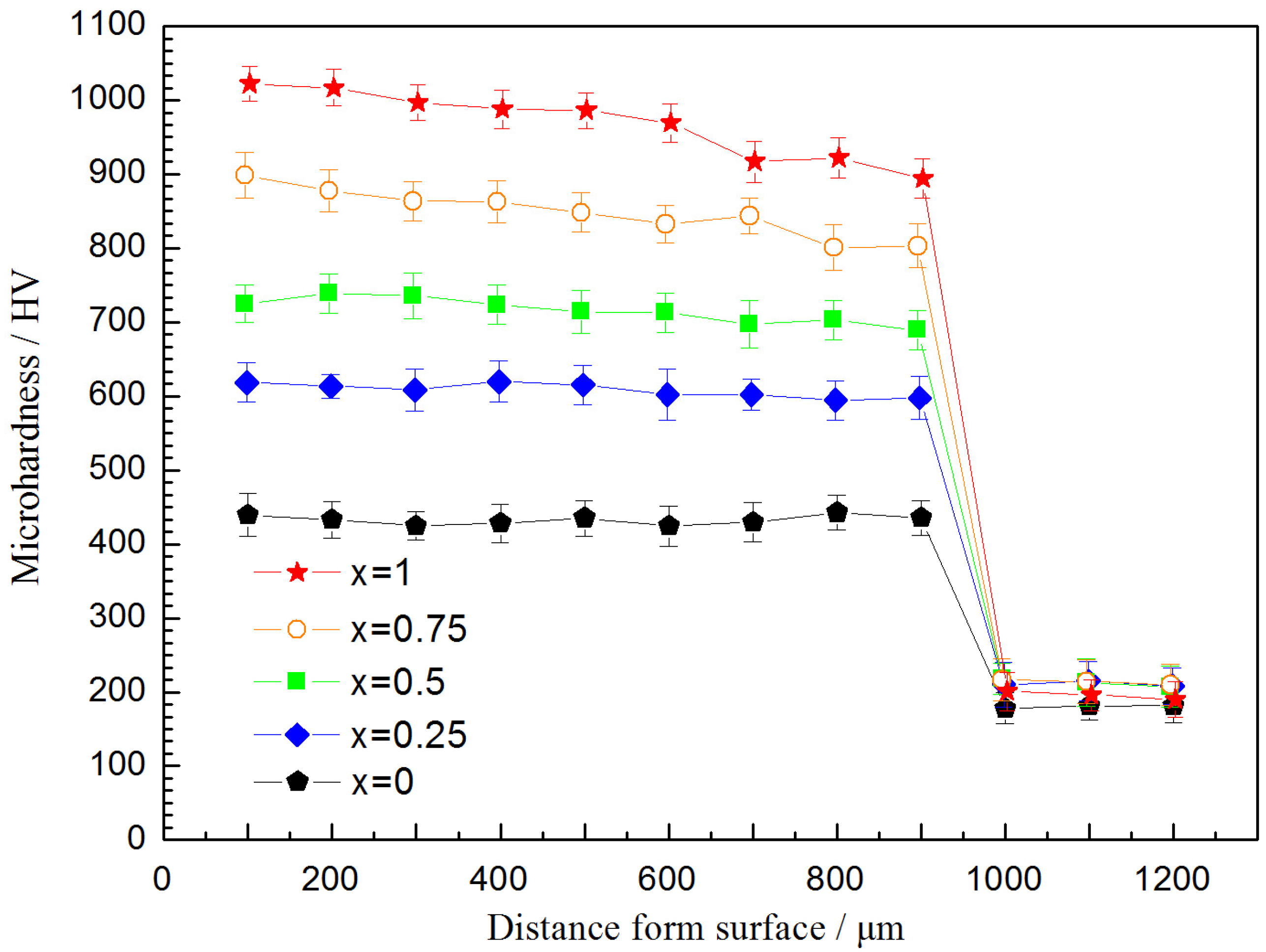
Figure 3 shows the results of the microhardness test along the cross section of the FeCoCrNiAlTi
x HEA coatings. The average microhardness of the HEA coatings at
x = 0, 0.25, 0.5, 0.75, and 1 are 432.73 HV, 548.81 HV, 651.03 HV, 769.20 HV, and 966.29 HV, respectively. It is obvious that the average hardness of FeCoCrNiAlTi
x HEA coatings increases as the content of Ti increases. The average hardness reaches its maximum point for the HEA at
x = 1, which is more than twice that of the HEA at
x = 0. The content of Ti in BCC
1 and BCC
2 persistently increases (as shown in
Figure 1) with the continuous addition of Ti. The atomic radii of Fe, Co, Ni, Cr, Al, and Ti are 124 pm, 125 pm, 121 pm, 124 pm, 143 pm, and 145 pm, respectively. It was easily observed that the radius of Ti is the highest among all elements. With the addition of Ti, the solid solute effect increases, leading to serious lattice distortion. Thus, the solid solution strengthening effect of Ti may be the most important reason, which contributes to the increase in hardness. In addition, the second phase strengthening effect caused by the separation of Ti is also an important reason. It can be seen in
Figure 3 that there is a softening region near the fusion line between the coating and the substrate. In this zone, the grains are coarse, which affect the mechanical properties of the coatings.
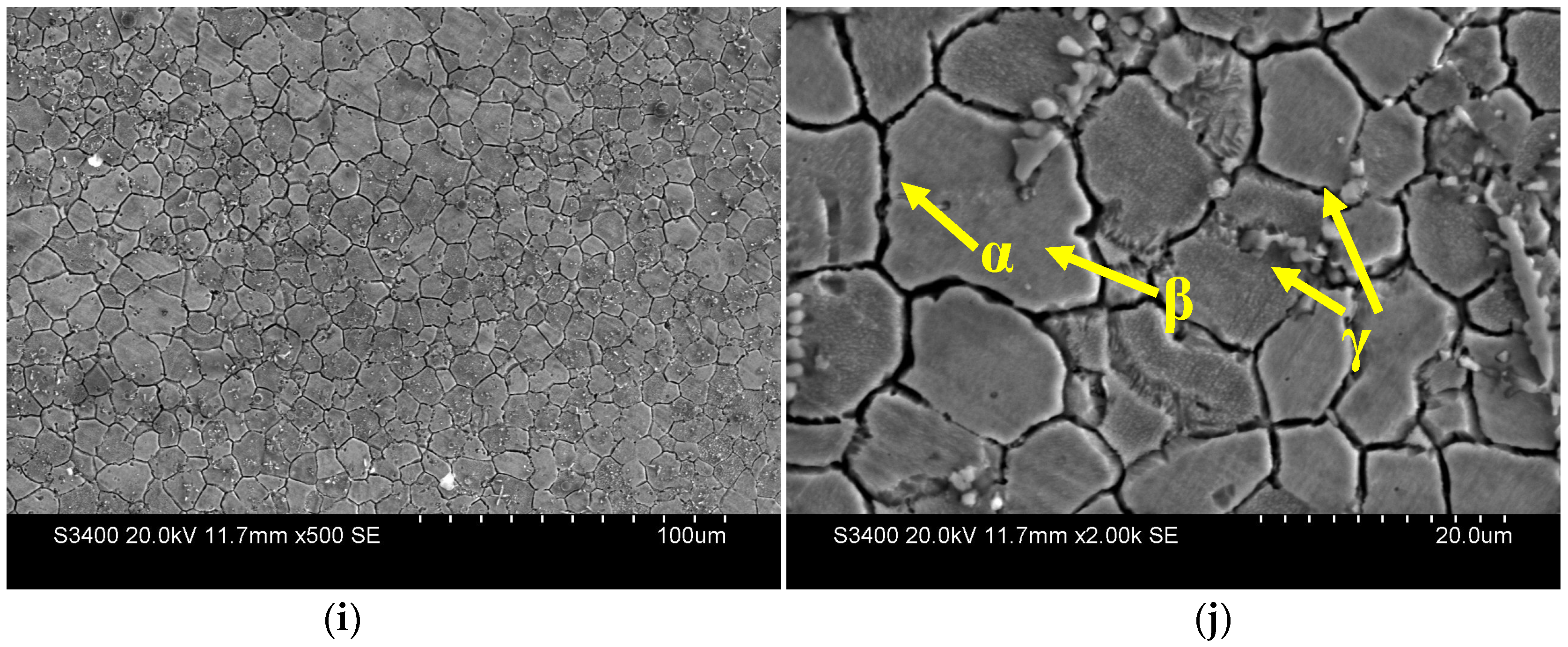
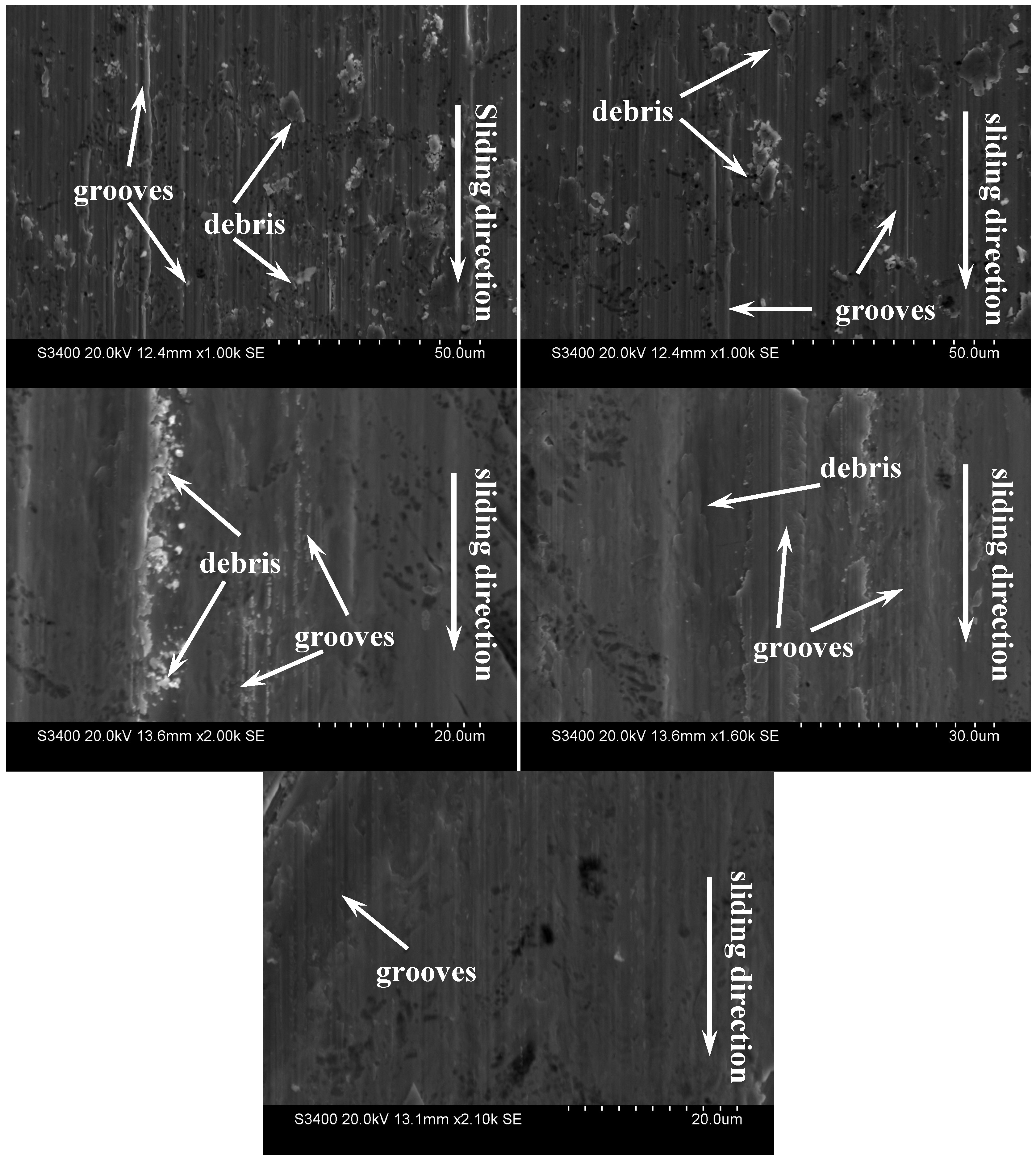
Figure 4 shows the worn surface morphologies of FeCoCrNiAlTi
x HEA coatings at the microscopic level. The surface tends to be smooth with the addition of Ti. Typically, the abrasion rate is connected with the resistance force at the contact surface during wear [
19]. A higher resistance force usually leads to a higher abrasion rate.
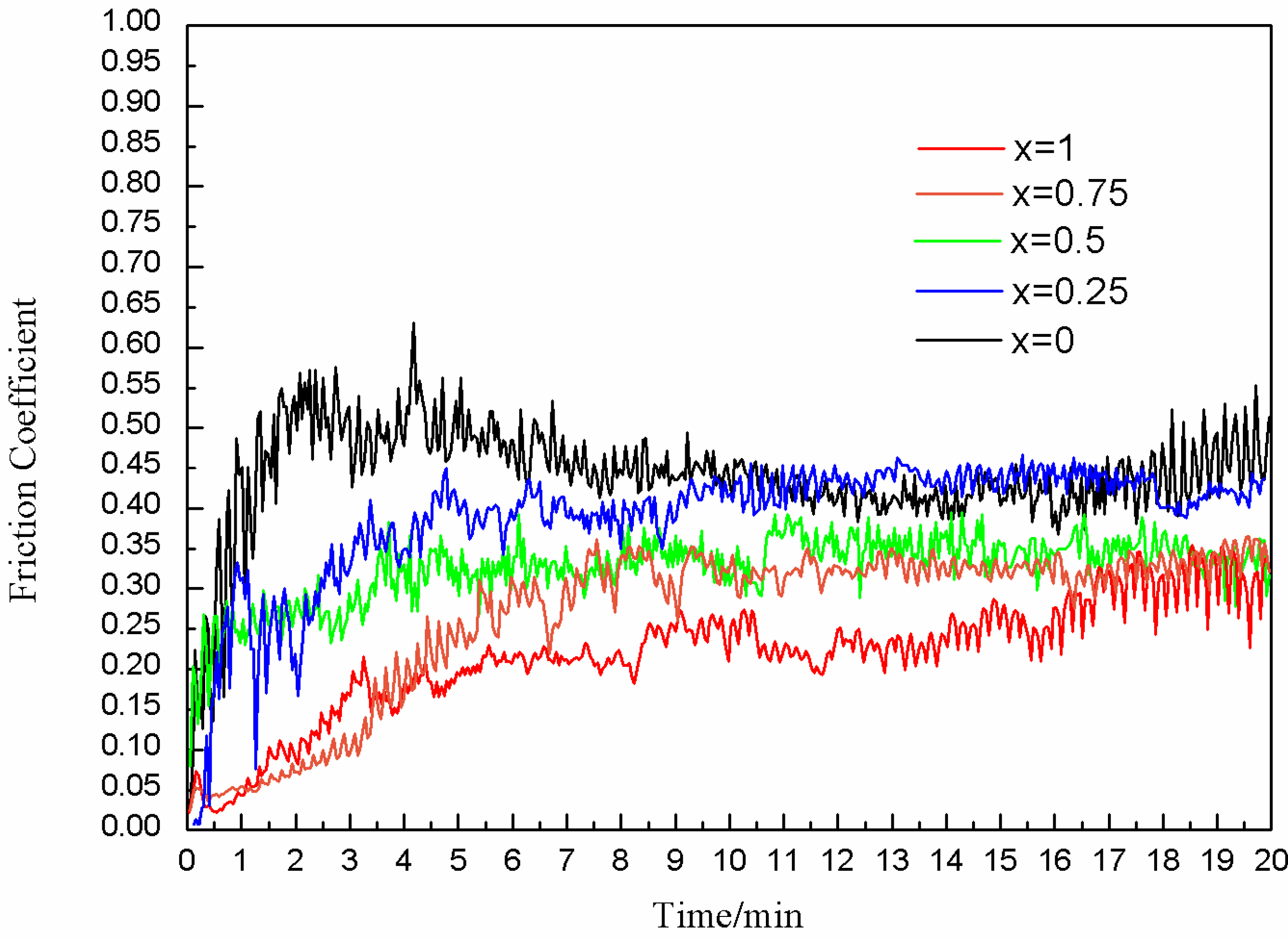
Figure 5 shows the variations in the friction coefficient curves of FeCoCrNiAlTi
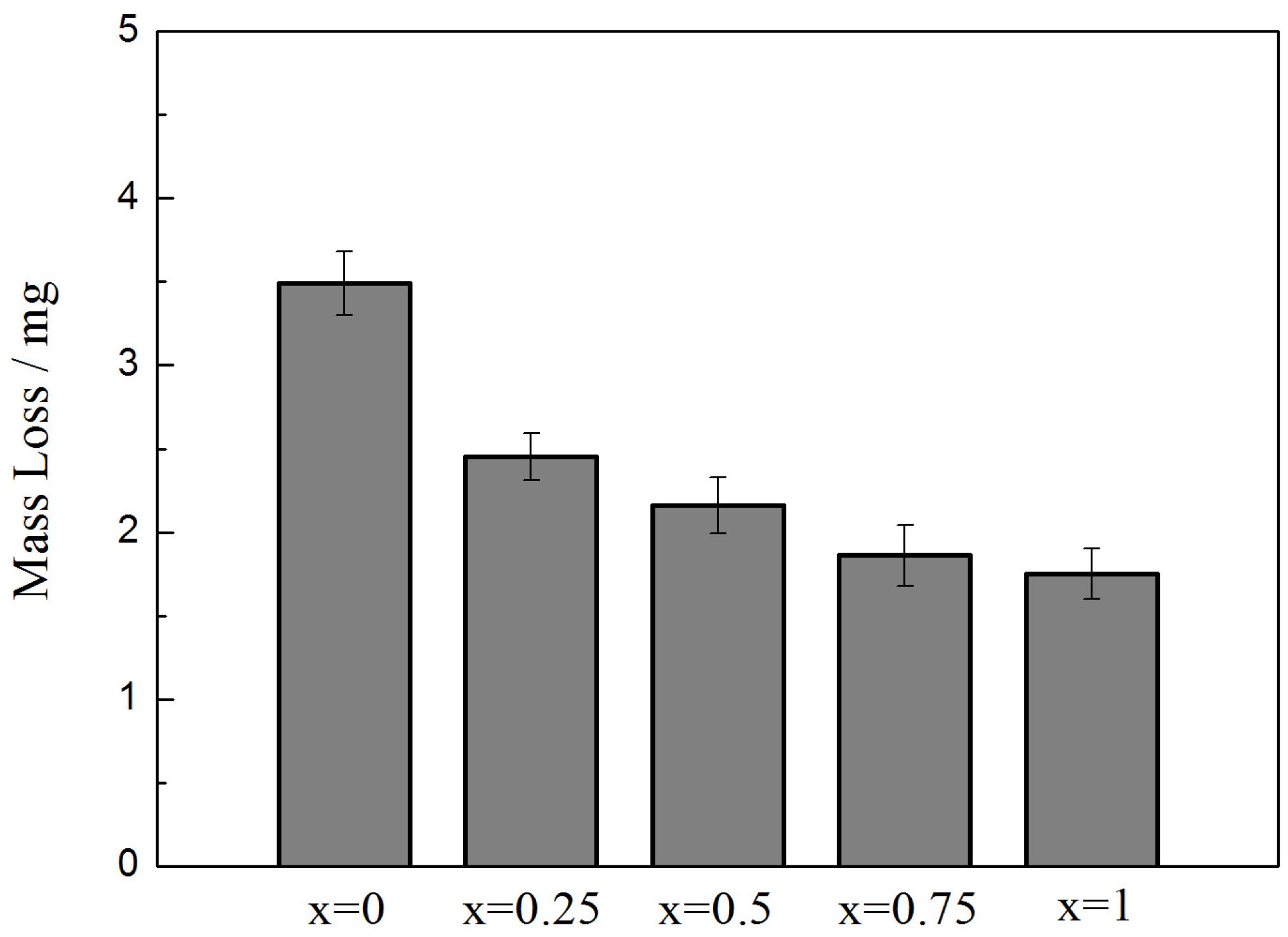
x coating as a function of wear test time. The mass loss is proportional to the friction coefficient in
Figure 6. According to the surface morphology, there are no obvious pits or other morphology features of adhesive wear. There are grooves and debris on the worn surface. Thus, the worn mechanism is the abrasive wear. At
x = 0, the grooves are deep, and there is substantial debris. The mass loss is also higher for the HEA at
x = 0, so the wear resistance is lower compared to the HEAs with higher Ti concentrations. At
x = 0.25, the amount of debris decreases, and the grooves are shallow. It is obvious that the wear resistance of the coating is enhanced with the addition of Ti. At
x = 0.5 and 0.75, the deep grooves disappear. At
x = 1, only a few shallow grooves can be seen, and there is no debris. The mass loss of FeCoCrNiAlTi
x coatings is the lowest at
x = 1, according to
Figure 6, indicating optimum wear resistance.


