Article

Influence of Isothermal Heat Treatment on Porosity and Crystallite Size in Axial Suspension Plasma Sprayed Thermal Barrier Coatings for Gas Turbine Applications

Department of Engineering Science, University West, Trollhättan 46186, Sweden
*
Author to whom correspondence should be addressed.
Coatings 2017, 7(1), 4; https://doi.org/10.3390/coatings7010004
Submission received: 15 November 2016 / Revised: 25 December 2016 / Accepted: 26 December 2016 / Published: 28 December 2016
(This article belongs to the Special Issue Thermal Spray Technology)

Abstract

:
Axial suspension plasma spraying (ASPS) is an advanced thermal spraying technique, which enables the creation of specific microstructures in thermal barrier coatings (TBCs) used for gas turbine applications. However, the widely varying dimensional scale of pores, ranging from a few nanometers to a few tenths of micrometers, makes it difficult to experimentally measure and analyze porosity in SPS coatings and correlate it with thermal conductivity or other functional characteristics of the TBCs. In this work, an image analysis technique carried out at two distinct magnifications, i.e., low (500×) and high (10,000×), was adopted to analyze the wide range of porosity. Isothermal heat treatment of five different coatings was performed at 1150 °C for 200 h under a controlled atmosphere. Significant microstructural changes, such as inter-columnar spacing widening or coalescence of pores (pore coarsening), closure or densification of pores (sintering) and crystallite size growth, were noticed in all the coatings. The noted changes in thermal conductivity of the coatings following isothermal heat treatment are attributable to sintering, crystallite size growth and pore coarsening.

1. Introduction

Hot section components, such as combustors, turbine blades, vanes, and afterburners in gas turbine engines, are protected by an insulating ceramic-metallic multilayer system known as a thermal barrier coating (TBC) [1,2]. A schematic of a typical as-sprayed TBC is shown in Figure 1, and comprises a metallic layer known as the bond coat followed by a ceramic layer known as top coat, deposited on a metallic substrate. Usage of TBCs for thermal protection of hot section components of aero-engines helps in increasing the overall engine efficiency by allowing higher combustion temperatures [1,2,3]. Apart from aero engines, TBCs are also deposited on industrial gas turbines (IGTs) and diesel engines for high temperature protection [4]. The most widely used top coat material is 8 wt.% yttria stabilized zirconia (8YSZ) [1,2], due to its superior properties such as high phase stability, low thermal conductivity, thermal expansion coefficient closer to that of the widely used Ni-base superalloy substrates and chemical inertness [5,6] compared to other ceramics.
Conventional deposition techniques for TBCs are atmospheric plasma spraying (APS) and electron beam physical vapor deposition (EB-PVD) [4]. APS is a cheaper technique and allows TBCs with a porous lamellar structure that yields lower thermal conductivity [7]. EB-PVD, on the other hand, is relatively expensive but allows coatings with an inherently strain tolerant columnar structure with relatively denser coatings than APS [8]. EB-PVD coatings, hence, typically have higher lifetime but also higher thermal conductivity than APS coatings for a given ceramic layer thickness [9,10,11,12].
Suspension plasma spraying (SPS) is a relatively more recent technique [13,14,15] that allows depositing porous as well as columnar structured TBCs, which can provide both strain tolerance and lower thermal conductivity and, hence, bear promise for providing enhanced lifetime as well as better thermal insulation [16,17,18,19,20]. SPS not only allows incorporation of higher porosity but also with widely varying pore size ranging from few nanometers to few micrometers [16,20,21]. Depositing TBCs with a columnar structure as in case of EB-PVD, but with higher porosity and in a more cost-effective manner, provides particular motivation for studying the SPS technique comprehensively.
Porosity is a key microstructural feature in a TBC which helps reduce the overall thermal conductivity of the coating, thus making it a better thermal insulator [17,22,23]. Hence, it is desirable to have a higher porosity in a TBC, while ensuring that it does not lead to premature degradation of the underlying bond coat through ingress of oxidizing/corrosive species. Notwithstanding the above, porosity measurement is a big challenge especially in SPS TBCs due to the presence of pores that span a wide dimensional scale, from nano-sized fine pores to large micron sized inter-columnar spaces [16,20,21]. Several techniques have been reported in literature to analyze porosity in TBCs [20,21], and the most commonly used are mercury infiltration porosimetry [20,24], image analysis [11,20] and water impregnation [17,25].
As mentioned earlier, TBCs are typically exposed to high temperatures (higher than 1000 °C) in gas turbines. At these temperatures, significant microstructural changes occur, which may affect the lifetime and functional performance of the TBCs [26,27]. Due to the presence of extremely fine as well as coarse pores in SPS sprayed YSZ layers [20], it is important to understand how these pores respond to sustain exposure to high temperatures and how the accompanying changes affect the thermal conductivity of the TBC. In view of its importance, the influence of high temperature exposure in terms of sintering of the ceramic-layer, pore closure etc. has been well-studied in case of both APS [28,29,30] and EB-PVD [31,32,33] TBCs. However such studies on SPS TBCs have been rare as per the author’s knowledge and, therefore, an attempt has been made to specifically address this issue in the present work.
Five different coatings, deposited with varying as-sprayed microstructures by employing different axial suspension plasma spraying (ASPS) spray parameters, were heat treated at 1150 °C in a controlled atmosphere (Argon) for 200 h to study the microstructural changes in the ceramic layer. The optimization of spray parameters using ASPS and understanding the role of various microstructures on thermal properties in as-sprayed condition was the subject of an already published previous work [16,20]. This work focuses on understanding the microstructural changes after the isothermal heat treatment and its influence on thermal properties. Pore coarsening (inter-columnar spacing widening or coalescence of pores), sintering (closure or densification of pores) and crystallite size growth were the three major microstructural changes specifically investigated in all the coatings.

2. Experimental Section

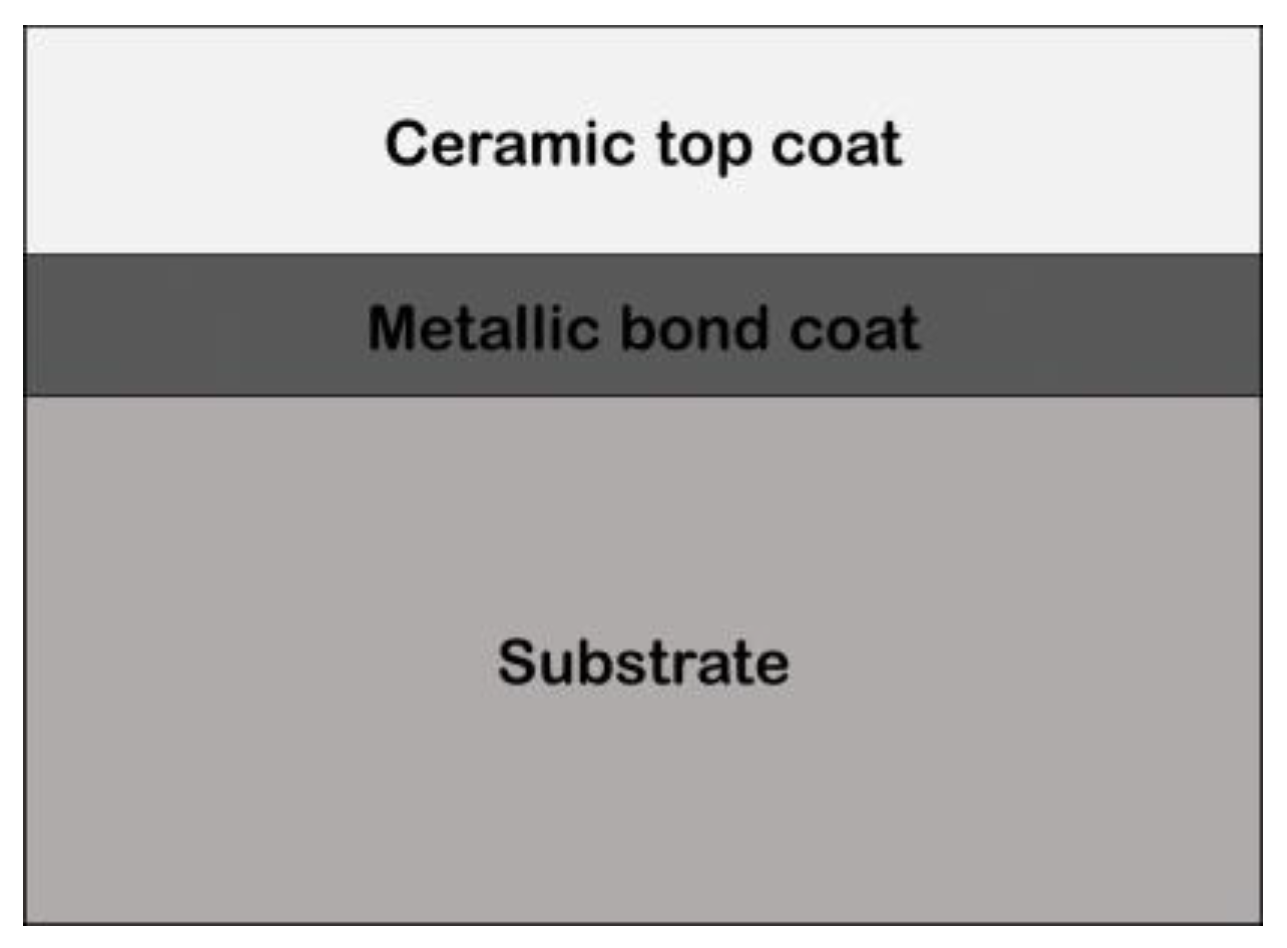
2.1. Coating Preparation

TBCs with five different 8YSZ ceramic top coat microstructures were deposited on Hastelloy® X (Haynes International, Ltd., Manchester, UK) substrates in the form of square plates (25 mm × 25 mm × 1.6 mm) and round buttons (ϕ 25 mm, 6 mm thick) by varying different spray parameters. Identical bond coats were deposited on all samples using a high velocity air-fuel (HVAF) equipment (Uniquecoat, Richmond, VA, USA). The powder used to deposit the bond coat layer (approx. 200 µm thick) was CoNiCrAlY (AMDRY 9951, Oerlikon Metco, Wholen, Switzerland). The top coat of 8YSZ was sprayed at atmospheric pressure using an Axial III high power plasma torch (Northwest Mettech Corp., Vancouver, BC, Canada) equipped with a Nanofeed 350 suspension feed system. The suspension used was 8YSZ (INNOVNANO, Coimbra, Portugal) with d50 = 492 nm and a solid loading of 25 wt.% powder in ethanol. Detailed experimental information regarding spraying of the above coatings can be found elsewhere [16]. However Table 1 shows clearly the 5 different coatings (Exp-1, 2, 3, 4 and 5) which are studied in this work were produced using different spraying parameters, hence show different microstructures which are discussed in detail in the recently published work [16].

2.2. Heat Treatment of the of Coatings Studied in this Work

All coating samples of size 25 mm × 25 mm × 1.6 mm were water jet cut into two ϕ 10 mm × 1.6 mm small coupons each. One of the two coupons from each type of coating was used to measure the thermal conductivity in as-sprayed state whereas the other coupon was subjected to heat treatment. All five different coupons to be treated were placed in a furnace at room temperature. The furnace was then evacuated, flushed with argon with a flow rate of (5 L/min) and heated to a temperature of 1150 °C in about 4 h. The samples were then held at this temperature for 200 h. Finally, all the samples were allowed to cool down to room temperature in about 4 h and removed from the furnace for post-treatment characterization.

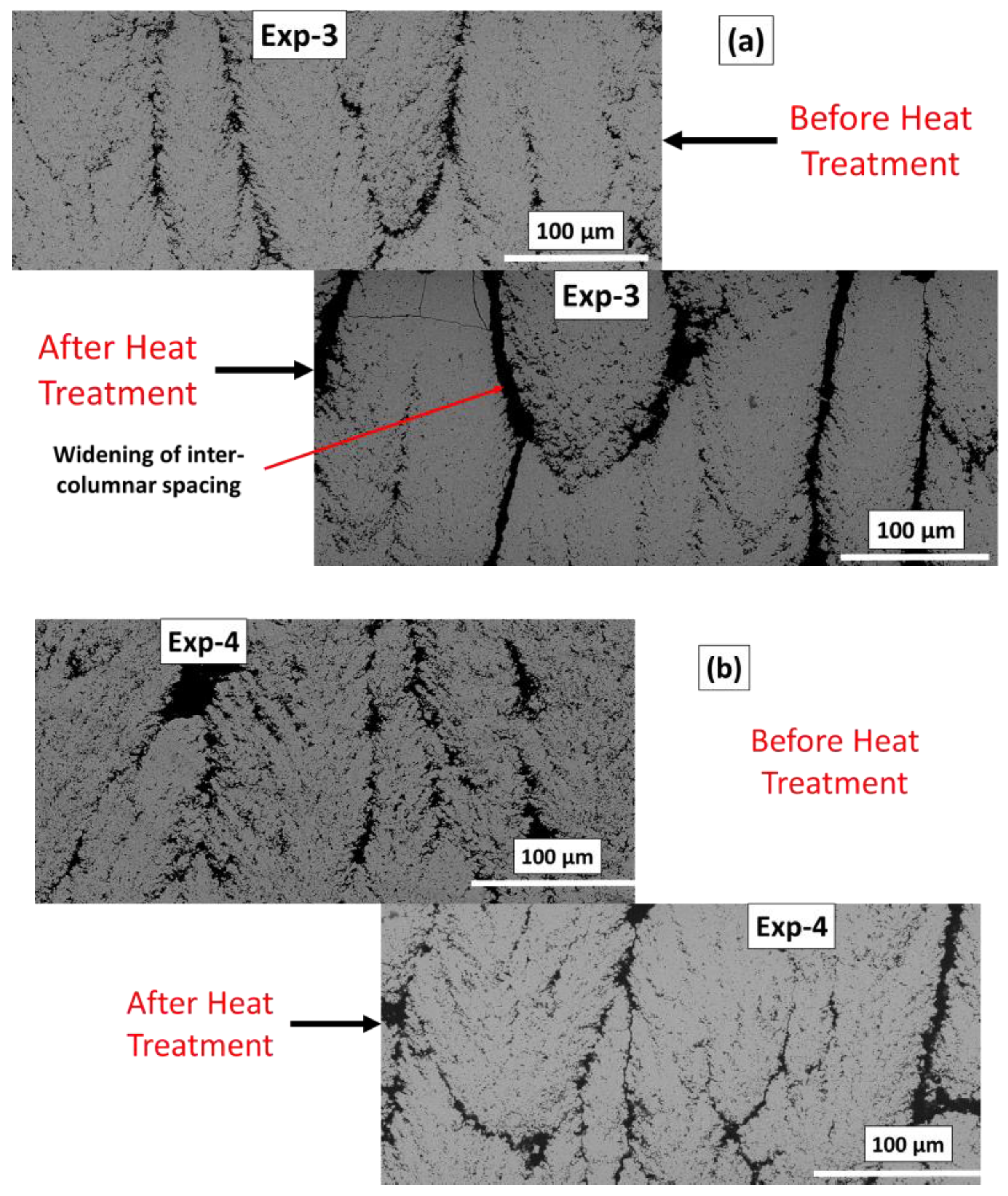
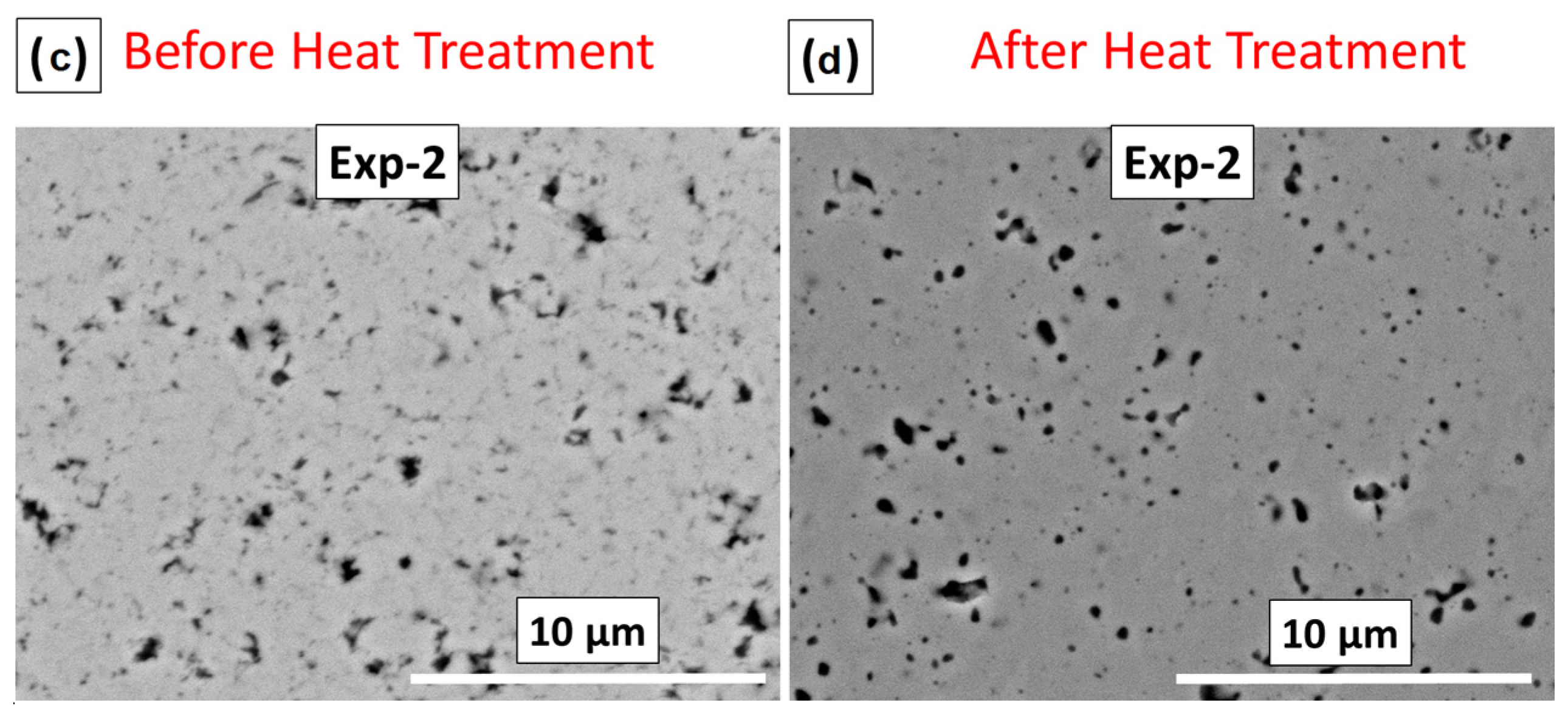
2.3. Microstructure Analysis

The TBC coated specimens (Top Coat + Bond Coat + Substrate) were first cold mounted in a low viscosity epoxy resin using vacuum impregnation and then cut using a diamond cutting blade. The transverse sections of the cut samples were again mounted in epoxy resin to enable microstructural examination on the coating cross-sections. All the samples were ground and polished using a semi-automatic Buehler PowerPro 5000 (Buehler, Lake Bluff, IL, USA), polishing machine. The microstructures were investigated with a scanning electron microscope (SEM) (HITACHI, TM3000, Tokyo, Japan). Further details regarding sample preparation can be found in work previously reported [16,20].

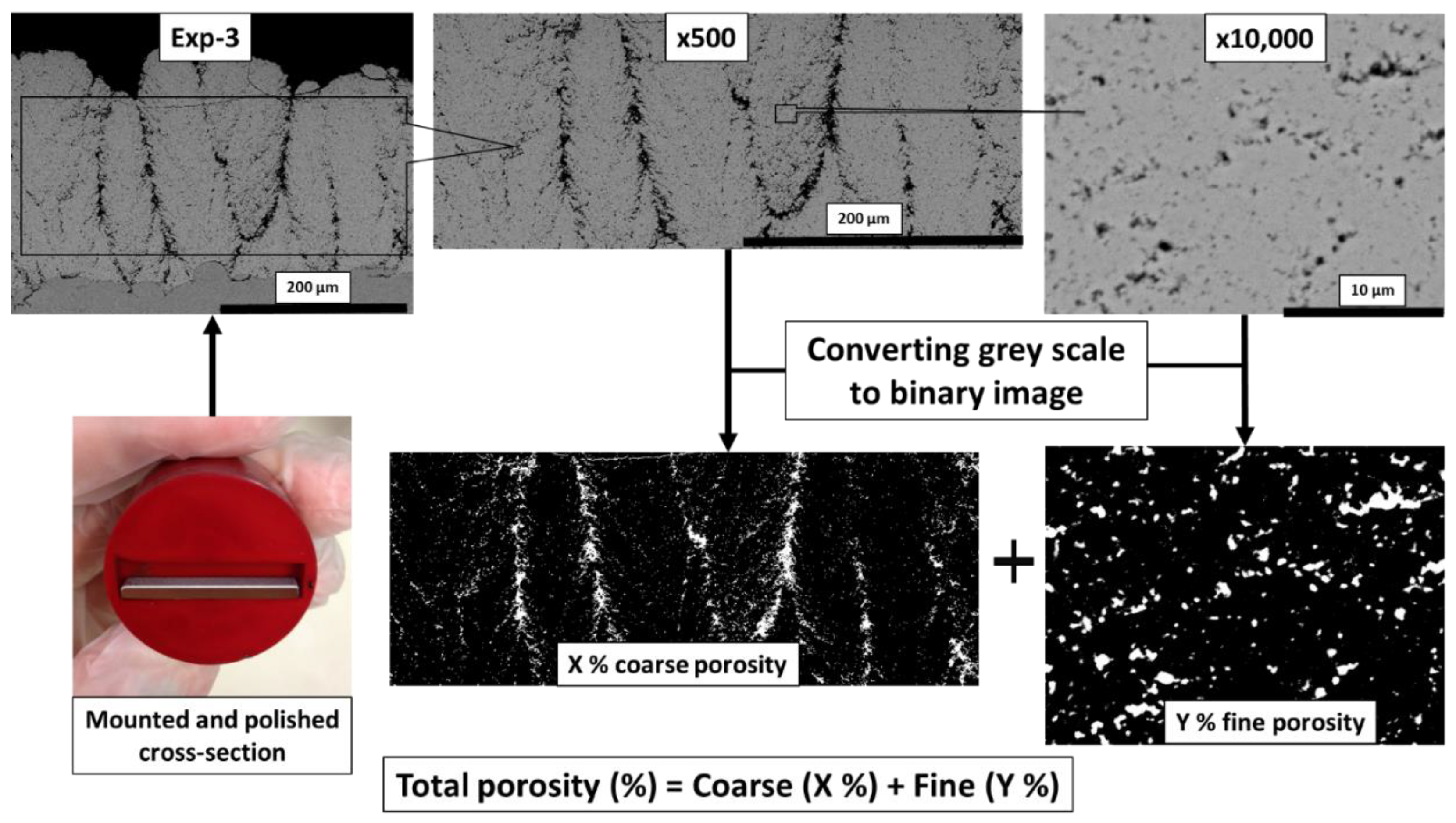
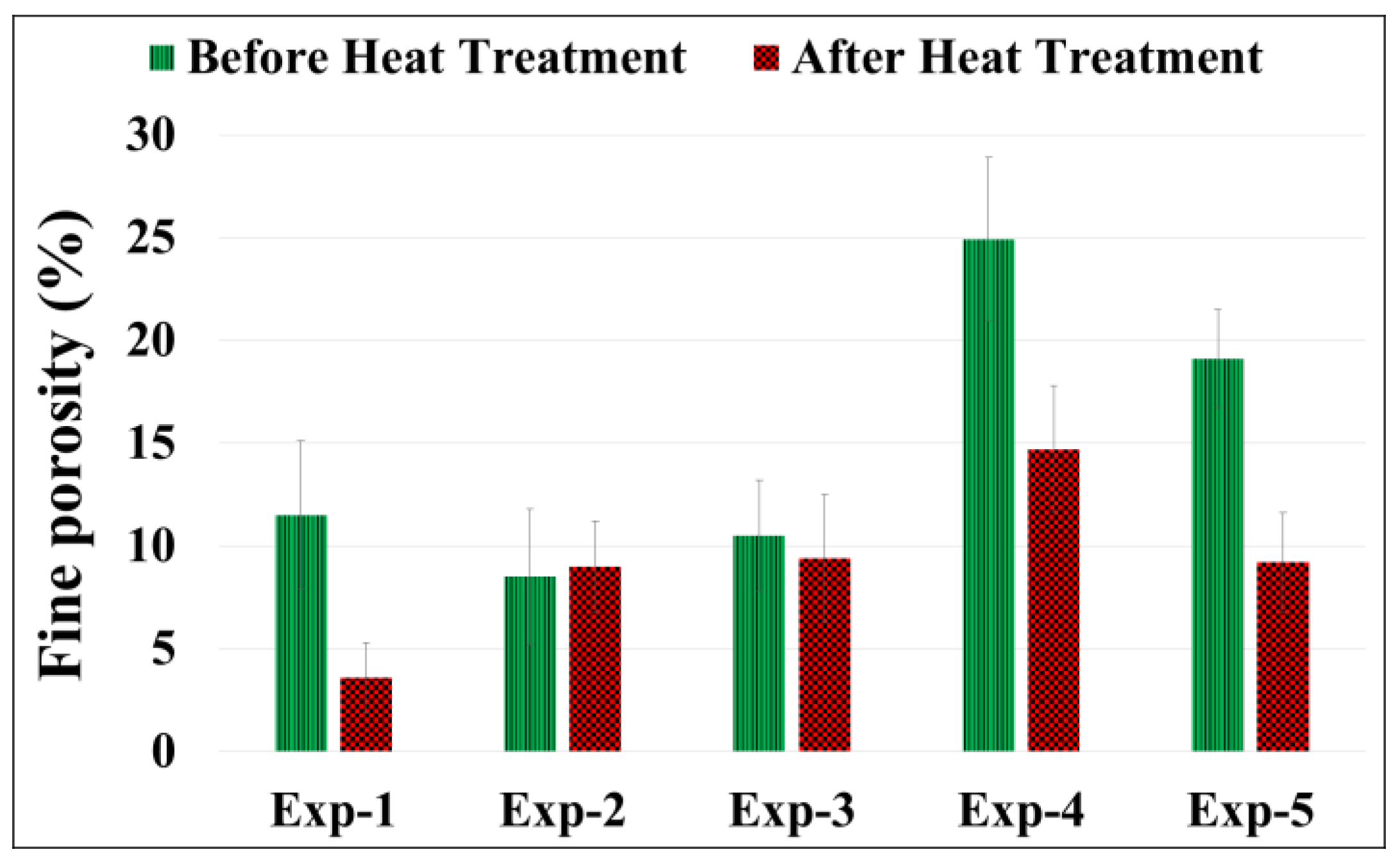
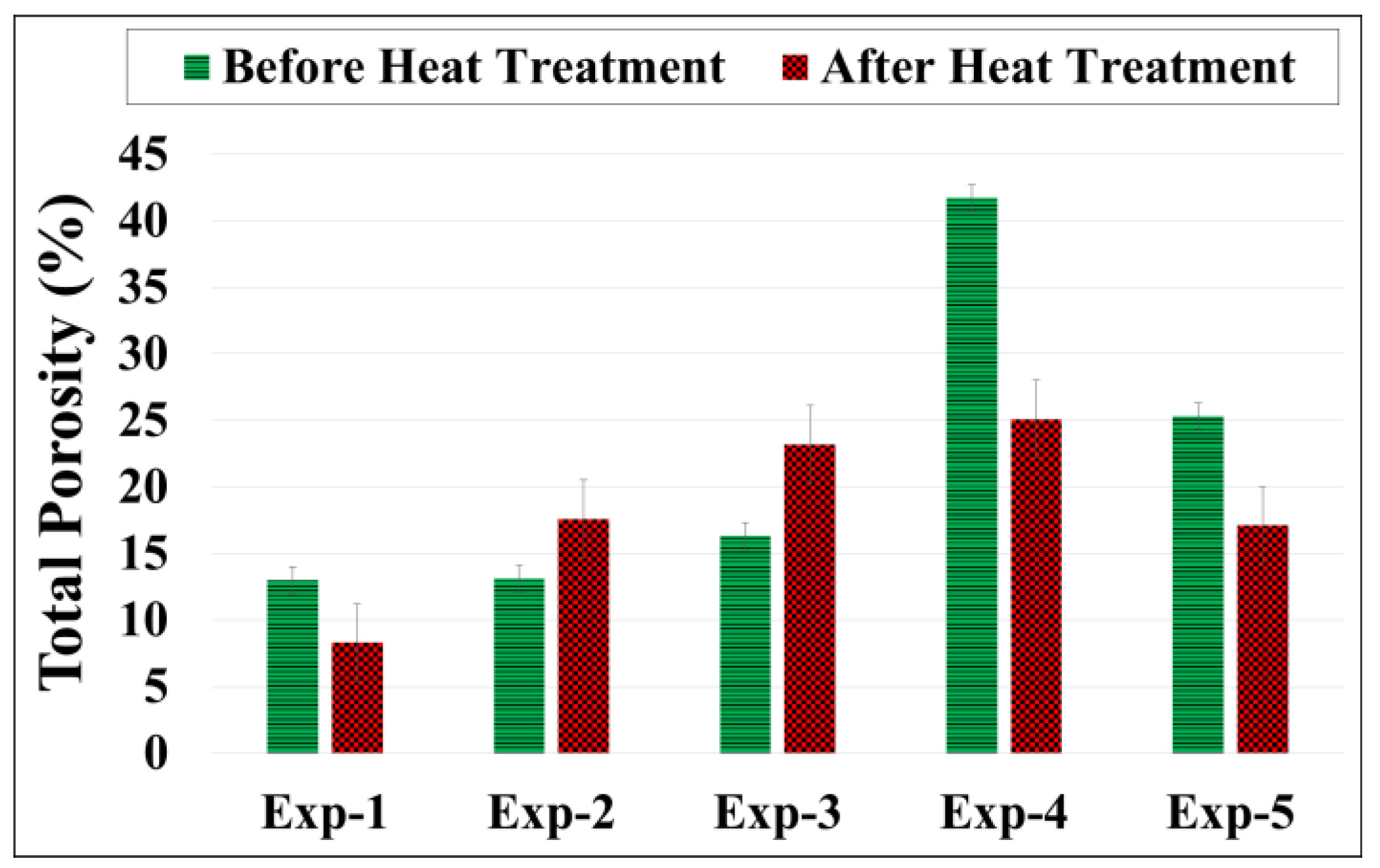
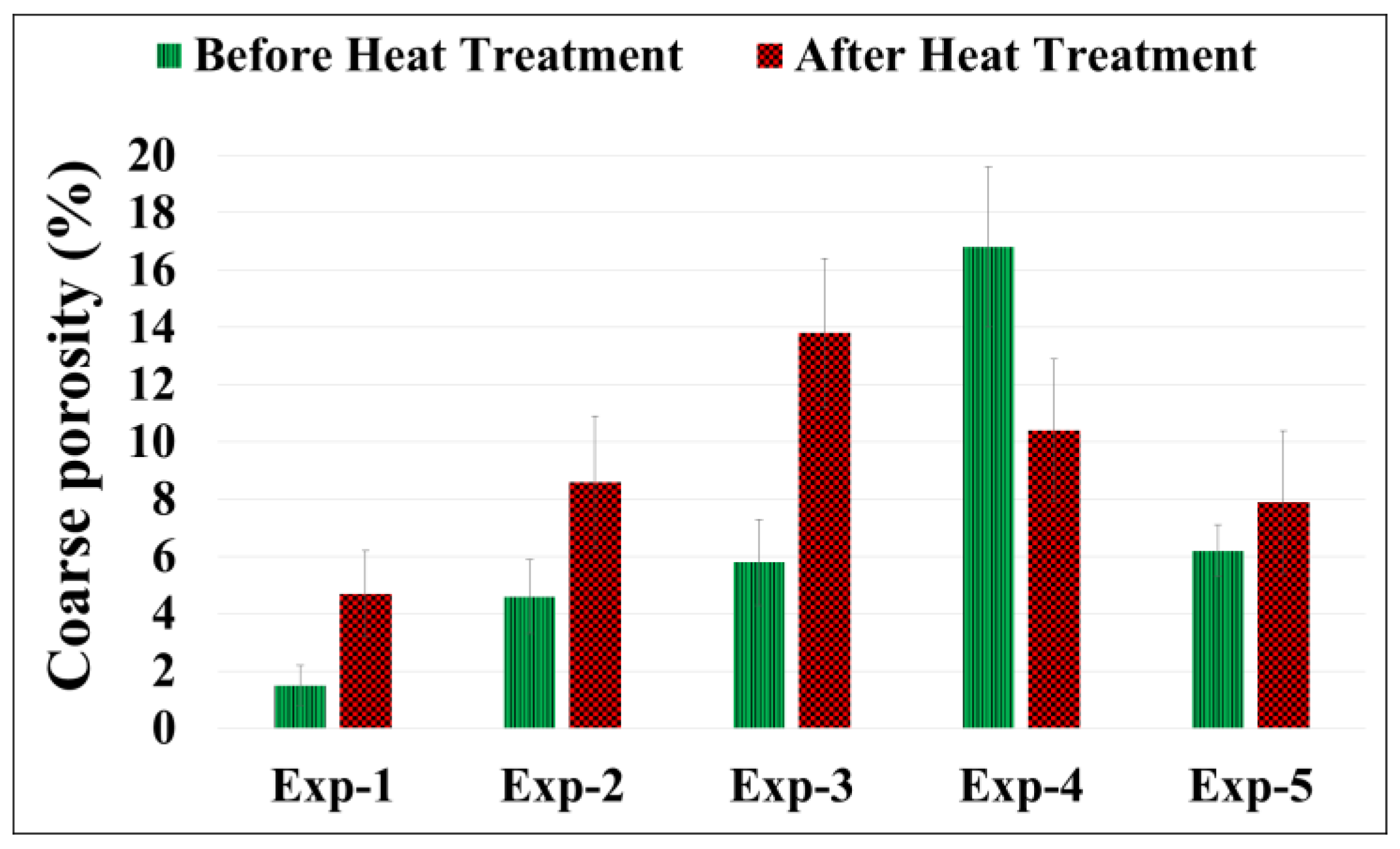
2.4. Porosity Measurement of Coatings

Image analysis technique was utilized in this work for porosity measurements and carried out using a commercially available Aphelion image analysis software (ADCIS, Paris, France). The image analysis routine of a conventional APS TBC microstructure images was initially developed in the HITS- Brite Euram project, in 2002 [34]. As mentioned earlier, the coatings studied in this work showed a large variation in pores’ size and, consequently, using a single magnification for examining all pores (as in the standard routine) was not possible. Therefore, two magnifications were utilized to analyze the SEM images with Aphelion, while keeping the rest of the image analysis routine the same.
The magnifications employed in this work were: (i) a low magnification (×500) to capture and analyze all the coarse pores with pore cross-section area bigger than 1 µm2 and (ii) a high magnification (×10, 000) to capture the fine pores with pore area smaller than 1 µm2.
The capture of images was done through the entire cross-section. Repetition from lower magnification was avoided while capturing the high magnification images. This was ensured by using a size threshold of 1 µm2 in both low (considering only >1 µm2) and high (considering only <1 µm2) magnifications to avoid repetition. As the SPS TBCs reveal a non-uniform distribution of pores through the coating, i.e., predominant large pores and spaces in the inter-columnar regions and small and fine porosity in the intra-columnar regions, the two magnifications targeted these two zones respectively. More specifically, the high magnification images were intentionally captured within the columns (away from the micron sized inter-columnar spacing/cracks) and low magnifications images were captured to include only the coarser features. Figure 2 shows the various measurement steps in the form of a flow diagram.
A total of 25 images were captured at both low and high magnifications. It is recommended to have more images at higher magnifications in order to have a better statistical estimation and 25 micrographs were deemed sufficient, as the two magnifications targeted specific zones in the coatings. Moreover, the purpose in this work was not so much to very accurately measure the absolute porosity but to perform a relative comparison between the different coatings, as well as between the as-sprayed and heat treated conditions. All the images were then converted into binary images (black and white). The porosity was then calculated by the software using the standard grey scale methods to distinguish between pores and the coating. The porosity determined from all the images was then averaged, first to separately determine the coarse and fine porosity at the respective magnifications and therefrom the total porosity by adding the coarse and fine porosity.
The image analysis technique adapted in this work, although tedious, can provide a reliable estimate of all types of porosity i.e., open (pores accessible by the fluid) or closed which are typically found in SPS TBCs [16,21] as well as the coarse and fine pores. This would be difficult by techniques such as water impregnation and mercury infiltration porosimetry which can measure only open porosity (pores accessible by the fluid) [16,20].

2.5. Phase Analysis and Crystallite Size Measurement

The phase constitution of as-sprayed and heat-treated coatings was identified by X-ray diffraction (XRD, Bruker AXS, Germany). XRD was performed using an X-ray Power D8 Discover diffractometer with Cu-Kα radiation in the 20°–90° 2θ range. Refined values of average crystallite sizes were obtained by exploiting the Rietveld method [35] and including a Lorentzian function for profile fitting. For the Rietveld refinement, CIF (Crystallography Information File) with the collection code 75309 in ICSD (Inorganic Crystal Structure Database) was used [36], i.e., phase with P42/nmcS space group. Rietveld refinement of the obtained diffraction pattern was done with TOPAS 4.2 software to (1) quantify the identified phases and the mean crystallite sizes and (2) refine lattice parameters.

2.6. Thermal Conductivity Measurement

Thermal conductivity is a measure of heat flow through a coating and the most widely adapted method to evaluate it for a TBC is to derive it from its thermal diffusivity. The relation between thermal conductivity (λ), thermal diffusivity (α), specific heat capacity (Cp) and the coating density (ρ) is shown below, where all symbols are in SI units:
λ =   α C p ρ
The coating density can be measured by any of the techniques that are appropriate for porosity measurement, but the image analysis technique described above was used in the present work. The measured mean total porosity as described in Section 2.4 was used to calculate the coating density using the following relation:
ρ   ( g cm 3 ) = ( 100 mean   total   porosity ) × 6.1   ( g cm 3 )
where 6.1 (g/cm3) is the density of the fully dense 8YSZ coating (without any porosity). Specific heat capacity was measured by differential scanning calorimetry in previously performed experiments [25,37] whereas for thermal diffusivity measurement the laser flash analysis (LFA) was employed using LFA 427 (Netzsch Gerätebau GmbH, Selb, Germany) equipment.
The diffusivity measurements were done on the multi-layer (top coat + bond coat + substrate) TBC systems as it is closest to the realistic conditions used on gas turbines. During the LFA experiment a laser beam of wavelength 1064 nm is fired at the substrate face of the 10 mm diameter round sample which raises the temperature of the TBC system. The increase in temperature at the top coat face is then measured with an IR detector. The signal is normalized and the diffusivity is then calculated using the relation as shown below [38]:
α = ( 0.1388 L 2 ) / t ( 0.5 )
where, α (m2/s) is thermal diffusivity, L (m) is the thickness of the top coat and t0.5 (s) is the time taken for the top face temperature of the ceramic TBC to reach one-half of its maximum rise. In this multilayer system the diffusivity values for substrate and bond coat were individually measured in the previous work [25,37]. These values were used to calculate the diffusivity of ceramic TBC by rule of mixture. More details about LFA measurement can be found in earlier works [16,17,20].

3. Results and Discussion

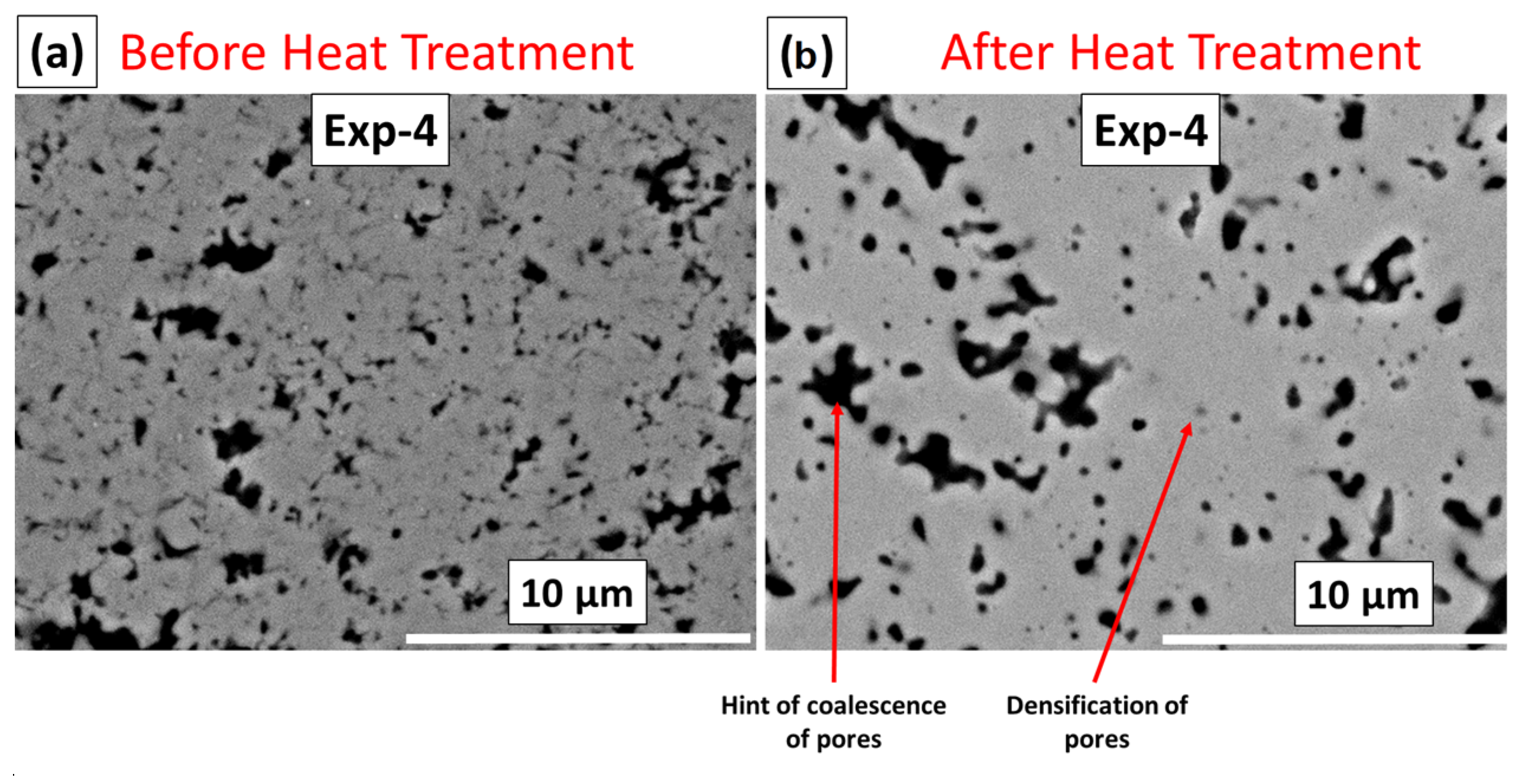
3.1. Microstructural Changes after Heat Treatment

A widely reported fact about plasma sprayed ceramic coatings is the closure of pores and cracks due to sintering upon prolonged exposure to high temperatures [28,39]. This can reduce the overall coating porosity compared to the as-sprayed coating [39]. However, the YSZ coatings studied in this work showed either an increase or a reduction in porosity, depending upon the as-sprayed microstructure of the coating prior to heat treatment. As it can be seen from Figure 3, the coatings Exp-1, Exp-4 and Exp-5 showed a significant decrease in porosity. On the other hand, coatings Exp-2 and Exp-3 showed an increase in porosity. Such increase in porosity after heat treatment is extremely unusual in case of conventional APS sprayed YSZ TBCs and rarely reported in the literature to the best of the authors’ knowledge. From the results (plotted in Figure 3), the increase in porosity in case of Exp-2 and Exp-3 can be seen clearly and such a finding has been reported in literature for SPS TBCs as well [15]. The above porosity increase has been attributed to pore coarsening in case of SPS TBCs. Exner et al. explained the pore coarsening effect in case of several powder compacts during solid state sintering by saying that the pore coarsening can be caused by localized transport of atoms/molecules due to diffusion and or bulk particle rearrangement [27]. Hence, apart from the anticipated microstructural change caused by sintering, the possibility of pore coarsening that might take place in certain conditions and be responsible for increase in the total porosity as noted in coatings Exp-2 and Exp-3, should also be borne in mind to explain the results observed. It should be noted that as defined earlier pore coarsening is both coalescence of pores and or widening of inter-columnar spacing.
In order to get a better insight into the influence of long term exposure to high temperature during heat treatment on the coating microstructure, it is educative to separately study the variations in coarse porosity (examined at 500×) and fine porosity (examined at 10000×). The so called “pore coarsening” effect was more specifically observed when only the coarse porosity captured at the lower magnification was considered which is depicted in Figure 4. It was noticed that all coatings, except Exp-4 (as shown in Figure 5b), revealed an increase in the coarse porosity after heat treatment. This can be primarily attributed to widening or opening up of the cracks or the inter-columnar spaces as clearly visible in Figure 5a in case of Exp-3. Such widening of inter-columnar spacing was also observed in literature for EBPVD coatings which was reported to be occurring due to the thermal expansion mismatch between the coating and the substrate (especially when higher thermal expansion coefficient for substrate than the coating was noticed) [33]. Exp-4 coating as introduced above did not show as significant change as Exp-3 or others in the inter-columnar spacing after heat treatment, which can be seen from Figure 5b. In fact, the figure shows a decrease in coarse porosity within the column. This could be the reason that the coating Exp-4 shows an overall decrease in the coarse porosity. It should be noted that, although the micrographs shown in Figure 5 before and after heat treatment are not exactly from the same location, the two metallographic samples were prepared from coupons cut from the same specimen with one of them being subjected to heat treatment. Thus, the above observation is representative and also further ensured by the fact that the data in Figure 4 is an overaged outcome of observations made on 25 separate images.
In contrast, the impact of heat treatment on the fine porosity is very interesting. Figure 6 shows the fine porosity content in coatings in as-sprayed condition and after heat treatment. It can be noted that the fine porosity either decreased (in case of Exp-1, Exp-4 and Exp-5) or remained virtually constant within the range of the error bars (in case Exp-2 and Exp-3). The overall decrease in fine porosity in some of the samples is suggestive of pores tending to get finer or close due to the sintering effect as has been reported previously in case of SPS, APS and EB-PVD TBCs [22,24,26,39,40]. On the other hand, the nearly constant fine porosity noted in some specimens even after heat treatment is indicative of superior sintering resistance.
The decrease in porosity following heat treatment is exemplified by the SEM micrograph in Figure 7a (for Exp-4). Although the decrease in overall porosity of Exp-4 before and after heat treatment is seen in Figure 7a, there is also a hint of some coarsening and or coalescence of the fine pores. Although the grown pores still appear to be within the threshold of the 1 µm2 pore area used to distinguish the ‘fine’ and ‘coarse’ pores as discussed in Section 2, a more detailed investigation involving determination of pore size distribution before and after thermal exposure can potentially provide further insights. Incidentally, such pore growth due to coalescence of individual pores has also been previously reported in case of EB-PVD TBCs [41,42]. Furthermore, it has been reported that sintering is not only pore size dependent but influenced by pore shape too [43]. Therefore, further investigation is also needed to understand the shape effect on the sintering resistance for SPS YSZ TBCs. Compared with all the other coatings, Exp-2 and Exp-3 did not show as significant change as other coatings and this was also observed from the SEM micrographs as shown in Figure 7b for coating Exp-2. Though, a hint of densification can be observed here as well as can be seen from the same figure.

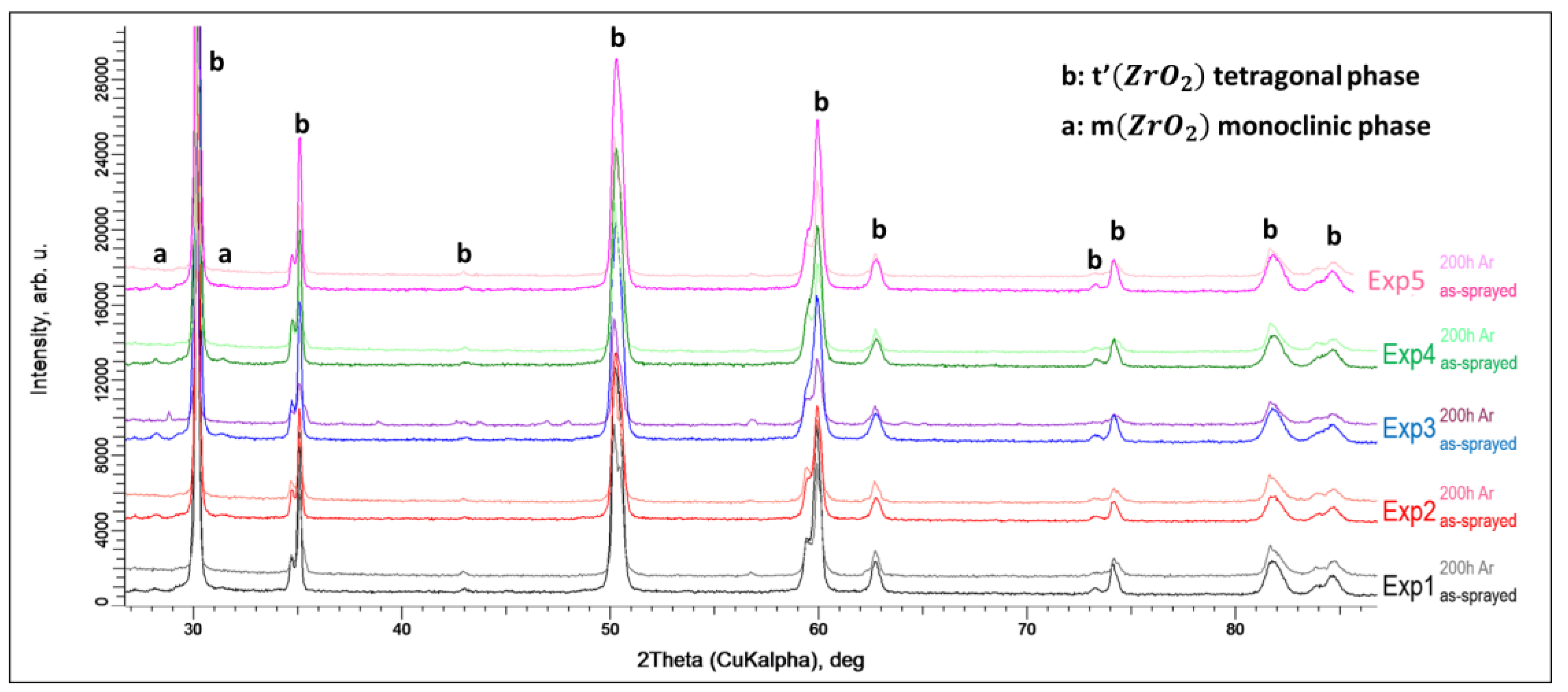
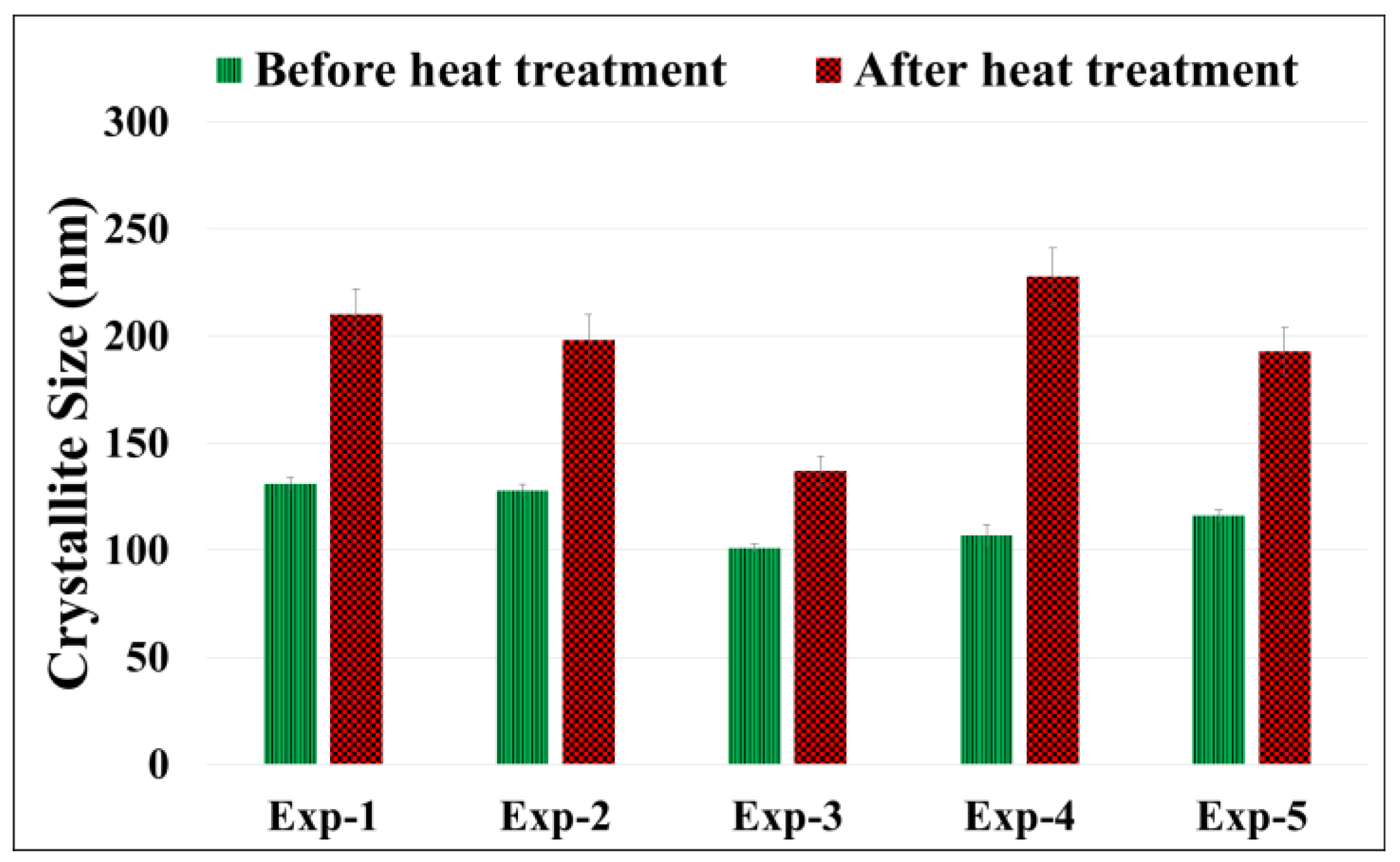
3.2. Phase Analysis and Crystallite Size Measurement Using XRD

The phase constitution of the top ceramic layer in the as-sprayed condition and after heat treatment was determined in case of all samples. The XRD patterns are depicted in Figure 8 and reveal that the major phase present in all coatings before heat treatment was the non-transformable tetragonal (t’) phase with a small amount of monoclinic phase also being noted. As expected, the crystalline phases present in all the coatings after heat treatment remained largely unchanged. As evident from the XRD patterns, after heat treatment there was no significant shift in the peaks for (t’), although some coatings exhibited a decrease in the monoclinic phase content. The non-transformable tetragonal (t’) phase is a metastable phase up to about 1200 °C and, hence, the heat treatment performed at 1150 °C did not result in any significant phase transformation.
Another change which was noticed, apart from pore coarsening and sintering previously discussed, was the variation in crystallite size upon thermal exposure. It can be seen from Figure 9 that all coatings undergo an increase in crystallite size during heat treatment. Such increase in crystallite size in YSZ TBCs has also been reported in literature in case of APS TBC [30].

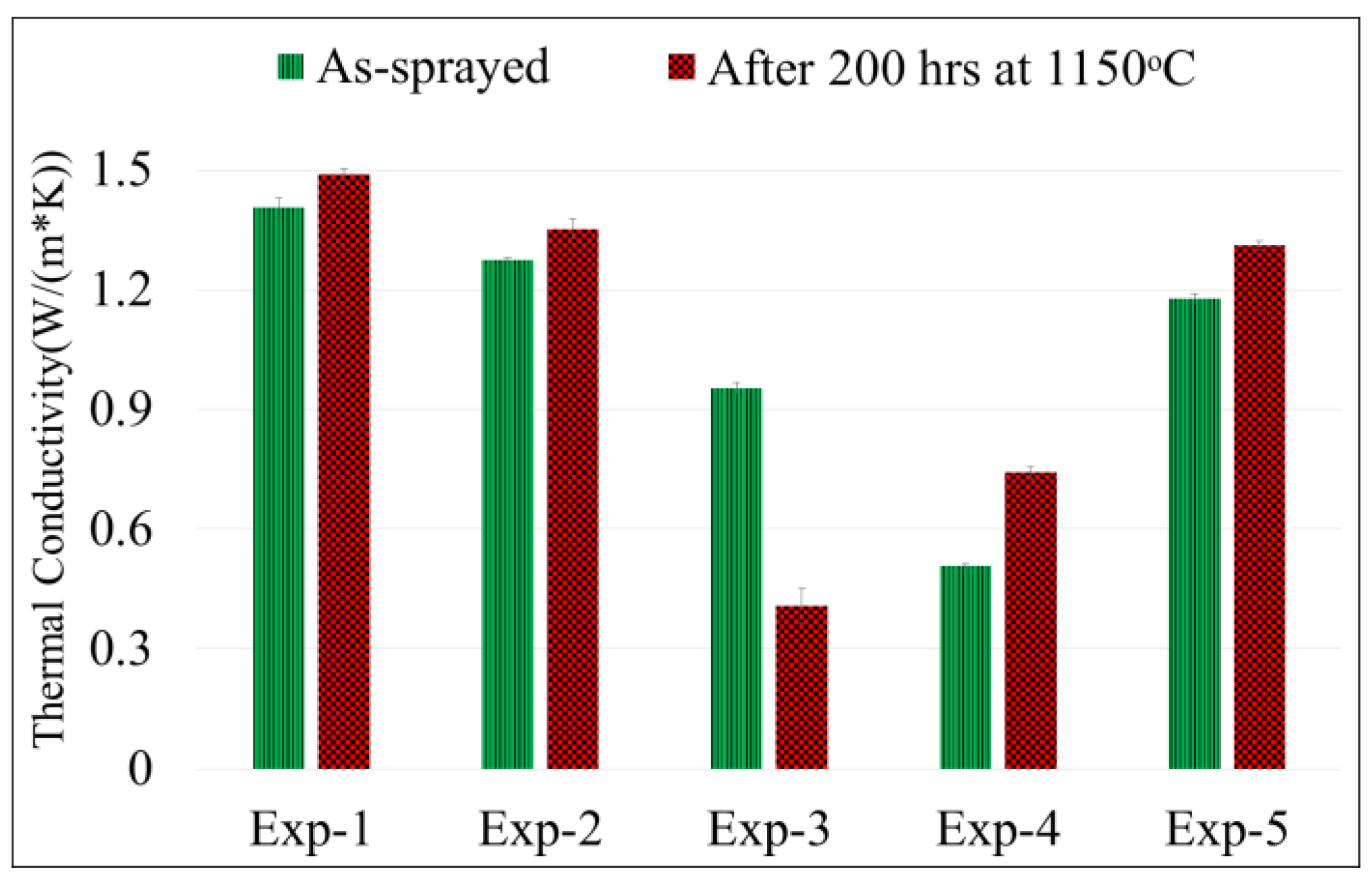
3.3. Effect of Microstructural Changes on Thermal Conductivity

As discussed in the previous section, accompanied sintering can potentially decrease the overall porosity and this can be accompanied by an increase in the thermal conductivity of the coating [22,30]. Such an increase in thermal conductivity is completely undesirable in gas turbine applications and, hence, TBCs with better sintering resistance are continuously sought. Coatings studied in this work, after heat treatment, showed both an increase and decrease in thermal conductivity also in some coatings it even remained unchanged. The results can be seen from Figure 10 where Exp-1 and Exp-2 have shown almost no change, Exp-4 and Exp-5 have shown a slight increase and Exp-3 has shown a significant decrease in the thermal conductivity after heat treatment.
Decrease in thermal conductivity by more than a 60% is not usually noticed in 8YSC TBCs. However, in this coating (i.e., Exp-3) the decrease can be attributed to the trade-off between the three microstructural changes (pore coarsening, sintering and crystallite size growth) as described in the previous section. More the scattering interfaces higher the phonon scattering and hence lower the thermal conductivity. That means pore coarsening which increases the porosity can decrease the thermal conductivity, sintering on the other hand decreases the porosity and hence can increase the thermal conductivity and crystallite size growth which reduces the grain boundary interfaces can also increase the thermal conductivity [20,22,24,26,44,45].
As showed in the previous section, coating Exp-3 has significantly higher change in the coarse porosity (pore coarsening i.e., about 138% increase in the coarse porosity), almost no change in the fine porosity (relatively lower sintering i.e., about 10% decrease in the fine porosity) and a relatively lower crystallite size growth (about 36% increase in crystallite size) compared to all other coatings. This suggests that in coating Exp-3 pore coarsening was the dominating microstructural change compared to sintering and crystallite size growth. This might thus be a reason for such an unusual decrease in thermal conductivity.
Figure 10 also illustrates that Exp1 and Exp-2 showed no change in thermal conductivity after heat treatment. This can be again correlated with their microstructural changes. Figure 4 and Figure 6 show that both coatings underwent a significant increase in coarse porosity (pore coarsening i.e., about 213% and 87% increase in coarse porosity for Exp-1 and 2 respectively) whereas Exp-1 has shown a significant decrease in fine porosity (sintering i.e., about 69% decrease in fine porosity) and Exp-2 did not show significant change in fine porosity (i.e., about 6% increase only). Both Exp-1 and Exp-2 have shown a significant increase in the crystallite size (i.e., 60% and 55% increase in crystallite size for Exp-1 and 2 respectively) after heat treatment as seen in Figure 9.
Exp-1 underwent all three microstructural changes mentioned above hence it can be said that its thermal conductivity is the trade-off of the increase in thermal conductivity due to sintering and crystallite size growth and decrease in thermal conductivity due to pore coarsening. This might have resulted in similar overall thermal conductivity as before and after heat treatment. Exp-2 on the other hand has shown pore coarsening and crystallite size growth but negligible sintering. Thus, in Exp-2 the thermal conductivity might have been a balance between the increase due to the crystallite size growth and decrease due to the pore coarsening.
Comparing coatings Exp-3 and Exp-4, an interesting thing which can be noticed is that even though the total porosity content for both coatings after heat treatment was almost similar, the thermal conductivity for Exp-4 is about double than that of Exp-3. This clearly suggests that it is not only the total porosity content but other factors which have to be taken care of while discussing the thermal conductivity of such coatings. Some of these factors as discussed above based on the observations can be the extent of fine pores, coarse pores and crystallite size and also the respective changes in all three after the heat treatment. Comparing the changes in crystallite size, coarse porosity and fine porosity for Exp-3 and Exp-4 it can be observed that Exp-4 has shown about 113% increase in crystallite size whereas Exp-3 showed an increase of about 36% only. In addition, a decrease in coarse porosity for Exp-4 of about 38% was noticed compared to Exp-3 where an increase of about 138% was observed. In addition, Exp-4 also showed higher decrease in fine porosity which was about 40% compared to Exp-3 which was about 10% only.
The comparison between Exp-3 and Exp-4 hence clearly reveals that the significantly higher increase in crystallite size for Exp-4, lower increase, in fact in this case it was a decrease for coarse porosity and higher decrease in fine porosity where all of these changes resulting in lesser phonon scattering interfaces might have resulted in higher thermal conductivity (almost more than the double) for Exp-4.
Finally, comparing Exp-4 and Exp-5, a significant increase in thermal conductivity for both was noticed which can also be explained using the similar understanding as discussed above, that it is a trade-off between the three microstructural changes. Coarse porosity was significantly decreased in Exp-4 (i.e., about 38% decrease) (Figure 4) whereas in Exp-5 it slightly increased (i.e., about 27% increase) (Figure 4) after heat treatment. On the other hand both fine porosity (Figure 6) and crystallite size (Figure 9) were significantly decreased (sintering, i.e., about 41% for Exp-4 and 52% for Exp-5 decrease) and increased (crystallite size growth, i.e., about 113% for Exp-4 and 66% for Exp-5 increase) respectively for both coatings. Thus, in both coatings sintering and crystallite size growth effect could be more dominant than the pore coarsening effect, which might be the reason for significantly higher thermal conductivity observed after heat treatment.

4. Summary and Conclusion

An image analysis technique was adapted in this work to analyze the porosity of suspension plasma sprayed thermal barrier coatings. In this work unlike conventional image analysis two extreme magnifications i.e., low (×500) and high (×10,000) which can consider varied scaled porosity typically observed in SPS TBCs from fine nano-sized to coarse micron sized pores and cracks was utilized. It was found that this two magnification approach can be beneficial to analyze porosity of coatings with varied scaled porosity (especially when the samples are heat treated) if the magnification used for analysis is adapted to the different pore sizes.
Total porosity in 8YSZ ASPS sprayed ceramic top coats (TBCs) not only decreased as expected in a conventional APS TBCs after heat treating at 1150 °C for 200 h in Argon but also increased. Specifically three different microstructural changes were noticed namely pore coarsening, sintering and crystallite size growth in almost all coatings. The increase in porosity was attributed to pore coarsening, i.e., coarser pores (at about larger than 1 µm2) more specifically due to the widening of the inter-columnar spacing and coalescence of pores. It was found that it is a trade-off between these three microstructural changes which can decide the overall trend in thermal conductivity of the respective coating. If the pore coarsening dominated the sintering and crystallite size growth then the overall coating thermal conductivity was observed to be decreased significantly.

Acknowledgments

The authors would like to acknowledge Nicolas Curry and Stefan Björklund for helping out with the spraying of coatings. Authors are thankful to Zdenek Pala and Toni Bogdanoff, for support in conducting the XRD experiment (as well as in analyzing the results) & LFA measurements respectively. Additionally, authors would like to thanks an Internship student Narayanan Venkateswaran for capturing the SEM micrographs and performing the image analysis. Finally, authors would also like to thank Västra Götalands Regionen (VGR), Sweden for funding the research work through a project “PROSAM”.

Author Contributions

Ashish Ganvir conceived and designed the experiments under the supervision of Nicolaie Markocsan. The sample preparation and microstructure analysis using SEM, thermal diffusivity measurement and data analysis was carried out by Ashish Ganvir. The paper was written by Ashish Ganvir under the supervision of Shrikant Joshi and Nicolaie Markocsan.

Conflicts of Interest

The authors declare no conflict of interest.

References

  1. Miller, R.A. Current status of thermal barrier coatings—An overview. Surf. Coat. Technol. 1987, 30, 1–11. [Google Scholar] [CrossRef]
  2. Miller, R.A. Thermal barrier coatings for aircraft engines: History and directions. J. Therm. Spray Technol. 1997, 6, 35–42. [Google Scholar] [CrossRef]
  3. Sirignano, W.A.; Liu, F. Performance increases for gas-turbine engines through combustion inside the turbine. J. Propuls. Power 1999, 15, 111–118. [Google Scholar] [CrossRef]
  4. Schulz, U.; Leyens, C.; Fritscher, K.; Peters, M.; Saruhan-Brings, B.; Lavigne, O.; Dorvaux, J.-M.; Poulain, M.; Mévrel, R.; Caliez, M. Some recent trends in research and technology of advanced thermal barrier coatings. Aerosp. Sci. Technol. 2003, 7, 73–80. [Google Scholar] [CrossRef]
  5. Wang, C.-L.; Hwang, W.-S.; Chu, H.-L.; Yen, F.-L.; Hwang, C.-Y.; Hsi, C.-S.; Lee, H.-E.; Wang, M.-C. Phase transformation and crystalline growth of 4 mol% yttria partially stabilized zirconia. J. Sol-Gel Sci. Technol. 2014, 70, 428–440. [Google Scholar] [CrossRef]
  6. Levi, C.G. Emerging materials and processes for thermal barrier systems. Curr. Opin. Solid State Mater. Sci. 2004, 8, 77–91. [Google Scholar] [CrossRef]
  7. Curry, N.; Markocsan, N.; A–stergren, L.; Li, X.-H.; Dorfman, M. Evaluation of the lifetime and thermal conductivity of dysprosia-stabilized thermal barrier coating systems. J. Therm. Spray Technol. 2013, 22, 864–872. [Google Scholar] [CrossRef]
  8. Schulz, U.; Bernardi, O.; Ebach-Stahl, A.; Vassen, R.; Sebold, D. Improvement of EB-PVD thermal barrier coatings by treatments of a vacuum plasma-sprayed bond coat. Surf. Coat. Technol. 2008, 203, 160–170. [Google Scholar] [CrossRef]
  9. Kakuda, T.R.; Limarga, A.M.; Bennett, T.D.; Clarke, D.R. Evolution of thermal properties of EB-PVD 7YSZ thermal barrier coatings with thermal cycling. Acta Mater. 2009, 57, 2583–2591. [Google Scholar] [CrossRef]
  10. Renteria, A.F.; Saruhan, B.; Schulz, U.; Raetzer-Scheibe, H.-J.; Haug, J.; Wiedenmann, A. Effect of morphology on thermal conductivity of EB-PVD PYSZ TBCs. Surf. Coat. Technol. 2006, 201, 2611–2620. [Google Scholar] [CrossRef]
  11. Curry, N.; Markocsan, N.; Li, X.-H.; Tricoire, A.; Dorfman, M. Next generation thermal barrier coatings for the gas turbine industry. J. Therm. Spray Technol. 2011, 20, 108–115. [Google Scholar] [CrossRef]
  12. VanEvery, K.; Krane, M.J.M.; Trice, R.W.; Wang, H.; Porter, W.; Besser, M.; Sordelet, D.; Ilavsky, J.; Almer, J. Column formation in suspension plasma-sprayed coatings and resultant thermal properties. J. Therm. Spray Technol. 2011, 20, 817–828. [Google Scholar] [CrossRef]
  13. Kassner, H.; Siegert, R.; Hathiramani, D.; Vassen, R.; Stover, D. Application of suspension plasma spraying (SPS) for manufacture of ceramic coatings. J. Therm. Spray Technol. 2008, 17, 115–123. [Google Scholar] [CrossRef]
  14. Killinger, A.; Gadow, R.; Mauer, G.; Guignard, A.; Vassen, R.; Stover, D. Review of new developments in suspension and solution precursor thermal spray processes. J. Therm. Spray Technol. 2011, 20, 677–695. [Google Scholar] [CrossRef]
  15. Guignard, A.; Mauer, G.; Vassen, R.; Stover, D. Deposition and characteristics of submicrometer-structured thermal barrier coatings by suspension plasma spraying. J. Therm. Spray Technol. 2012, 21, 416–424. [Google Scholar] [CrossRef]
  16. Ganvir, A.; Curry, N.; Markocsan, N.; Nylén, P.; Joshi, S.; Vilemova, M.; Pala, Z. Influence of microstructure on thermal properties of axial suspension plasma-sprayed YSZ thermal barrier coatings. J. Therm. Spray Technol. 2015, 25, 202–212. [Google Scholar] [CrossRef]
  17. Ganvir, A.; Curry, N.; Markocsan, N.; Nylén, P.; Toma, F.-L. Comparative study of suspension plasma sprayed and suspension high velocity oxy-fuel sprayed YSZ thermal barrier coatings. Surf. Coat. Technol. 2015, 268, 70–76. [Google Scholar] [CrossRef]
  18. Ganvir, A.; Curry, N.; Markocsan, N.; Nylen, P.; Vilemova, M.; Pala, Z. Influence of Microstructure on Thermal Properties of Columnar Axial Suspension Plasma Sprayed Thermal Barrier Coatings. In Proceedings of the International Thermal Spray Conference, Long Beach, CA, USA, 11–14 May 2015.
  19. Ganvir, A.; Curry, N.; Govindarajan, S.; Markocsan, N. Characterization of thermal barrier coatings produced by various thermal spray techniques using solid powder, suspension, and solution precursor feedstock material. Int. J. Appl. Ceram. Technol. 2015, 13, 324–332. [Google Scholar] [CrossRef]
  20. Ganvir, A.; Curry, N.; Björklund, S.; Markocsan, N.; Nylén, P. Characterization of microstructure and thermal properties of YSZ coatings obtained by axial suspension plasma spraying (ASPS). J. Therm. Spray Technol. 2015, 24, 1195–1204. [Google Scholar] [CrossRef]
  21. Bacciochini, A.; Montavon, G.; Ilavsky, J.; Denoirjean, A.; Fauchais, P. Porous architecture of SPS thick YSZ coatings structured at the nanometer scale (50 nm). J. Therm. Spray Technol. 2010, 19, 198–206. [Google Scholar] [CrossRef]
  22. Kassner, H.; Stuke, A.; Rodig, M.; Vassen, R.; Stover, D. Influence of Porosity on Thermal Conductivity and Sintering in Suspension Plasma Sprayed Thermal Barrier Coatings. In Advanced Ceramic Coatings and Interfaces III: Ceramic Engineering and Science Proceedings; Lin, H.-T., Zhu, D., Eds.; John Wiley & Sons: Hoboken, UK, 2009; Volume 29, pp. 147–158. [Google Scholar]
  23. Golosnoy, I.O.; Tsipas, S.A.; Clyne, T.W. An analytical model for simulation of heat flow in plasma-sprayed thermal barrier coatings. J. Therm. Spray Technol. 2005, 14, 205–214. [Google Scholar] [CrossRef]
  24. Curry, N.; Janikowski, W.; Pala, Z.; Vilémová, M.; Markocsan, N. Impact of impurity content on the sintering resistance and phase stability of dysprosia- and yttria-stabilized zirconia thermal barrier coatings. J. Therm. Spray Technol. 2013, 23, 160–169. [Google Scholar] [CrossRef]
  25. Curry, N.; VanEvery, K.; Snyder, T.; Markocsan, N. Thermal conductivity analysis and lifetime testing of suspension plasma-sprayed thermal barrier. Coatings 2014, 4, 630–650. [Google Scholar] [CrossRef]
  26. Deshpande, S. High temperature sintering and oxidation behavior in plasma sprayed TBCs (single splat studies) Paper 2—Relevance of variation in materials systems of TBC components. J. Surf. Eng. Mater. Adv. Technol. 2013, 3, 116–132. [Google Scholar] [CrossRef]
  27. Exner, H.E.; Müller, C. Particle rearrangement and pore space coarsening during solid-state sintering. J. Am. Ceram. Soc. 2009, 92, 1384–1390. [Google Scholar] [CrossRef]
  28. Siebert, B.; Funke, C.; Vassen, R.; Stover, D. Changes in porosity and Young’s Modulus due to sintering of plasma sprayed thermal barrier coatings. J. Mater. Process. Technol. 1999, 92, 217–223. [Google Scholar] [CrossRef]
  29. Cipitria, A.; Golosnoy, I.O.; Clyne, T.W. A sintering model for plasma-sprayed zirconia thermal barrier coatings. Part II: Coatings bonded to a rigid substrate. Acta Mater. 2009, 57, 993–1003. [Google Scholar] [CrossRef]
  30. Wang, K.; Peng, H.; Guo, H.; Gong, S. Effect of Sintering on Thermal conductivity and thermal barrier effects of thermal barrier coatings. Chin. J. Aeronaut. 2012, 25, 811–816. [Google Scholar] [CrossRef]
  31. Kumar, S.; Cocks, A.C.F. Sintering and mud cracking in EB-PVD thermal barrier coatings. J. Mech. Phys. Solids 2012, 60, 723–749. [Google Scholar] [CrossRef]
  32. Zhao, X.; Wang, X.; Xiao, P. Sintering and failure behaviour of EB-PVD thermal barrier coating after isothermal treatment. Surf. Coat. Technol. 2006, 200, 5946–5955. [Google Scholar] [CrossRef]
  33. Lughi, V.; Tolpygo, V.K.; Clarke, D.R. Microstructural aspects of the sintering of thermal barrier coatings. Mater. Sci. Eng. A 2004, 368, 212–221. [Google Scholar] [CrossRef]
  34. Wigren, J. High Insulation Thermal Barrier Systems–HITS, Brite Euram Project BE96–3226, 1996.
  35. Rietveld, H.M. Line profiles of neutron powder-diffraction peaks for structure refinement. Acta Crystallogr. 1967, 22, 151–152. [Google Scholar] [CrossRef]
  36. Yashima, M.; Sasaki, S.; Kakihana, M.; Yamaguchi, Y.; Arashi, H.; Yoshimura, M. Oxygen-induced structural change of the tetragonal phase around the tetragonal–cubic phase boundary in ZrO2–YO1.5 solid solutions. Acta Crystallogr. B 1994, 50, 663–672. [Google Scholar] [CrossRef]
  37. Curry, N.; Donoghue, J. Evolution of thermal conductivity of dysprosia stabilised thermal barrier coating systems during heat treatment. Surf. Coat. Technol. 2012, 209, 38–43. [Google Scholar] [CrossRef]
  38. Taylor, R. Thermal conductivity determinations of thermal barrier coatings. Mater. Sci. Eng. A 1998, 245, 160–167. [Google Scholar] [CrossRef]
  39. Cernuschi, F.; Lorenzoni, L.; Ahmaniemi, S.; Vuoristo, P.; Mäntylä, T. Studies of the sintering kinetics of thick thermal barrier coatings by thermal diffusivity measurements. J. Eur. Ceram. Soc. 2005, 25, 393–400. [Google Scholar] [CrossRef]
  40. Krishnamurthy, R.; Srolovitz, D.J. Sintering and microstructure evolution in columnar thermal barrier coatings. Acta Mater. 2009, 57, 1035–1048. [Google Scholar] [CrossRef]
  41. Zotov, N.; Bartsch, M.; Chernova, L.; Schmidt, D.A.; Havenith, M.; Eggeler, G. Effects of annealing on the microstructure and the mechanical properties of EB-PVD thermal barrier coatings. Surf. Coat. Technol. 2010, 205, 452–464. [Google Scholar] [CrossRef]
  42. Schulz, U.; Fritscher, K.; Leyens, C.; Peters, M. High-Temperature Aging of EB-PVD Thermal Barrier Coating; John Wiley & Sons, Inc.: Chichester, UK, 2001; pp. 347–356. [Google Scholar]
  43. Kingery, W.D.; Francois, B. The Sintering of Crystalline Oxides, I. Interactions between Grain Boundaries and Pores. In Sintering Key Papers; Sōmiya, S., Moriyoshi, Y., Eds.; Springer: Berlin, Germany, 1990; pp. 449–466. [Google Scholar]
  44. Carpio, P.; Blochet, Q.; Pateyron, B.; Pawlowski, L.; Salvador, M.D.; Borrell, A.; Sanchez, E. Correlation of thermal conductivity of suspension plasma sprayed yttria stabilized zirconia coatings with some microstructural effects. Mater. Lett. 2013, 107, 370–373. [Google Scholar] [CrossRef]
  45. Latka, L.; Goryachev, S.B.; Kozerski, S.; Pawlowski, L. Sintering of fine particles in suspension plasma sprayed coatings. Materials 2010, 3, 3845–3866. [Google Scholar] [CrossRef]
Figure 1. A schematic of a typical thermal barrier coating system showing all the layers which are from the top-bottom: Ceramic top coat, Metallic bond coat and Substrate.
Coatings 07 00004 g001
Figure 2. A schematic of the two-magnification image analysis procedure adopted in this work.
Coatings 07 00004 g002
Figure 3. Total Porosity content in % area for all five coatings before and after heat treatment.
Coatings 07 00004 g003
Figure 4. Coarse porosity content in % area for all coatings before and after heat treatment.
Coatings 07 00004 g004
Figure 5. SEM micrograph of the cross-section of coating Exp-3 (a) at lower magnification showing the coarse porosity before (up) and after (down) heat treatment confirming the pore coarsening (widening of inter-columnar spacing). In addition, similar SEM micrograph of coating Exp-4 (b) showing no as significant change as in in Exp-3 in intercolumnar spacing and decrease in some coarse porosity within the columns.
Coatings 07 00004 g005
Figure 6. Fine porosity content in % area for all coatings before and after heat treatment.
Coatings 07 00004 g006
Figure 7. SEM micrograph of the cross-section of coating Exp-4 (a,b) at high magnification showing the fine porosity before (a,c) and after (b,d) heat treatment and hint of coalescence and densification of pores is also shown. In addition, similar micrograph of coating Exp-2 (c,d) showing no as significant change as in coating Exp-4 in the fine porosity.
Coatings 07 00004 g007aCoatings 07 00004 g007b
Figure 8. Crystallite phase analysis performed by XRD for all five coatings before and after heat treatment showing no phase change.
Coatings 07 00004 g008
Figure 9. Crystallite size measured by XRD for all coatings before and after heat treatment.
Coatings 07 00004 g009
Figure 10. Thermal conductivity results for all five coatings before and after heat treatment showing an unusual significant decrease in Exp-3.
Coatings 07 00004 g010
Table 1. Five different coatings studied in this work and spray parameters used to produce them [16].
Spraying ParameterFive Different Coatings Studied in This Work
Exp-1Exp-2Exp-3Exp-4Exp-5
Suspension feed rate (mL/min)70454510045
Total power during spray (kW)125101124124116
Surface speed (cm/s)145.57575216216
Spray distance (mm)7550100100100
Total gas flow rate (L/min)250200300300200

