1. Introduction
Particle based films mean alternative coatings, consisting of a carrying matrix, different filler material, e.g., conductive particles, fibers, nanotubes, and nanoparticles, etc., which are distributed in a matrix by adding additional solvents [
1,
2,
3,
4,
5]. The functional purpose of the particle based films defines the physical and mechanical properties they should possess and determines a suitable method for their application to the desired surface e.g., printing, spraying, and spin-coating techniques [
6] as well as physical vapor deposition (PVD) [
7], resin transfer molding (RTM) [
8] and other molding methods (e.g., compression, vacuum, resin injection) [
9], etc.
According to the diversity of the application method and the distinguishing feature of particle based films to combine properties from both filler material and carrying matrix [
10,
11] they have been successfully implemented in industry and are presently an important part of various designs. They are applied for example by conductive paste printing in integrated circuits, manufacturing of Li-ion batteries or solar cells [
12]. Recently particle based films were also used in the 3D printing technique [
13]. Particularly important are particle based films for aircraft, wind power and the automotive industry being incorporated onto the surface of composite structures, e.g., carbon or glass fiber reinforced plastics (CFRP and GFRP), for protection against damage caused by a lightning strike [
11,
14]. This application area is principally the focus of our attention in this work.
When particle based films are used as a protection surface layer deposited onto composite structures in aircraft etc. it is very important that the electrical resistance of the films stays homogeneous in the coated area to avoid critical local current densities [
4,
5,
6,
7,
8,
9,
10,
11,
12,
13,
14,
15,
16,
17,
18]. This homogeneity defines the films quality. It is important to note that in aircraft and wind power industries big and convoluted shapes have to be coated by particle based films. Thus, it is either impossible to use some of the application methods (e.g., spin-coating) or the cost is high when applying films by high precision application techniques (PVD, RTM, etc.). Therefore, spraying or printing methods are more suitable for this purpose. In either case, defects in the films homogeneity can occur during their manufacturing and application, that can only be detected after the films curing process is finished, leading to undesirable financial and time costs. Therefore, an in-situ fast monitoring method is needed to provide an opportunity to predict the particle based films electrical resistance in a wet state whilst allowing adjustments.
According to the literature, many studies have been focused on finding inspection and monitoring methods for quality assurance of particle based films. Thus, in [
19] and in [
20] authors reported the successful application of terahertz conductivity measurements to monitor thin films with different filler content. However, this method is suitable for ultra-thin films with a thickness well below the skin depth. Hence, the method is not applicable for lightning protection films having a thickness in the micrometer range [
16]. Another work of Zhang [
20] illustrated application of the X-ray method to study the structure formation process of nanoparticle thin films. However, the method is more useful for stationary measurements and not for convoluted shapes requiring a quick-working portable method and also is expensive. The work by author Eslamian Morteza [
12] showed the study of the dynamics of the spray coating process by using microscope videos. However, in the case of optical methods, it is possible to detect defects only on the top of the layer and seems not to be suitable for films having a thickness higher than one micrometer. Moreover, only visual defects can be controlled by the method and not the conductivity of the film.
This work aimed to investigate the drying process of particle based films by monitoring their electrical resistance using a non-destructive HFEC spectroscopy, that works quickly, is noninvasive and therefore can be applied to wet as well as to dried films; working in a high-frequency range, it reacts to the smallest changes in electrical and dielectric properties of the particle based films [
5]. Furthermore, based on HFEC a portable measuring system can be developed to monitor the in-situ films drying process on big and convoluted shapes.
In order to validate the HFEC method for an in-situ monitor of particle based films electrical resistance, different types of films were produced, deposited on the dielectric substrate and CFRP and measured using the HFEC system based EddyCus® designed and manufactured by Fraunhofer IKTS (Dresden, Germany). The chemical composition of the films provided a drying process at room temperature and normal conditions, and each parameter could be varied, e.g., type of a filler, polymer matrix type or even coated area and thickness. Knowing exactly the composition of the particle based films it becomes possible to investigate the influence of different film parameters on their percolation behavior during curing in a slow drying motion mode without additional noises caused by temperature rise.
The results give an approach to monitor the films’ electrical resistance beginning from films which are in a liquid state until they are dried. Based on this, an algorithm is developed, allowing prediction of the final electrical resistance of the particle based films throughout the drying process, which makes it possible to monitor the in-situ particle based films electrical resistance. This algorithm was successfully implemented in a prototype system based on the EddyCus® HFEC device platform presented in this work. This prototype is the first solution for a portable system allowing measuring on huge and uneven surfaces.
2. Materials and Methods
2.1. HFEC
Typically, eddy current (EC) equipment consists of an electronic oscillator (i.e., generator), electronics, and a coil or combination of a coil to give a transmitting and a pickup coil. The signal from the receiving coil is analyzed, which is influenced by the samples’ properties. For standard EC the electrical properties of a sample are recorded as variations in the complex impedance plane of the transmitting coil, caused by variations in the dispersion of the magnetic field and electrical circular currents in the sample. An electronic oscillator generates an alternating current that passes through a transmitting coil and causes a primary magnetic field
B with magnetic flux Φ
B which is given in Equation (1). When Φ
B changes because
B changes, Faraday’s law states that the electromotive force is acquired, which is given in Equation (2) as
Uind [
21,
22,
23,
24].
When the conductive sample is placed in the impact zone of the coil, eddy currents
J and displacement currents
JD are generated in the sample (Equation (3)) causing the secondary magnetic field to try and counteract the primary magnetic field and change it. Whereas the higher the frequency of excitation the stronger are the displacement currents expressed [
24]. The ability of HF EC to excite the displacement currents shows its advantage over a standard Eddy Current (EC).
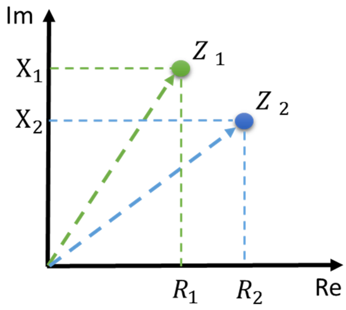
The measured difference of induced voltage is thereafter represented in the complex impedance plane as real and imaginary parts. Whereby, the real part corresponds to the active resistance
R and the imaginary part expresses reactance
X of the material. The impedance
Z is calculated as given in Equation (4):
Figure 1 illustrates how change of resistance and reactance of the material shifts the work point obtained by EC measurements in the complex impedance plane from
Z1 to
Z2. This effect can be used for monitoring the change of the material properties as a function of time.
2.2. Particle Based Films
Particle based films consist of a carrier matrix and a filling material in the form of particles. The type of the film, dielectric or electrical, is defined by the type and concentration of particles in a carrying matrix. In this work films based on conductive particles are considered. In this case, it should be considered that their electrical resistance changes during drying [
25,
26,
27,
28].
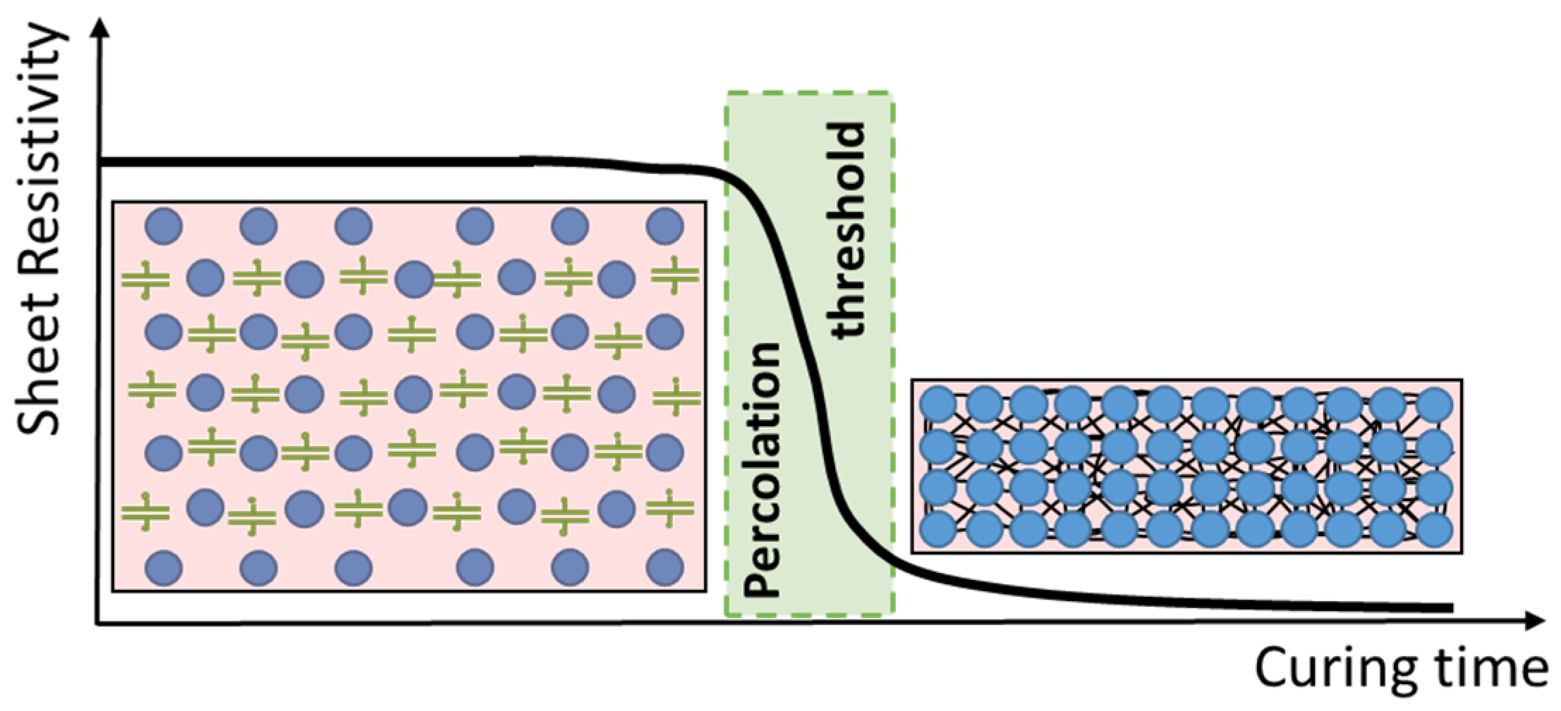
Figure 2 demonstrates schematically the drying process of particle based films.
After deposition, the distance between particles is large due to the presence of the chemicals used to make possible the mixing together of particles and epoxy. The electrical resistance is high. This is represented in
Figure 2 as the amount of capacitors between particles before the percolation threshold. We represented the capacitors to show that before the percolation threshold, the dielectric properties of particles change when the electro-magnetic field is applied, due to polymerization and permittivity changes. During drying, chemicals evaporate and particles become closer to each other, whereas the film shrinks. When particles are in contact with each other the film’s conductivity appears. The time at which this effect occurs is called the percolation threshold [
29]. After the percolation threshold is reached the thickness does not change anymore and the polymerization process of the epoxy has started.
To enable monitoring of the overall drying process of particle based films a method allowing the measurements of not only electrical (electrical resistance) but also dielectric (capacitance) properties should be selected, which is possible by the HFEC method proposed in this work.
2.3. Sample Preparation
Particle based films were mixed at room temperature and under normal conditions. First, the polymer resin and the hardener were mixed together in the mass ratio of 4:1 respectively according to the specification. Thereafter the coupling and the solvent agent were added and the mixture was stirred for 10 min to blend. After adding conductive particles, the mixture was mixed for a further 10 min.
Table 1 provides information about the composition of particle based films.
The epoxy system ensures a total drying time of the particle based films of 24 h at room temperature. The solvent is well dissolved with this type of epoxy and evaporates before the polymer matrix polymerization begins. The coupling agent is added to the mixture to improve the particle dispersion in the matrix adhesive [
30].
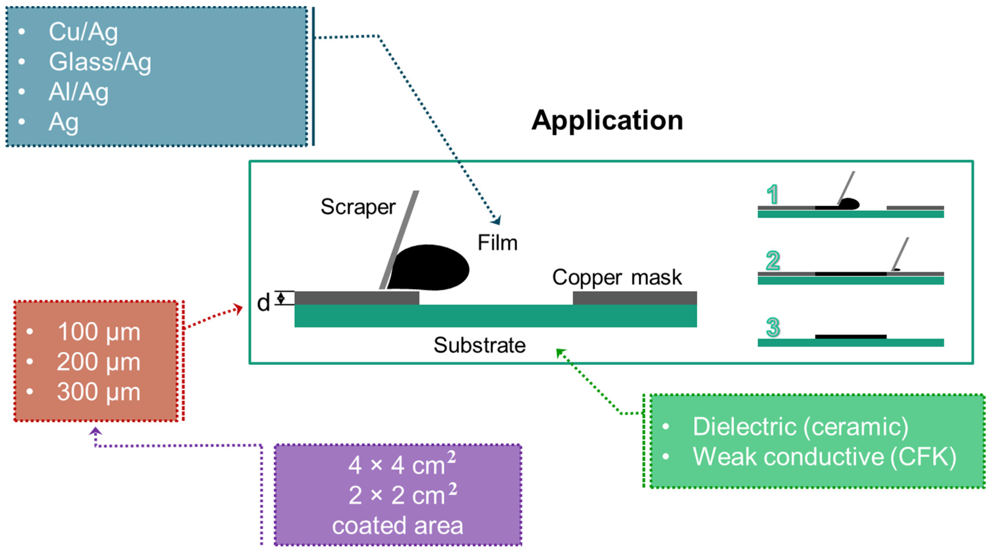
After preparation, wet conductive coatings were deposited onto the substrate using the frame printing technique [
31] by varying the next parameter: Type of conductive particles, the thickness of the frame, the coated area, and the type of substrate (
Figure 3).
Four types of particles were used in this work and are listed in
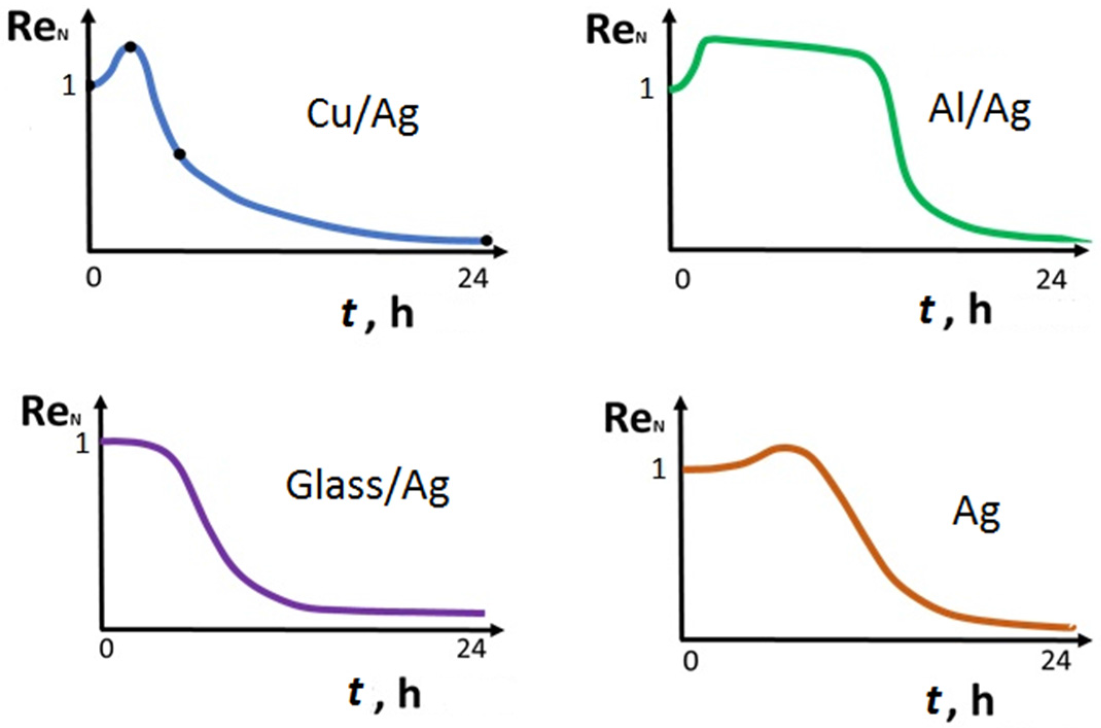
Table 2 below. The Cu/Ag particle provide the lowest resistance of the film after drying and the glass/Ag particle provide the highest resistance.
Three masks were used for films deposition having a thickness of 100, 200, and 300 µm. The initial thickness of the deposited films depends on the mask thickness and reduces during drying because of shrinkage. Each used copper frame has a rectangular opening of 40 mm × 40 mm and 20 mm × 20 mm, etched in the center; with this, the coated area is provided. Varying the coated area is especially important for HFEC measurements to investigate the influence of the edge effects on the measurements.
Two types of substrates were used in this work:
Ceramic Al2O3: Length 68 mm, width 68 mm, thickness 0.63 mm;
CFRP: Length 68 mm, width 68 mm, thickness 5 mm.
Ceramic substrate is used as it does not have its own conductivity and the HFEC measurements are influenced only by the changes in particle based films. Knowing the drying behavior of the particle based films on a ceramic substrate, the influence of the CFRP substrate on HFEC measurements can be estimated.
2.4. HFEC Measurements on Particle Based Films
After deposition, the particle based films are placed within a range of HFEC emission and measurements start immediately. The distance between the sensor and the film is 100 µm and measurements are performed at 30 s intervals over 24 h (from the beginning to the end of the drying).
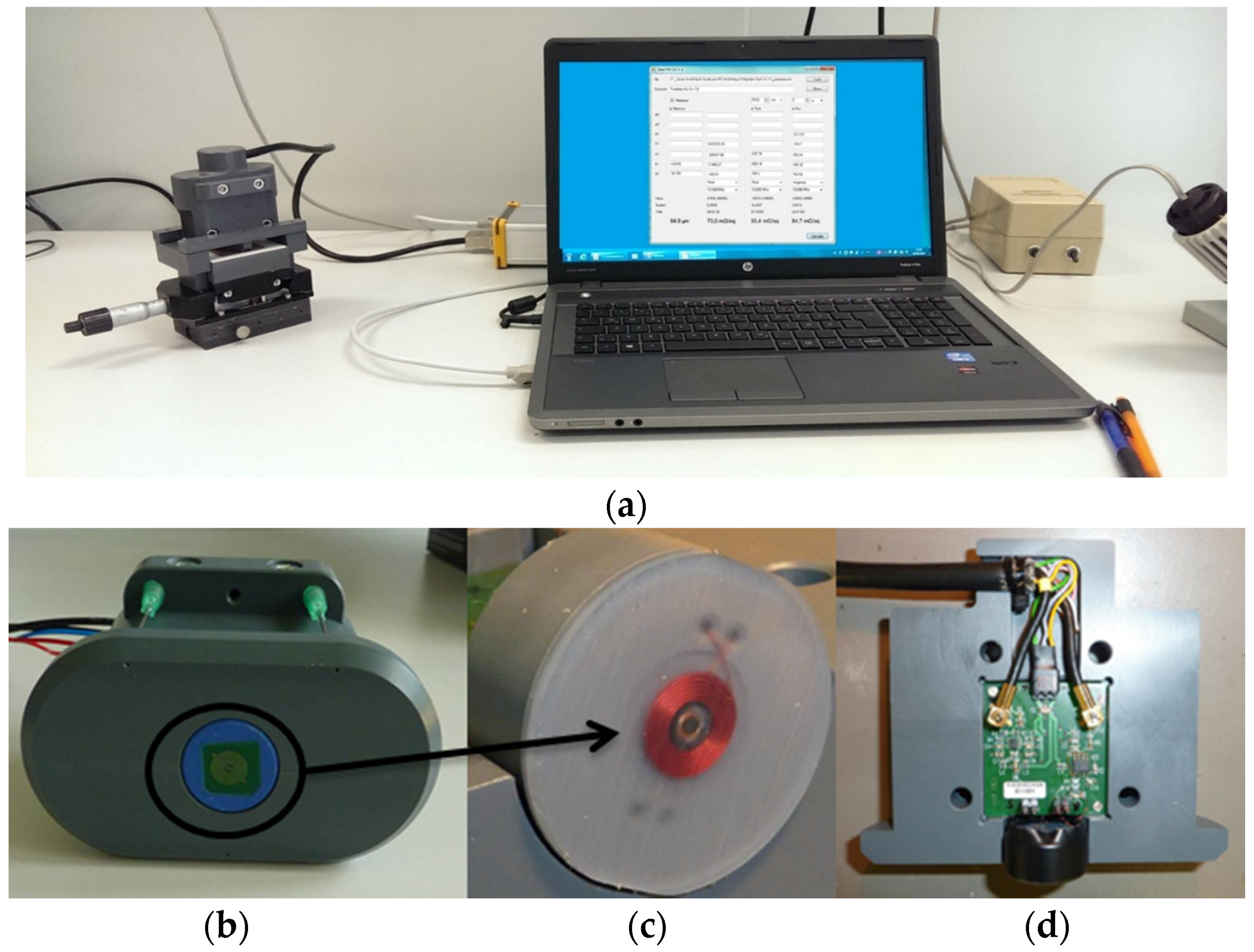
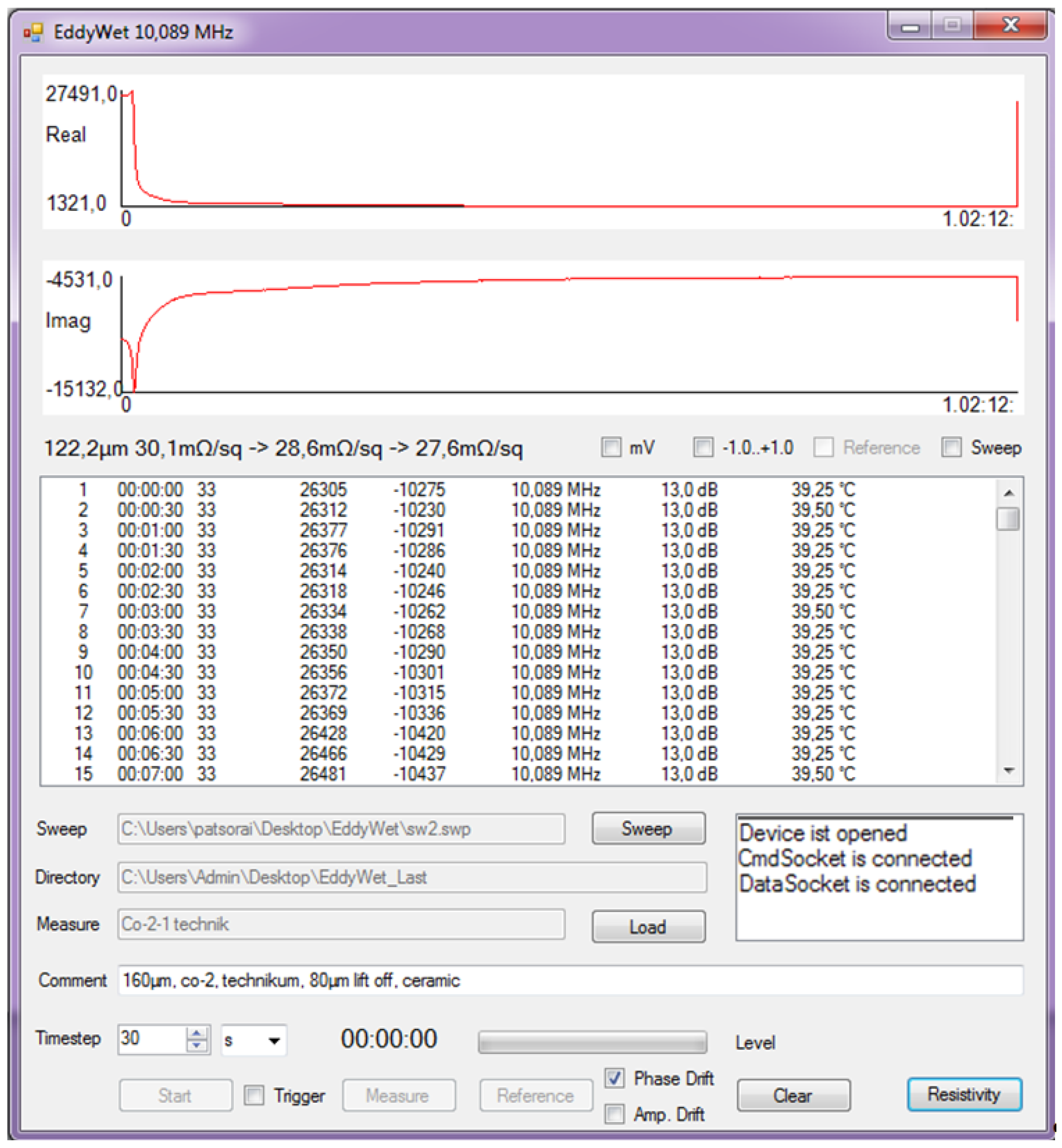
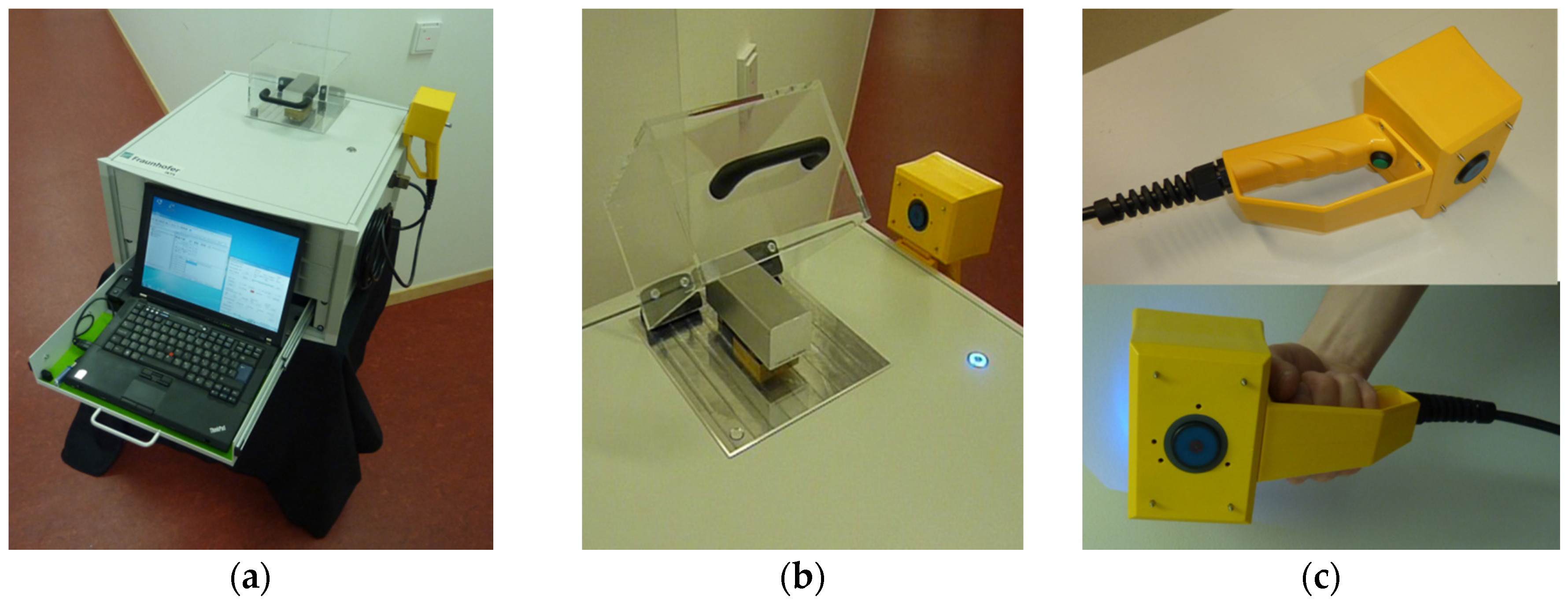
The HFEC system used for the measurements is shown in
Figure 4. It consists of a Laptop with installed software EddyWet 2.0 (Fraunhofer IKTS, Dresden, Germany), electronics, and sensor with two axial coils (
Figure 4a). The sensor-box is shown in
Figure 4b. The transmission coil is wound inside the ferrite cap and the pick-up coil outside of the cap so that the electromagnetic flux does not influence directly the pick-up coil (
Figure 4c). The preamplifier is located close to the coil inside the sensor-box (
Figure 4d) to stabilize the signal and to reduce the parasitic effects of stray fields and similar effects.
2.5. Reference Measurements
Due to the manual application process, the thickness of the coatings deviates from the desired value. Therefore, additional measurements on the films, called the reference, were performed and used by the analysis.
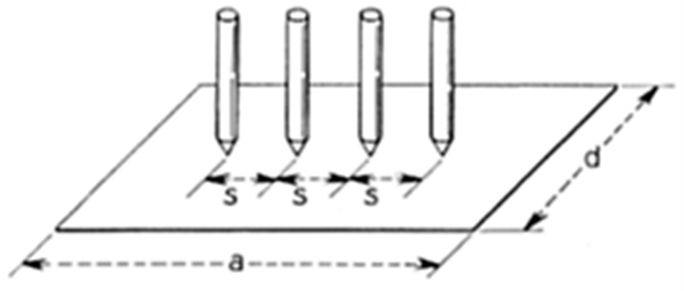
The electrical resistance of the dried samples was measured by the four-point probe method in the center of each coating using the multimeter consisting of a 2182A nanovoltmeter and 6221 DC and AC current source. In accordance with the geometry of the coated area and distance between the electrodes, the sheet resistivity, which is commonly used to characterize thin films [
32],
is calculated as given by Equation (5) [
33]:
where
V/
I is a measured value,
C is the correction factor for various geometries
(
;
).
Figure 5 shows parameters
a,
d, and
s for a rectangular geometry.
In this particular case s = 2 mm. This gives a correction factor for 4 cm × 4 cm geometry c = 4.4516 and for the geometry of 2 cm × 2 cm c = 4.2209.
The thickness of the film
d (in cm) and its electrical resistance ρ (in Ω·cm) are related to the calculated
Rs as given by Equation (6):
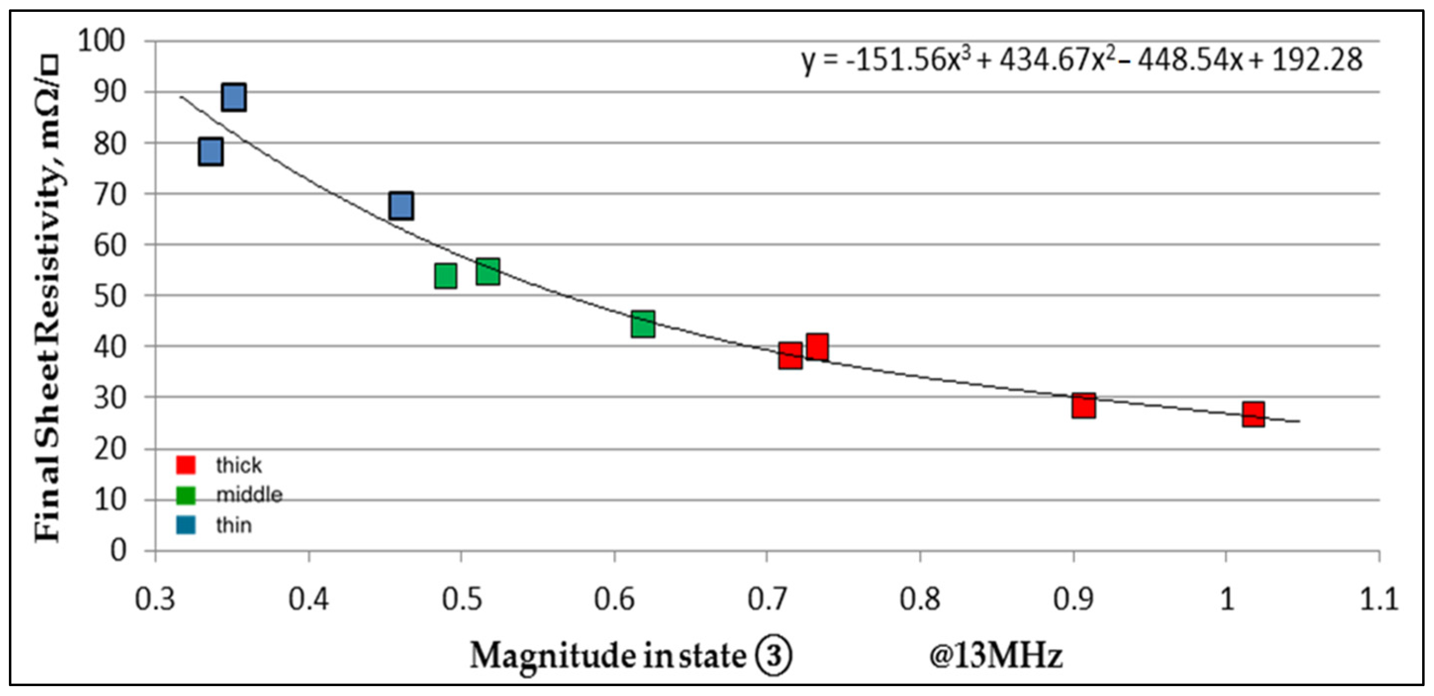
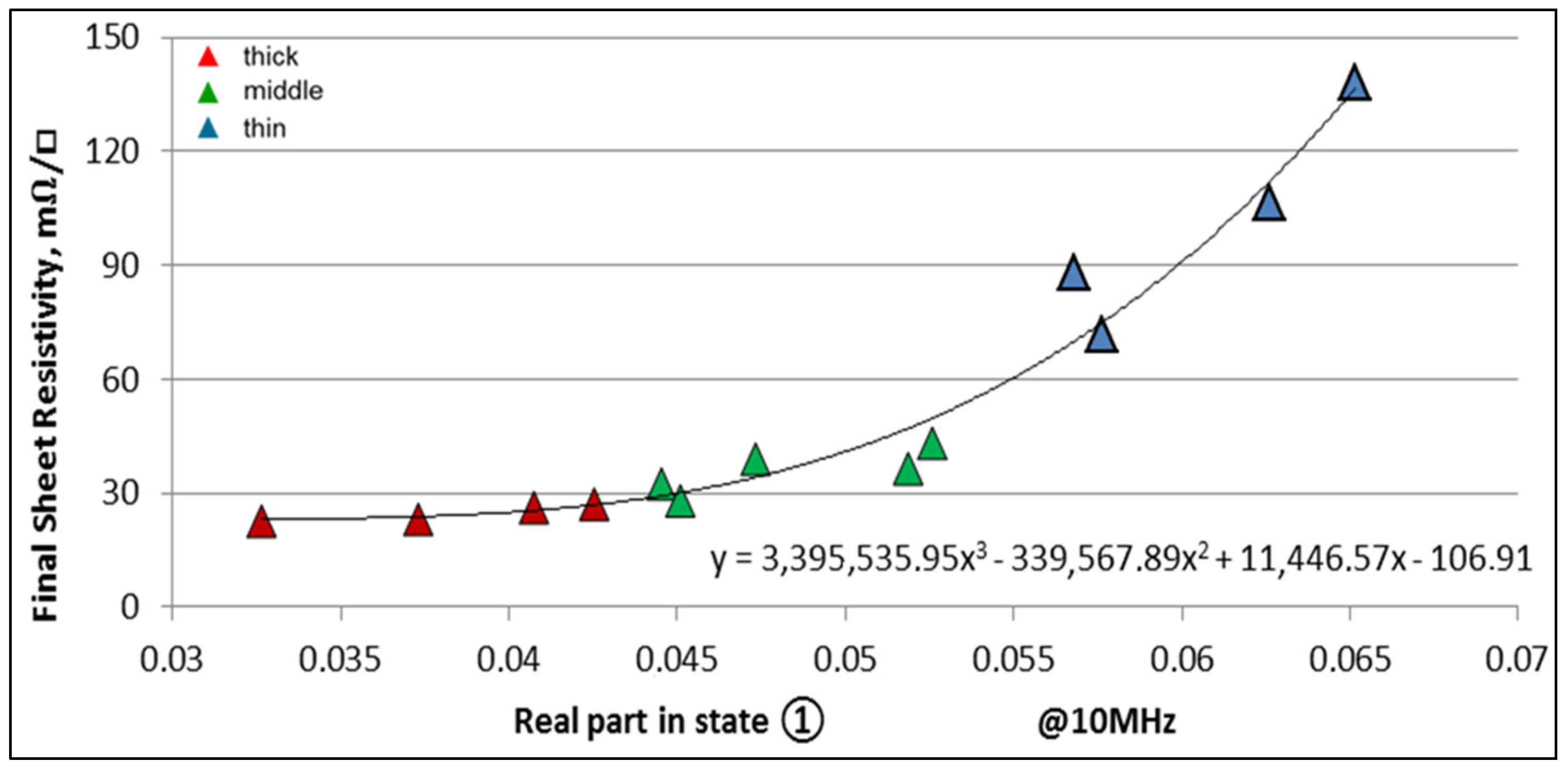
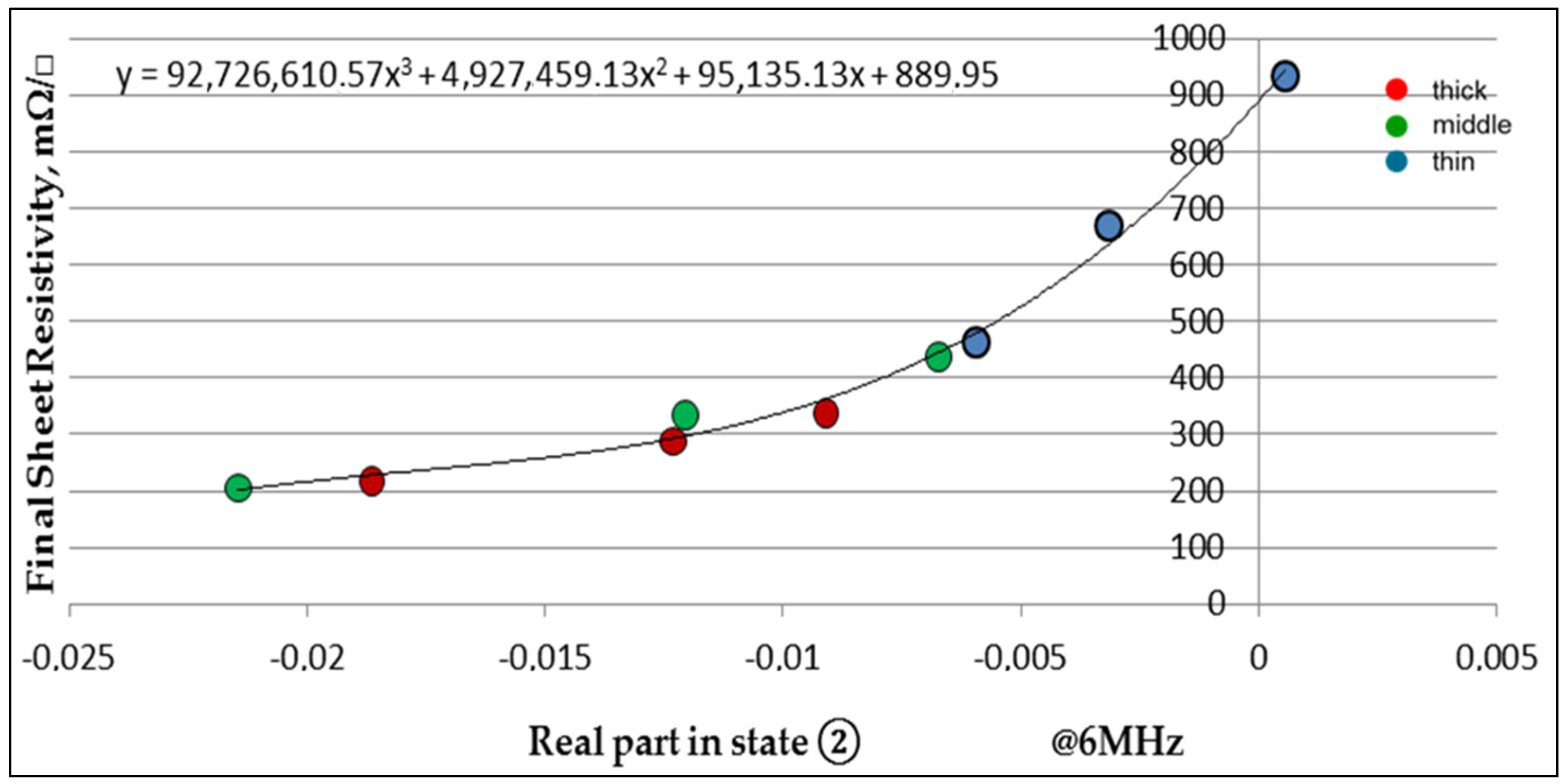
In the literature, the units of
Rs are ohm per square or Ω/sq. which is given on the graphs (Figures 8–16) as Ω/□ [
32].
4. Conclusions
Results of this work show that it is possible to analyze and to monitor the overall drying process of particle based films by using HFEC spectroscopy. Based on results it is possible to state that films based on different particles and deposited with a different coated area or on the conductive substrate providing their own drying behavior, can be monitored in the wet state as well as after the drying process has finished. The HFEC reacts to the smallest changes in the film. This is an approach not only to monitor films resistivity in-situ but also to manufacture films with predetermined properties, which would be relatively easily accessed by HFEC or to control which type of particles could be used in films as well as to determine the quality of the particles or even the age of the coating. Another approach would be also the usage of HFEC spectroscopy to monitor nanosized particle based films drying behaviors. This would require additional experiments to be performed.
Based on the results, an algorithm was developed and described in this paper allowing the prediction of the final parameters of particle based films in a wet state. An HFEC testing system for special issues in surface analysis was developed. The system is comprised of two special HFEC sensors, PC, electronics, and software based on a multi-frequency algorithm.
The next step is aligned to develop a mathematical model allowing description of the processes occurring during drying in particle based films even without performing supplementary references.


