Article

Low Group Delay Dispersion Optical Coating for Broad Bandwidth High Reflection at 45° Incidence, P Polarization of Femtosecond Pulses with 900 nm Center Wavelength

1
Sandia National Laboratories, P. O. Box 5800, MS 1197, Albuquerque, NM 87185, USA
2
STFC—Science and Technology Facilities Council, Rutherford Appleton Laboratory, Chilton, Didcot, Oxon, OX11 0QX, UK
*
Author to whom correspondence should be addressed.
Coatings 2016, 6(1), 11; https://doi.org/10.3390/coatings6010011
Submission received: 16 December 2015 / Revised: 19 February 2016 / Accepted: 2 March 2016 / Published: 9 March 2016
(This article belongs to the Special Issue Recent Advances in Optical Coatings)

Abstract

:
We describe an optical coating design suitable for broad bandwidth high reflection (BBHR) at 45° angle of incidence (AOI), P polarization (Ppol) of femtosecond (fs) laser pulses whose wavelengths range from 800 to 1000 nm. Our design process is guided by quarter-wave HR coating properties. The design must afford low group delay dispersion (GDD) for reflected light over the broad, 200 nm bandwidth in order to minimize temporal broadening of the fs pulses due to dispersive alteration of relative phases between their frequency components. The design should also be favorable to high laser-induced damage threshold (LIDT). We base the coating on TiO2/SiO2 layer pairs produced by means of e-beam evaporation with ion-assisted deposition, and use OptiLayer Thin Film Software to explore designs starting with TiO2/SiO2 layers having thicknesses in a reverse chirped arrangement. This approach led to a design with R > 99% from 800 to 1000 nm and GDD < 20 fs2 from 843 to 949 nm (45° AOI, Ppol). The design’s GDD behaves in a smooth way, suitable for GDD compensation techniques, and its electric field intensities show promise for high LIDTs. Reflectivity and GDD measurements for the initial test coating indicate good performance of the BBHR design. Subsequent coating runs with improved process calibration produced two coatings whose HR bands satisfactorily meet the design goals. For the sake of completeness, we summarize our previously reported transmission spectra and LIDT test results with 800 ps, 8 ps and 675 fs pulses for these two coatings, and present a table of the LIDT results we have for all of our TiO2/SiO2 BBHR coatings, showing the trends with test laser pulse duration from the ns to sub-ps regimes.

Graphical Abstract

1. Introduction

The specific focus of this study is the design of an optical coating that affords broad bandwidth high reflection (BBHR) of >99.5% for the 200-nm band from 800 to 1000 nm and for 45° angle of incidence (AOI) and P polarization (Ppol). Even more specifically, this BBHR coating must exhibit near linear group delay (GD) and near constant group delay dispersion (GDD) of the reflected light across this bandwidth, in order to reflect femtosecond (fs) laser pulses without distortion or broadening of their temporal profiles. Furthermore, our design and development of this BBHR coating is in the context of optical thin films that meet the challenging demands of high laser-induced damage threshold (LIDT) for large, meter-size optics of petawatt (PW) lasers like Sandia’s Z-Backlighter lasers [1,2,3]. These are kilojoule-class pulsed laser systems coupled to the Z-Accelerator [4,5], the most powerful and efficient X-ray source in the world. The large optics coating facility at Sandia specializes in the production of such high LIDT optical coatings for PW lasers [6,7]. Table 1 summarizes the BBHR coating design goals of this investigation.
Coatings that afford BBHR, high LIDT, and near constant GDD, play an essential enabling role for PW lasers with pulses in the fs regime. Variation with wavelength of the indices of refraction of the coating layers due to dispersion is significant over such broad bandwidths. Early research into ways of broadening the reflectivity bandwidth of multilayer coatings relied on using various progressions of the layer thicknesses to accommodate the different optical paths associated with a broad range of wavelengths [8,9]. This research did not explicitly take dispersion of the layer materials into account and did not attempt to control GDD of the reflected light.
The advent of fs-pulse lasers has drawn much attention to multilayer coatings as a means of controlling GD and GDD. A main line of research, which has been reviewed by Pervak [10], deals with coatings whose layer thicknesses result in different penetration depths into the coating for different wavelength components of light across broad, fs-pulse bandwidths. One purpose of these efforts is to compress frequency chirped pulses of nanosecond (ns) durations into fs-class pulses by means of reflection such that the different depths of penetration into the coating result in the different frequency components coalescing in time. For example, linear, chirped variation of layer thicknesses from the outer to inner layers, similar to the earlier work [8,9], led to a near linear increase of GD with wavelength [11].
Another direction of research into multilayer coatings for control of GD and GDD for fs pulses deals with coating structures which do not alter the relative phases between frequency components of the pulses on reflection. It is this direction that we are pursuing here. A significant contribution to this line of research is the work of J. Oliver et al. [12]. They have developed multilayer BBHR coatings that are suitable for deposition on meter-size optics and afford LIDT and GDD properties of the sort we are interested in achieving. Their approach for 45° AOI involves all-dielectric coating layers for S polarization (Spol) and a mixture of dielectric and metal coating layers for Ppol. Our approach, on the other hand, depends solely on dielectric coating layers, and has the advantage that a single BBHR coating handles both Spol and Ppol situations.
Our BBHR coating design considerations are guided by the properties of quarter-wave HR coatings consisting of alternating low (L) and high (H) index layers. A review of the basics of quarter-wave HR coatings is provided by Macleod’s excellent treatise [13]. Section 2 of the paper presents the context of our investigation in terms of the need for low GDD BBHR coatings for fs-class PW lasers. Section 3 then goes into detail regarding the challenges to achieving successful BBHR coating designs. Section 4 presents our strategy for the design process. This includes first identifying appropriate H and L index coating materials of reasonably high LIDTs, and their deposition processes, and then using the OptiLayer Thin Film Software [14] to explore designs starting with a reversed chirped sequence of H versus L index layer thicknesses. Section 5 presents the resulting design’s Ppol and Spol transmission spectra and GDD properties, which come very close to meeting the HR bandwidth and GDD design goals of Table 1. The optical electric field (E-field) intensities within the coating layers as calculated for the reflection process are also favorable to high LIDTs. In Section 6, the paper reports measured HR and GDD results for the initial BBHR coating as deposited in the Sandia large optics coater [7], and these measurements for this initial deposited coating look very promising. Two subsequent calibrated coating runs based on the BBHR design produced coatings with improved transmission spectra that match those of the design quite well. We reported these spectra and also LIDTs of the calibrated coatings from tests using 800 ps, 8 ps and 675 fs pulses in a previous paper [15] and, for completeness, summarize these spectral and LIDT results in Section 7. A summary of this study and our conclusions from it appear in Section 8.

2. Background and Context

The pulse durations for PW-class lasers range from the picosecond (ps) to fs regimes because production of ultra-high laser intensities is most readily achieved by means of concentrating high laser energies into very short pulse duration. The temporal shapes of the pulses, in general, are determined by the relative phases of the optical frequency components that combine to form them, and the pulse temporal duration, Δτ, and frequency bandwidth, Δυ, are inversely related by the time-bandwidth product [16,17],
(Δτ) × (Δυ) = κ
The value of κ in this equation differs for different pulse temporal profiles [16] but κ < 1 applies for many pulses, and taking κ ~ 1 provides a conservative guideline for evaluating pulse duration requirements. It is convenient to convert between the frequency bandwidth, Δυ, and the wavelength bandwidth, Δλ, using the basic relationship,
Δλ = (λ02/c) × Δυ
Here, c is the speed of light and λ0 is the pulse spectrum’s center wavelength, which is 900 nm for the 800–1000 nm bandwidth of interest in this study. These considerations allow us to establish frequency and wavelength bandwidth requirements that support pulses of various durations relevant to PW lasers. This is shown in Table 2 for a selection of pulse durations from 1 to 10 fs in the case of 900 nm center wavelength. According to Table 2, bandwidths less than a few nm are adequate for pulses of ns to ps durations, while tens to hundreds of nm bandwidths are necessary for pulses of durations less than ~100 fs.
An essential requirement for the BBHR coating to be suitable for reflection of fs pulses is that its reflection of all the frequency components of the pulse should preserve their relative phases, which corresponds to reflection characterized by low GDD. This is of crucial importance for preserving the pulse’s temporal profile, which is determined by these relative phases as the frequency components combine to form the pulse. Disruption of the relative phases makes the frequency components combine differently and leads to temporal broadening or even break-up of the pulse. Such degradation of the pulse’s temporal properties would defeat its usefulness as the output of a PW laser.
We are interested in adequate HR bandwidth for Ppol and also Spol reflection at 45° AOI and quarter-wave dielectric coatings can provide excellent HR over bandwidths for Spol that exceed their Ppol counterparts [13]. This suggests that quarter-wave HR coatings might provide a suitable starting point for the design of BBHR coatings with low GDD. In what follows, we rely on the basic properties of quarter-wave HR coatings in a way that is useful for our BBHR design considerations to develop our BBHR design approach.

3. Challenges in Designing BBHR Coatings for fs Pulses

Our BBHR design process involves modifying the framework of quarter-wave designs to accommodate requirements of preserving the temporal duration and profile of a fs pulse reflected by the BBHR coating. The primary aspect of BBHR coatings that is not accounted for in the framework of basic quarter-wave HR coatings is the appreciable variation with wavelength of the refractive indices, nH and nL, of the alternating H and L index coating layers due to dispersion over such broad HR bands. Figure 1 illustrates this, with Figure 1a depicting the non-linear variation of nH and nL over a large, BBHR wavelength band indicated in Figure 1b. Figure 1a also illustrates behaviors of effective Spol and Ppol layer indices for BBHR coatings in the case of non-normal AOI. These are the BBHR counterparts of corresponding effective layer indices for basic quarter-wave HR coatings given by nHeff,Ppol = nH/cosθH and nHeff,Spol = nH × (cosθH) for the H index layers, and by nLeff,Ppol = nL/cosθL and nLeff,Spol = nL(cosθL) for the L index layers [13]. Here, θH and θL are the propagation angles in the H and L layers, respectively, and are related to the AOI, θ, by Snell’s Law. ρeff,Spol and ρeff,Ppol of Figure 1a refer to the ratios, nHeff,Spol/nLeff,Spol and nHeff,Ppol/nLeff,Ppol, respectively, which are the ratios of the effective Spol and Ppol indices for the H and L layers [13].
Dispersion has critical implications for fs pulses because their frequency components span very wide spectral ranges. The appreciable changes in the layer indices of refraction due to dispersion over such broad spectra are accompanied by corresponding changes in the velocity of light in the coating layers. As fs pulses propagate into and out of a BBHR coating, their frequency components experience different propagation velocities in the coating layers. By propagating with different velocities, the frequency components suffer different temporal delays in the reflection process.
It is the non-linear dependence of dispersion on frequency that undermines preservation of fs-pulse temporal profiles. If layer dispersion dependence on frequency were linear, the dependence of temporal delays and corresponding relative phases between neighboring frequency components propagating along the same optical path would also be linear with frequency. In that case, for a given physical path length in a layer, the frequency components would drift apart at a rate that would increase linearly across the fs spectrum. This would lead to GD—that is, a delay between neighboring frequency components making up the pulse—that changes linearly with frequency. The corresponding GDD for such a linear GD would be constant for frequencies across the HR spectrum and would not result in any change in the pulse’s temporal profile. This, unfortunately, is prevented by the non-linear dependence of dispersion on frequency, according to which temporal delays between neighboring frequency components for a given path length in a layer change non-linearly with frequency. This results in GD that varies non-linearly with frequency leading to GDD that is not constant across the HR spectrum. That means that the GDD is characterized by temporal delays and corresponding relative phases that change non-linearly with frequency between neighboring frequency components. Such non-constant GDD behavior of the frequency components of fs pulses causes broadening and alteration of their temporal profiles.
The preceding analysis addresses only part of the non-linear GD issues in that it assumes a common physical path of the fs pulse frequency components in the coating layers. Dispersive variation of nH and nL across a BBHR spectrum leads, however, to a corresponding variation of the propagation angles of the frequency components, as accounted for by Snell’s Law. In other words, the respective propagation angles, θH and θL, within the H and L index layers vary with frequency across the BBHR spectral band. This propagation angle variation, in turn, produces variation with wavelength of the physical paths within the layers. Table 3, based on the TiO2 and SiO2 layers described below in Section 4.1, shows examples of such variations between the HR band edges at 800 and 1000 nm for our design goal of a 200 nm BBHR band centered at 900 nm for 45° AOI, Ppol. These variations, in terms of optical path for physical thicknesses of quarter-wave layers specified by OptiLayer Thin Film Software [14] in the case of 45° AOI and 900 nm HR center wavelength, are small, ~0.3% of a wave per TiO2 layer and ~0.03% of a wave per SiO2 layer. They nevertheless add up for propagation of a fs pulse’s frequency components at differing propagation angles and penetration depths into and back out of a BBHR coating comprised of a large number of alternating H and L index layers. Penetration depth of a frequency component is governed by interference between its forward and backward propagating parts, and that interference depends on the layer optical thicknesses corresponding to the layer indices, angles of propagation, and physical thicknesses for that frequency component.
From the preceding considerations, it is clear that development of non-linear GD and non-constant GDD for fs pulses upon reflection from a BBHR coating is a complex physical process. Optical path differs according to wavelength in each layer because different wavelength components propagate at different angles and to different depths in the coating. For given H and L index layer thicknesses, each fs-pulse wavelength component sees a different optical path length, and each layer is a precise quarter-wave for only one wavelength within the BBHR spectrum. In designing the BBHR coating, we seek to find a combination of nearly quarter-wave H and L index layer thicknesses for which the complex processes influencing GDD render it nearly constant across the spectrum of the fs pulse after it undergoes reflection from the coating.

4. Strategy for Design and Production of the BBHR Coating

There are two basic steps to the design of a BBHR coating that meets the goals of Table 1 and that can be reliably and reasonably produced. First is to choose the H and L index layer materials that offer the best compromise between high ratio of their indices, low absorption, high LIDT, and ease and feasibility of deposition. Next is to explore quarter-wave type designs based on these H and L index materials to identify those whose differing layer roles for each wavelength combine for the broadest HR bandwidth, minimal non-constant GDD behavior, and high LIDT over the BBHR band.

4.1. Deposition Conditions and Choice of H and L Index Layer Materials for BBHR

We produced all coatings in this study using Sandia’s large optics coating system, which consists of a 2.3 m × 2.3 m × 1.8 m vacuum chamber and uses electron-beam evaporation with or without options for reactive or ion-assisted deposition (IAD). The coating processes use masks and planetary fixturing to provide uniform coatings on substrates up to 1.2 m in dimension. Thin film layer thicknesses are monitored by quartz crystal sensors using calibration that relates the coating’s layer thicknesses as detected by the crystal sensor to the corresponding thicknesses on the optical substrate, and calibration adjustments from one coating run to the next ensure that the thin films’ physical and optical thicknesses as deposited on the substrate are correct and match those of the coating design. This study has used only small witness and test optics—25 mm diameter by 1 mm thick crystalline fused quartz float glass witness pieces for measurements of the coatings’ transmission spectra using a Lambda 950 Spectrophotometer (PerkinElmer, Waltham, MA, USA), and 50 mm diameter by 10 mm thick optically polished (30/10 scratch/dig, tenth wave flat) fused silica test optics for LIDT tests of the coatings. Because we have produced all coatings of this study using the large optics coater, our deposition processes and conditions will apply directly to producing the coatings on a meter-class optical substrate, which is our eventual goal.
For the L index layer material, we choose SiO2, which we have been reliably depositing for many years [6,7] and which provides a fairly low index of refraction of ~1.46 with well-known high resistance to laser damage. For the H index layer material, we have studied and developed processes for depositing TiO2, Ta2O5 and Nb2O5 using Sandia’s large optics coater, and have produced 42-layer HR coatings for 45° AOI, Ppol at a central wavelength of 1054 nm that have bandwidths greater than 200 nm and relatively high LIDTs [18,19]. We choose TiO2 for this BBHR coating design because it offers the highest refractive indices of the layers that we have deposited. For our TiO2/SiO2 coatings for broad bandwidth HR at 45° AOI, Ppol with 1054 nm central wavelength [19], the LIDTs under use conditions at 1064 nm were 19 J/cm2 according to the NIF-MEL protocol [20] with 3.5 ns pulses, and 12.7 J/cm2 according to the ISO 11254-1 protocol [21] with 7 ns pulses. LIDTs with fs pulses will be much lower and more dependent on intrinsic, band-gap related material properties. TiO2 will be more vulnerable than SiO2 to laser damage since its band gap is considerably less than that of SiO2. Therefore, an optimal coating design with respect to LIDT for fs pulses will be one for which the strongest E-field intensity peaks in the coating occur within SiO2 layers. We take this into account in exploring BBHR coating designs, as described below.
We have produced TiO2 layers by means of e-beam evaporation of either Ti metal [19] or Ti3O5 [18] under reactive, IAD conditions using oxygen back pressure of ~10−4 Torr in the coating chamber. Our L index layers are produced by means of e-beam evaporation of SiO2 under IAD conditions. IAD leads to denser coating layers with less stress mismatch to fused silica optical substrates. This in turn provides mechanical stability and resistance to delamination of the coatings in vacuum, which is a common environment for PW class laser mirrors. None of our IAD HR coatings on meter-class, fused silica optics have ever delaminated under vacuum conditions in Sandia’s Z-Backlighter beam trains, and this gives us confidence that these same IAD coating processes will lead to equally delamination-free coatings based on our eventual BBHR design.
For TiO2, we have used the OptiChar application of the OptiLayer Thin Film Software [14] to determine index of refraction and absorption properties from analysis of transmission spectra of single layers that we have deposited on fused silica substrates. Such an analysis based only on a transmission spectrum of a single layer provides quite accurate assessment of layer dispersion and absorption as long as the contrast between the layer and substrate indices is strong, as is the case for TiO2 layers and fused silica substrates. Such strong index contrast is not the case for SiO2 layers, in which case direct determination of their dispersion and absorption would require a more accurate analysis of layer properties such as provided by ellipsometry. Since we do not have ready access to an ellipsometer, we have used an indirect way of determining our SiO2-layer dispersion and absorption. Over many years, we have deposited SiO2 as L index layers in combination with different H index layers (the primary one being HfO2) whose dispersion and absorption we have reasonably characterized using their single layer transmissions and OptiChar analysis. We then have deposited a large variety of standard quarter-wave stacks over the years using these H layers and the SiO2 layers, and have used the OptiRE (reverse engineering) application of the OptiLayer Thin Film Software [14] as a means of characterizing the SiO2 layer properties based on the match of design transmission spectra (over 320–2000 nm) with the transmission spectra of the deposited quarter-wave coatings. This process over many iterations and reverse engineering procedures has proven to be a successful way to establish the index and absorption of our SiO2 layers. We find that the Cauchy relationship,
n(λ) = A0 + A12 + A24
accurately describes dispersion of the coating layers as a function of wavelength, λ, for both our SiO2 single layers, as characterized by OptiRE analyses, and our TiO2 single layers, as characterized by OptiChar analyses. In Equation (3), n indicates refractive index and A0, A1 and A2 are the Cauchy parameters.
Our BBHR coating design is based on TiO2 layers evaporated from Ti metal as the starting material. Details of this deposition process can be found in [19]. In our experience, this process is very well behaved without the occurrence of spit from the evaporation melt, and it affords double the TiO2 deposition rate compared to evaporation from Ti3O5 as the starting material [18]. For such TiO2 layers, we find, using the OptiChar analysis, that A0 = 2.224101, A1 = 0.044657, and A2 = 8.2192065 × 10⁻⁴ for the Cauchy parameters, and absorption that is close to negligible and well characterized in terms of an exponential decrease with increasing wavelength. For the SiO2 layers, we find, based on our OptiRE analyses, that A0 = 1.452228, A1 = 0.003672198, and A2 = 3.935249 × 10⁻⁸ for the Cauchy parameters, and absorption that is negligible. These indices of refraction and absorption behaviors are shown in Figure 2 over 650 nm to 1050 nm and are the basis for our BBHR coating design. Table 4 summarizes these Cauchy parameters.

4.2. Exploring Quarter-Wave Type Coating Designs for BBHR

Effective exploration of coating designs is greatly facilitated by the use of powerful thin film coating design and analysis software that can account for the intricacies of dispersion over the BBHR band and for each H or L index layer. Such powerful software applications can accurately track propagation and interference for the broadband range of wavelength components of fs pulses. We have found the OptiLayer Thin Film Software [14] to be excellent in this regard. OptiLayer features numerical algorithms that can optimize coating designs based on targeted performance properties such as HR and GDD. It also provides analysis of optical E-field behaviors within coating layers, which indicates whether peak E-field intensities occur in SiO2 or TiO2 layers, or at layer boundaries. This is important in determining if a coating design does or does not favor high LIDT.
For our TiO2 and SiO2 layers, there is a range of physical thicknesses that match quarter-wave optical thicknesses for wavelengths and refractive indices within the 800–1000 nm BBHR operational bandwidth. Because a given algorithm can lead to different optimal designs depending on the starting design and performance targets, assessing which optimized design is most favorable is both an art and a science. The basic framework of quarter-wave HR coatings [13] is very helpful in making this assessment. Quarter-wave HR coating behavior is the basis for discerning the extent to which a BBHR coating maintains quarter-wave HR benefits while deviating enough from quarter-wave behavior to provide the broadest HR bandwidth with nearly constant GDD.
We realize that the BBHR coating design must feature layer thicknesses that are some mix of possible quarter-wave thicknesses over the HR band. One option would be for both layers of each H/L index layer pair to be the same in terms of optical thickness, with the optical thicknesses increasing or decreasing together from one layer pair to the next. Each such optical thickness would closely match quarter wave conditions for a sub-band of wavelengths within the greater BBHR band. As a result, the different sub-bands of fs pulse wavelength components would propagate to different depths within the coating depending on where the corresponding matching quarter-wave layer pairs were in the sequence of coating layers. This is the basis for the coatings, mentioned earlier, that compress ns, frequency chirped pulses into fs pulses [10,11].
Another option is for the H and L index layers of each layer pair to have different optical thicknesses relative to an average quarter-wave optical thickness for the BBHR band, with the H index layer optical thickness greater than this average by approximately as much as its L index counterpart is less than the average. Such a juxtaposition of H and L index optical thicknesses gives each layer pair closely matching quarter-wave properties for two different wavelength sub-bands of the greater BBHR band. This, in turn, favors propagation of the various sub-bands of fs pulse wavelength components to similar depths within the coating, because each sub-band encounters a matching quarter-wave layer for two different layer pairs at their respective positions in the sequence of coating layers. Having similar depths of penetration into the coating for the fs pulse wavelength components is, in turn, favorable to preservation of their relative phases during the reflection process. We reasoned that the best arrangement of such juxtaposed H/L index layer pairs would be a reverse chirped progression from outermost to innermost layers in which the thicknesses of H index layers increase while those of L index layers decrease, or vice versa.
Our starting designs, in keeping with the preceding considerations, were various numbers of TiO2/SiO2 layer pairs in which the TiO2 (SiO2) layer thicknesses increased (decreased) in a reverse chirped sequence from the outermost to innermost layers. The layer thicknesses were within the ranges for quarter-wave optical thicknesses based on the dispersion properties of our TiO2 and SiO2 layers over the 800–1000 nm BBHR operational band. A further modification to this starting design was to double the thickness of the outermost SiO2 layer, making it approximately a half-wave layer. That modification ensures that the highest peak E-field intensities over the BBHR band occur in this outermost near half-wave SiO2 layer. This favors enhanced laser damage resistance of the coating since SiO2, with its higher band gap, is more resistant to laser damage by fs-class laser pulses than TiO2.
We arrived at the proposed design using the OptiLayer Thin Film Software in a limited optimization process, which means that we stopped optimizing at a point that resulted in the best HR bandwidth and GDD combination. The limited optimization resulted in a design which has layer thicknesses that are slightly modified compared to the starting thicknesses but, aside from a few exceptions, do not strongly deviate from reverse chirped layer thickness behavior. This design showed good GD and GDD behaviors without compromising the HR performance or prospects for a high LIDT, as the results in the next section confirm.

5. BBHR Design Result

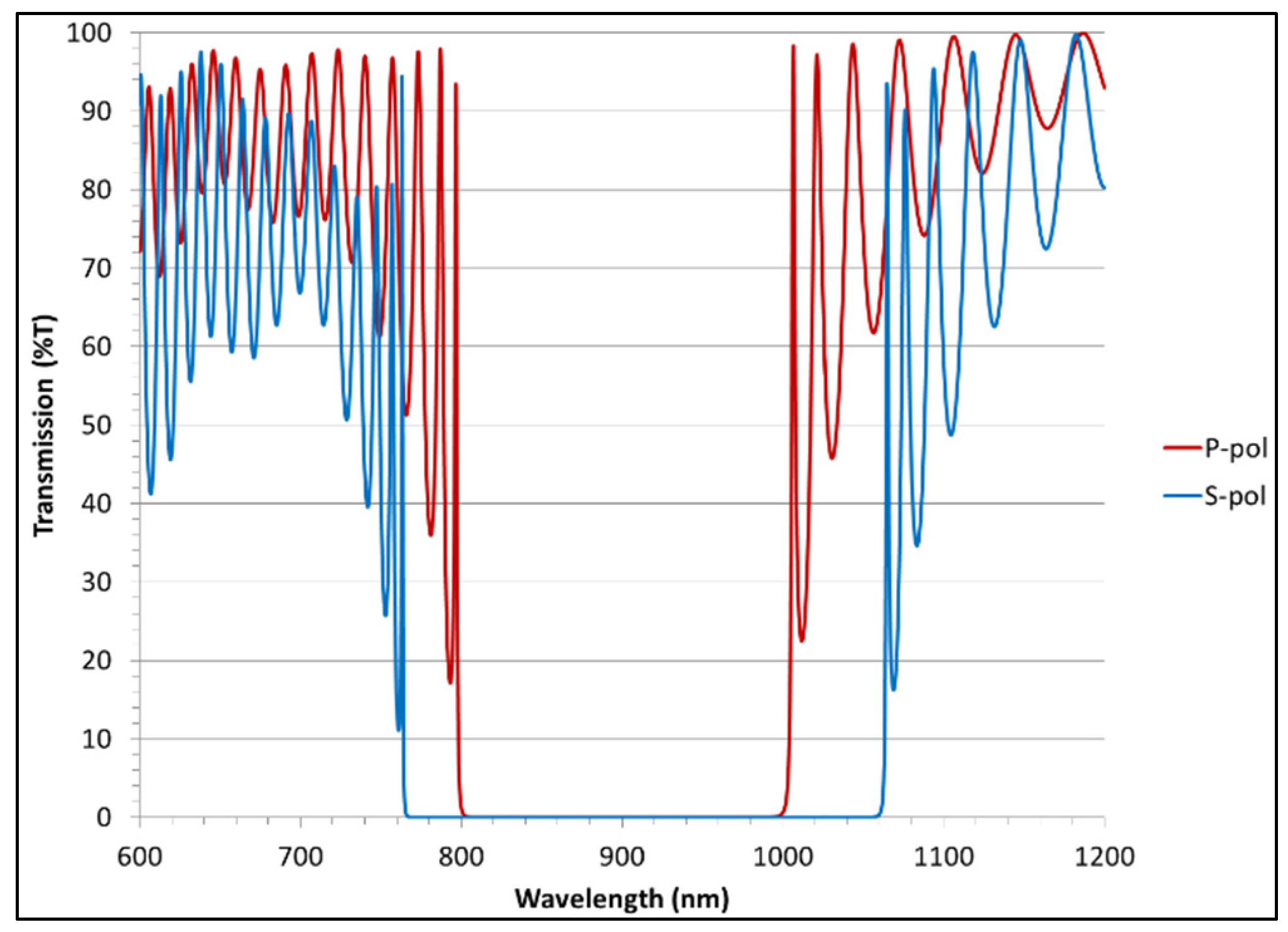
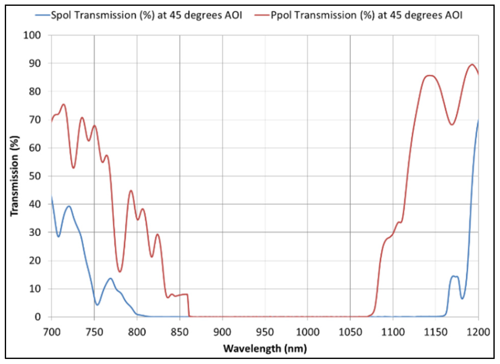
5.1. Transmission Spectra for the BBHR Design

The Ppol and Spol transmission spectra at 45° AOI for our BBHR coating design are shown in Figure 3 for the 600 nm to 1200 nm spectral range. The transmission spectra are well-behaved, and the bandwidth for Ppol reflectivity exceeding 99.5% is 198 nm (from 801.22 to 999.24 nm). This is very close to the 200 nm BBHR bandwidth goal of Table 1. The bandwidth for Spol reflectivity exceeding 99.5% is 294 nm (from 765.64 to 1059.94 nm), which is considerably larger than that for Ppol reflectivity. This is consistent with what we expect for a coating that is close to being like a quarter-wave HR coating [13] in its performance.

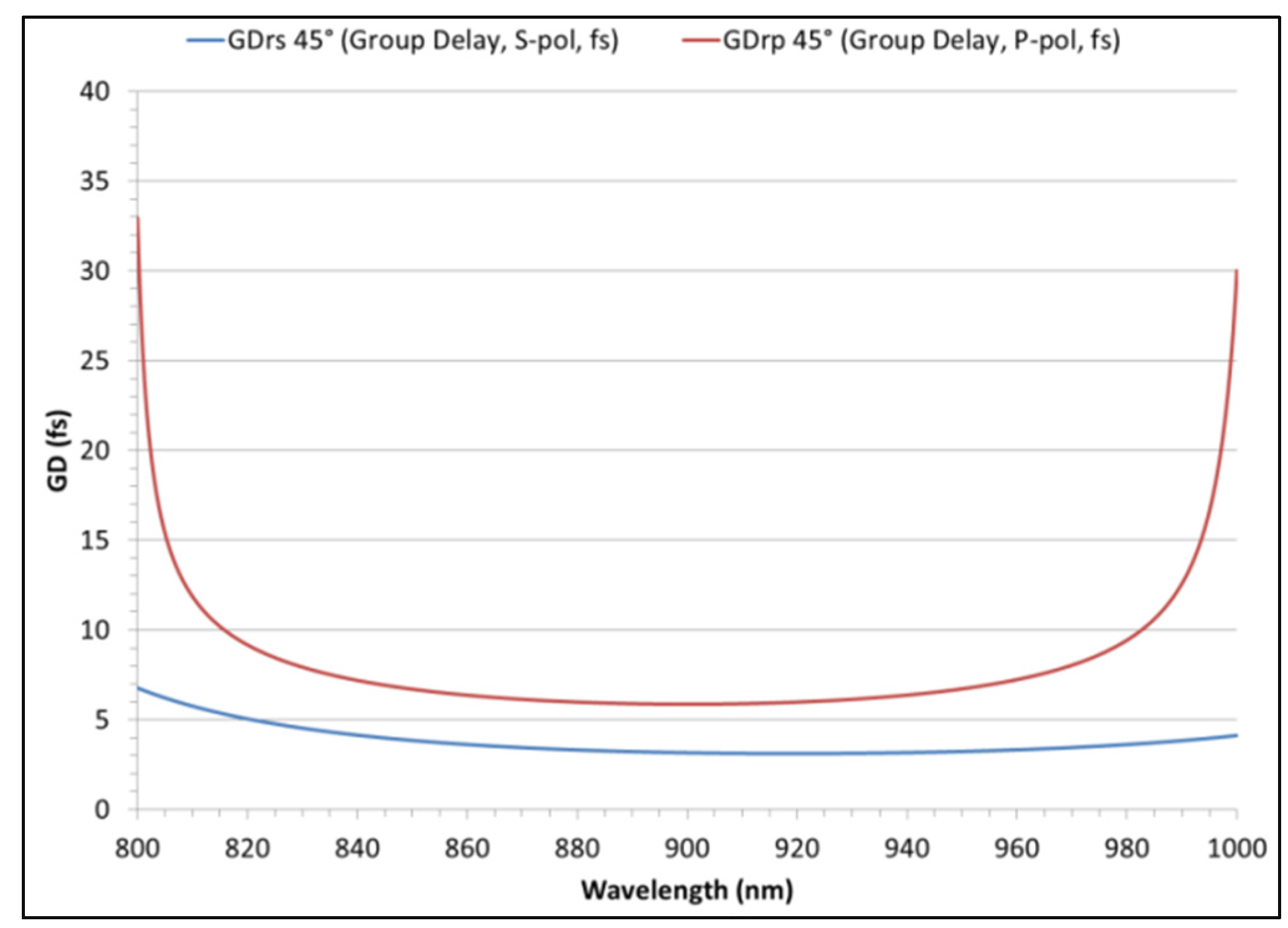
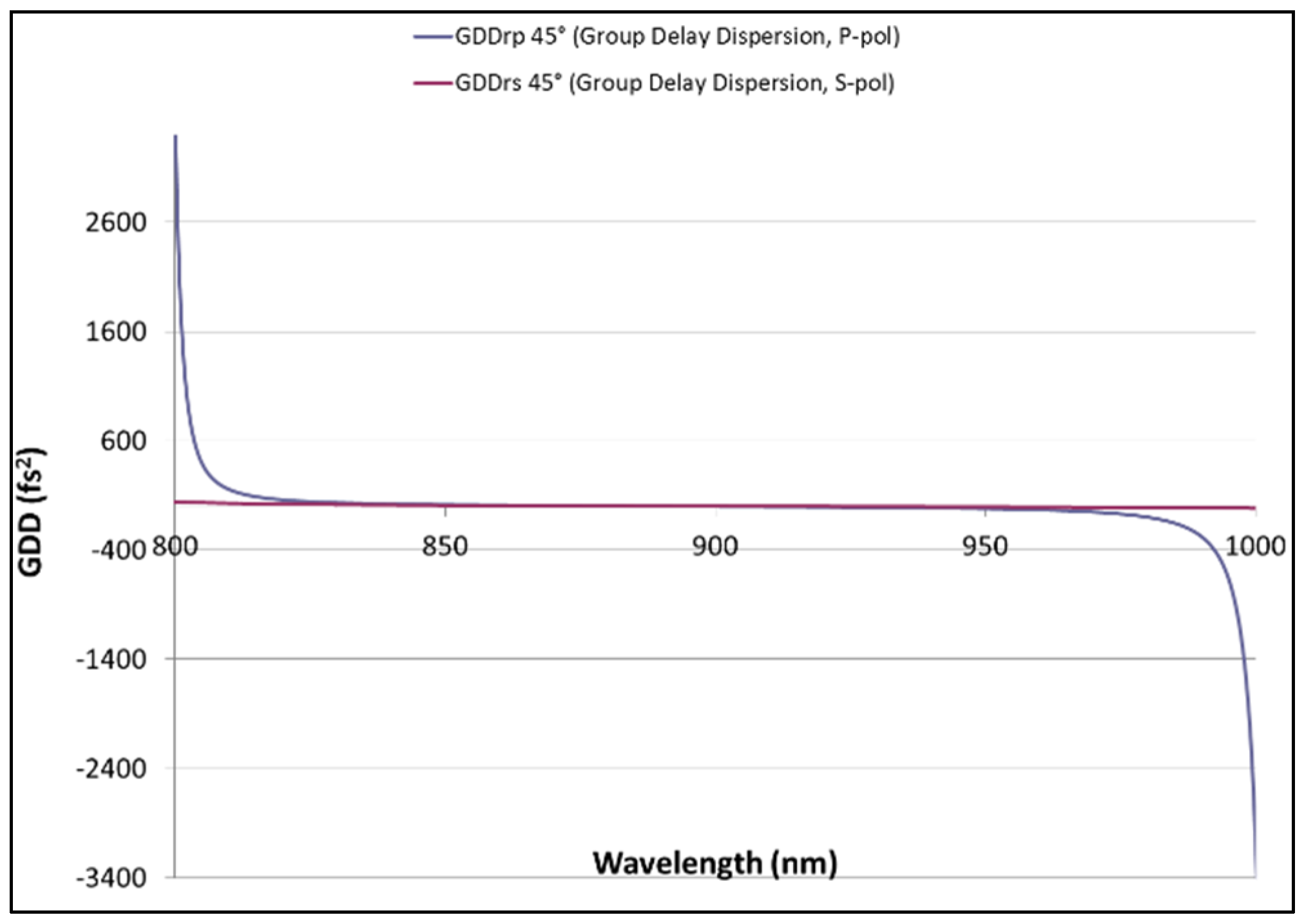
5.2. GD and GDD Behaviors for the BBHR Design

Figure 4 shows Ppol and Spol GDs based on our BBHR coating design over the operational bandwidth for reflection at 45° AOI. The GD variation with wavelength is very smooth overall and fairly flat, with the Ppol GD between ~6 and ~10 fs in the interval of 816–982 nm and the Spol GD between ~3 and ~7 fs over the entire operational band. Beyond the 816–982 nm spectral range for Ppol, the GD rises smoothly to ~35 fs at 800 nm, and to ~30 fs at 1000 nm. The corresponding GDDs are shown by Figure 5 and, on an expanded scale, by Figure 6. The GDDs are definitely not constant with wavelength but are within ±20 fs2 from 843 to 949 nm for Ppol, and from 822 to 1000 nm and beyond for Spol, and are within ±50 fs2 from 823 to 969 nm for Ppol, and over the entire operational bandwidth and beyond for Spol. GDD rises smoothly in magnitude as wavelengths approach the low and high wavelength extremes of the operational band. For Ppol, GDD rises smoothly from 50 fs2 at 823 nm to ~3500 fs2 at 800 nm, and drops smoothly from −50 fs2 at 970 nm to −3500 fs2 at 1000 nm. Because of this smooth variation with wavelength of GD and GDD, the prospect of being able to compensate for large GDD (such as >20 fs2 or >50 fs2) where it occurs over the operational band is promising.

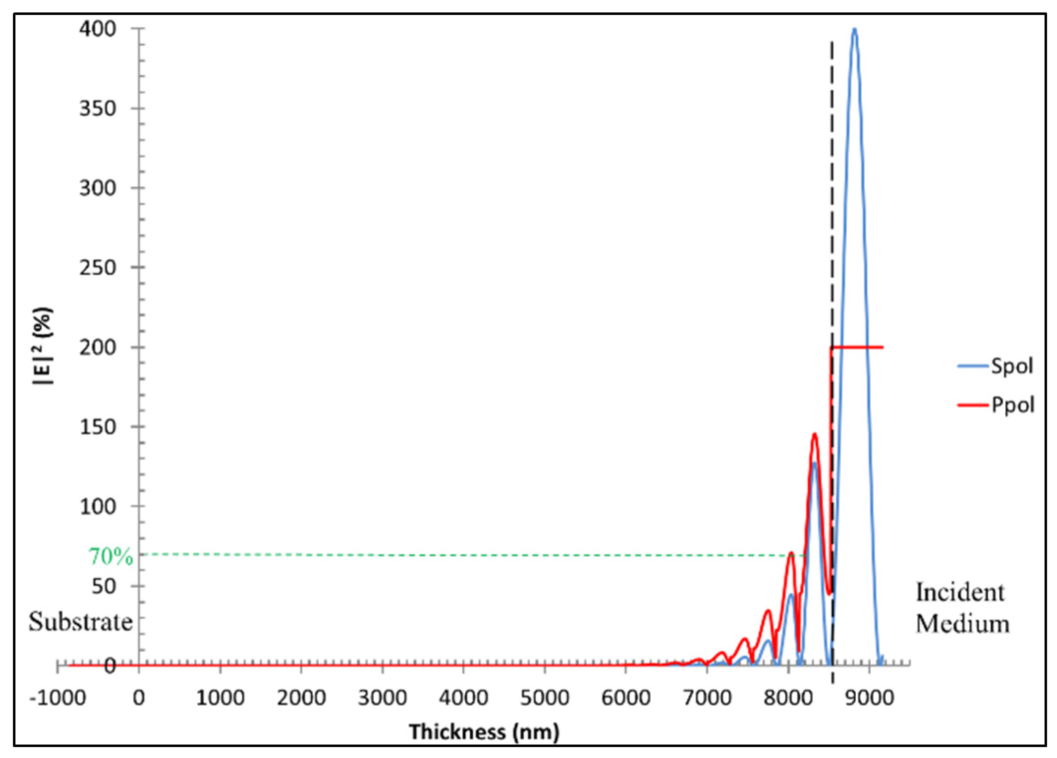
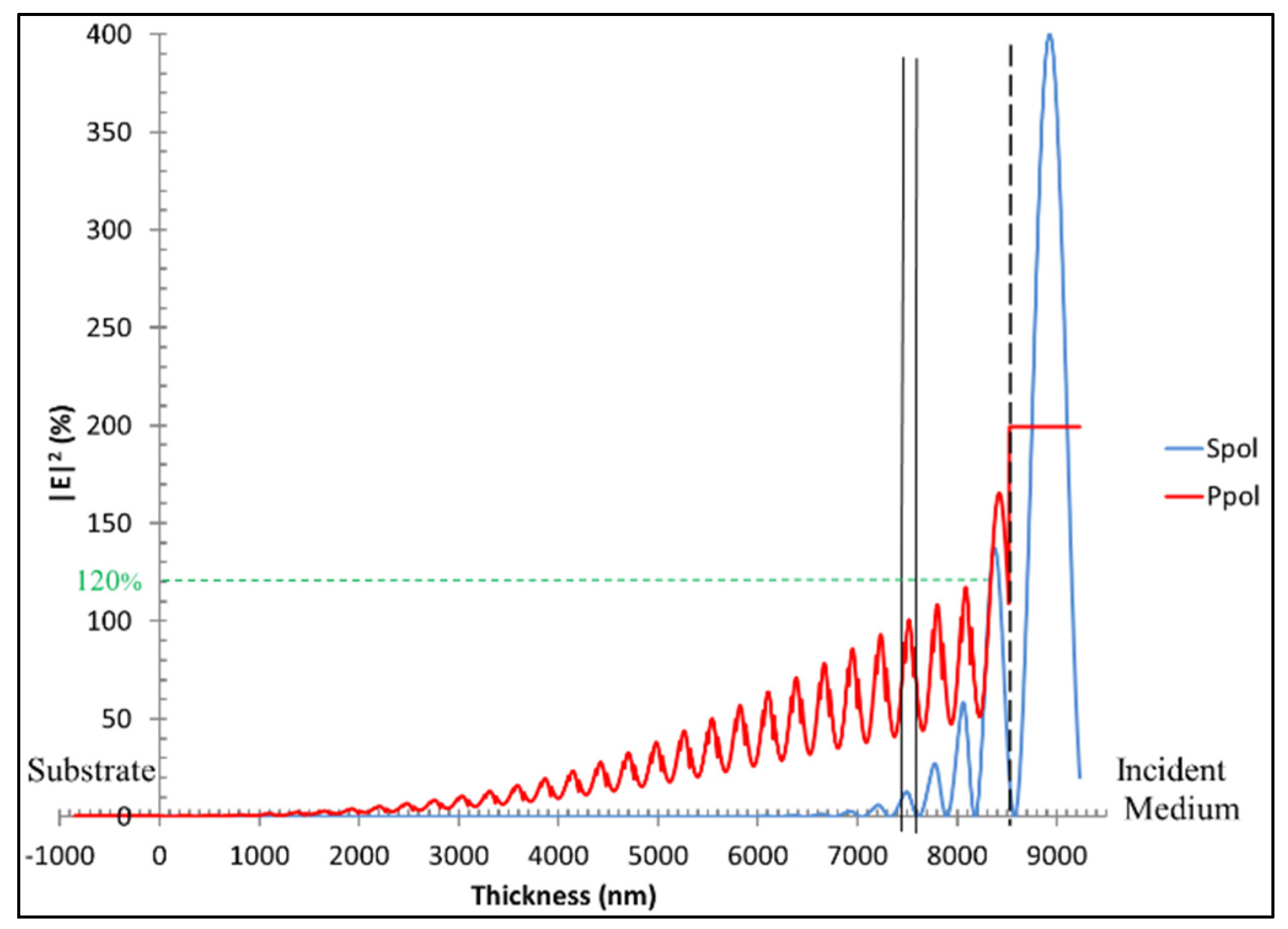
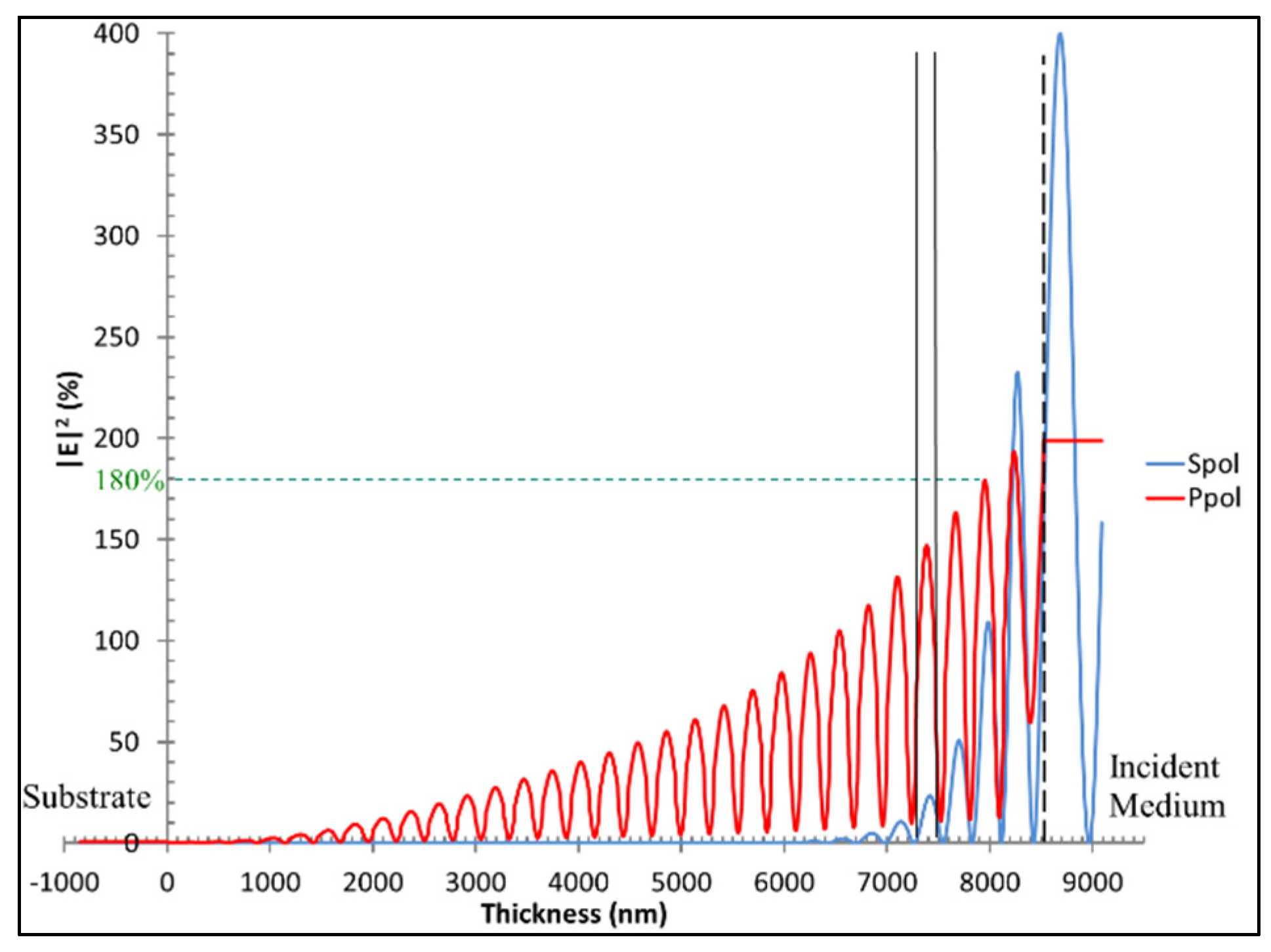
5.3. E-Field Intensities for the BBHR Design and Implications for LIDTs

The E-field intensity peaks for both Spol and Ppol are highest in the outer thick SiO2 layer of the BBHR coating design for all operational wavelengths and rapidly quench within the outer coating layers to very low values, as shown in Figure 7 for the case of 900 nm. This quenching leads to intensity peaks, like those of Figure 7, that reach < 20% of the incident intensity within the outer ~12 layers over the entire operational band for Spol and over most of the operational band, from ~810 to ~990 nm, for Ppol. For Spol (Ppol), the maximum intensity peaks in the outer thick, half-wave SiO2 layer are less than about 210% (180%) and as low as about 120% (140%) of the incident intensity from ~810 to 1000 nm. The Spol and Ppol E-field intensity peaks for the ~810–1000 nm wavelength range are < 70% of incident intensity for all coating layers after the half-wave outer layer, similar to those shown in Figure 7 for 900 nm.
From 810 to 800 nm, the highest peak intensities in the outer thick SiO2 layer increase for both Spol and Ppol and, for these wavelengths as well as for 990–1000 nm wavelengths, the quenching of the intensity peaks becomes much more gradual for Ppol. As shown in Figure 8 for 1000 nm wavelength light, the Ppol intensity peaks quench down to < 20% of the incident intensity gradually, over ~30 outermost layers, and occur in the middle of TiO2 layers, one of which is indicated by the two vertical, solid black lines in the figure. While these intensity peaks in TiO2 layers are not favorable to high LIDT because of the lower bandgap of TiO2, they are of moderate strength, remaining < 120% of incident intensity after the outer, ~half-wave layer (see Figure 8). These moderate peak intensities lessen the negative impact on LIDT.
For 800 nm wavelength light, Figure 9 shows that the outer layer peak intensity is ~190% of the incident intensity for Ppol and ~230% of the incident intensity for Spol, and the intensity peaks quench down to < 20% of the incident intensity over ~39 outermost layers for Ppol. These intensity peaks are stronger, being < 180% of incident intensity after the outer, ~half-wave layer, compared to those for wavelengths near 1000 nm (Figure 8). The LIDT impact of this higher peak intensity behavior for both Spol and Ppol within the coating at 800–810 nm is, however, mitigated by a shift at these wavelengths of the peaks so that they occur in the middle of the higher bandgap SiO2 layers, one of which is indicated by the two vertical solid black lines in Figure 9. These E-field behaviors, with the higher intensity peaks in the higher bandgap SiO2 layers, and the moderate intensity peaks in the lower bandgap TiO2 layers, are favorable overall to high LIDTs.

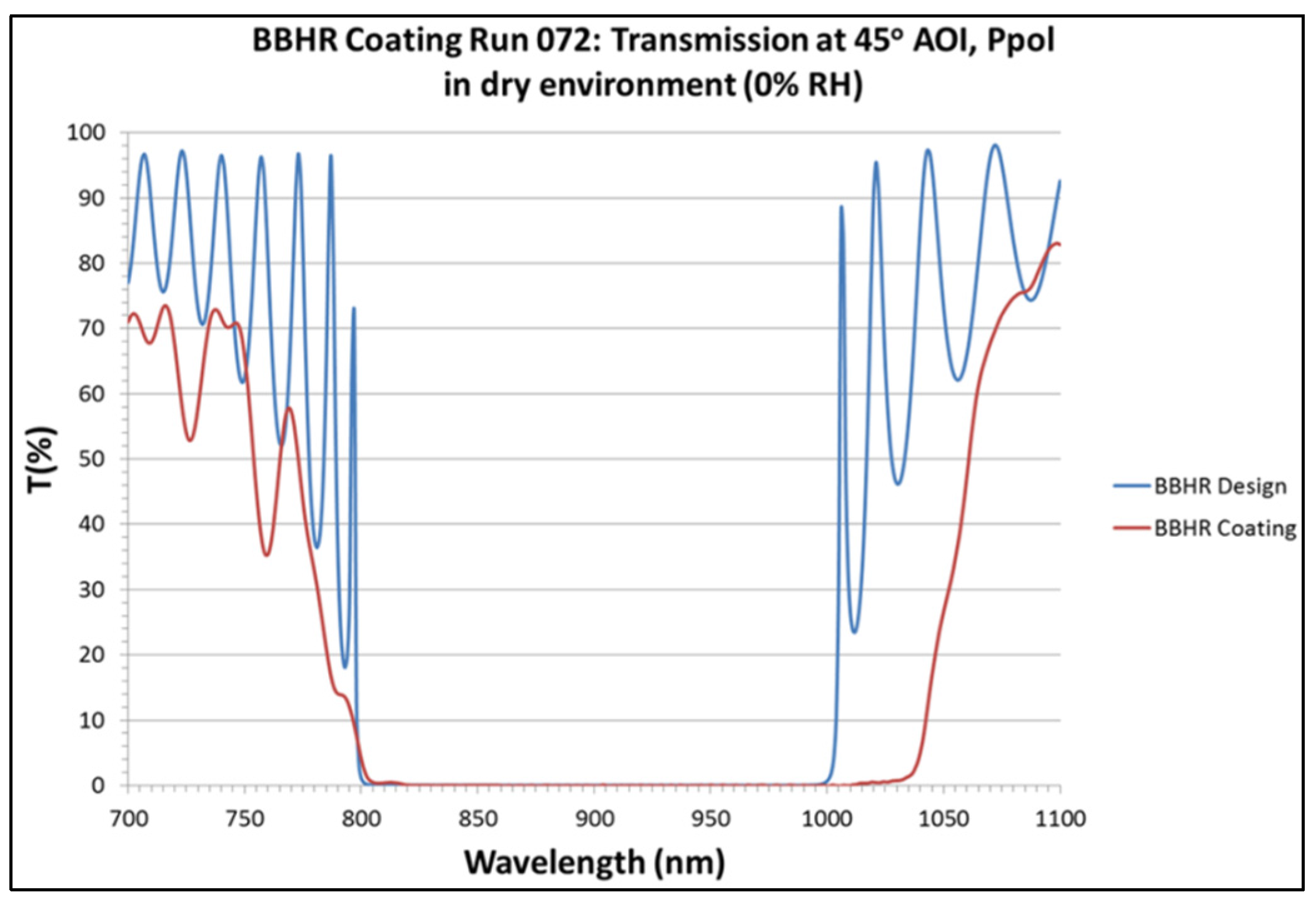
6. Initial Test Coating Run Based on the BBHR Design

The initial test coating run for the BBHR design produced encouraging results. Figure 10 shows the Spol and Ppol transmission spectra of this test coating as measured on a Lambda 950 Spectrophotometer (PerkinElmer, Waltham, MA, USA) under dry (0% relative humidity) conditions immediately after the run. The BBHR center wavelength for this coating is shifted to 967 nm, which is 67 nm higher than the design goal, but the Ppol HR bandwidth for R > 99.5% is 213 nm, exceeding the design goal by 13 nm. This overall spectral shift is an artifact of the deposition calibrations and can easily be compensated by a re-calibration of the deposition process.
Figure 11 shows measured results of Spol and Ppol GDD for the initial BBHR test coating. These measurements were made by J. Oliver and C. Smith at University of Rochester using a Chromatis test instrument [22] one month after the coating run. They show a smoothly varying GDD with |GDD| < 100 fs2 over the HR band, which appears to have shifted to even higher wavelength compared to the spectra of Figure 10. This is not surprising since our own spectral measurements taken over time and in various conditions of relative humidity indicate that aging effects and the ~40% relative humidity of the ambient environment of the GDD measurements could have caused ~4% shift of the HR band to longer wavelengths.

7. Subsequent Coating Runs Based on the BBHR Design

Re-calibration of the deposition process did, indeed, lead to two coating runs, Runs 071 and 072, which produced coatings based on the BBHR design that exhibit transmission spectra for 45° AOI, Ppol in excellent agreement with the design. Between the initial test run and Runs 071 and 072, we conducted a total of 6 coating runs based on the BBHR design. These 6 coating runs differed only in layer thickness monitoring calibration, and the transmission spectra of the resulting coatings were all similar in BBHR bandwidth and shape. This indicates that the BBHR coating design is insensitive to common run-to-run layer thickness variations, at least in regard to its BBHR properties.
We have reported on the coatings of Runs 071 and 072 elsewhere [15]. Here, for the sake of completeness, we summarize important results. Each coating run’s calibration allowed for a specific amount of spectral drift of the BBHR band of the coating resulting from effects due to its aging and absorption of moisture in the case of humid-use environments. The coating of Run 072 was specific to the BBHR performance in dry, 0% relative humidity (RH), or vacuum environments, and the coating of Run 071was specific to the BBHR performance in a humid, ~50% RH environment. Figure 12 shows one of the results, namely, the transmission spectrum for the BBHR coating of Run 072 at 45° AOI, Ppol measured under 0% RH conditions as compared to the corresponding design transmission spectrum of Figure 3. This result is important because of the good agreement between the two spectra, and the HR bandwidth of the Run 072 coating that exceeds the 200 nm design goal (Table 1).
The LIDT tests of our earlier report [15] took place under dry conditions and were at 1064 nm with 800 ps and 8 ps pulses, and at 1053 nm with 675 fs pulses. These tests probed the LIDT of the coatings within narrow spectral sub-bands both near the long wavelength edges of the HR bands as well as within their central spectral zones. This was accomplished by adjustment of AOI to appropriately shift the coatings’ transmission spectra in wavelength so that the 1064 nm or 1053 nm LIDT wavelengths were either within the central spectral zones or near the band edges of the BBHR bands. The tests at 1053 nm were performed by L. Lamaignere and M. Sozet of CEA-CESTA in France on the BBHR coating of Run 072 using the laser test facility called DERIC [23] with 675 fs pulses in 1-on-1 and 10-on-1 formats based on ISO 11254-1 [21] and ISO 11254-2 [24] protocols, respectively. For 1-on-1 and 10-on-1 tests, these LIDTs are 1.34 J/cm2 and 1.15 J/cm2, respectively, in the central part of the BBHR band (with 0° AOI), and are 1.15 J/cm2 and 0.8 J/cm2, respectively, near the edge of the BBHR band (with 40° AOI, Ppol).
The LIDT tests at 1064 nm were performed by Spica Technologies, Inc. [25] on the BBHR coating of Run 071 using the NIF-MEL protocol [20] with 800 ps and 8 ps pulses. For the tests with 800 ps pulses, the LIDT is 11 J/cm2 in the central part of the BBHR band (with 0° AOI) and 9 J/cm2 near the BBHR band edge (with 19° AOI, Ppol). For the tests with 8 ps pulses, the LIDT is 1.25 J/cm2 in the central part of the BBHR band (with 0° AOI) and 1.5 J/cm2 near the BBHR band edge (with 19° AOI, Ppol). These LIDT results provide useful comparisons of laser damage behaviors for different spectral zones of the BBHR band, and confirm LIDT pulse scaling trends from ns to 675 fs pulse regimes. They do not, however, allow accurate estimations of LIDTs for the fs pulses with 900 nm center wavelength that the BBHR coating needs to be able to reflect with adequate resistance to laser damage according to the design goals (Table 1). We hope to have such fs LIDT test results on coatings based on our BBHR design in the near future.

8. Summary and Conclusions

We have developed a coating design for 45° AOI, Ppol BBHR with 200 nm bandwidth centered at 900 nm, and suitable for reflection of fs pulses without degradation of their temporal profiles. The BBHR design exhibits HR and GDD performances that behave smoothly and deviate only slightly from design goals, and is favorable to high LIDT. Furthermore, because of their smooth behavior, the slight deviations from GDD design goals can very likely be compensated. We have given a detailed account of our BBHR design considerations, which are guided by the properties of basic quarter-wave HR coatings. The coating is based on TiO2 and SiO2 for the H index and L index layers, respectively, and we have explained this choice of layers in the context of their production in Sandia’s large optics coater by means of e-beam evaporation with ion-assisted deposition. Our considerations led us to a reverse chirped set of H and L index layer thicknesses as the starting point for using optimization algorithms of the OptiLayer Thin Film Software to obtain the BBHR design. An analysis of the optical E-field behaviors within the coating layers for 45° AOI, Ppol reflection across the HR spectrum indicates that our BBHR design is favorable to high LIDTs.
Measured HR and GDD of the coating from the initial test coating run based on the BBHR design are promising. This initial test run together with subsequent coating runs have shown that the BBHR design is stable against run-to-run layer thickness variations, and have produced, in Runs 071 and 072, coatings whose HR bands provide an excellent match to the design goal. We have summarized transmission and LIDT results for these two coatings based on our earlier, more complete report [15]. Table 5 consolidates the results of LIDT tests we have so far for all of our TiO2/SiO2 BBHR coatings, showing the trends with test laser pulse duration from the ns to sub-ps regimes. These LIDT results, at 1064 nm with 800 ps and 8 ps pulses and at 1053 nm with 675 fs pulses, show laser damage behaviors of the Run 071 and Run 072 BBHR coatings in the central spectral zones compared to near the edges of their BBHR bands. We hope to have, in the near future, results of LIDT tests of our coatings with the fs pulses and 900 nm center wavelength for which we developed the BBHR design of this paper. Our experience in producing multilayer dielectric optical coatings on meter-class optics [6,7] gives us confidence toward meeting our eventual goal of uniformly depositing the BBHR coatings of Runs 071 and 072 on large dimension mirror substrates.

Acknowledgments

Sandia National Laboratories is a multi-program laboratory managed and operated by Sandia Corporation, a wholly owned subsidiary of Lockheed Martin Corporation, for the U.S. Department of Energy’s National Nuclear Security Administration under contract DE-AC04-94AL85000. This paper is based on invited presentations by one of us (JCB) at the 3rd Frontiers of Optical Coatings International Conference on Optical Thin Film and Coating Technology held at Tongji University in Shanghai, China 20–24 October 2014, and at the Pacific Rim Laser Damage 2015: Optical Materials for High-Power Lasers Conference held in Jiading, Shanghai, China 17–20 May 2015. We thank James Oliver and Christopher Smith of University of Rochester in the United States for providing the GDD measurements, and Laurent Lamaignere and Martin Sozet of CEA/CESTA in France for providing the LIDT measurements with 675 fs pulses at 1053 nm.

Author Contributions

John C. Bellum is the technical project leader and developed the BBHR coating design. Ella S. Field developed the deposition processes for the TiO2 layers. Trevor B. Winstone conceived this research endeavor and provided technical oversight. Damon E. Kletecka produced the BBHR coatings in the Sandia large optics coater. The work conducted at Sandia was a team effort.

Conflicts of Interest

The authors declare no conflict of interest.

References

  1. Schwarz, J.; Rambo, P.; Geissel, M.; Edens, A.; Smith, I.; Brambrink, E.; Kimmel, M.; Atherton, B. Activation of the Z-petawatt laser at sandia national laboratories. In Proceedings of The 5th International Conference on Inertial Fusion Sciences and Applications (IFSA2007), Kobe, Japan, 9–14 September 2007; pp. 1–4.
  2. Rambo, P.K.; Smith, I.C.; Porter, J.L., Jr.; Hurst, M.J.; Speas, C.S.; Adams, R.G.; Garcia, A.J.; Dawson, E.; Thurston, B.D.; Wakefield, C.; et al. Z-Beamlet: A multi-kilojoule, terawatt-class laser system. Appl Opt. 2005, 44, 2421–2430. [Google Scholar] [CrossRef] [PubMed]
  3. Z-Backlighter Laser Facility, Sandia National Laboratories Homepage. Available online: http://www.z-beamlet.sandia.gov (accessed on 7 March 2016).
  4. Matzen, M.K.; Atherton, B.W.; Cuneo, M.E.; Donovan, G.L.; Hall, C.A.; Herrmann, M.; Kiefer, M.L.; Leeper, R.J.; Leifeste, G.T.; Long, F.W.; et al. The refurbished Z Facility: Capabilities and recent experiments. Acta Phys. Polonica A 2009, 115, 956–958. [Google Scholar] [CrossRef]
  5. Z-Accelerator, Sandia National Laboratories Homepage. Available online: http://www.sandia.gov/z-machine/ (accessed on 7 March 2016).
  6. Bellum, J.; Kletecka, D.; Rambo, P.; Smith, I.; Kimmel, M.; Schwarz, J.; Geissel, M.; Copeland, G.; Atherton, B.; Smith, D.; et al. Meeting thin film design and production challenges for laser damage resistant optical coatings at the Sandia Large Optics Coating Operation. In Proceedings of the 41st Annual Laser Damage Symposium, Laser-Induced Damage in Optical Materials: 2009, Boulder, CO, USA, 21–23 September 2009.
  7. Bellum, J.; Rambo, P.; Schwarz, J.; Smith, I.; Kimmel, M.; Kletecka, D.; Atherton, B. Production of optical coatings resistant to damage by petawatt class laser pulses. In Lasers—Applications in Science and Industry; Jakubczak, K., Ed.; InTech Open Access Publisher: Rijeka, Croatia, 2011; pp. 23–52. [Google Scholar]
  8. Baumeister, P.W.; Stone, J.M. Broad-band multilayer film for fabry-perot interferometers. J. Opt. Soc. Am. 1956, 46, 228–229. [Google Scholar] [CrossRef]
  9. Heavens, O.S.; Liddell, H.M. Staggered broad-band reflecting multilayers. Appl. Opt. 1966, 5, 373–376. [Google Scholar] [CrossRef] [PubMed]
  10. Pervak, V. Recent development and new ideas in the field of dispersive multilayer optics. Appl. Opt. 2011, 50, C55–C61. [Google Scholar] [CrossRef] [PubMed]
  11. Szipöcs, R.; Kárpát, F. Chirped multilayer coatings for broadband dispersion control in femtosecond lasers. Opt. Lett. 1994, 19, 201–203. [Google Scholar]
  12. Oliver, J.; Bromage, J.; Smith, C.; Sadowski, D.; Dorrer, C.; Rigatti, A.L. Plasma-ion-assisted coatings for 15 femtosecond laser systems. Appl. Opt. 2014, 53, A221–A228. [Google Scholar] [CrossRef] [PubMed]
  13. Macleod, H.A. Thin-Film Optical Filters; Institute of Physics: Bristol and Philadelphia, PA, UK and USA, 2002. [Google Scholar]
  14. Tikhonravov, A.V.; Trubetskov, M.K. OptiLayer Thin Film Software. Available online: http://www.optilayer.com (accessed on 7 March 2016).
  15. Bellum, J.; Winstone, T.; Lamaignere, L.; Sozet, M.; Kimmel, M.; Rambo, P.; Field, E.; Kletecka, D. Analysis of laser damage tests on a coating for broad bandwidth high reflection of femtosecond pulses. In Proceedings of Pacific Rim Laser Damage 2015: Optical Materials for High-Power Lasers, Jiading, Shanghai, China, 17–20 May 2015.
  16. Wollenhaupt, M.; Assion, A.; Baumert, T. Femtosecond laser pulses: linear properties, manipulation, generation and measurement. In Springer Handbook of Lasers and Optics; Träger, F., Ed.; Springer: New York, NY, USA, 2007; pp. 937–983. [Google Scholar]
  17. Born, M.; Wolf, E. Principles of Optics; Pergamon Press: New York, NY, USA, 1980; Section 7.5.8. [Google Scholar]
  18. Field, E.S.; Bellum, J.C.; Kletecka, D.E. Laser damage comparisons of broad-bandwidth, high-reflection optical coatings containing TiO2, Nb2O5, or Ta2O5 high index layers. In Proceedings of the 45th Annual Laser Damage Symposium, Laser-Induced Damage in Optical Materials: 2013, Boulder, Colorado, USA, 22–25 September 2013.
  19. Bellum, J.; Field, E.; Kletecka, D.; Long, F. Reactive ion-assisted deposition of e-beam evaporated titanium for high refractive index TiO2 layers and laser damage resistant, broad bandwidth, high-reflection coatings. Appl. Opt. 2014, 53, A205–A211. [Google Scholar] [CrossRef] [PubMed]
  20. NIF Technical Report MEL01–013–0D: Small Optics Laser Damage Test Procedure; Lawrence Livermore National Laboratory: Livermore, CA, USA, 2005.
  21. ISO Standard 11254–1: Lasers and Laser-Related Equipment—Determination of Laser-Damage Threshold of Optical Surfaces—Part 1: 1-on-1 Test; International Organization for Standardization: Geneva, Switzerland, 2000.
  22. Chromatis Test Instrument, Kapteyn-Murnane Laboratories Homepage. Available online: http: //www.KMLabs.com/content/chromatis (accessed on 7 March 2016).
  23. Sozet, M.; Néauport, J.; Lavastre, E.; Roquin, N.; Gallais, L.; Lamaignère, L. Laser damage density measurement of optical components in the sub-picosecond regime. Opt. Lett. 2015, 40, 2091–2094. [Google Scholar] [CrossRef] [PubMed]
  24. ISO Standard 11254–2: Lasers and laser-related equipment—Determination of Laser-induced Damage Threshold of Optical Surfaces —Part 2: S-on-1 Test; International Organization for Standardization: Geneva, Switzerland, 2001.
  25. Spica Technologies, Inc. Homepage. Available online: http://www.spicatech.com (accessed on 7 March 2016).
Figure 1. (a) Schematic depicting the dispersive variation with wavelength of the index of refraction and the effective for S polarization (Spol) and P polarization (Ppol) indices for non-normal angle of incidence (AOI) for the H and L index layers of a BBHR coating. See the text for explanation of the labels; (b) Schematic depicting two transmission spectra for a BBHR coating, one of more and the other of less layers, as indicated. λ0 is the center wavelength of the spectra. The bandwidth label refers to the BBHR counterpart to the bandwidth, ΔλFWHM, of quarter-wave HR coatings, for which ΔλFWHM0 = (2Δg)/[1 − (Δg)2] where Δg depends on polarization and, for Spol(Ppol), is given by (2/π)sin−1[(ρeff,Spol(Ppol) − 1)/(ρeff,Spol(Ppol) + 1)] [13].
Coatings 06 00011 g001
Figure 2. Index of refraction and absorption as functions of wavelength for the SiO2 and TiO2 coating layers. The inserts to the right show the index data on expanded scales. Absorption is k where 4πk/λ is the optical absorption coefficient.
Coatings 06 00011 g002
Figure 3. Ppol and Spol transmission spectra at 45° AOI for the BBHR coating design.
Coatings 06 00011 g003
Figure 4. Group delay (GD) on reflection as a function of wavelength for 45° AOI, Spol and Ppol, for the BBHR coating design.
Coatings 06 00011 g004
Figure 5. Group delay dispersion (GDD) on reflection as a function of wavelength for 45° AOI, Spol and Ppol, for the BBHR coating design.
Coatings 06 00011 g005
Figure 6. GDD on reflection as a function of wavelength for 45° AOI, Spol and Ppol, for the BBHR coating design, shown on an expanded GDD scale.
Coatings 06 00011 g006
Figure 7. Optical E-field intensities (as % of incident intensity) within the coating for 900 nm wavelength light at 45° AOI, Spol and Ppol, for the BBHR coating design. The vertical dashed line indicates the boundary of the coating with the incident medium. This figure appeared as the top left-hand graph in Figure 6 and Figure 8 of our earlier report [15].
Coatings 06 00011 g007
Figure 8. Optical E-field intensities (as % of incident intensity) within the coating for 1000 nm wavelength light at 45° AOI, Spol and Ppol, for the BBHR coating design. The vertical dashed line indicates the boundary of the coating with the incident medium. The two vertical solid lines indicate a TiO2 coating layer. This figure appeared as the bottom left-hand graph in Figure 6 and Figure 8 of our earlier report [15].
Coatings 06 00011 g008
Figure 9. Optical E-field intensities (as % of incident intensity) within the coating for 800 nm wavelength light at 45° AOI, Spol and Ppol, for the BBHR coating design. The vertical dashed line indicates the boundary of the coating with the incident medium. The two vertical solid lines indicate a SiO2 coating layer.
Coatings 06 00011 g009
Figure 10. Measured Transmission spectra at 45° AOI for Ppol and Spol for the initial BBHR test coating.
Coatings 06 00011 g010
Figure 11. Measured GDD as a function of wavelength for reflection at 45° AOI, Ppol and Spol, for the initial BBHR test coating.
Coatings 06 00011 g011
Figure 12. Transmission spectrum as measured under dry (0% RH) conditions at 45° AOI, Ppol for the BBHR coating of Run 072, with the measured spectrum shown compared to the coating’s design transmission spectrum. This figure appears as Figure 2 of our earlier report [15].
Coatings 06 00011 g012
Table 1. Broad bandwidth high reflection (BBHR) coating design goals.
ReflectivityOperational BandwidthLIDTGDD
>99.5% for 45° AOI, Ppol800–1000 nm>800 mJ/cm2 for fs-class pulses<20 fs2 over the operational bandwidth
Table 2. Frequency bandwidth, Δυ, and wavelength bandwidth, Δλ, for pulses of 900 nm center wavelength and durations, Δτ, as indicated.
ΔτΔυ (109 Hz)Δλ (nm)
1 ns10.0027
100 ps100.027
10 ps1000.27
1 ps10002.7
100 fs1000027
10 fs100000270
Table 3. Examples, for TiO2 (H index) and SiO2 (L index) layers, of variations in layer indices, propagation angle, path, and optical path at 800 nm and 1000 nm band edges of a 200 nm BBHR band centered at 900 nm for 45° AOI, Ppol, where tH and tL are the respective layer thicknesses. Section 4.1 below describes the TiO2 and SiO2 layers.
Layer PropertyH Index LayersL Index Layers
800 nm1000 nm800 nm1000 nm
layer index2.2958842.2695801.4579661.455900
propagation angle in layer17.938°18.153°29.0122°29.0573°
path in layer1.0511 × tH1.0524 × tH1.1435 × tL1.1440 × tL
optical path in layer2.4132 × tH2.3885 × tH1.6672 × tL1.66555 × tL
Table 4. Cauchy parameters for the TiO2 and SiO2 coating layers.
Thin Film LayerA0A1A2
TiO22.2241010.0446578.2192065 × 10−4
SiO21.4522280.0036721983.935249 × 10−8
Table 5. LIDT test results for TiO2/SiO2 BBHR coatings.
Coating & BBHR Band (for R > 99.5%)Test Center WavelengthTest Pulse DurationTest AOITest PolarizationTest ProtocolLIDT (J/cm2)LIDT Reference
Coating 1
940–1171 nm
1064 nm3.5 ns45°PNIF-MEL [20]28[18]
Coating 1
940–1171 nm
1064 nm10 ns45°PISO 11254-1 [21] (1-on-1)17.5[18]
Coating 2
971–1203 nm
1064 nm3.5 ns45°PNIF-MEL [20]19[19]
Coating 2
971–1203 nm
1064 nm10 ns45°PISO 11254-1 [21] (1-on-1)12.7[19]
Coating, Run 071
819–1108 nm
1064 nm800 psNIF-MEL [20]11[15]
Coating, Run 071
819–1108 nm
1064 nm8 psNIF-MEL [20]1.25[15]
Coating, Run 071
808–1097 nm
1064 nm800 ps19°PNIF-MEL [20]9[15]
Coating, Run 071
808–1097 nm
1064 nm8 ps19°PNIF-MEL [20]1.5[15]
Coating, Run 072
866–1169 nm
1053 nm675 fsISO 11254-1 [21] (1-on-1)1.34[15]
Coating, Run 072
866–1169 nm
1053 nm675 fsISO 11254-2 [24] (10-on-1)1.15[15]
Coating, Run 072
818–1060 nm
1053 nm675 fs40°PISO 11254-1 [21] (1-on-1)1.15[15]
Coating, Run 072
818–1060 nm
1053 nm675 fs40°PISO 11254-2 [24] (10-on-1)0.8[15]

