3. Results and Discussion
As shown in the SEM picture reported in
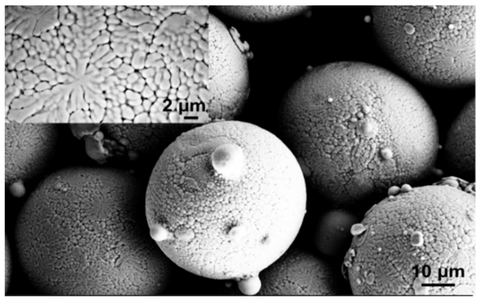
Figure 1, the powder feedstock is composed of spherical particle agglomerates. The inset in the left corner of the same micrograph shows the detailed surface morphology of an agglomerate, characterized by grains with size lower and higher than 1 μm and with spherical, quasi-spherical and elongated shape. Some dendritic structures can be also observed. The grey contrast could be associated to fluctuations in Al content. The particle size distribution measured by SEM observations was in the range between 45 and 65 μm, while the average particle size was 54 ± 5 μm.
Figure 1.
SEM spherical morphology of NiCoCrAlYRe particle agglomerates. Grains with submicrometer size can be observed on the surface.
Figure 1.
SEM spherical morphology of NiCoCrAlYRe particle agglomerates. Grains with submicrometer size can be observed on the surface.
In turn
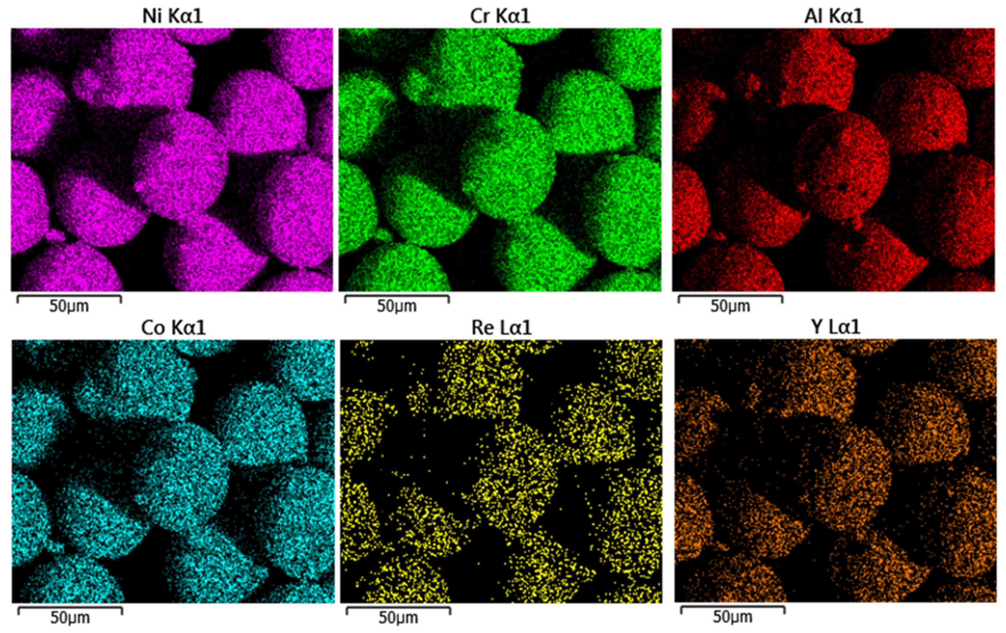
Figure 2 shows the EDS map of powder particles, suggesting the presence of significant amount of Re and Y. The measured chemical composition (wt%) of the powder feedstock can be summarized as 52Ni 10Co 24Cr 10Al 1Y 3Re.
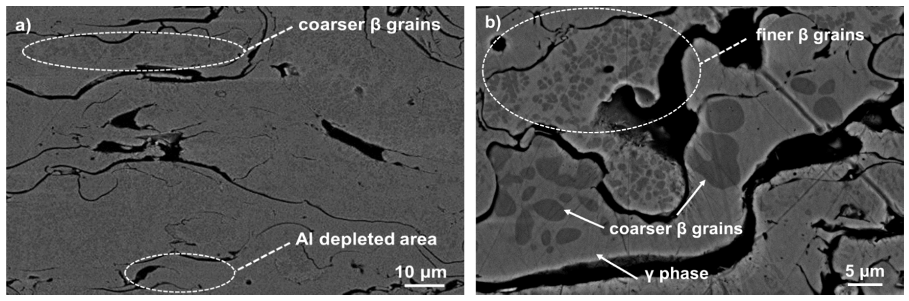
Figure 3a,b shows the cross sectional microstructure of plasma sprayed NiCoCrAlYRe coating at different magnification. The coating exhibits a lamellar microstructure composed of overlapped splats, originated by deformation and quenching of molten droplets at the substrate surface during deposition process. Some pores and splat boundaries can be observed. The former are related to filling defects produced by gas entrapped in the molten droplets during coating build-up, whereas the splat boundaries derived from weak bonding between the overlapped splats, depending on the temperature distribution along the same ones during cooling to room temperature.
A large and approximately uniform distribution of dark grey β-NiAl precipitates can be observed within the light-grey γ matrix, as detectable in
Figure 3b. At splat boundary very restricted Al depletion and coalescence of β precipitates are also noticed. It is worth noting that these precipitates represent an Al reservoir for next selective oxidation.
Figure 2.
Energy dispersive spectroscopy (EDS) map showing the composition of NiCoCrAlYRe powder particles.
Figure 2.
Energy dispersive spectroscopy (EDS) map showing the composition of NiCoCrAlYRe powder particles.
Figure 3.
(a) Cross sectional SEM microstructure showing two-phase microstructure and typical defects of as-sprayed NiCoCrAlYRe coating; and (b) SEM micrograph showing coarser and finer β precipitates dispersed in the γ matrix.
Figure 3.
(a) Cross sectional SEM microstructure showing two-phase microstructure and typical defects of as-sprayed NiCoCrAlYRe coating; and (b) SEM micrograph showing coarser and finer β precipitates dispersed in the γ matrix.
According to EDS analyses reported in
Table 2, the areas rich with β precipitates contain about 18 wt% Al and are partially depleted in Cr and Re with respect to the γ phase, because of limited solubility of Re in the same β phase [
18]. Indeed, the β phase contains 14 wt% Cr and 1 wt% Re, whereas the γ phase approximately contains 25 wt% Cr and 3 wt% Re.
It has been reported that high retention of β phase is usually obtained using HVOF (High Velocity Oxy Fuel) spraying, while APS coatings are mainly composed of γ phase because of higher oxidation rate experienced by the sprayed particles during processing [
19]. However, in the present case the composition of the plasma gas mixture employed (total gas mixture flow = 65 slpm and Ar/H
2 ratio ~6) allowed for prevention of overheating and oxidation of the surface of the molten particles during spraying as well as the Al depletion. Indeed, the average content of Al did not decrease after spraying (~10 wt%), as well as the average wt% Re, so that the composition of the as-sprayed coating was approximately equal to that of the starting powder particles.
Table 2.
Chemical composition of as-sprayed NiCoCrAlYRe coating, matrix and β-rich areas.
Table 2.
Chemical composition of as-sprayed NiCoCrAlYRe coating, matrix and β-rich areas.
| Chemical element | As-sprayed coating (wt%) | γ Matrix (wt%) | β Phase rich area (wt%) |
|---|
| Ni | 52.0 ± 0.2 | 51.2 ± 0.5 | 58.0 ± 1.4 |
| Co | 10.0 ± 0.1 | 10.0 ± 0.1 | 9.0 ± 0.3 |
| Cr | 23.9 ± 0.1 | 24.7 ± 1.1 | 14.0 ± 1.6 |
| Al | 10.5 ± 0.1 | 10.0 ± 1.0 | 18.0 ± 1.0 |
| Y | 0.7 ± 0.3 | 0.7 ± 0.3 | – |
| Re | 2.9 ± 0.3 | 3.3 ± 0.2 | 1.0 ± 0.6 |
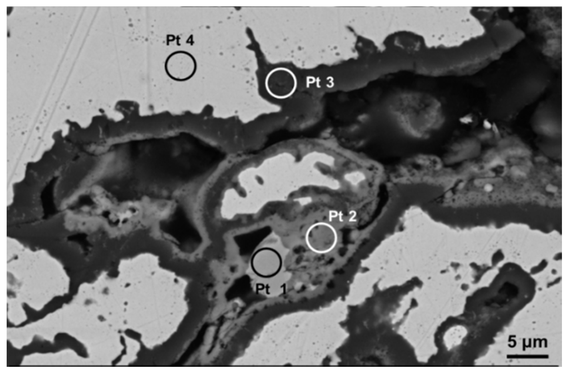
Figure 4 shows a localized area in coating cross section which suffered internal oxidation during next high-temperature aging. The thermal exposure in air environment promoted the partial infiltration of oxygen through the open pores and microcracks located along coating thickness. Therefore, in some regions near the coating surface the penetration of oxygen promoted the Al diffusion from the β-NiAl phase and the following formation of a dark grey Al
2O
3 scale at splat boundary (the surface of metal particles), which typically surrounds the voids. In restricted areas the outward diffusion of Ni and Cr promoted further chemical reactions, leading to the growth of some mixed oxide scales on the Al
2O
3 surface. The growth of secondary oxide phases generally occurred in restricted areas where more pronounced Al depletion did not allow the formation of a stable and protective Al
2O
3 layer, whereas it was less significant in the areas characterized by growth of a continuous and well adherent Al
2O
3 layer.
Figure 4.
A localized area characterized by internal oxidation within the cross sectional microstructure of NiCoCrAlYRe coating. After high-temperature aging dark grey alumina flakes grow at splat boundary and are somewhere supported by grey spinel-type porous oxides, whereas NiO appears in form of light grey precipitates embedded in the spinel phase.
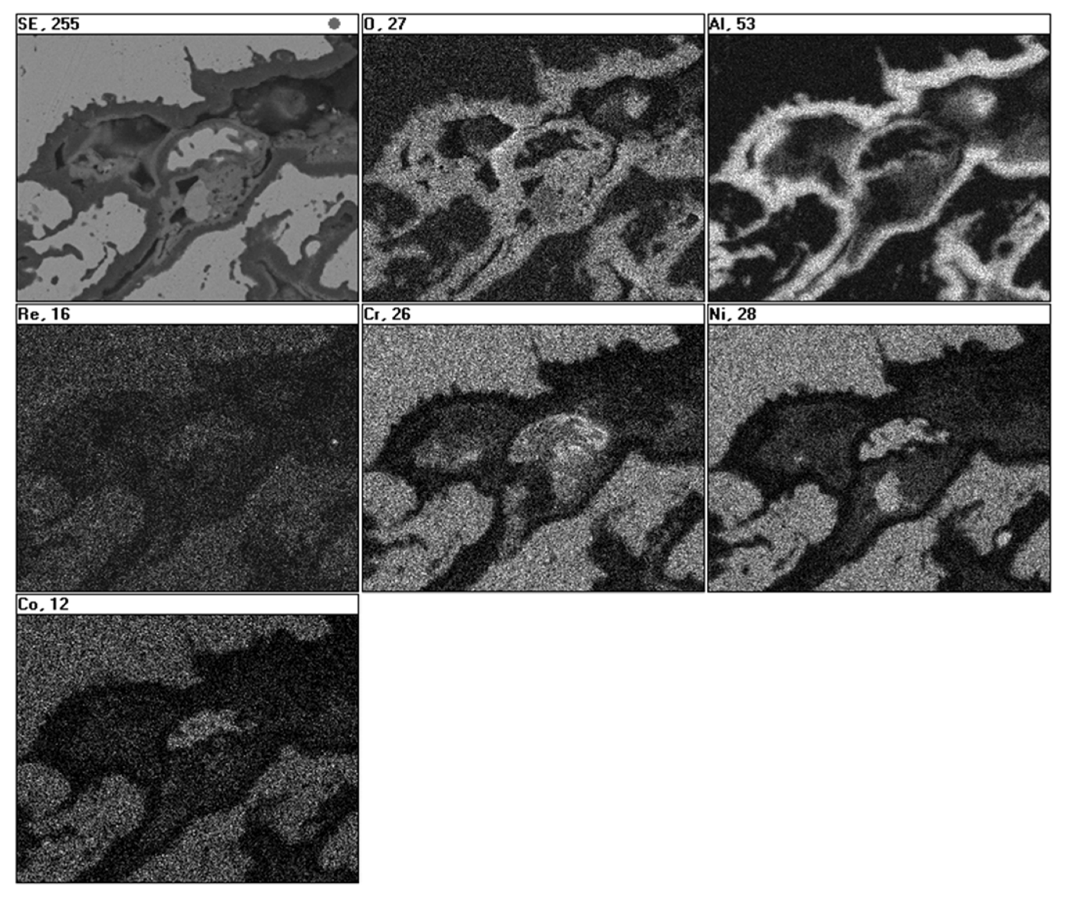
Figure 5 reports the EDS maps related to the area presented in
Figure 4, demonstrating the formation of Al
2O
3 oxide scale at splat boundary as well as the formation of Cr
2O
3, Ni(Cr,Al)
2O
4 (medium grey phase) and NiO (light grey) at lesser extent in any localized areas with lower Al content [
20]. It should be noted that the maps of Ni, Co, Cr and Re are well matched, thus suggesting the uniform distribution of these elements within the γ matrix.
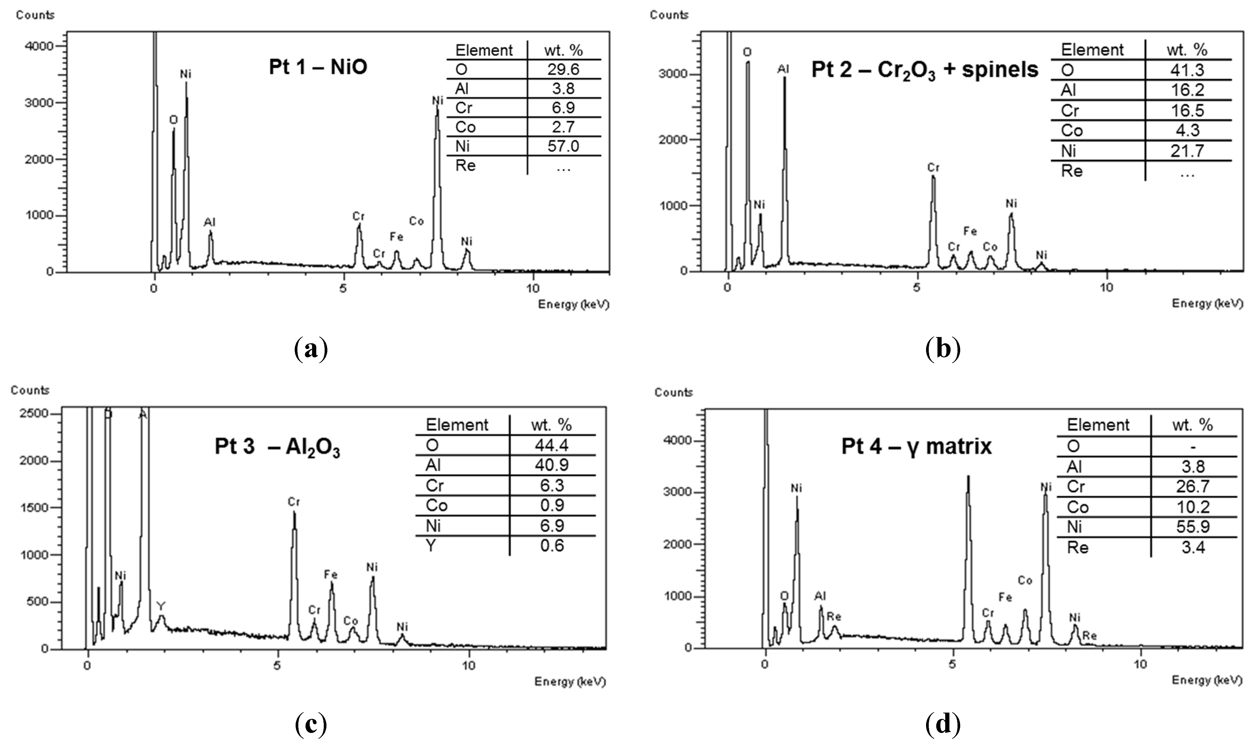
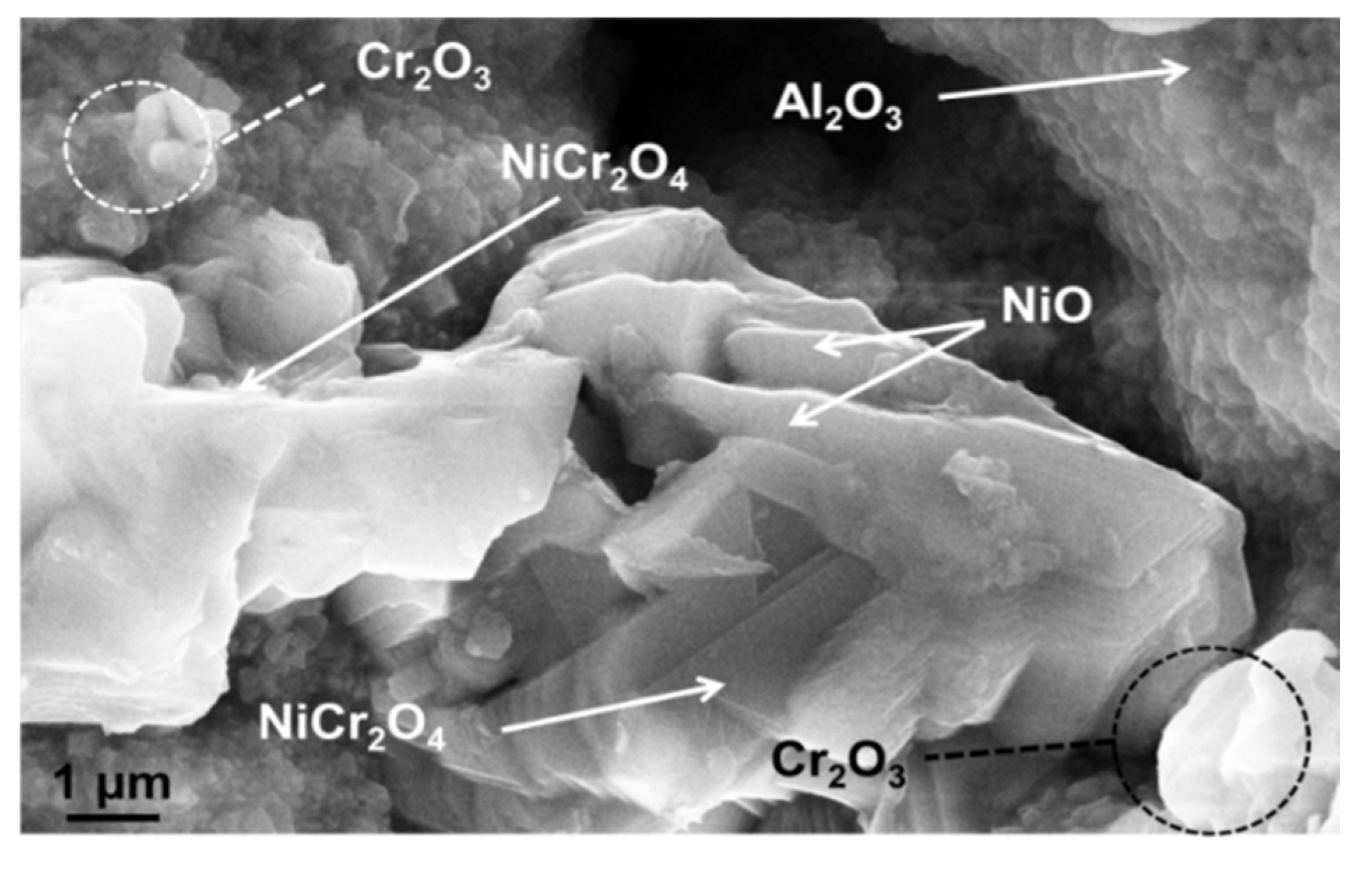
Figure 6 reports the EDS spectra related to different regions identified in coating microstructure, and denoted by circled areas in
Figure 4. These spectra are compatible with the presence of NiO, Cr
2O
3 + spinels, Al
2O
3 and γ matrix, respectively. In the Pt2 area a significant amount of Al (~8 wt%) was also found, this suggesting the presence of Al
2O
3 and NiAl
2O
4. In turn the presence of Cr suggested the formation of Cr
2O
3 and NiCr
2O
4. Otherwise, the wt% of Al in the depleted γ phase was found to be close to 4%, this suggesting a depletion of Al to form Al
2O
3 oxide at splat boundary. A slight decrease of Cr content has been noticed in the areas near the oxide layer, due to Cr diffusion and formation of its oxides. As clearly displayed in the elemental maps reported in
Figure 5 as well as in the EDS analyses shown in
Figure 6, the rhenium is uniformly distributed in the depleted γ matrix and its wt% was found to be 3.9% ± 0.5%, slightly higher than the related content observed in the matrix before high-temperature exposure (3.3 wt%), this suggesting Re diffusion from the β phase. Otherwise the presence of Re could not be observed in the oxidized areas. It is reasonable to suppose that Re was not directly affected by formation of its oxides, even if the formation of volatile Re
2O
7 could not be excluded. However, the addition of Re to the metal alloy played a positive role on the oxidation resistance, promoting better diffusion of Al and lower diffusion of other elements such as Ni and Cr, so that Al
2O
3 was the major oxidation product.
Figure 5.
EDS maps showing the distribution of the elements in the oxidized region shown in
Figure 4. Dark grey alumina scale grows at splat boundary and is somewhere supported by irregular grey mixed oxides.
Figure 5.
EDS maps showing the distribution of the elements in the oxidized region shown in
Figure 4. Dark grey alumina scale grows at splat boundary and is somewhere supported by irregular grey mixed oxides.
Figure 6.
EDS spectra of different spot areas localized in coating microstructure, indicating the presence of (a) NiO; (b) Cr2O3 + spinels; (c) Al2O3; and (d) γ matrix.
Figure 6.
EDS spectra of different spot areas localized in coating microstructure, indicating the presence of (a) NiO; (b) Cr2O3 + spinels; (c) Al2O3; and (d) γ matrix.
The most significant chemical reactions occurring during high-temperature exposure can be summarized as follows:
As also reported by other authors, the spinel phases were formed because of reaction between Cr
2O
3 (or Al
2O
3) and NiO [
20]. Based on the XRD results and phase composition study reported in a previous work as well as on the EDS analysis herein discussed it could be supposed that the spinel phase was mainly composed of NiCr
2O
4 [
21].
It should be noted that it was very arduous to provide the exact composition of the various oxide scales detected, because their composition locally changed and the small volume considered for EDS measurements affected the quantitative results.
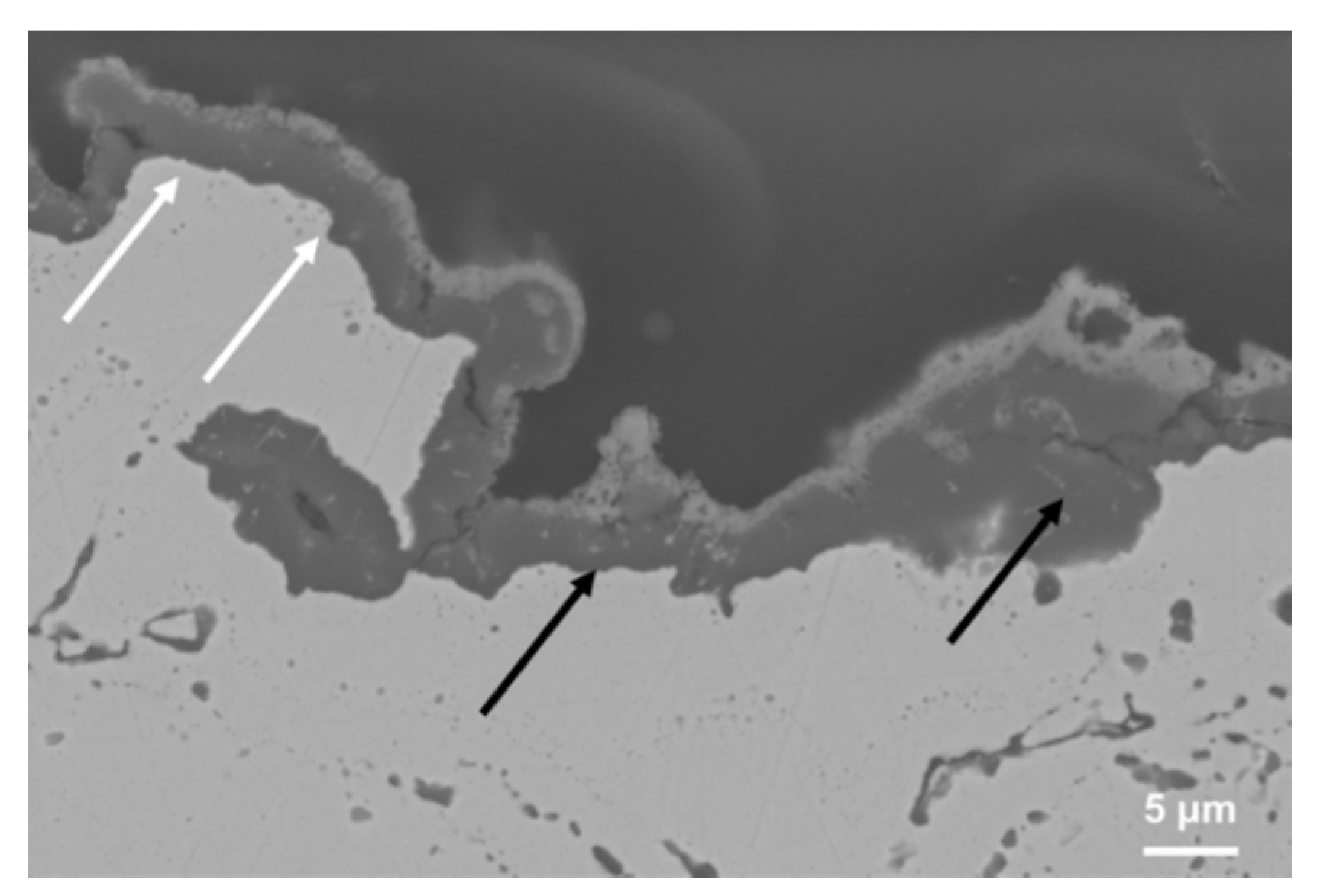
Figure 7 shows the cross-sectional microstructure near coating top-surface after early stage oxidation and suggests the formation of a double oxide scale, composed of an inner nearly continuous and dense alumina layer, followed by an upper and more brittle thin mixed oxide layer. As the oxidation time increased the formation of the Al
2O
3 scale on the coating surface occurred according to Equation (2). Al
2O
3 was the most thermodynamically stable oxide, so that Al
2O
3 mainly tended to grow after a continuous TGO was developed. However, when Al was depleted to a certain extent near the coating top-surface Ni and Cr partially infiltrated through some cracks at nano scale across the growing Al
2O
3 layer, thus forming their oxides (NiO and Cr
2O
3) as well as spinels, via solid state reaction with pre-existing Al
2O
3 and C
2O
3 according to Equation (5). It is reasonable to suppose that the effect of the outward diffusion of Ni and Cr through the growing alumina layer was predominant with respect to that produced by inward oxygen infiltration, so that the mixed layer grew on the same Al
2O
3 layer. In addition, NiO and Cr
2O
3 could be formed at lesser extent in conjunction to Al
2O
3 during the first stage of thermal aging and then could react with the same Al
2O
3 to form spinels on the external surface.
Figure 7.
Cross sectional SEM microstructure of oxidized NiCoCrAlYRe coating showing the formation of a double oxide scale on the top-surface, composed of an inner continuous Al2O3 scale supported by an upper mixed oxide layer.
Figure 7.
Cross sectional SEM microstructure of oxidized NiCoCrAlYRe coating showing the formation of a double oxide scale on the top-surface, composed of an inner continuous Al2O3 scale supported by an upper mixed oxide layer.
For this purpose the presence of the first stable alumina layer allowed for reduction of further oxygen infiltration, partially preventing the effect of internal oxidation, while the presence of the upper layer can represent a disadvantage, because some surface protrusions, derived from its fast and heterogeneous growth, and the thermal stresses herein originated can cause microcracking and delamination. However, if the coating had preserved a sufficient Al activity to allow the rehealing of the protective Al2O3 scale, the spallation of the outer mixed oxide layer does not represent a critical factor during the first hours of operation.
Otherwise, the same effect should be carefully taken in account when a ceramic TBC is applied on the NiCoCrAlYRe coating, because the thermal stresses generated at the interface and the horizontal microcraking can reduce the adhesion and thus promote unexpected TBC spallation during long-term service [
22]. It is worth noting that the presence of a rough surface rich of asperities can partially impede the formation of a stable and continuous Al
2O
3 layer, allowing the fast formation of mixed oxide scale with embedded pores and microcracks. Indeed, as shown in
Figure 7 the convex surface areas along the top-surface are characterized by the growth of a thin Al
2O
3 scale with an outer very thin spinel-type oxide scale (see the white arrows in the picture), while in the concave surface areas a thicker double oxide scale grew quickly, producing some surface protrusions, tensile stresses and microcracking (see the black arrows in the picture). High surface roughness increases the specific surface area for oxidation and also reduces the adhesion of the oxide scale during long-term service, as previously investigated [
23].
The formation of mixed oxides has been also found in MCrAlY coatings deposited under vacuum atmosphere or by HVOF spraying and aged at 1000–1100 °C [
24,
25,
26] and cannot be totally prevented, so that it is an important key issue to reduce their growth and to have a well adherent and dense oxide scale mostly composed of Al
2O
3 with low oxygen diffusivity, and able to reduce permeation of Ni and Cr as well as further oxygen infiltration. For this purpose the NiCoCrAlYRe particles have been herein processed to fabricate coatings with the above mentioned two phase structure, by reducing in-flight oxidation at their external surface and thus preventing Al depletion. The resulting high retention of β precipitates in the matrix allows for controlling at some extent the oxide scale formation during next high-temperature exposure. High process gas flow (Ar + H
2 = 65 slpm) and Ar/H
2 ratio (~6) were employed for melting and transport of melted particles in the plasma jet, in order to prevent metal surface oxidation during processing in air environment.
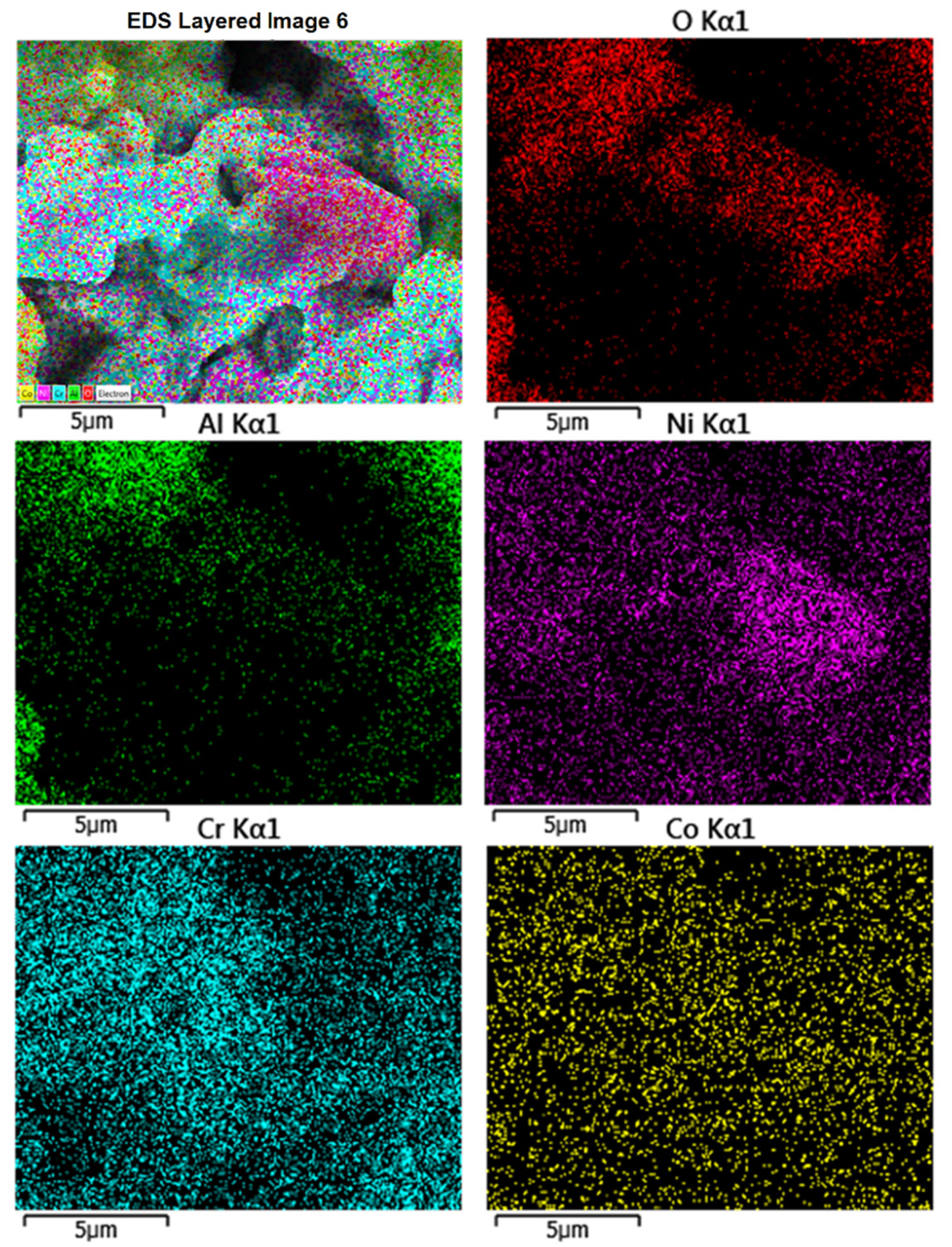
The simultaneous presence of different oxides can be also appreciated from the analysis of
Figure 8 and
Figure 9. According to the EDS maps the presence of Al
2O
3 can be noticed as well as the formation of light grey structures particularly enriched in Cr.
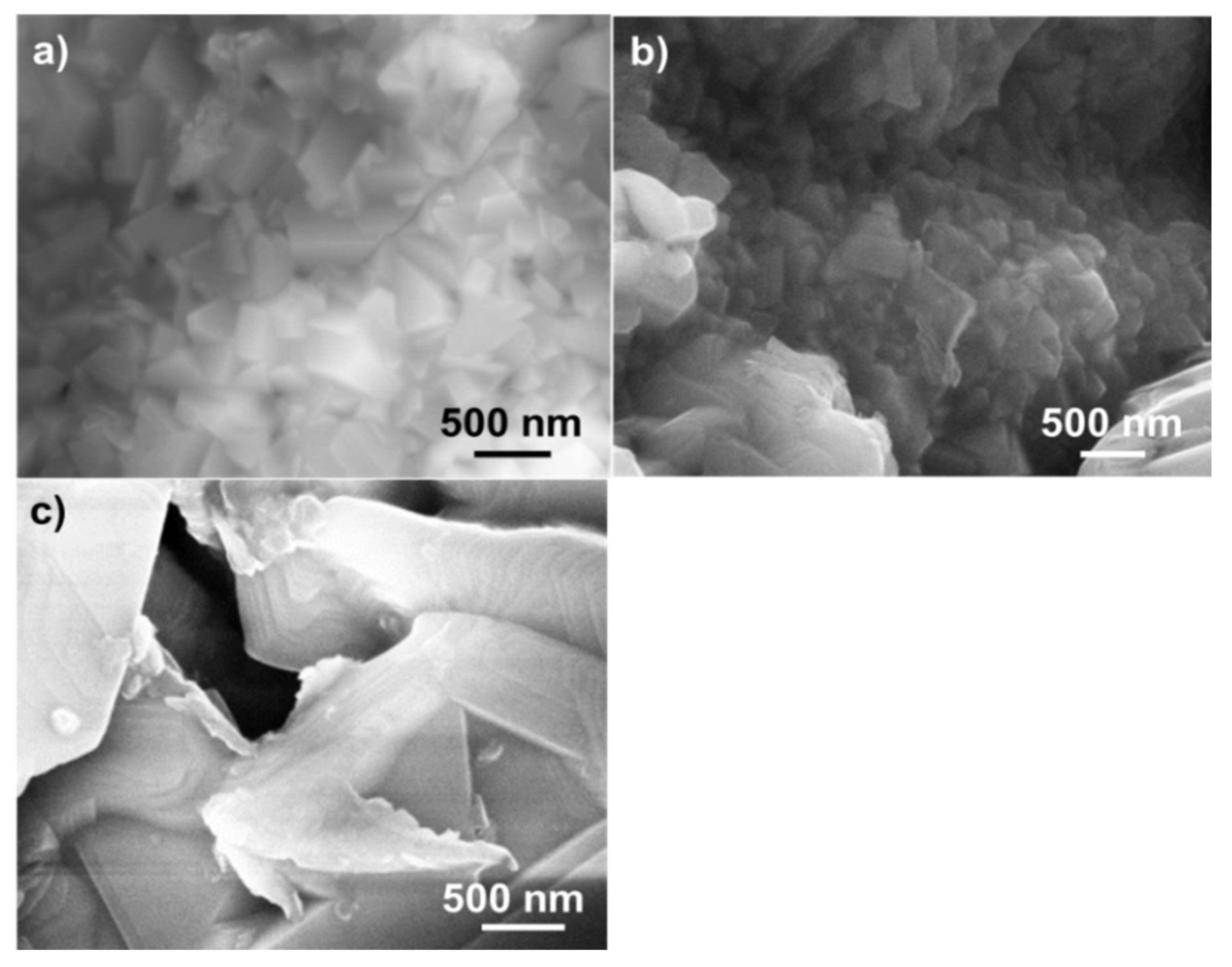
Figure 10a shows some metallic grains with size close to hundreds of nanometers and located below the TGO layer. The surface oxide layer was mechanically removed to observe their morphology and to calculate their composition, which was close to that of the depleted γ phase (see, for example, the graph 4 reported in
Figure 6). Columnar and equiaxed grains of Al
2O
3 can be observed in the center of
Figure 10b. In turn,
Figure 10c shows some different structures larger than 1 μm and composed of a mixture of NiCr
2O
4 and NiO (see also the elemental map in
Figure 8).
Figure 8.
EDS maps of a localized region on the oxidized coating top-surface. The formation of mixed oxide scales composed of Ni, Al and Cr can be appreciated.
Figure 8.
EDS maps of a localized region on the oxidized coating top-surface. The formation of mixed oxide scales composed of Ni, Al and Cr can be appreciated.
Figure 9.
A localized area on oxidized coating top-surface characterized by the presence of mixed oxides grown on the surface of Al2O3 grains. NiO and spinels show polygonal and equiaxed shape, respectively.
Figure 9.
A localized area on oxidized coating top-surface characterized by the presence of mixed oxides grown on the surface of Al2O3 grains. NiO and spinels show polygonal and equiaxed shape, respectively.
Figure 10.
SEM morphology of (a) metal grains after removal of the oxide layer; (b) Al2O3 grains grown at the boundary of metal particles; and (c) mixed oxide scales with polygonal (NiO) and equiaxed shape (spinels).
Figure 10.
SEM morphology of (a) metal grains after removal of the oxide layer; (b) Al2O3 grains grown at the boundary of metal particles; and (c) mixed oxide scales with polygonal (NiO) and equiaxed shape (spinels).
Generally, the NiO scale exhibited granular or polygonal/elongated shape, while spinels and Cr
2O
3 were present in form of equiaxed grains. The presence of these mixed oxide structures was appreciated in restricted and small areas where Al exhibited a reduced activity and its concentration was not enough to promote the selective formation of the preferable Al
2O
3 scale [
20]. Based on the results discussed herein, the addition of Re to the NiCoCrAlY alloy allows for prevention of Al depletion during processing, thus involving high retention of β phase in the as-sprayed coating. Therefore, it plays a beneficial role on the related oxidation resistance at high temperature by improving Al diffusion and reducing the outward diffusion of elements like Cr and Ni. In other words, the presence of Re in the microstructure is useful to promote the formation of a protective, well adherent, dense and quasi continuous Al
2O
3 layer at metal surface, so that the formation of mixed oxide scales is reduced at lower extent as well as the internal oxidation occurring at splat boundaries. Therefore, the β phase depletion and the oxidation rate of MCrAlYRe coatings are lower with respect to the conventional MCrAlY ones [
6]. The addition of Re influences the morphology and the amount of the phases into the coating.
The studies concerning the composition and the microstructure of NiCoCrAlYRe overlay coatings can potentially affect their temperature capability and durability under different scenarios and be addressed to applications in power plants and aircraft engines. For this purpose, the systems used for propulsion typically experience multiple thermal cycles, whereas the power systems largely operate in isothermal mode with a few cycles. In addition the oxidation rate and the TGO growth become more critical when a ceramic TBC is applied on the metal coating, because the formation of the TGO at the interface between bond coat and top coat strongly affects the adhesion and the failure of the same TBC. Apart from the different operating conditions (temperature, cycling, presence of corrosive media and coating architecture) the oxidation mechanism of the metal coatings—including type, thickness, morphology and adhesive strength of the TGO—should be controlled at some extent to enhance coating performance.


