Article

Enhanced Adhesion of Continuous Nanoporous Au Layers by Thermochemical Oxidation of Glassy Carbon

Department of Chemistry, Binghamton University, PO Box 6000, Binghamton, NY 13902-6000, USA
*
Author to whom correspondence should be addressed.
Coatings 2014, 4(3), 416-432; https://doi.org/10.3390/coatings4030416
Submission received: 12 June 2014 / Revised: 27 June 2014 / Accepted: 3 July 2014 / Published: 9 July 2014

Abstract

:
The fabrication of a nanoporous gold (NPG)-based catalyst on a glassy carbon (GC) support results normally in large isolated and poorly adhering clusters that suffer considerable material loss upon durability testing. This work exploits thermochemical oxidation of GC, which, coupled with the utilization of some recent progress in fabricating continuous NPG layers using a Pd seed layer, aims to enhance the adhesion to the GC surface. Thermochemical oxidation causes interconnected pores within the GC structure to open and substantially improves the wettability of the GC surface, which are both beneficial toward the improvement of the overall quality of the NPG deposit. It is demonstrated that thermochemical oxidation neither affects the efficiency of the Au0.3Ag0.7 alloy (NPG precursor) deposition nor hinders the achievement of continuity in the course of the NPG fabrication process. Furthermore, adhesion tests performed by a rotating disk electrode setup on deposits supported on thermochemically-oxidized and untreated GCs ascertain the enhanced adhesion on the thermochemically-oxidized samples. The best adhesion results are obtained on a continuous NPG layer fabricated on thermochemically-oxidized GC electrodes seeded with a dense network of Pd clusters.

1. Introduction

1.1. Nanoporous Gold (NPG)-Based Catalyst on Glassy Carbon (GC)

A specific nano-material that has gained recent interest is nanoporous gold (NPG). NPG is a three-dimensional, continuous Au structure featuring interconnected nanosized pores and ligaments [1]. It is a conductive material that contains a very high surface area (SA) per unit mass, characteristic of nano-materials and comparable to that of nanoparticles (NPs) [2]. Independent of the synthetic routine employed, NPG is a fairly tunable material in the course of controlled fabrication and post factum [1]. NPG has been known and studied for many years, but the increased interest in the last decade largely stems from its versatility and numerous applications, across many disciplines, including electrochemistry, analytical chemistry and materials science, with emphasis on sensing and electrocatalysis [2,3,4,5].
It has been shown recently that ultra-thin films of NPG can serve as catalysts for fuel cell applications as an alternative to their nanoparticle (NP) counterparts [6,7,8]. Some advantages of those films are the simplicity of fabrication, the cost effectiveness and better reproducibility in terms of quality and reactivity. Unlike the variety of processing steps leading to insufficient control in nanoparticle synthesis, ultra-thin films are generated electrochemically under precise potential/current control. More specifically, the high level of control in the NPG fabrication process (involving co-deposition and selective dissolution) allows for the minimization of the material loss and surface contamination inevitable for the multi-step NP synthetic routines [7,9]. Finally, the continuous nature of NPG films preserves their catalytic functionality from the edge effect, which is known to lower the catalytic activity characteristic of NP-based catalysts [10].
Aiming at maximizing the effect of the above listed advantages, our group recently reported an all-electrochemical synthetic method for an NPG-based catalyst [7]. This method includes Au(1−x)Agx alloy electrodeposition followed by selective dissolution of Ag (de-alloying) to generate the desired NPG structure of a thickness less than 20 nm [7]. For application in formic acid oxidation catalysis, NPG is functionalized with Pt by surface-limited redox replacement (SLRR) [11] to form Pt-NPG. Relying structurally on its interconnected porosity and featuring enhanced activity boosted by the catalytic synergism between Pt and Au [12,13], Pt-NPG constitutes a cost-effective alternative to Pt fabricated on Au and glassy carbon (GC) substrates. The Pt-NPG catalyst demonstrated high mass activity (1–3 A·mg−1 of combined catalyst) and a reasonable catalyst life (2600 standard formic acid oxidation cycles). These tests ascertained a satisfactory performance in stability tests [7]. However, the catalyst fabrication and its further assessment revealed issues and challenges associated mainly with the use of GC substrates. Specifically, we were unable to achieve a continuous layer of NPG on GC, unlike the continuous NPG films that have been synthesized on Au (and other metal substrates), which feature properties that are identical to bulk Au. Instead, a low-density cluster deposit of NPG was fabricated on GC, which was attributed to the poor surface catalytic activity [14]. The poly-disperse spherical particles are the representative outcome of conventional synthetic routines on GC electrodes [15]. Contrary to the expectation that electrodeposition would generate alloy deposits that adhere better to the GC than physically adsorbed NPs, a considerable loss of NPG spherical clusters was observed during performance testing of accordingly fabricated Pt-NPG catalysts [7]. This issue was addressed by the development of routines for the fabrication of a continuous ultra-thin film of NPG on GC with the additional goal of improving the adhesion by decreasing the NPG mass per point of contact with the surface [16]. However, even the successful fabrication of perfectly continuous NPG films (which constitutes an achievement by itself [17]) was unable to completely resolve the adhesion issue, despite the certain noticeable improvement of the overall catalyst stability during testing.

1.2. Thermochemical Oxidation for Improved Adhesion

Efforts toward enhancing the adhesion of metals to the surface of GC in order to optimize its use as a carrier in catalysis have shown that oxidation is a promising approach. Two types of oxidation have been reported in the literature: thermochemical and electrochemical. Thermochemical gas phase oxidation exposes the GC substrate to air (functioning as the oxidant) at temperatures in the range of 400–600 °C. This protocol was first reported by Siemens in 1980 [18], and the thermochemically-oxidized glassy carbon (TOGC) was usedtoward the development of an electric double-layer capacitor. This protocol was further explored [19] and eventually included the application of activated GC as the carrier/support for electrocatalytic materials [20,21].
In its unaltered state, GC is considered to be a nonporous, impermeable material [22,23]. At the same time, pores located within the material are closed and can therefore be considered as voids within the impermeable structure. The process of thermochemical oxidation opens these pre-existing pores, which coalesce and form larger pores to ultimately increase the surface area of the substrate [24]. This modification of the surface increases the density of homogenously distributed surface defects and imperfections, which can serve as nucleation sites during electrodeposition. This, in turn, leads to enhanced nucleation density in comparison with untreated GC counterparts [20].
Savouchkina et al. were the first to utilize TOGC as a substrate for Pt electrodeposition [20]. It was reported that as the thermochemical oxidation time increased, Pt coverage also increased. In addition, it was also reported that the presence of pores on the substrate inhibited Pt diffusion and promoted three-dimensional growth. Thus, it was apparent that thermochemical oxidation did not facilitate the growth of a continuous thin film of Pt in this study.

1.3. The Paper’s Objective

While work toward the generation of an oxide layer and the opening of micro-pores on a GC surface during thermochemical oxidation had been explored and occasional reports touch upon the nucleation density and the adhesion of metal deposits, none of these studies have reported on the effect of thermochemical oxidation on the continuity and adhesion of Au and NPG deposits on GC. This paper is aimed at utilizing thermochemical oxidation for the fabrication of robust and continuous NPG layers featuring enhanced adhesion to the GC substrate. Based on previously developed routines [7,15], the synthetic and characterization research will primarily focus on: (i) the morphology and continuity of the GC layer as a result of the thermal oxidation substrate studied by scanning electron microscopy (SEM); (ii) the wettability of thermochemically-oxidized GC surfaces assessed by contact angle measurements; and (iii) the adhesion of Au0.3Ag0.7 films on thermochemically-modified and control (untreated) GC substrates by measuring the surface area and the total amount of dissolved Ag before and after subjection to an unsteady environment realized by a rotating disk electrode (RDE) setup.

2. Experimental Section

2.1. Electrode Preparation

Cylindrical glassy carbon working electrodes (Goodfellow, Huntingdon, England; diameter 5 mm) were first mechanically polished down to 1 µm with alumina slurry (Buehler, Lake Bluff, IL, USA) followed by rinsing in Barnstead Nanopure® water (R ≥ 18.2 MΩ·cm) and sonication for 2 minutes in ethanol. After sonication, they were dried under ultra-high purity N2 (less than 1 ppb of O2, CO, CO2 and moisture). These sequential steps encompass the procedure for the preparation of GC electrodes that will be called “untreated” further in this work. In all deposition experiments, the GC electrodes (untreated or subjected to further modification) were brought in contact with the electrolyte in a hanging meniscus configuration.

2.2. Pd Seeding

As polished or thermochemically-oxidized GC electrodes were sensitized for two minutes in a solution containing 10 mM SnCl2 (GFS Chemicals, Powell, OH, USA; 98%) and 0.1 M HCl (JT Baker, Center Valley, PA, USA; 37.2%) to form a uniform layer of adsorbed Sn2+ ions. The GC electrodes were immediately rinsed thoroughly with Barnstead Nanopure® water, dried and then exposed to a solution containing 10 mM (NH4)2PdCl4 (GFS Chemicals, 99.999%) and 0.1 M HCl (JT Baker, 37.2%) for one and half minutes in order to replace the Sn2+ layer with a Pd(II) complex. The Pd(II) complex solution was thoroughly de-oxygenated by purging for an hour with ultra-high purity N2. The GC electrodes were then rinsed thoroughly with Barnstead Nanopure® water again and dried gently under ultra-high purity N2. Finally, the freshly deposited Pd seed was subjected to acceleration by submerging it in a solution containing 10% HCl by weight for three minutes in order to complex any remaining Sn2+. After this, the Pd-seeded GC electrodes were rinsed one final time with Barnstead Nanopure® water and dried.

2.3. Thermochemical Oxidation

After mechanical polishing and thorough removal of all polishing remnants, GCs were subjected to a thermochemical oxidation treatment in a furnace (Model 47900, Barnstead Thermolyne, Dubuque, IA, USA) and heated at 450 °C for 40 minutes. Those electrodes were then used either directly as a support for NPG catalysts or were subjected first to Pd seeding and then used as the NPG support. The former will be referred to as thermochemically-oxidized GCs (TOGCs). The latter will be further referred to as dual-treated GCs (DTGCs).

2.4. Thin Film Alloy Deposition

A Princeton Applied Research (PAR) Model 273 Potentiostat/Glavanostat with Corrware Software was been used to electrochemically deposit Au0.3Ag0.7 thin films with solutions containing 0.6 mM Au(I)Cl (GFS Chemicals, 99.995%) and 1 mM AgClO4 (GFS Chemicals, 99.995%) (3:2 ratio) in 0.1 M Na2S2O3 (Alfa AESAR, Ward Hill, MA, USA; ≥99%). The alloys were electrodeposited on treated and untreated GC samples in a three-electrode cell at a constant potential of 0.200 V versus standard hydrogen electrode (SHE) using Ag/Ag+ pseudo reference electrode (PRE) (~0.600 V, SHE) and a Pt wire as the counter electrode (CE). The cell was purged with ultra-high purity N2 for 20 minutes. The thickness of the films was controlled by the duration of the deposition process carried out under steady-state conditions. An identical amount of deposited alloy with a given composition for all samples was ensured through the determination of the deposition efficiency calculated as the ratio of charge of de-alloyed Ag (see the next step) to the total deposition charge (fixed at 50 mC·cm−2 in all experiments). Following alloy deposition, the samples were rinsed thoroughly with Barnstead Nanopure® water and dried. After deposition, Pb underpotential deposition (UPD) was performed immediately to determine the SA of the deposited thin film alloys [25].

2.5. The De-Alloying Process

Selective removal of Ag from the Au0.3Ag0.7 thin film alloy (de-alloying) carried out by linear sweep voltammetry was used to obtain NPG. The solution used was 1 mM AgClO4 and 0.1 M HClO4 (GFS Chemical, 70% redistilled). The de-alloying experiments were also performed in a three-electrode cell with Pt wire used as the CE. Anodic scans from −0.010 V to 0.850 V versus Ag/Ag+ PRE at a sweep rate of 0.2 mV·s−1 were performed by the PAR Model 273 Potentiostat/Glavanostat with Corrware Software. Normally, the accordingly fabricated NPG layer would feature a thickness of 20–50 nm, depending on the cluster density/continuity of the deposit.

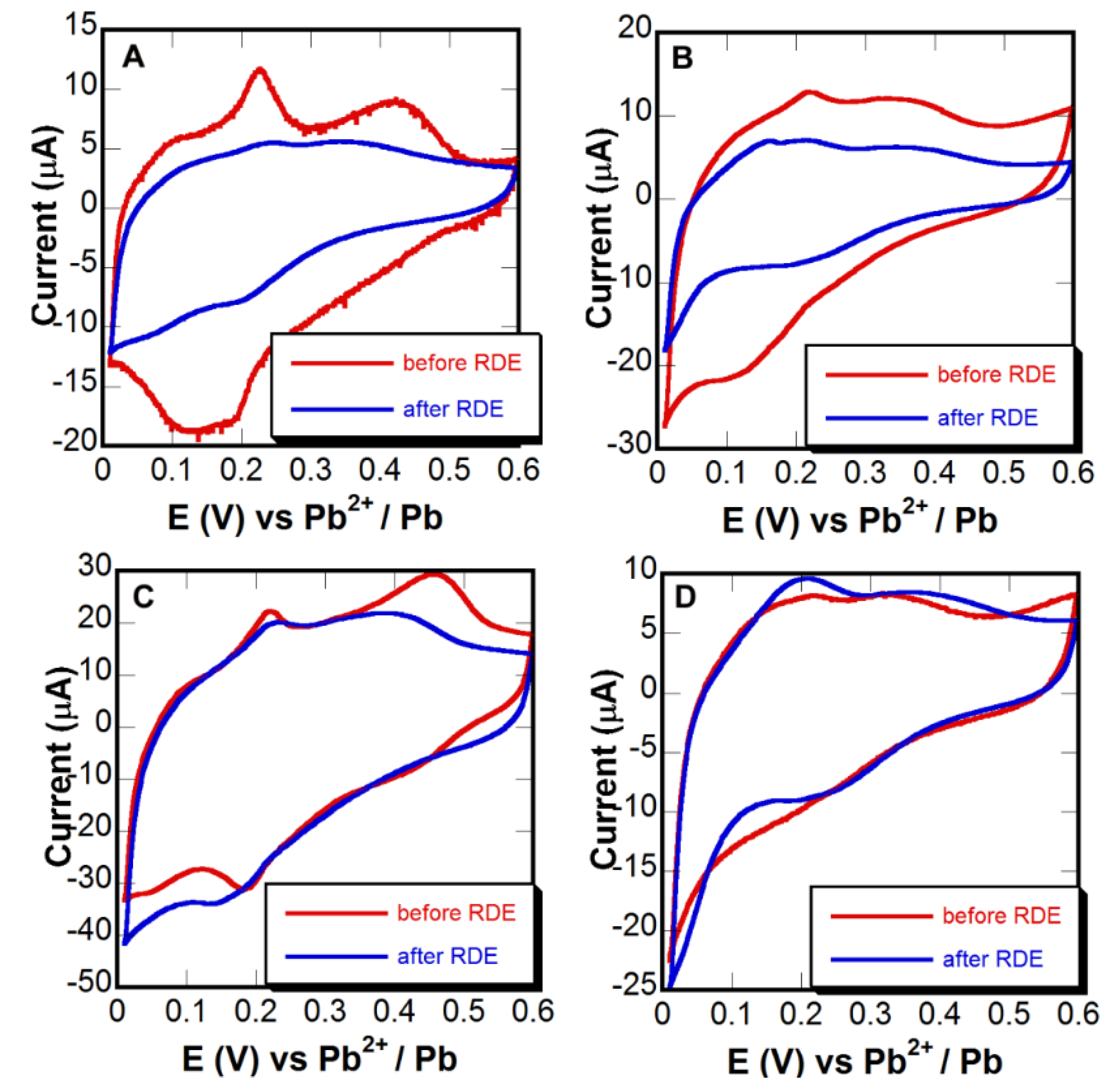
2.6. Surface Area Measurements

Pb UPD was performed immediately after the NPG fabrication (as described in the previous section) and after the adhesion assessment (described in the next section) to determine the SA [25] of as-fabricated and adhesion-assessed samples, respectively. The solution was purged with ultra-high purity N2 for 20 minutes prior to the Pb UPD experiments, and N2 gently passed over the surface of the solution during the anodic scans. The measurements were performed by cyclic voltammetry in a three-electrode cell with a solution containing 0.1 M NaClO4 (Sigma Aldrich, St. Louis, MO, USA; 99.95%), 3 mM Pb(ClO4)2 (Sigma Aldrich, 99.995%) and 0.01 M HClO4. The BASi Epsilon Electrochemical Workstation was used for cycling the potential from 0.600 to 0.010 V at 20 mV·s−1 versus Pb/Pb2+ PRE (−0.200 V vs. SHE). A Pt wire served as the CE.

2.7. Adhesion Assessment

NPG fabricated on modified GC was subjected to rotation for two hours at 1600 rpm in a solution of 0.1 M HClO4 using a Pine MRS Rotator System, which was operated by a Pine MRS Motor Controller. The SA measurements performed on NPG samples before and after the rotation tests were quantitatively compared in order to determine if any material was lost (assuming the structural invariance of NPG). The adhesion assessment was also performed by de-alloying of two identical sets of as-deposited Au0.3Ag0.7 alloy samples (not NPG) before and after rotation, respectively. By comparing the average amount of stripped Ag in both cases, the material lost during the rotation testing was accurately detected.

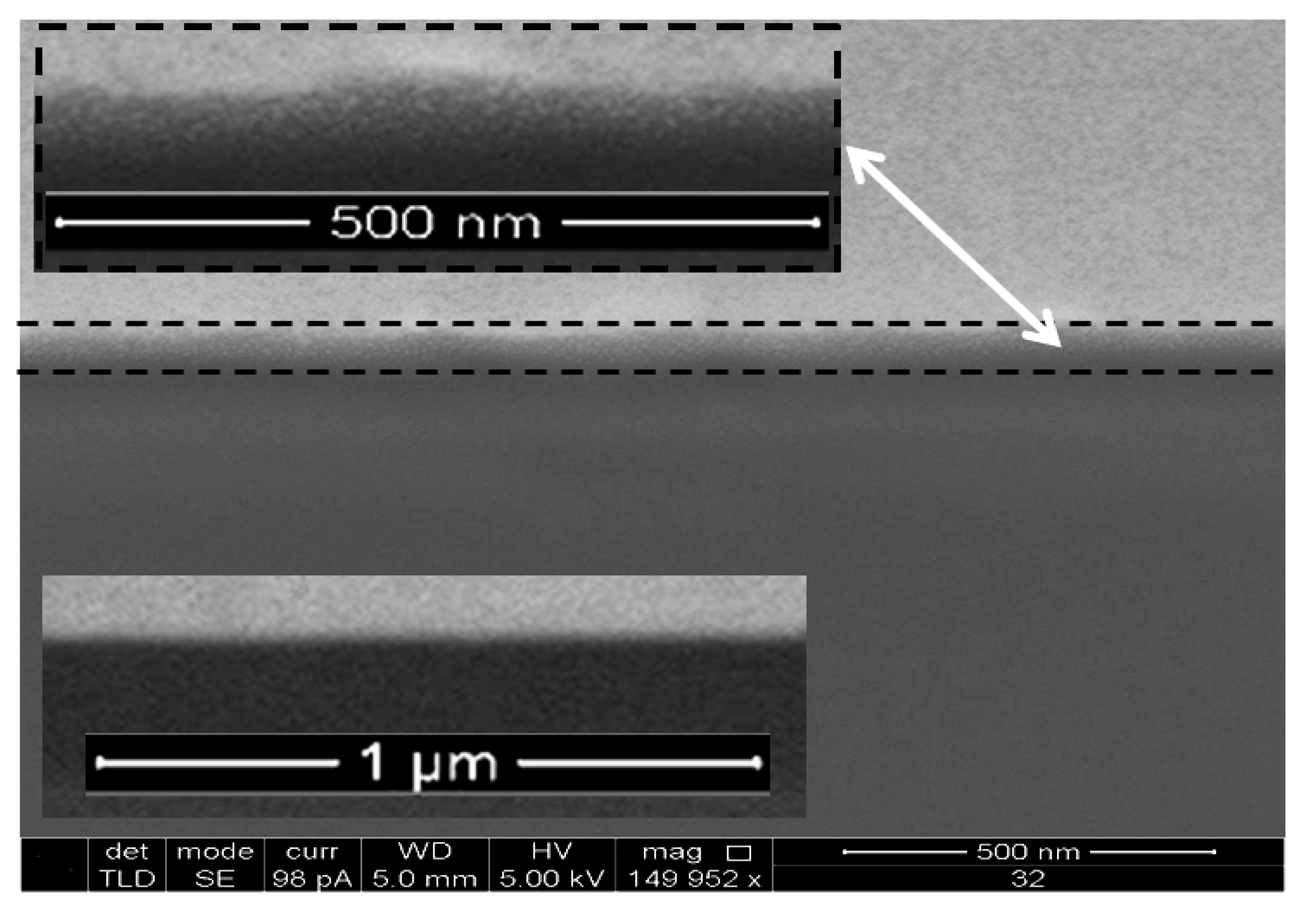
2.8. Scanning Electron Microscopy, Dual-Beam FIB/SEM and Energy Dispersive X-ray Spectroscopy

Scanning electron microscopy (SEM) was performed for the morphological characterization of nanoporous Au on GC substrates. The alloy composition was confirmed by energy dispersive X-ray spectroscopy (EDS) using an FEG-SEM Zeiss Supra 55 VP coupled with a through-the-lens detector at an accelerating voltage of 8–10 kV, used for imaging at magnifications as high as 200,000 times. The working distance was varied depending on the nature of the sample. Furthermore, focused ion beam with scanning electron microscope (FIB/SEM) was used for examining the surface of the thermochemically-oxidized GC surface layer by cross-sectioning. It needs to be noted that prior to generating a hole, the surface of the thermally-treated GC was coated with Pt to prevent surface damage upon removal of the material.

2.9. Contact Angle Measurements

The contact angles (CA) of untreated and thermochemically-oxidized GC samples were measured to determine the hydrophilicity and wettability trends. Furthermore, CA were measured for comparison on electrochemically-oxidized GC sample (EOGC), which is expected to be most hydrophilic [26,27,28]. The electrochemical oxidation was performed for 300 s at a constant potential of 1.47 V vs. Hg/Hg2SO4. The CA measurements were taken using a goniometer and the Drop Analysis LB-ADSA software. A drop of deionized water was placed on the surface of the GC, and the contact angle was determined using the curve fitting software.

3. Results and Discussion

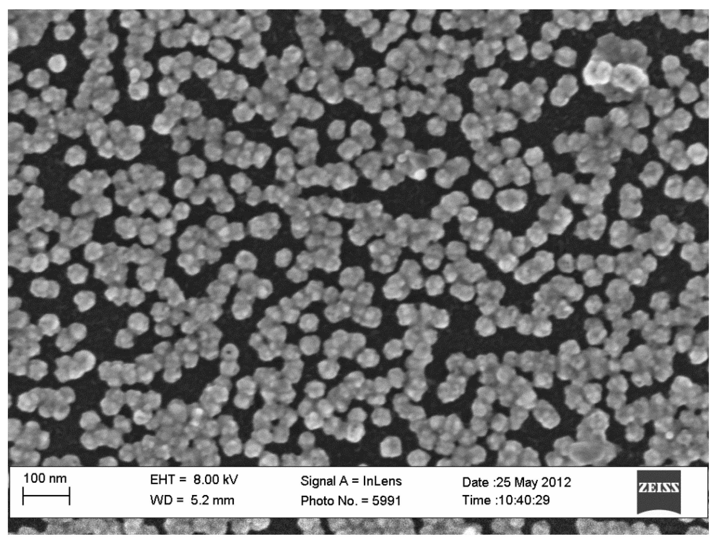
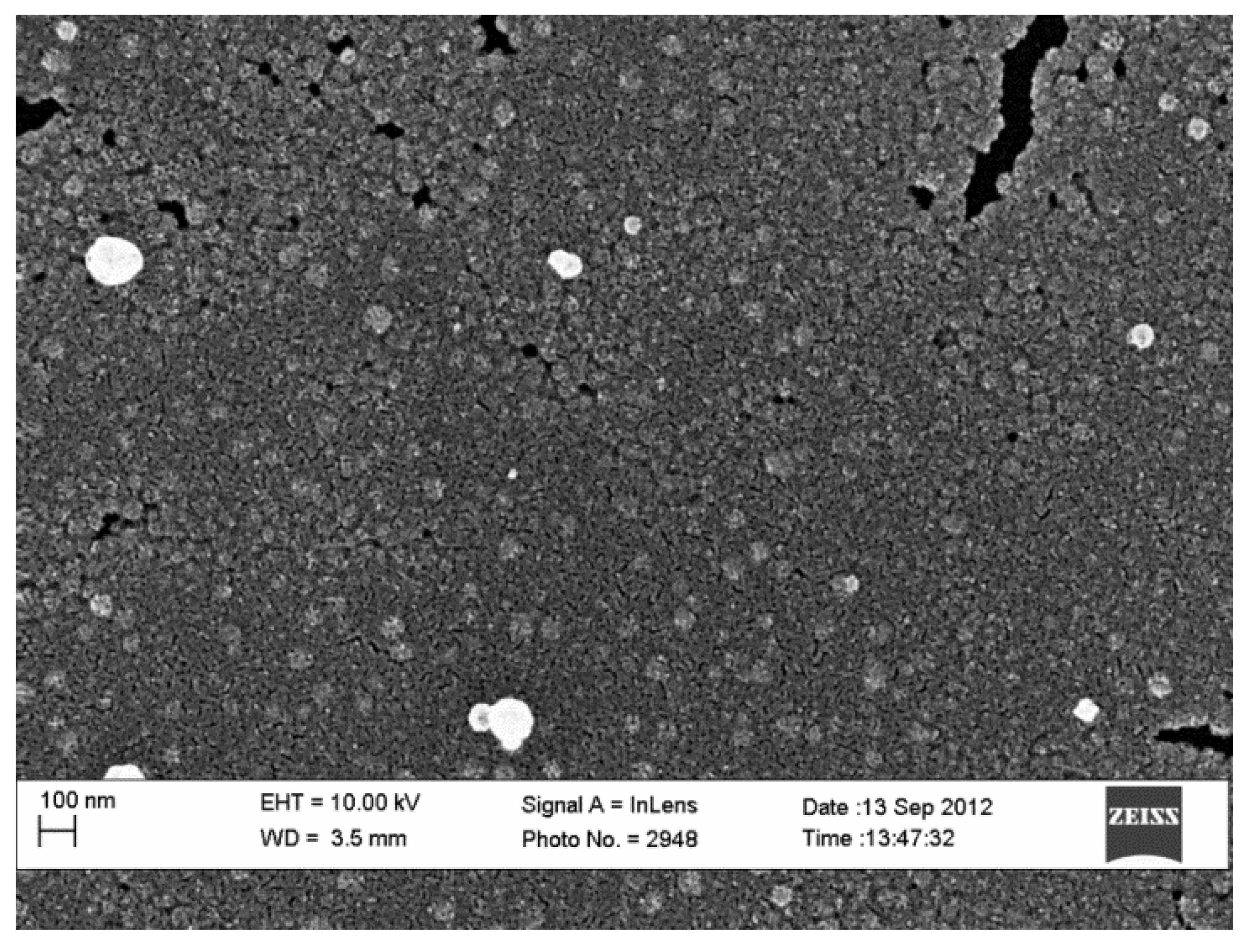
3.1. Nucleation Density

Figure 1 presents an SEM image that illustrates the nucleation density on untreated GC. In accord with earlier work [7,11], NPG forms clusters when fabricated on untreated GC. Nucleation of these NPG clusters, which are about 40–50 nm in diameter, is sporadic. The clusters continue to grow in size as the growth process is supported by the applied deposition potential. Adhesion between the NPG and GC substrate is poor. The fabricated NPG has a tendency to peel off the GC surface during handling. Our previous work utilized a Pd seed layer on the GC (PdGC) to facilitate the fabrication of a continuous layer of NPG [17] and provides a detailed description of the fabrication of a continuous layer of NPG on PdGC. Figure 2 provides an SEM image of the continuous layer of NPG fabricated on PdGC. Unfortunately, the presence of the Pd seed layer did not greatly improve the adhesion between the NPG and GC during performance testing.
Our present work focuses on utilizing the oxidation of GC to enhance the adhesion between NPG and GC. Figure 3 shows an SEM image that illustrates the nucleation density of NPG on thermochemically-oxidized GC (TOGC). In comparison with Figure 1 (NPG on untreated GC), Figure 3 shows that the NPG nanoclusters are larger (~70–80 nm diameter), implying lower nucleation density in this case. This seems to contradict a previous work reported by Savouchkina et al. [20], which showed that thermochemical oxidation of GC enhanced the nucleation density of electrochemically-deposited Pt. The NPG clusters in our experiments are smaller in size than the Pt nanoparticles electrochemically-deposited by pulse-plating (2s) from five times more concentrated solution in Savouchkina’s work [20]. It also appears that the NPG clusters exhibit more uniformity with regard to size. It is likely that the difference in the deposition mechanism (mainly activation controlled in [20] vs. mass-transport controlled in our runs) contributed to the difference in nucleation density. There is also a remote possibility that the nature of the depositing metals in both cases also played a certain role in the initial nucleation and growth of the deposit on the GCs used in both experiments. Finally, the difference in the background electrolytes (thiosulfate in our work vs. sulfate in [20]) could also contribute to the difference in the initial nucleation density in both cases.
Figure 1. SEM image of nanoporous gold (NPG) nanoclusters fabricated on untreated glassy carbon (GC); 50 mC/cm2 total deposition charge density.
Coatings 04 00416 g001
Figure 2. SEM image of a continuous layer of NPG fabricated on Pd-seeded GC; 50 mC/cm2 total deposition charge density.
Coatings 04 00416 g002
Figure 3. SEM image of NPG nanoclusters fabricated on thermochemically-oxidized GC; 50 mC/cm2 total deposition charge density.
Coatings 04 00416 g003
Based on our previous experience, insufficient nucleation density could be addressed by the application of a metal seed prior to the nucleation process [17]. Figure 4 provides an SEM image of NPG fabricated on dual-treated GC (DTGC), which is a GC substrate that is first thermochemically-oxidized and then seeded with Pd using the same method described in our previous work [17]. A continuous thin film was observed for NPG fabricated on DTGC, as shown in Figure 4. This, combined with the results of our previous work, strengthens our earlier finding by confirming that the Pd seed layer is instrumental in the deposition of a continuous thin film on GC, even after the thermal treatment [17].
Figure 4. SEM image of NPG on dual-treated GC (DTGC). The NPG sample was fabricated using a de-oxygenated Pd seeding solution, as well as a de-oxygenated deposition solution; 50 mC/cm2 total deposition charge density.
Coatings 04 00416 g004
The most recent model for the structure of GC is a fullerene-type microstructure suggested by Harris [29]. This model is based on high-resolution SEM micrographs, which revealed tightly curled carbon layers and enclosed nanopores. This model also attributes to the specific structure the impermeability and low reactivity of GC, particularly in comparison with other carbon materials. The presence of closed pores within the GC structure has been suggested by most models and is accepted as a characteristic of GC [29,30]. Following thermochemical oxidation, the GC surface appeared to be unchanged to the naked eye, which was expected, because the porosity of the active surface is at the microscale [31]. Although the exact structure of GC is unknown, several models implying a certain organization and agreeing on the mechanical stability of the active layer have been proposed [30,32].
Based on the results shown in the literature, as well as the cross-sectional SEM images presented in Figure 5, we believe that thermochemical oxidation opens the pores at the surface of the GC. Indeed, Figure 5 presents a cross-section of a TOGC electrode, where the top portion shows a Pt coating layer, the bottom portion presents the GC bulk unaffected by the thermal treatment, and the darker layer between these two is the result of the thermochemical oxidation (indicated by the lines and arrow). A closer inspection of this layer (Figure 5, upper inset) reveals a diffuse boundary between the treated surface and the Pt coating. The diffuse appearance could be associated with a certain amount of Pt slightly penetrating through the opened pores beneath the GC surface. Support for such an interpretation is provided by the lower inset in Figure 5, whereby the untreated control GC sample with no open pores features a sharp interface with the Pt coating. The presumed pore opening upon thermal treatment leads to the roughening of the GC electrode and, thereby, improves the interaction of deposited clusters with the modified surface.
Figure 5. Focused ion beam (FIB)-SEM cross-section of the thermally-oxidized GC electrode. The upper portion represents Pt coating deposited prior to cross-sectioning. The dashed lines confine the layer, resulting from thermochemical oxidation. Upper Inset: a higher magnification image of the Pt/GC interface. Lower Inset: a higher magnification image of the Pt/untreated GC’s interface (for comparison).
Coatings 04 00416 g005
During fabrication of NPG, AuAg nucleates on the surface of TOGC, including within the open pores. These pores appear to be nano- to micro-scale pits at the surface of TOGC, as illustrated in Figure 6a. When GC is coated with a Pd seed layer, the seed layers are situated on top of the GC surface, as illustrated in Figure 6b. The Pd seeds function as nucleation sites for AuAg clusters during the fabrication of NPG. The presence of a high-quality Pd seed layer with evenly spaced and dense Pd clusters is essential to obtain a continuous layer of NPG [17]. It appears that neither the roughening of the GC surface (through pore opening) nor the very low concentration of oxygen anticipated as a result of the thermal treatment [20] in open air served as obstacles to the continuity of the obtained NPG layer, as shown in Figure 4. We believe that, during dual treatment, the seed layer is accommodated in the opened pores, as illustrated in Figure 6c. AuAg then grows on top of the dense and uniformly dispersed seed layer, which enables the fabrication of a continuous NPG film.
Figure 6. Illustration of the surface of: (A) thermochemically-oxidized GC (TOGC); (B) Pd-seeded GC (PdGC); and (C) dual-treated GC (DTGC).
Coatings 04 00416 g006

3.2. Contact Angle Measurements

Figure 7 shows representative picture of the measurement of the average equilibrium static contact angle (CA) on untreated and oxidized GC samples and provides in the caption the contact angles, as well. Untreated GC (Figure 7a) is a hydrophobic surface with an average CA of 84° ± 3°. The images in Figure 7 show the impact of different treatments to the CA and wetting properties of the GC surface, respectively. For that purpose, an electrochemically-oxidized GC sample (EOGC), which is expected to develop surface oxide and, thus, become more hydrophilic [26,27,28], is also included as a reference in the CA measurements (Figure 7c). The EOGC samples feature a CA of about 35° ± 7°. The large difference in CAs between untreated GC and EOGC indicates a significant increase in hydrophilicity caused by electrochemical oxidation. The increase in hydrophilicity is likely caused by a combination of quinone-like functional groups [26,33]. The results also show that thermochemical oxidation (Figure 7b) has a relatively limited impact on the hydrophilicity enhancement in comparison with electrochemical oxidation. TOGC has an average CA of 51° ± 10°.
Figure 7. Images of equilibrium static contact angle (CA) measurements for: (A) untreated GC, CA (84° ± 3°); (B) thermochemically-oxidized glassycarbon (TOGC), CA (51° ± 10°); and (C) electrochemically-oxidized GC (EOGC), CA (30° ± 6°).
Coatings 04 00416 g007
The nearly 30º difference between TOGC and untreated GC suggests a significant increase in hydrophilicity caused by thermochemical oxidation, although not as significant as electrochemical oxidation. Most likely, the limiting low CA of the EOGC sample should be associated with the documented presence of the oxide termination layer, which is known to increase hydrophilicity. On the other hand, based on the results and the literature [31,34], we believe it is likely that thermochemical oxidation primarily causes morphological changes to GC manifested mainly by pore opening and contributing to a surface roughness evolution in TOGCs. This, along with the limited or virtually non-existent oxide on the TOGC surface, points toward considering the roughness evolution as the main cause of the decrease in CA. By assuming homogeneous wetting of rough surface and following the classical Wenzel model [35], one could rationalize the CA decrease in the case of the TOGC sample [36]. A certain minor contribution to the CA trends could be associated with insufficient cleanliness of the untreated GCs, leading to a difference in the chemical surface composition with TOGCs. However, the overall implication of the CA measurements is that both thermally- and electrochemically-oxidized GCs facilitate the deposition of metals and better accommodate the deposits, owing to the enhanced hydrophilicity.

3.3. Adhesion Tests

Figure 8 summarizes the results of adhesion testing of NPG deposits through the recording of Pb UPD cyclic voltammetry (CV) curves [25] before and after the rotation of differently-treated GC samples. Assuming no morphological changes took place during rotation (no potential was applied during testing), the surface area should be proportional to the amount of material present upon potential cycling. Integration of the CV curves provides the charge of formation and stripping of a Pb UPD layer that conformally coats the surface and could thus be directly used for SA measurements. Thus, adhesion test data could be obtained by the integration of CV curves recorded before and after rotation and comparison of the accordingly obtained charges, respectively. Figure 9 provides additional information on the material loss from as-deposited Au0.3Ag0.7 alloys, utilizing the results of de-alloying experiments carried out on identical samples before and after the rotation tests. In these experiments, assuming a steady alloy composition, the amount of dissolved Ag is proportional to the overall amount of material on the GC surface. The results of both adhesion assessments are summarized in Table 1, which shows that untreated GCs exhibited the poorest adhesion, experiencing, on average, a 62% (Pb UPD) loss in SA and a 42% (de-alloying) loss of material. Both types of pretreatments explored in this work—Pd seed layer and thermochemical oxidation—enhanced adhesion between NPG and GC. PdGCs experienced less SA loss (45% in average) than untreated GC (62%). This is seconded by the results of de-alloying, attesting to a 22% vs. 42% material loss, respectively. This trend generally validates our earlier expectations about the adhesion improvement by virtue of providing less weight per point of contact between the deposit and GC surface [16,17]. However, despite the improvement, the loss of material in the case of PdGC is still somewhat significant.
Figure 8. Pb underpotential deposition (UPD) cyclic voltammetry (CV) curves obtained before and after adhesion testing (rotating disk electrode (RDE) rotation) of NPG samples fabricated on (A) untreated GC, (B) Pd-seeded GC, (C) TOGC and (D) Pd-seeded TOGC (DTGC).
Coatings 04 00416 g008
Figure 9. Anodic polarization curves of Ag removal form as-deposited Au0.3Ag0.7 alloy films on (A) untreated GC, (B) Pd-seeded GC, (C) TOGC, and (D) Pd-seeded TOGC before and after adhesion testing (RDE rotation).
Coatings 04 00416 g009
Table 1. The average percent of surface area and material loses after rotating for two hours at 1600 rpm.
MaterialTreatment% Surface Area Loss (based on Pb UPD)% Surface Area Loss (based on de-alloying)
Au0.3Ag0.7 thin filmUntreated-control62 ± 1242 ± 8
Au0.3Ag0.7 thin filmPd seed layer only45 ± 522 ± 5
Au0.3Ag0.7 thin filmThermochemical oxidation5 ± 41 ± 3
Au0.3Ag0.7 thin filmThermochemical oxidation followed by Pd seed layer1 ± 32 ± 3
A major improvement in adhesion was observed with TOGC samples that exhibited about 5% of SA and material loss. The best results were obtained on DTGC electrodes that showed virtually no material and SA loss after RDE testing and, therefore, proved to be the best GC substrates for NPG-based catalyst development. It is noteworthy that the de-alloying-based adhesion assessment suggests a higher retention rate on thermally-untreated samples compared to the Pb UPD approach (see Table 1, Lines 1 and 2). This trend could be associated with the fact that in the former case, testing is performed on as-deposited alloy (it is impossible to apply the Ag de-alloying approach to NPG), and in the latter case, NPG deposits have been under consideration. It is possible that the de-alloying leads to a lower interaction between the resulting porous metal/alloy structure and the GC surface, likely by reducing the contact area. However, this effect does not seem to impact that dramatically on the deposit interaction with a thermally-oxidized GC electrode, and the metal retention remains strong, despite the developed porosity (Table 1, Lines 3 and 4).
These results indicate that thermochemical oxidation is essential to significantly improve adhesion between NPG and GC. The process of thermal treatment leading to enhanced hydrophilicity and surface roughening allows for better accommodation and stronger deposit adsorption on the GC surface, which is most likely the reason for the significantly improved adhesion shown in this work. Although the presence of a Pd seed layer substantially increases the nucleation density, having more seeds only does not dramatically alter the adhesion without thermal treatment. Therefore, the Pd seed layer alone is insufficient to provide substantial adhesion enhancement. The nucleation sites generated during thermochemical oxidation are associated with structural and morphological changes that are intrinsic to the GC structure and therefore provide better adhesion. The combination of thermochemical oxidation and a Pd seed layer generates the best overall result, as they both independently improve adhesion and contribute to the enhanced quality of the accordingly fabricated NPG deposits.

4. Conclusions

This work presents the use of the thermochemical oxidation of GC electrodes for the improvement of the adhesion of NPG deposits to the GC surface. Thermal treatment at 450°C in an ambient environment is shown to enhance the hydrophilicity of GC surfaces. Both pore opening supported by the thermal treatment along with enhanced hydrophilicity are believed to be the proponents of the substantially improved adhesion of NPG deposits to thermochemically-oxidized GC electrodes. Pd seeding only (without thermochemical oxidation) was also found to improve the adhesion of NPG deposits to GC electrodes, albeit to a considerably lesser extent. The best adhesion results, manifested by virtually no loss of material throughout the testing process, were obtained on thermochemically-oxidized and subsequently Pd-seeded GC electrodes. The thermochemical oxidation was also found to have no negative impact on the propensity toward the continuity of NPG deposits fabricated by routines reported earlier by our group [17].

Acknowledgments

The authors acknowledge the financial support by the National Science Foundation, Division of Chemistry, CHE-1310297. R. R. acknowledges the support of the Michael Starzak Undergraduate Summer Research Fellowship. The help of Matthew Fayette with SEM imaging work is greatly appreciated.

Author Contributions

Lori Ana Bromberg: alloy deposition, electrochemical characterization, data interpretation, manuscript preparation; Jiaxin Xia: alloy deposition, electrochemical characterization, SEM work; Ryan Rooney: film deposition electrochemical characterization; Nikolay Dimitrov: data interpretation, comprehensive manuscript preparation.

Conflicts of Interest

The authors declare no conflict of interest.

References

  1. Erlebacher, J.; Aziz, M.J.; Karma, A.; Dimitrov, N.; Sieradzki, K. Evolution of nanoporosity in dealloying. Nature 2001, 410, 450–453. [Google Scholar] [CrossRef]
  2. Collinson, M.M. Nanoporous gold electrodes and their applications in analytical chemistry. ISRN Anal. Chem. 2013, 2013, 692484:1–692484:21. [Google Scholar] [CrossRef]
  3. Ding, Y.; Chen, M.W.; Erlebacher, J. Metallic mesoporous nanocomposites for electrocatalysis. J. Am. Chem. Soc. 2004, 126, 6876–6877. [Google Scholar]
  4. Thotiyl, M.M.O.; Freunberger, S.A.; Peng, Z.Q.; Chen, Y.H.; Liu, Z.; Bruce, P.G. A stable cathode for the aprotic li-o-2 battery. Nat. Mater. 2013, 12, 1049–1055. [Google Scholar]
  5. Wittstock, A.; Biener, J.; Erlebacher, J.; Bäumer, M. Nanoporous Gold: From an Ancient Technology to a High-Tech Material; Royal Society of Chemistry: London, UK, 2012; pp. 1–252. [Google Scholar]
  6. Zeis, R.; Mathur, A.; Fritz, G.; Lee, J.; Erlebacher, J. Platinum-plated nanoporous gold: An efficient, low pt loading electrocatalyst for pem fuel cells. J. Power Sources 2007, 165, 65–72. [Google Scholar] [CrossRef]
  7. McCurry, D.A.; Kamundi, M.; Fayette, M.; Wafula, F.; Dimitrov, N. All electrochemical fabrication of a platinized nanoporous au thin-film catalyst. ACS Appl. Mater. Inter. 2011, 3, 4459–4468. [Google Scholar]
  8. Zeis, R.; Lei, T.; Sieradzki, K.; Snyder, J.; Erlebacher, J. Catalytic reduction of oxygen and hydrogen peroxide by nanoporous gold. J. Catal. 2008, 253, 132–138. [Google Scholar] [CrossRef]
  9. Seker, E.; Reed, M.L.; Begley, M.R. Nanoporous gold: Fabrication, characterization, and applications. Materials 2009, 2, 2188–2215. [Google Scholar] [CrossRef]
  10. Bromberg, L.; Fayette, M.; Martens, B.; Luo, Z.P.; Wang, Y.; Xu, D.; Zhang, J.; Fang, J.; Dimitrov, N. Catalytic performance comparison of shape-dependent nanocrystals and oriented ultrathin films of pt4cu alloy in the formic acid oxidation process. Electrocatalysis 2013, 4, 24–36. [Google Scholar] [CrossRef]
  11. Fayette, M.; Liu, Y.; Bertrand, D.; Nutariya, J.; Vasiljevic, N.; Dimitrov, N. From au to pt via surface limited redox replacement of pb upd in one-cell configuration. Langmuir 2011, 27, 5650–5658. [Google Scholar] [CrossRef]
  12. Ge, X.; Wang, R.; Ding, Y. Platinum-decorated nanoporous gold leaf for methanol electrooxidation. Chem. Mater. 2007, 19, 5827–5829. [Google Scholar] [CrossRef]
  13. Kim, Y.-G.; Kim, J.Y.; Vairavapandian, D.; Stickney, J.L. Platinum nanofilm formation by ec-ale via redox replacement of upd copper: Studies using in-situ scanning tunneling microscopy. J. Phys. Chem. B 2006, 36, 17998–18006. [Google Scholar]
  14. Bicelli, L.P.; Bozzini, B.; Mele, C.; D’Urzo, L. A review of nanostructural aspects of metal electrodeposition. Int. J. Electrochem. Sci. 2008, 3, 356–408. [Google Scholar]
  15. Kamundi, M.; Bromberg, L.; Fey, E.; Mitchell, C.; Fayette, M.; Dimitrov, N. Impact of structure and composition on the dealloying of AuxAg(1−x) alloys on the nanoscale. J. Phys. Chem. C 2012, 116, 14123–14133. [Google Scholar]
  16. Kamundi, M.; Bromberg, L.; Ogutu, P.; Dimitrov, N. Seeding strategies for the deposition of high density network of nanoporous au cluster catalyst on glassy carbon electrodes. J. Appl. Electrochem. 2013, 43, 879–890. [Google Scholar] [CrossRef]
  17. Bromberg, L.; Xia, J.; Fayette, M.; Dimitrov, N. Synthesis of ultrathin and continuous layers of nanoporous Au on glassy carbon substrates. J. Electrochem. Soc. 2014, 161, D3001–D3010. [Google Scholar] [CrossRef]
  18. Miklos, J.; Mund, K.; Naschwitz, W. Siemens AG, Offenlegungsschrift DE. German Patent 30 11 701 A1, 1980.
  19. Hahn, M.; Bärtsch, M.; Schnyder, B.; Kotz, R.; Carlen, M.; Ohler, C.; Edvard, D. A 24 V Bipolar Electrochemical Double Layer Capacitor Based on Activated Glassy Carbon. In Power Sources for the New Millenium; Ryan, M.A., Surampudi, S., Jain, M., Eds.; The Electrochemical Society: Pennington, NJ, USA, 2001; pp. 220–228. [Google Scholar]
  20. Savouchkina, A.; Foelske-Schmitz, A.; Scherer, G.G.; Wokaun, A.; Kötz, R. Study of platinum deposition on untreated and thermally modified glassy carbon. J. Electrochem. Soc. 2011, 158, D420–D425. [Google Scholar] [CrossRef]
  21. Braun, A.; Bartsch, M.; Schnyder, B.; Kotz, R.; Haas, O.; Haubold, H.G.; Goerigk, G. X-ray scattering and adsorption studies of thermally oxidized glassy carbon. J. Non-Cryst. Solids 1999, 260, 1–14. [Google Scholar] [CrossRef]
  22. Lewis, J.; Redfern, B.; Cowlard, F. Vitreous carbon as a crucible material for semiconductors. Solid State Electron. 1963, 6, 251–257. [Google Scholar] [CrossRef]
  23. Cowlard, F.; Lewis, J. Vitreous carbon—A new form of carbon. J. Mater. Sci. 1967, 2, 507–512. [Google Scholar] [CrossRef]
  24. Braun, A. Development and Characterization of Glassy Carbon Electrodes for a Bipolar Electrochemical Double Layer Capacitor. Ph.D. Dissertation, Swiss Federal Institute of Technology, Zurich, Switzerland, December 1999. [Google Scholar]
  25. Liu, Y.; Bliznakov, S.; Dimitrov, N. Comprehensive study of the application of a pb underpotential deposition-assisted method for surface area measurement of metallic nanoporous materials. J. Phys. Chem. C 2009, 113, 12362–12372. [Google Scholar] [CrossRef]
  26. Maruyama, J.; Abe, I. Influence of anodic oxidation of glassy carbon surface on voltammetric behavior of Nafion (R)-coated glassy carbon electrodes. Electrochim. Acta. 2001, 46, 3381–3386. [Google Scholar] [CrossRef]
  27. Engstrom, R. Electrochemical pretreatment of glassy carbon electrodes. Anal. Chem. 1982, 54, 2310–2314. [Google Scholar] [CrossRef]
  28. Engstrom, R.; Strasser, V.P. Characterization of electrochemically pretreated glassy carbon electrodes. Anal Chem. 1984, 56, 136–141. [Google Scholar] [CrossRef]
  29. Harris, P.J.F. Fullerene-related structure of commercial glassy carbons. Philos. Mag. 2004, 84, 3159–3167. [Google Scholar] [CrossRef]
  30. Jenkins, G.M.; Kawamura, K. Structure of glassy carbon. Nature 1971, 231, 175–176. [Google Scholar] [CrossRef]
  31. Braun, A.B.; Bärtsch, M.; Merlo, O.; Schnyder, B.; Schaffner, B.; Kotz, R.; Haas, O.; Wokaun, A. Exponential growth of electrochemical double layer capacitance in glassy carbon during thermal oxidation. Carbon 2003, 41, 759–765. [Google Scholar] [CrossRef]
  32. Ergun, S.T.; Tiensuu, V.H. Alicyclic structures in coals. Nature 1959, 183, 1668–1670. [Google Scholar] [CrossRef]
  33. Barbero, C.; Silber, J.J.; Soreno, L. Studies of surface-modified glassy carbon electrodes obtained by electrochemical treatment: Its effect on Coatings 04 00416 i001 adsorption and the electron transfer rates of the Fe2+/Fe3+ couple. J. Electroanal. Chem. 1988, 248, 321–340. [Google Scholar] [CrossRef]
  34. Sullivan, M.G.; Schnyder, B.; Bärtsch, M.; Alliata, D.; Barbero, C.; Imhof, R.; Kötz, R. Electrochemically modified glassy carbon for capacitor electrodes characterization of thick anodic layers by cyclic voltammetry, differential electrochemical mass spectrometry, spectroscopic ellipsometry, X-ray photoelectron spectroscopy, FTIR, and AFM. J. Electrochem. Soc. 2000, 147, 2636–2643. [Google Scholar] [CrossRef]
  35. Wenzel, R.N. Resistance of Solid Surfaces to Wetting by Water. Ind. Eng. Chem. 1936, 28, 988–994. [Google Scholar] [CrossRef]
  36. Marmur, A. Wetting on hydrophobic rough surfaces: To be heterogeneous or not to be? Langmuir 2003, 19, 8343–8348. [Google Scholar] [CrossRef]

