1. Introduction
Convective assembly is a commonly employed colloidal structuring technique for depositing self-assembled, ordered, thin crystalline coatings (polymer particle arrays) over large areas [
1,
2,
3] Techniques for ordering and assembling colloidal particles into closely packed arrays by solvent evaporation have been thoroughly investigated, including ring formation in drying droplets [
4,
5,
6,
7] and colloidal coating formation in thin wetting films [
8,
9,
10,
11] some of which in water borne latex systems contain reactive live cells (bacteria, yeast, cyanobacteria or algae) for future biotechnology applications [
9,
10]. Reactive microorganisms behave as charged particles in aqueous deposition systems and we have found that net charge leading to repulsion between particles or between particles and cells is an important factor in coating assembly [
12]. These findings have resulted in emerging methods to generate colloidal arrays with varying thicknesses, particle sizes, and types ranging from charged latex particles [
8,
11,
12,
13,
14,
15,
16] to live cells [
9] to composite charged particle plus live cell mixtures [
9,
12,
17]. Such convectively assembled arrays are well suited for applications that would benefit from an ordered microstructure, but do not require a completely defect-free, perfect colloidal crystal, such as assembly of microbial photo-reactive coatings [
10], antireflective coatings [
18,
19], electrical circuits [
17], chemical sensors [
20,
21], and porous membranes [
3,
22,
23,
24]. Convective assembly could also lead to rapid, repeatable fabrication of well-ordered, industrial-scale arrays that are useful for construction of structured multi-layer systems with enhanced, or even hybrid, functionality (
Figure 1).
Figure 1.
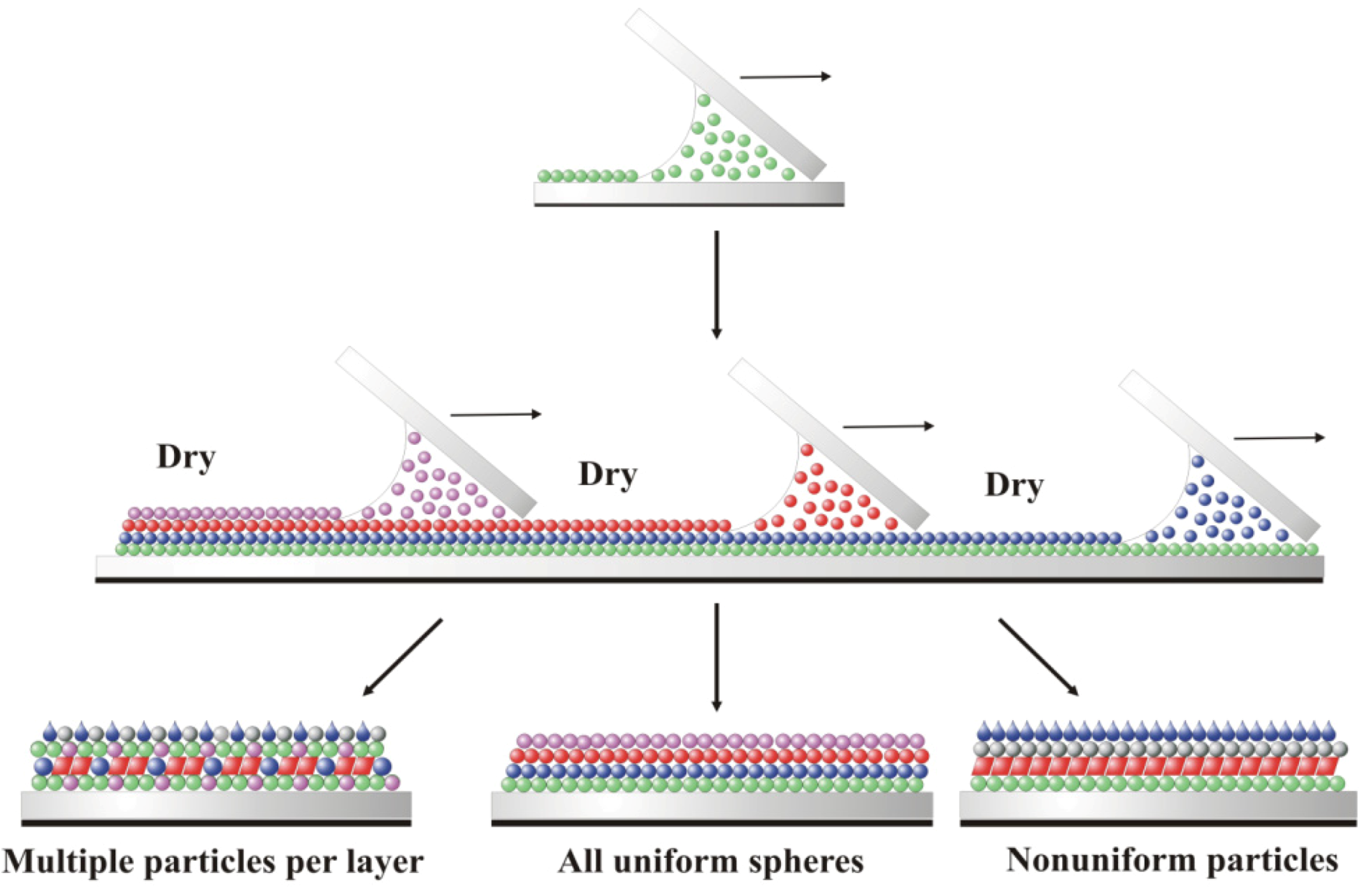
Schematic of coating microstructures that could be deposited using sequential convective assembly of particle monolayers to form multilayer, composite bioreactive devices. Each color represents a different type of particle or cell. Each new layer is deposited after the underlying layer has dried under controlled temperature and relative humidity conditions.
Figure 1.
Schematic of coating microstructures that could be deposited using sequential convective assembly of particle monolayers to form multilayer, composite bioreactive devices. Each color represents a different type of particle or cell. Each new layer is deposited after the underlying layer has dried under controlled temperature and relative humidity conditions.
The convective assembly combines fluid evaporation, particle transport via fluid flow, and associated meniscus motion to rapidly and controllably deposit ordered thin films on practically relevant coating surface area scales. The assembly process begins when the thickness of the evaporating fluid film becomes thinner than the diameter of the suspended particles. The menisci formed around these particles give rise to attractive capillary forces that pull adjacent particles together as the liquid evaporates, forming two-dimensional nuclei [
25,
26,
27]. A liquid flux from the suspension bulk to the substrate-air-liquid contact line at the drying front offsets fluid loss due to evaporation, resulting in particle transport to the drying front as adjacent particles aggregate and subsequent proliferation of the coating [
25,
26,
28]. A particle mass balance relates the coating growth rate,
vc, to the fluid evaporation rate and particle volume fraction:
where
β is an interaction parameter,
je is the evaporation rate,
l is the drying length,
φ is the volume fraction of the particles in suspension,
h is the height of the deposited colloidal crystal array, and
ε is the coating porosity [
27,
29]. The values of
β vary between 0 ≤
β ≤ 1 and depend on particle-particle and particle-substrate interactions. For suspensions with low volume fractions and electrostatically stable particles,
β → 1 [
28]. Once
vc is determined, the length of the thin film in which deposition occurs by convection can be calculated using a material flux balance:
where
vw is the deposition rate and equal to
vc at steady state, and
ci is the concentration of the bulk suspension at that particular time [
29].
Using an all-colloid system, Prevo and Velev reported a modified convective assembly technique that allows for rapid and controllable deposition of coatings from micro liter suspension volumes [
8]. 5–30 µL of coating suspension containing particles at high volume fraction (0.9%–35% w/v) is trapped between a horizontal substrate plate and an inclined coating knife plate. The inclined top plate is moved at a constant rate along the long axis of the bottom plate by a linear motor. This delivers and spreads the suspension from the meniscus into a thin film across the horizontal substrate, leading to the formation of a coating on the substrate by evaporative convective assembly [
9]. The number and type of deposited particle layers are readily adjusted by altering the suspension volume fraction and coating knife speed, allowing for precise control in particle packing and coating thickness [
8]. If the meniscus height is less than the particle diameter at the growth front, as in the case of faster knife speeds, the incoming particles form an open-packed structure [
28]. Conversely, for slower knife speeds, if the meniscus height is greater than the particle diameter, multilayer deposition occurs [
28].
Many methods for depositing colloidal arrays via convective assembly in thin films are variations of the convective assembly apparatus reported by Prevo and Velev that can be optimized by varying the basic process. Kleinert and Velev coupled the convective assembly mechanism with an electric field to obtain more rapid particle assembly, larger crystal domains, and reduced structural defects [
11]. Park and coworkers proposed a modified convective assembly technique that uses a dip-coating apparatus to modulate the meniscus thinning rate, allowing for the formation of well-ordered, multilayered single-component and binary colloidal crystals [
15]. Robinson
et al. later presented another variation that more rapidly deposits crystalline films than conventional convective assembly by altering the fluid evaporation rate through restricted movement of the meniscus along the top plate [
16]. However, while these variations offer greater control over the assembly process, the utility of convective particle or cell assembly in thin films on an industrial scale is restricted because the total coating surface area is limited by the amount of suspended particles delivered by the continuously depleted (batch) coating meniscus volume.
In order to evaluate methods to deposit large surface area composite coatings of polymer particles and live cell blends in uniform monolayers for future biocoating or biotechnology applications, we investigated a model colloid system to develop new methods for continuous convective assembly of thin films on the basis of controllable continuous delivery of particle suspensions to the meniscus. This method allows for steady-state coating deposition by constantly dispensing suspended uniformly charged particles (or charged particles + live cells) to the meniscus, resulting in colloidal array coatings with larger surface areas. We call this method Continuous Convective-Sedimentation Assembly (CCSA) to distinguish it from conventional batch deposition. Using monodispersed sulfated polystyrene microspheres, we investigate and report how particle concentration, fluid flow-path sonication, and suspension density influence the coating microstructure when the meniscus is constantly supplied with particles. We also examine how two configurations of the CCSA apparatus perform in this process: (1) topside CCSA, in which suspension flows through a capillary from a fluid reservoir to the front of the meniscus along the coating knife’s topside, and (2) underside CCSA, in which suspension flows into the meniscus from a fluid reservoir through a capillary fixed to the back of the knife. Finally, we compare batch and continuous convective assembly and discuss how the variation of meniscus volumes affects the coating microstructure by varying the number of particles available for deposition.
2. Results and Discussion
Although CCSA solves the limitations of earlier batch deposition strategies by continuously delivering suspended particles to the meniscus during coating fabrication, the technique lacks the detailed parameter characterization necessary to optimize coating appearance. Here we investigate multiple process and particle suspension parameters to identify the critical parameters responsible for rapid and controlled, continuous deposition of crystalline colloidal arrays, thus enabling control over coating thickness and structure.
2.1. Microsphere and Solvent Delivery Material Balances
Material and fluid balances of monodispersed sulfated polystyrene microspheres were calculated to identify particle and solvent losses in the CCSA apparatus that may disrupt the evaporative and convective fluxes that are responsible for coating propagation (see
Section 3.5 for the experimental protocol). The microsphere balance confirms that the delivery system does not inhibit particle delivery to the meniscus, despite losses through particle sedimentation in the delivery system and onto the coating knife of a suspension with 8% solids (
Table 1). However, the material balance is conservative in that it lacks a factor to account for the multilayered particle aggregation along the coating edges (parallel to the direction of deposition) which is a significant artifact of small surface area coating systems with a large edge/surface area ratio [
30]. Several investigators have suggested methods to reduce this artifact as well as meniscus-related edge effects [
30]. The particle balance assumes that the number of aggregated particles along the coating edges offsets the number of the particles in the thinner coating interior such that the total number of enumerated particles post-deposition would lead to a complete monolayer under optimal deposition conditions (no edge artifacts). This balance likely undercounts the total amount of particles in the coating, resulting in an estimate of only 2.9% of the particles delivered to the meniscus being deposited in these test coatings.
To evaluate the role of colloid particle sedimentation, the washed microspheres were blended with OptiPrep
TM in an 80:20 (v/v) ratio prior to deposition to reduce particle settling in the tubing. OptiPrep™ addition reduced the percent solids in the suspension to ~2%. Because OptiPrep
TM has a relatively high density of 1.32 g/mL compared to that of polystyrene latex (1.05 g/mL), the blended suspension has an appreciably higher density than the aqueous latex suspension, making the microspheres more buoyant leading to less particle sedimentation (
Table 1). This further decreased the percentage of particles delivered to the test coating to ~2.4%.
Table 1.
Microsphere counts before and after deposition of a pure microsphere suspension of 8% solids and an OptiPrepTM-enriched suspension containing ~2% solids.
Table 1.
Microsphere counts before and after deposition of a pure microsphere suspension of 8% solids and an OptiPrepTM-enriched suspension containing ~2% solids.
| | Pure Microsphere Suspension | OptiPrepTM + Microsphere Suspension |
|---|
| | Pre-Deposition | Post-Deposition | Pre-Deposition | Post-Deposition |
| Syringe | 4.2 × 10¹⁰ | 3.5 × 10⁹ | 5.5 × 10¹⁰ | 3.5 × 10⁹ |
| Coating Knife | 0 | 6.3 × 10⁷ | 0 | 6.3 × 10⁷ |
| Fitting | 0 | 0 | 0 | 4.1 × 10⁸ |
| Meniscus | 0 | 5.7 × 10⁹ | 0 | 1.1 × 10⁸ |
| Tubing | 0 | 6.8 × 10⁹ | 0 | 3.1 × 10⁷ |
| Coating | 0 | 1.1 × 10⁹ | 0 | 1.2 × 10⁹ |
| TOTAL | 4.2 × 10¹⁰ | 1.7 × 10¹⁰ | 5.5 × 10¹⁰ | 6.4 × 10⁹ |
The results indicate that approximately equal numbers of particles are deposited into the coating for both the pure and OptiPrepTM-enriched microsphere solutions (2.6% and 2.4%, respectively). Also, an almost identical number of particles remained in the syringe after deposition (~91.6%), for both suspensions, accounting for the difference between the particle count “pre” and “post-deposition. However, the percentage of microspheres remaining in the fittings, meniscus, and tubing post-deposition, relative to the total particle number in the syringe before deposition, is less for the OptiPrepTM blend compared to the pure microsphere suspension (1% versus 3%, respectively), suggesting that OptiPrepTM inclusion acts favorably to reduce particle sedimentation in the delivery system.
Separate balances were calculated for sonicated and non-sonicated trials to evaluate the effect of continuous piezo sonication of the fluid delivery system on the deposition process. The ambient relative humidity and temperature above the evaporating water were 60%–75% and 22–24 °C, respectively. The solvent material balance was corrected for water evaporation during the pumping period (see
experimental section and
Appendix A in supplemental information).
Fluid material balances generated by pumping fluid through the delivery system into a weighing dish (instead of the coating knife meniscus) confirmed that the modified coating method continuously delivers the coating suspension to the meniscus with minimal solvent loss, regardless of sonication. Sonication appears to decrease the volume of water pumped into the weighting dish—the average volumes in the dish after pumping are 0.52 ± 0.08 and 0.44 ± 0.02 mL when the fluid is stagnant and agitated, respectively. The evaporative loss calculations only account for relative humidity and temperature differences at the air-liquid interface, while they ignore the effects of the sound waves on the evaporation rate of the agitated fluid. However, although sonication affects solvent loss, any evaporative losses from both stagnant and agitated fluids are likely negligible during continuous convective-sedimentation assembly because the suspension is deposited onto the substrate in less than an hour whereas the water was pumped into the weigh dish for 16–25 h.
2.2. Coating Structure Dependence on Suspension Density
Coating structure can also be modified by using a microsphere suspension with a density-modified medium like iodixanol particles (OptiPrepTM). Modifying the suspension density allows increasing the buoyancy of the suspended particles and thus minimizes particle sedimentation onto the substrate.
To test this hypothesis, coatings were deposited from either pure microspheres in water (ρ
suspension = 1.05 g/mL) or an 80:20% (v/v) composite OptiPrep
TM-microsphere solution (ρ
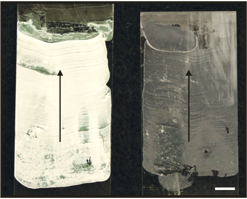
suspension = 1.27 g/mL) at an ambient chamber temperature of 26.5 ± 1.8 °C and relative humidity of 49.6% ± 1.3% using underside CCSA and a knife speed of 21.1 µm/s. Visual analysis of both coating macrostructures shows that OptiPrep
TM appears to minimize particle clumping across both the coating width and length, improving the overall uniformity (
Figure 2).
Figure 2.
Coatings deposited from 1.0 µm microspheres (left) and an 80% (v/v) composite blend of OptiPrepTM and 1.0 µm microspheres (right). Scale bar is 5 mm; arrows indicate direction of deposition.
Figure 2.
Coatings deposited from 1.0 µm microspheres (left) and an 80% (v/v) composite blend of OptiPrepTM and 1.0 µm microspheres (right). Scale bar is 5 mm; arrows indicate direction of deposition.
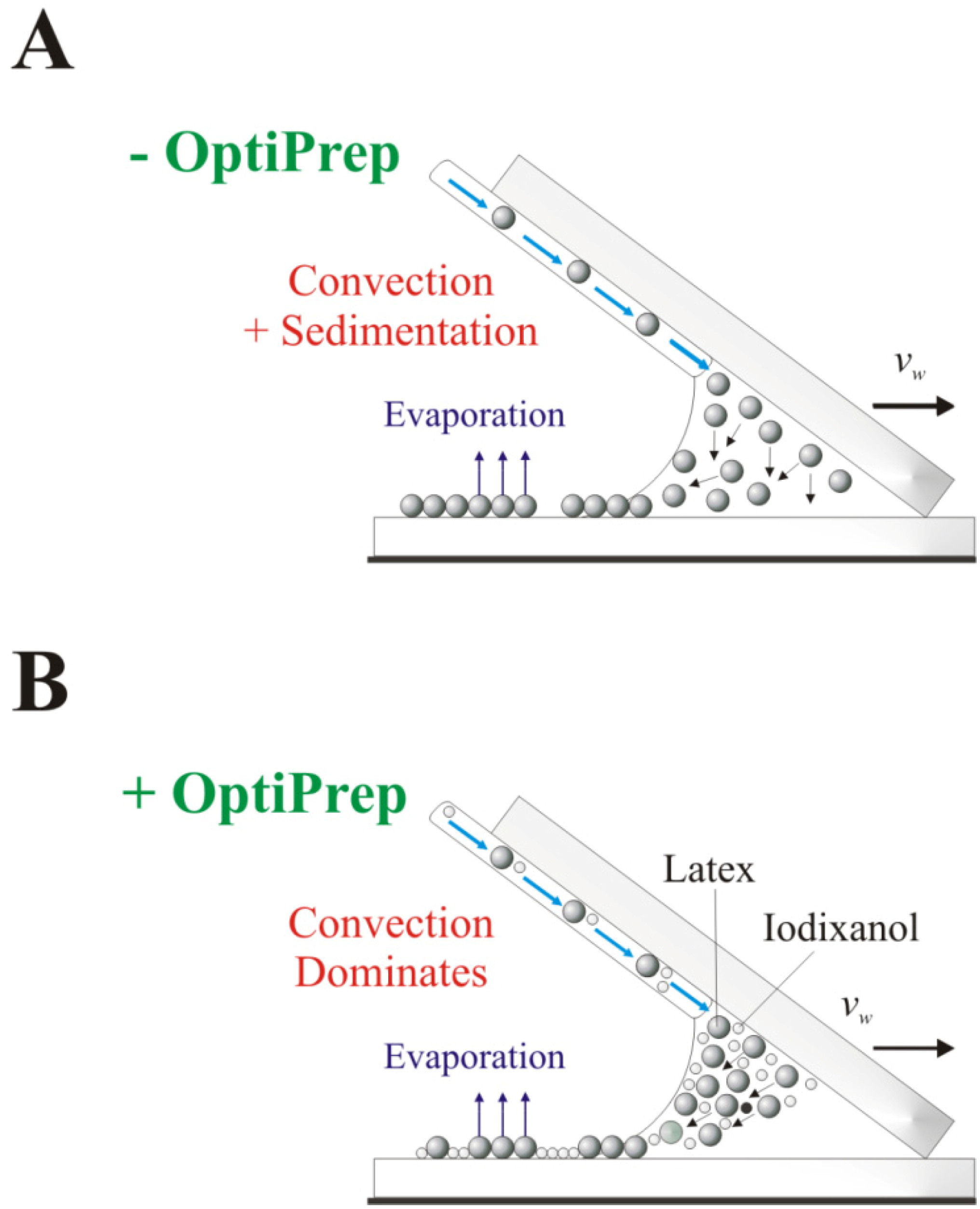
Blending the microsphere suspension with OptiPrep
TM changes the dynamics of the assembly process by introducing a transition between long-range and short-range particle ordering. Because the suspended microspheres are more buoyant in an OptiPrep
TM-enriched suspension, they are more likely to remain suspended in the meniscus throughout the deposition period (see
Figure 3). Thus, particles will remain at or near the meniscus surface and will be assimilated into the coating only after the thickness of the evaporating meniscus becomes smaller than the diameter of the suspended microspheres, leading to more uniform particle sedimentation onto the substrate surface.
Figure 3.
Schematic of the proposed variation in coating assembly when suspension fluid density is modified. (A) Aqueous particle suspension process. The particles disperse throughout the meniscus; (B) OptiPrepTM-medium with increased fluid density, altering the convective assembly mechanism by delaying particle incorporation into the coating.
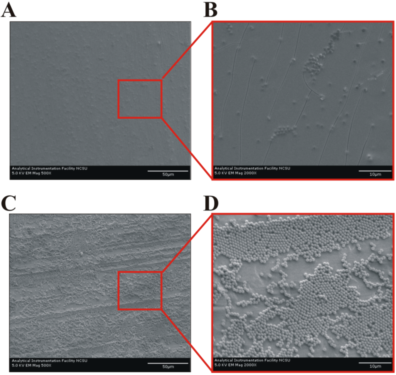
Overall, the suspension density modification appears to reduce the average coating thickness and produces a more uniform, though less structured, monolayer (
Figure 4). The observed film is affected by the high concentration (~80% (v/v)) of OptiPrep
TM necessary to make the solvent denser than the latex microspheres. The iodixanol particles formed during the drying coalesce into a continuous film that fills the void space created by the 1.0 µm microspheres during coating fabrication (
Figure 4B), leading to reduced striations across the coating’s surface and improved overall visual appearance. Thus, while OptiPrep
TM does not change microsphere and solvent delivery rate to the meniscus (see
Section 2.1), the iodixanol particles alter the coating’s structure by disrupting the convectively-assembled crystalline array.
Figure 4.
Microstructure of coatings deposited on aluminum foil. (A, B) 80% (v/v) composite OptiPrepTM + 1.0 µm microspheres and (C, D) pure 1.0 µm microspheres. Scale bars are 50 µm in (A, C), and 10 µm in (B, D). The ridges in (C) are an artifact that arises from the limitations of the experimental coating apparatus and the use of glass slides with non-rounded edges.
Although latex particles are an ideal model system for exploring parameter effects on coating microstructure, latex-only arrays offer limited commercial value because these coatings are only suited for applications that do not require reactive surfaces, thus eliminating any use in biotechnology applications. We have recently showed that deposition of thin latex polymer particle coatings is a critical precursor to the formation of 1–2 cell layer thick microbial coatings of live cells and latex polymer particles [
12]. These biocoatings offer the promise of improved nutrient diffusion to immobilized cells (by creating nanoporosity) and uniform illumination of the particles or cells (by reducing cell-cell shading), thus overcoming the mass transfer and optical limitations of thicker coating systems. This finding also makes convective-sedimentation assembly suitable for biotechnology applications, thereby expanding the method’s utility.
2.3. Coating Structure Dependence on Suspension Sonication during Deposition
Particle sedimentation strongly affects both coating uniformity and the convective assembly process. When sedimentation dominates, most suspended microspheres sediment straight down onto the substrate outside of the drying region [
9]. This complicates the deposition of highly uniform coatings by continuously reducing the number of particles transported to the drying front over the deposition period. Sonication was evaluated as means to suppress particle sedimentation during deposition, since sonic standing waves have been used successfully in noncontact manipulation of suspended particles [
31,
32,
33,
34,
35]. Coatings were deposited using a glass substrate and either a stationary or sonicated continuous delivery system. We observed that changes in vibration frequency up to 1 kHz and piezo positioning underneath the substrate edge had no effect on the coating structure. Sonicating the substrate (rather than the suspension) did not appreciably change the coating structure. All coatings were deposited using the same knife and delivery system (syringe, fitting, and tubing) to ensure that any deviations in the dried coating appearance are a sonication result. The delivery system was positioned approximately 3 mm from the knife’s leading edge to eliminate the risk of the tubing end affecting the coating uniformity. Coatings were deposited at a chamber temperature of 25.9 ± 2.0 °C and relative humidity of 51.6% ± 3.4% using a knife speed of 21.1 µm/s.
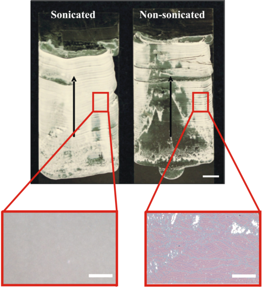
The effect of piezoelectric fluid agitation in the delivery system during deposition is shown in
Figure 5. Although the images and micrographs show regions of dense particle packing in both coatings, the sonicated delivery system has better coating uniformity than the non-sonicated system. Unlike the highly uniform sonicated coating, the coating delivered without piezo vibration of the delivery path ranges from a near monolayer to a submonolayer (high void space) and multilayer particle clusters (see micrographs in
Figure 5). Also, coatings deposited with the vibrated fluid-flow delivery system show a higher degree of surface coverage (or lower void space) on both the macroscopic and microscopic levels than comparable coatings deposited with the stationary delivery system. In summary, ultrasound sonication of the suspension delivery system improves coating uniformity.
Figure 5.
Structure of coatings deposited from a 1.0 µm microsphere suspension when the tubing of the delivery system is vibrated at 400 Hz (left) or without vibration (right). The non-sonicated fluid delivery system coating has uneven particle distribution along its length and width whereas the vibrated coating is highly uniform with no pronounced particle aggregation along the substrate edges. Scale bars for coating images and micrographs are 5 mm and 50 µm, respectively; arrows indicate direction of deposition.
2.4. Coating Microstructure Dependence on Suspension Particle Concentration
Coatings from suspensions concentrated to 8% (w/v), 12% or 16% were deposited to determine if the number of particles delivered to the drying front affects the coating void space. The coatings were deposited at 70% relative humidity and a knife speed of 190 µm/s as this combination minimizes the particle piling along the substrate edges noticed during the evaluation of the microsphere and solvent delivery material balances. The parameter values were chosen within the relative humidity and deposition speed ranges of 35% to 70% and 21–190 µm/s, respectively. Relative humidity and temperature data varied within 77.3% ± 2.3% and 29.1 ± 1.8 °C, respectively. Two surface topography profiles of sections of the coating width were obtained for each coating using a random selection scheme to remove sampling bias. Profiles were grouped by sample number.
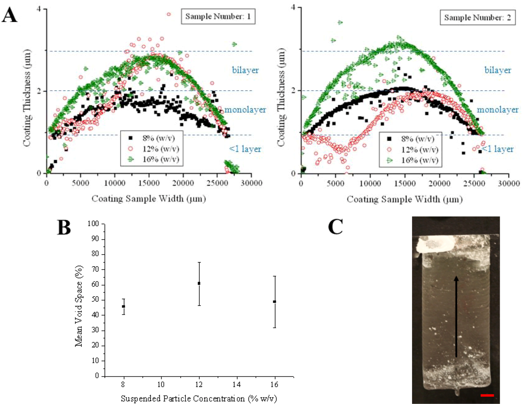
The suspended particle concentration strongly affects coating thickness (of 1 to 3 particle layers), but has no appreciable effect on void space (
Figure 6). The 8%, 12%, and 16% (w/v) suspensions deposit coatings with similar void spaces (
Figure 6B). However, the 16% suspension yields coatings that are ~1 particle thicker than coatings deposited from the 8% and the 12% suspensions (
Figure 6A). The large variation in the scans of coating sections, especially for the film deposited from the 12% suspension, shows the coatings are not perfect monolayers and that coating thickness varies by more than one particle diameter with particle concentration. Relatively high fraction of high void spaces (>50% on average) was observed for all coatings. A strong correlation between suspended particle concentration and coating void space cannot be identified due to the overlapping error bars (
Figure 6B). However, higher suspended particle concentrations will likely result in overall thicker coatings (>3 particles thick) by increasing the height of the liquid film, enabling influent particles or even particle aggregates to flow over and settle atop other deposited particles during the assembly process [
12].
Figure 6.
Effect of suspended particle concentration on coating (A) thickness and (B) void space for regions of coatings deposited from 8%, 12%, and 16% suspensions of 1.0 µm sulfated polystyrene polymer particles. Thickness profiles determined by profilometry are grouped by sample number to simplify data interpretation. (C) Coating deposited at 16% solids showing minimized particle aggregation along coating edges. Arrow indicates direction of deposition; scale bar is 5.0 µm.
2.5. Evaluation of Suspension Deposition Mode
To understand how the mode of suspension delivery affects the microstructure of coatings deposited using CCSA, coatings were deposited in triplicate using either the topside or underside CCSA modes at 26.2 ± 2.3 °C and 45.9% ± 6.2% relative humidity. All coatings were deposited using a knife speed and suspension flow rate of 21.1 µm/s and 1.0 µL/min, respectively, from an initial meniscus volume of 24.0 µL. Each coating was analyzed for changes in meniscus volume, normalized by the calculated volume at 0 mm, and average void space, as reported in
Figure 7. Micrographs were collected at three 7.5 mm intervals across the coating length, starting 5 mm from the coating’s leading edge, at positions located 15 and 35 mm from the coating’s side edge (see sampling scheme in
Figure 7B). This protocol allowed for comparison of the structural uniformity for multiple coatings.
To estimate meniscus volume, still images of the meniscus profile were collected using a wireless digital camera and analyzed with image processing software to determine the meniscus height and length in each image. The volume of the entrained liquid was calculated by approximating the meniscus shape as a triangle with a curved edge (see
Experimental section for detailed product information and explanation of calculations). The effect of meniscus volume on coating structure was investigated because this volume dictates both the meniscus shape and total number of suspended particles assembled into the final coating, whether by convective assembly or particle sedimentation.
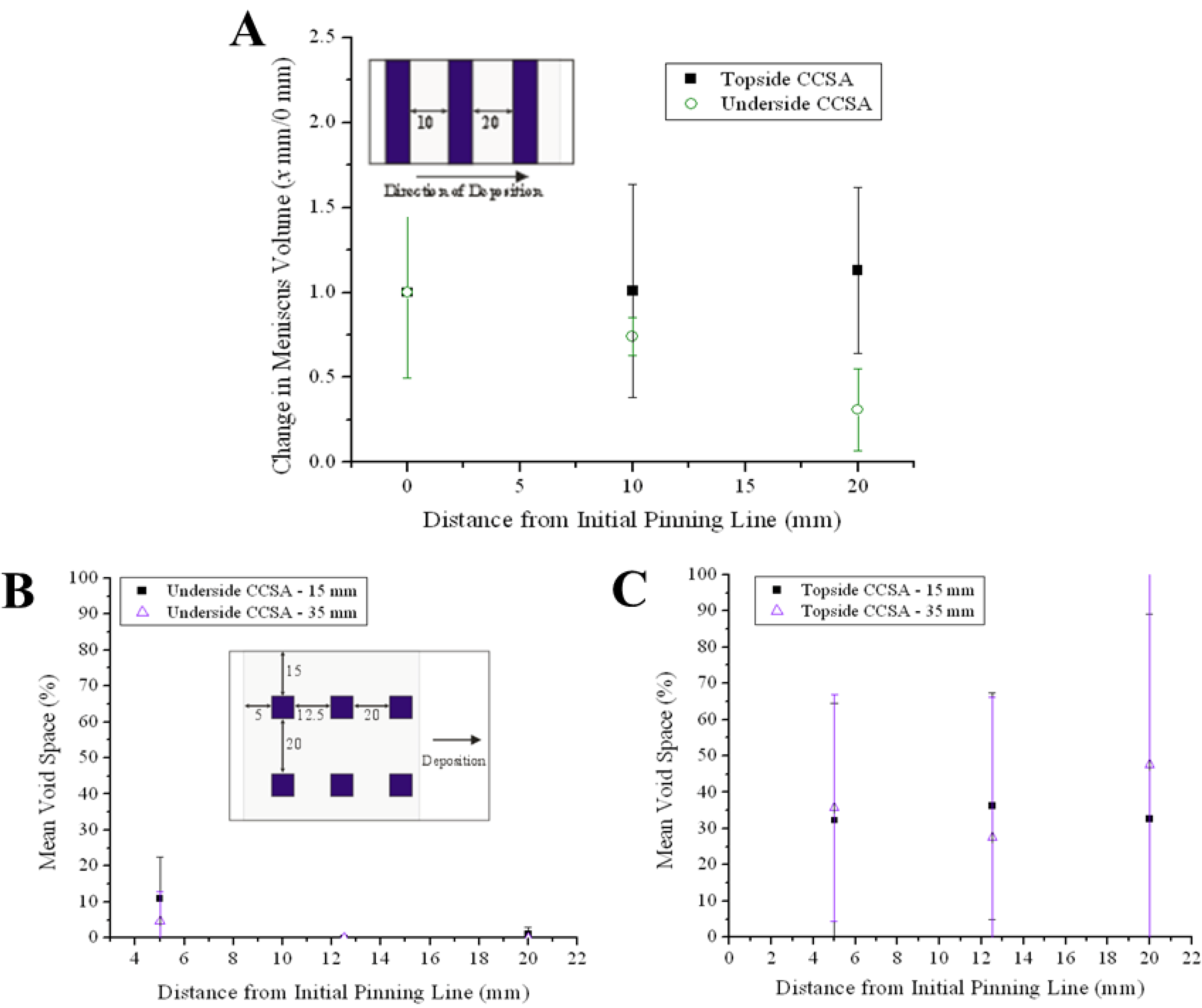
Analysis of
Figure 7 shows that the coatings deposited via topside and underside CCSA are dissimilar. The coatings deposited via topside CCSA have a comparatively large variation in mean void space but a relatively constant meniscus volume whereas underside coatings exhibit a lower variation in mean void space. The continuously decreasing meniscus volume observed by underside delivery indicates that the delivery rate was too slow to maintain a constant volume. The overall lower void space suggests that more particles are transported to the drying region (and incorporated into the propagating coating) in underside CCSA Conversely, the near constant meniscus volume and high, variable voids in the topside coatings suggest less particles reach the drying region in topside CCSA. This is possible if circulating flow patterns exist in the meniscus [
9]. Because the topside CCSA deposition mode and the batch deposition deliver suspension to the front of the meniscus opposite the drying region, it is likely that an eddy also exists in the meniscus during topside CCSA deposition. As such, rather than flowing directly to the drying region at the rear of the interface, particles may become entrapped in the circulating eddy and only move to the drying region when the eddy becomes saturated with particles, a dynamic instability leading to the formation of coatings with variable voids.
Figure 7.
Variation in (A) meniscus volume and (B) mean void space over coating length during topside and underside CCSA deposition. Insets show sampling scheme for characterizing each parameter; all marked distances are in mm from the beginning of the coating.
Figure 7.
Variation in (A) meniscus volume and (B) mean void space over coating length during topside and underside CCSA deposition. Insets show sampling scheme for characterizing each parameter; all marked distances are in mm from the beginning of the coating.
2.6. Evaluation of the Effect of Suspension Delivery Rate on Meniscus Volume
Although comparison of the topside and underside CCSA deposition confirms the deposition mode affects both meniscus volume and coating microstructure, this analysis failed to explain the effect of the delivery rate itself on the meniscus volume. To understand this relationship, coatings were deposited using a hybridized form of the conventional batch and underside CCSA deposition modes—the meniscus was created by manually injecting an aliquot of coating suspension between the substrate and coating knife (batch CSA) and continuously replenished with suspension at a constant flow rate (CCSA)—and suspension delivery rates of 0.0 (to simulate batch deposition), 1.0, 2.0, 4.0, and 6.0 µL/min. Elimination of the coating edge effects observed at low knife speeds and relative humidity was not attempted because the study’s purpose was to clarify how suspension flow rate affects meniscus volume and coating microstructure. All coatings were analyzed for variations in coating macrostructure and visual appearance.
The micrographs in
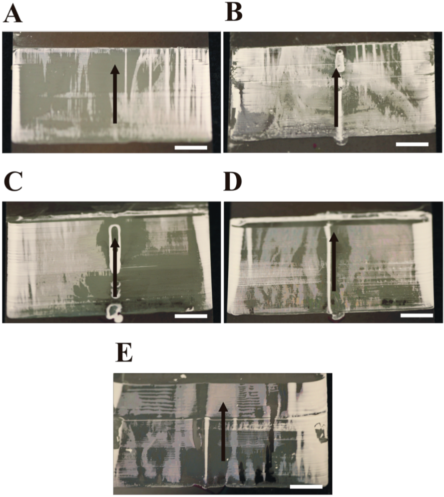
Figure 8, suggest that, for a given convective assembly deposition mode and initial meniscus volume, coating quality is independent of suspension delivery rate, at least for the experimental coating apparatus employed in this study. No coating exhibits complete macroscopic uniformity or monolayer thinness—all coatings contain randomly-located thick (intense white) and thin (dull white) regions. For all coatings, the thick zone covers at least 50% of the coated surface area. Also, all non-zero flow rates create visible particle accumulation near the tubing outlet across the entire coating length (in the direction of deposition), an observation that gives credence to the existence of an eddy in the meniscus. Finally, both the batch mode (0 µL/min) and 1.0 µL/min flow rates exhibit a similar, decreasing meniscus volume across the coating length. The higher flow rates exhibit variable—both increasing and decreasing—meniscus volume across the coating length when utilizing the optical image method for estimating meniscus volume (data not shown).
Figure 8.
Structure of coatings deposited from a 1.0 µm microsphere suspension at a volumetric delivery rate of (A) 0.0 (batch), (B) 1.0, (C) 2.0, (D) 4.0, and (E) 6.0 µL/min during underside CCSA deposition. Scale bars for coating images are 5 mm; arrows indicate direction of deposition. Observed ridges are an artifact that arises from the limitations of the experimental coating apparatus and the use of glass slides with non-rounded edges as the coating knife.
3. Experimental Section
3.1. Preparation of Coating Substrates and Deposition Plates
Fisherbrand 75 × 25 and 75 × 50 mm glass microscope slides (Fisher Scientific) and Dow Corning 75 × 50 mm glass microscope slides (Fisher Scientific) were pretreated as previously described [
9] using NoChromix solution to remove adsorbed organic molecules and deprotonate surface hydroxyl groups (Godax Laboratories, Cabin John, MD, USA). All pretreated slides were stored in separate 100 × 100 mm Fisherbrand Petri dishes (Fisher Scientific) until used in the CCSA deposition device. In order to have a conductive substrate for SEM imaging of coating microstructure, 75 × 25 mm strips of aluminum foil (Handi-foil of America, Wheeling, IL, USA) were rinsed with 70% (v/v) ethyl alcohol, gently wiped with a KimWipe (Kimberly-Clark, Chantilly, VA, USA) to remove surface contaminants, and dried at the ambient temperature and relative humidity to evaporate any residual alcohol. All foil strips were flattened using an Orcon smooth action roller (Tools for Floors, Waverly, NY, USA) prior to the alcohol rinse.
3.2. Preparation of Coating Suspensions
Sulfate latex microspheres (0.99 ± 0.014 µm) (Interfacial Dynamics Corporation, Eugene, OR, USA) were washed once with deionized water obtained from a RiOs 16 reverse-osmosis water purification system (Millipore Corporation, Bedford, MA, USA) to remove residual surfactants and electrolytes. The washed microsphere suspensions were subsequently concentrated to 8%, 12%, or 16% solids using a Fisher Marathon micro A microcentrifuge (3630 RPM for 5 min) for suspensions less than 1000 µL and using a Beckman TJ-6 bench-model centrifuge (3000 RPM for 5 min) for suspensions over 1000 µL. All suspensions were sonicated gently in an ultrasonic cleaner (Branson Ultrasonics Corporation, Danbury, CT, USA) to reduce particle aggregation before deposition.
Several washed microsphere suspensions were mixed with OptiPrepTM solution (Axis-Shield, Oslo, Norway) to evaluate the role of solution density in convective assembly and coating uniformity. OptiPrepTM is a low viscosity, sterile solution of 60% iodixanol in water with a density of 1.32 g/mL. All hybrid coating suspensions were blended using a Vortex-Genie mixer (Fisher Scientific) to promote solution homogeneity before deposition.
3.3. Deposition of Coatings by Continuous Convective-Sedimentation Assembly
All coatings were deposited using the convective assembly method described previously [
8] with an added continuous delivery system that feeds the coating suspension to the meniscus. We examine how both topside CCSA or suspension flow to the meniscus front along the knife’s topside and underside CCSA or fluid flow to the meniscus rear along the knife’s underside can deposit larger surface area polymer particle arrays by continuously delivering particles to the coating meniscus. The delivery system was attached to the deposition plate or coating knife and consists of a 1 mL NORM-JECT syringe (4.726 mm ID) (Henke-Sass, Wolf GmbH, Dudley, MA, USA) coupled to 16–18 cm of 0.022 × 0.042 in PTFE microbore tubing (Cole-Parmer, Vernon Hills, IL, USA) through a 3/32 in hose barb to female luer adapter. The tubing was bonded to the adapter’s hose barb with Dow-Corning 732 Multi-Purpose Sealant (Midland, MI, USA) or Dow-Corning Fast Tack 3165 RTV Adhesive Sealant to minimize fluid loss during deposition.
A freshly cleaned coating knife and substrate were attached to the deposition device after the delivery system was connected to the syringe and to the knife (
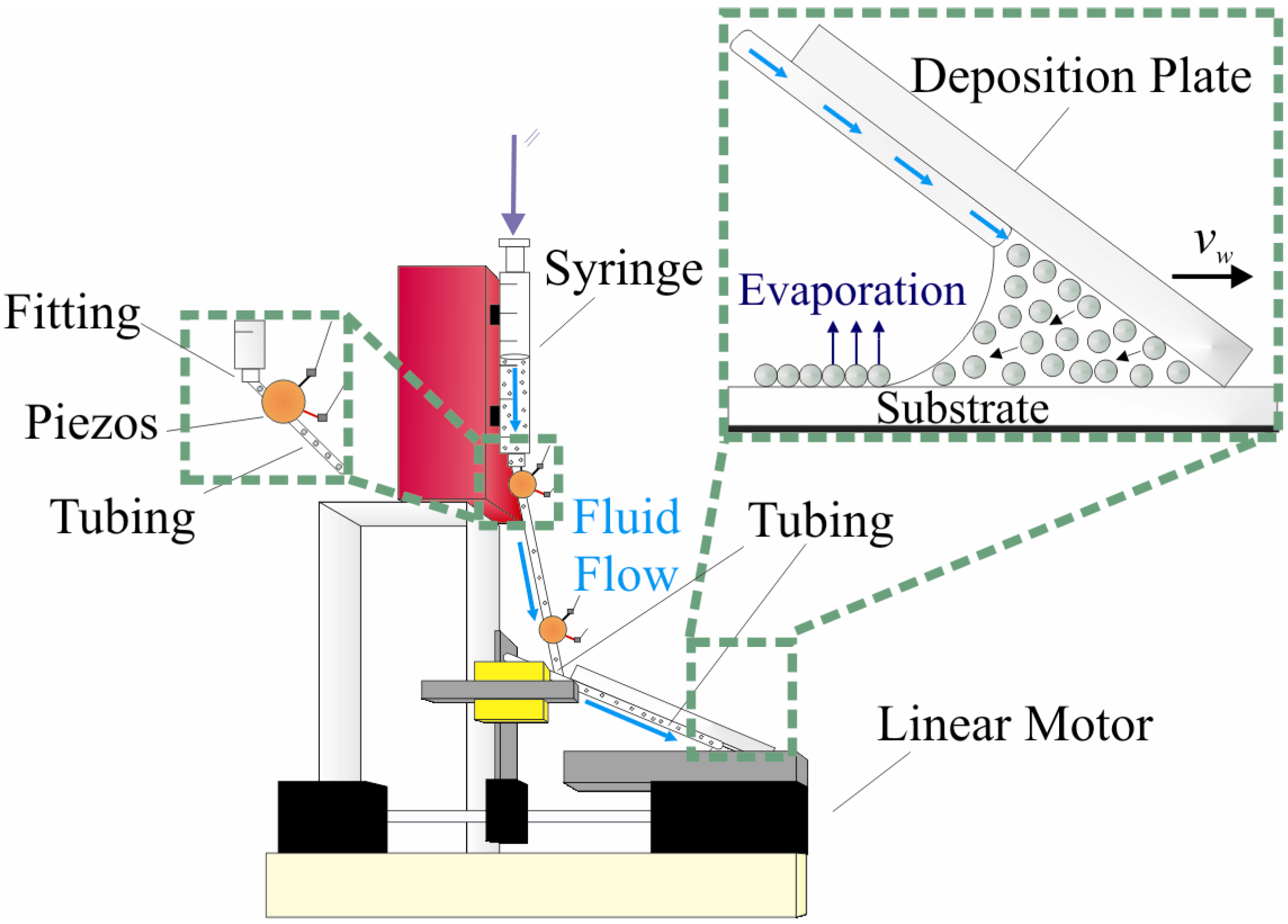
Figure 9). The system outlet was placed 1–3.5 mm away from the knife’s edge and 12.5 mm along its length to ensure uniform meniscus formation along the entire length of the knife. Positioning the outlet less than 2 mm from the knife’s edge prevents it from contacting the substrate. Suspension aliquots ranging from 500 to 1000 µL were pumped from the fluid reservoir to the back of the meniscus along the knife’s underside using a New Era NE-1800 syringe pump (Wantagh, NY, USA). The pump was operated at a priming rate of 100.5 µL/min to rapidly fill the wedge between the substrate and knife and then reduced to a standard rate of 0.5 µL/min after the meniscus covered the tubing outlet on the knife’s underside. The meniscus was filled to the tubing outlet to maximize effluent particle delivery and minimize aggregation on the knife’s underside around the tubing outlet. The linear motor pushing the coating knife was operated at a speed between 21 and 190 µm/s, while the suspension was deposited onto the substrate in 10–60 min.
The priming and standard delivery rates were selected by calculating the area of the entrained liquid from a set of equations describing the meniscus shape [
9] and calculating the pump flow rate that equilibrates the evaporative flux in the meniscus and the suspension delivery rate. The optical (and reported) monolayer deposition rate was determined by systematically varying the suspension feed rate around the calculated value to identify the rate that deposits the most macroscopically uniform coatings (data not shown).
For topside continuous convective-sedimentation assembly, the delivery system outlet was connected to the knife’s topside, enabling fluid flow from the fluid reservoir to the front of the meniscus along the topside. This configuration hybridizes the inherent advantages of continuous and batch convective assembly—delivering the suspension into the front of the meniscus through the gap between the substrate and knife decreases the required meniscus volume, enabling the use of smaller suspension volumes (a benefit of batch convective assembly) while still constantly renewing the meniscus (a benefit of CCSA). The system outlet was placed no more than 1 mm ahead of the knife’s edge to ensure uniform meniscus formation along the entire length of the knife. Although this results in fluid flow directly onto the substrate surface, the suspension is pulled into the meniscus before the suspended particles can settle onto the surface, thus eliminating unwanted coating formation in front of the knife. Suspension aliquots ranging from 200 to 1000 µL were pumped from the fluid reservoir to the gap between the substrate and knife at a constant rate, enabling coating formation in 10–30 min. All other experimental aspects were the same as in the underside continuous-sedimentation convective assembly configuration.
Figure 9.
Schematic of the continuous convective assembly coating apparatus. The fluid delivery system pumps the suspension from the fluid reservoir (syringe) to the interface between the deposition plate and substrate. Underside delivery system shown.
Figure 9.
Schematic of the continuous convective assembly coating apparatus. The fluid delivery system pumps the suspension from the fluid reservoir (syringe) to the interface between the deposition plate and substrate. Underside delivery system shown.
All CCSA coatings were deposited inside a Model 510 Benchtop Humidity and Temperature Controlled Environmental Chamber (Electro-Tech Systems, Inc., Glenside, PA, USA) at a chamber temperature of 20–30 °C and relative humidity of 40%–75%. The relative humidity was maintained with an ultrasonic humidification system (Model 5462 Electro-Tech Systems, Inc.) filled with deionized water. Both the chamber temperature and relative humidity were monitored with a calibrated probe (TM125 Dickson Addison, IL, USA). The syringe pump, tubing, and deposition device were placed inside a topless encasement made from rigid polypropylene sheets (Wilson Jones, Lincolnshire, IL, USA) to prevent the circulating air inside the chamber from disrupting solvent evaporation and associated particle transport during the assembly process.
CCSA uses larger volumes of coating suspension than other convective assembly techniques so Taylor dispersion and particle settling in the suspension delivery system may occur, leading to uneven particle delivery to the meniscus and associated irregularities in coating thickness and particle packing. The apparatus was modified to minimize particle sedimentation by 1) orienting the coating reservoir vertically, ensuring all particle sedimentation collinear with the flow to the outlet and 2) the flow-path tubing was continuously vibrated at 400 Hz using two 20 mm buzzer piezoelectric elements (Digi-Key Corporation, Thief River Falls, MN, USA) clipped to the delivery system and coupled to a GW Instek GFG-8210 function generator (Good Will Instrument Company, Chino, CA, USA), ensuring that particles were transported to the meniscus rather than settled onto the tubing walls. Many coatings in this study have thick, amorphous particle aggregates along their widths (coating edges perpendicular to the direction of deposition)—these regions are artifacts of the CCSA process that form where the meniscus dries on top of the assembled coating, leading to random, uncontrolled particle coalescence and disruption of the convectively-assembled coating. These edge artifacts can be reduced by additional refinements to the deposition method, such as draining the meniscus at the end of the deposition period.
To reduce variations in coating appearance associated with the knife’s surface roughness or extent of pretreatment, the same knife and delivery system were used to deposit all coatings in each series whenever possible. The knife was dried with a KimWipe and then rinsed with 70% (v/v) EtOH between depositions to remove any residual coating suspension and other debris from the coating edge.
3.4. Coating Characterization
All coatings were imaged by digital and optical microscopy for structural analysis. High resolution images were captured with a Canon EOS 5D Mark II SLR digital camera equipped with an EF (Electro-Focusing) 100 mm Macro lens. High magnification micrographs were taken with an Olympus BX61 microscope equipped with an Olympus DP70 CCD camera and 5× to 50× objectives. All micrographs were analyzed with Adobe Photoshop software to determine the fraction of the substrate surface that was covered with coating. To analyze the microstructure homogeneity within an individual coating, images were collected at three equally spaced sampling points across the coating width at 15 and 35 mm from the initial contact line. To compare the microstructure homogeneity of multiple coatings, images were collected using a double lattice selection scheme and a 4 × 4 square frame, as described [
36]. All squares were imaged in ten randomly-selected locations with a 20× objective, yielding a sample size for each square that describes almost 25% of that square. The calculation for the overall variation of the double lattice is also described [
36], where
r and
L are defined as two and four, respectively.
Random strips of pure suspension (OptiPrepTM or 1.0 µm microspheres at 8% solids) and an 80% (v/v) blend of OptiPrepTM-1.0 µm microsphere blend coated onto aluminum foil were selected for structural analysis. Dried coatings were imaged by scanning electron microscopy for structural analysis at the Analytical Imaging Facility at North Carolina State University using a Hitachi 3200-N Variable Pressure SEM equipped with a 4Pi Isis EDS system for digital image acquisition and elemental analysis. All coatings were observed in two or more randomized locations using a 5kV accelerating voltage. Each location was imaged multiple times using sequential magnifications ranging from 30× to 2000× to characterize surface structure. To increase sample conductivity (and micrograph quality), all samples were sputter coated with a thin layer of gold in a mild vacuum (~100 mTorr of argon gas pressure and 600 V accelerating voltage) prior to imaging.
Surface topography profiles to determine coating thickness were recorded using a Dektak D150 surface profilometer (Dektak D150, Veeco, Plainview, NJ, USA) coupled with the Dektak v9 software package. Standard scans were taken across the full coating width in random locations using a 12.5 µm radius stylus tip with 0.01–0.1 µm resolution and a 1.0 mg stylus force. Profiles were recorded in duplicate for each coating.
3.5. Evaluation of Microsphere and Solvent Material Balances
Particle and solvent material balances over the delivery system were used to identify the role of particle and solvent transport during deposition. The microsphere balance was quantified by calculating particle numbers for the meniscus, the coating knife and substrate, and each component of the delivery system after deposition. Fluid fractions from the coating meniscus and from the delivery system’s syringe, adapter, and tubing were characterized using flow cytometry. The particle surface densities for the coated regions of the knife and substrate were estimated by dividing each region by the area of an individual microsphere. All particle counts were performed using a Becton-Dickinson FACSCalibur flow cytometer (Franklin Lakes, NJ, USA) coupled with BD Cell Quest Pro software and calibrated using a mixture of 3.0–3.4 μm Rainbow Calibration Particles (Spherotech, Inc., Lake Forest, IL, USA). All fractions were first diluted to 100 μL with phosphate buffered saline (PBS) solution and then mixed with 100 μL of Rainbow Calibration Particles solution. Fluid fractions for both pure microsphere and microsphere-OptiPrepTM hybrid coating suspensions were collected and counted.
The solvent balance was evaluated by passing 500–1000 μL of deionized water through the delivery system for 16–25 h using a syringe pump (New Era NE-1800). The pump was operated at a priming rate of 100.5 µL·min−1 and then reduced to 0.5 µL·min−1 after suspension droplets freely flowed through the delivery system. The water was collected in an aluminum weigh dish (Fisher Scientific) covered with transparent plastic film to minimize water evaporation. The covered dish and a calibrated probe (TM125 Dickson) weighted before and after the pumping period. The delivery system was replaced with a Cadence Science 21G × 6 in standard hub, deflected point needle (Cadence, Inc., Staunton, VA, USA) to minimize fluid loss to the delivery system’s adapter piece [data not shown], improving the accuracy of the water balance. The water was continuously sonicated during the pumping period by vibrating two 20 mm Digi-Key buzzer piezo elements at 400 Hz using a GW Instek GFG-8210 function generator against the needle. Duplicate solvent balances were calculated for two flow conditions—agitated and static fluids—to isolate the effect of continuous sonication on solvent evaporation rate.
3.6. Meniscus Volume Characterization
Coating uniformity depends on the meniscus shape at the drying front [
30,
37] and on the total number of suspended particles in the meniscus [
8]. As we recently demonstrated how both substrate wettability and coating suspension composition control coating length and surface coverage, we did not report here the effect of meniscus volume on coating uniformity [
12]. We investigate the effect of meniscus volume on coating structure, analyzed as coating thickness, macroscopic appearance, and microscopic void space. To estimate the meniscus volume, still images of the meniscus from the side were collected using a Seeker 400 Series Wireless CameraScope Inspection System (Davis Instruments, Vernon Hills, IL, USA) equipped with a removable LCD display and interchangeable 9 and 12 mm diameter camera tipped probes. To quantify the meniscus volume, each image was analyzed with an image processing program (ImageJ, available to the public at [
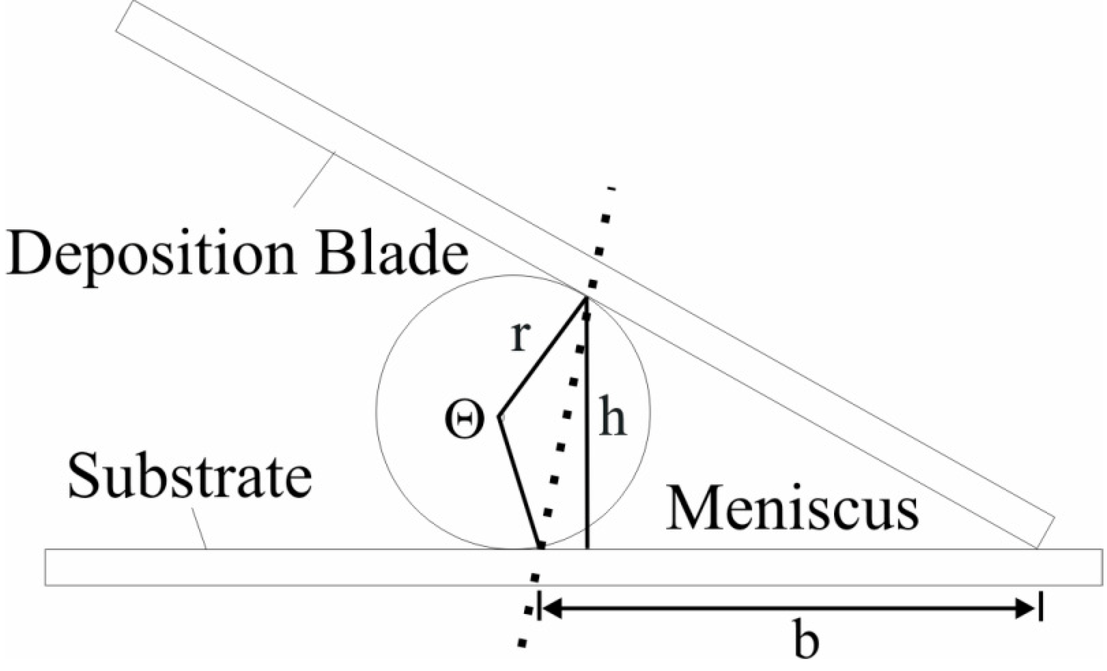
38]) to determine the meniscus height and length in that image. The volume of the entrained liquid was calculated by approximating the meniscus shape as a triangle with a curved edge (
Figure 10).
Figure 10.
Schematic of meniscus shape geometry used in the volume estimations.
Figure 10.
Schematic of meniscus shape geometry used in the volume estimations.
The volume is calculated as the product of the net area and the width of the deposition blade:
where
W is the knife width,
b and
h are the base and height of the triangle, respectively, and
θ is the central angle of the circle segment, and
r is the radius of the circle in which the segment is a part.
To account for aberrations in the imaging system and method, menisci with known volumes, namely 10.0, 25.0, 35.0, and 50.0 µL, were deposited via batch convective assembly in triplicate and imaged. All images were analyzed using Equation (3) and subsequently averaged to obtain a mean estimated volume for each known volume. A calibration curve of the actual meniscus volumes versus the mean measured ones was constructed (R2 value of 0.998).
3.7. Evaluation of the Effect of Suspension Deposition Mode and Rate on Meniscus Volume
Washed, 1.0 µm white sulfate-functionalized latex microspheres were first concentrated to 16% solids and then deposited using hybridized forms of the conventional batch and topside CCSA or underside CCSA modes to study the effect of suspension deposition mode and delivery rate on meniscus volume and coating morphology. The deposition mode study used both the topside and underside CCSA configurations whereas the delivery rate study used only the underside CCSA mode. All coatings used the same initial meniscus volume of 24.0 µL and a knife speed of 21.1 µm/s. Any resulting changes in the meniscus volume or coating structure over the coating length can be attributed to the deposition mode or delivery rate. A suspension delivery rate of 1.0 µL/min was used for the deposition mode study whereas the delivery rate was varied between 0 (batch), 1.0, 2.0, 4.0, and 6.0 µL/min for the delivery rate study. For each coating, the meniscus was photographed at 0, 10, and 20 mm from the initial pinning (or contact) line using the side camera, and the initial pinning line was formed ahead of the 0 mm mark to ensure the meniscus was fully developed prior to imaging. To understand the effect of deposition mode on coating structure, coating micrographs were taken at 5, 12.5, and 20 mm from the initial pinning line along two separate axes, located at 15 and 35 mm along the coating width, using an Olympus BX61 optical microscope coupled with a 50× objective.
4. Conclusions
The results demonstrate how continuous convective assembly can be optimized for continuous deposition of polymer particle coatings with larger surface areas than previously described. The modified coating apparatus continuously delivers polymer microsphere suspensions to the meniscus via inline injection. We investigated how two variations of the CCSA apparatus perform in generating larger surface area polymer particle arrays between 1 and 3 particle diameters thick by continuously delivering particles to the drying front for coating assembly. However, changing the suspension delivery mode (topside versus underside CCSA) yields disparate meniscus volumes and uneven particle delivery to the drying front, which alters the coating microstructure by varying the total number of particles available for deposition. For any of these convective assembly deposition modes and the same initial meniscus volume, coating quality was found to be independent of suspension delivery rate and meniscus volume during coating fabrication, at least for the coating apparatus employed in this study.
We also investigated the effect of suspended particle concentration, fluid sonication, and density modification on the microstructure of coatings deposited from continuously supplied 1.0 µm microsphere suspensions. Fluid density modification using iodixanol particles and fluid sonication affect particle sedimentation and distribution in the coating growth front whereas the suspended particle concentration affects coating thickness, but has almost no effect on void space. Suspension density modification appears to reduce the average coating thickness and produces a more uniform, though less structured, monolayer, while sonication of the fluid-flow delivery system yields coatings with a higher degree of surface coverage (or lower void space) on both the macroscopic and microscopic levels than comparable coatings deposited with the stationary delivery system. Conversely, suspended particle concentration has no appreciable effect on void space, but does strongly affect coating thickness (of 1 to 3 particle layers). This study did not examine the combined effect(s) of these parameters because our goal was to understand each parameter’s individual role in controlling coating microstructure. The observed trends suggest that the uniformity of any particle, or even coatings of live cells can be improved through fluid sonication and suspension fluid density modifiers. Future practical implementation of the CCSA could examine the combined effect of these parameters on coating microstructure and use such a combination in the deposition of large uniform coatings.
While no CCSA coating mode exhibits macroscopic uniformity or 100% monolayer coating, this study demonstrates that the CCSA technique deposits coatings whose homogeneity and structure are comparable to traditional batch convectively-assembled coatings with decreasing meniscus volume. Noncrystalline or non-uniform CCSA coatings, like batch-assembled arrays, are well suited for numerous applications, including electrical circuits [
17], chemical sensors [
20,
21], and porous membranes [
3,
22,
23,
24].
CCSA coatings hold the promise of generating longer, larger surface areas than batch-fed coatings, giving convective industrial relevance. The current study identifies and interprets the role of the key parameters that control coating appearance (microstructure and thickness) when the meniscus is continuously supplied, laying the groundwork for future studies on coating appearance optimization. Overall, CCSA may be a promising method for generating monolayer or very thin coatings of polymer particles and live cells for numerous biotechnology applications where a highly bioreactive surface is required. It could be extended to engineer multi-layer coatings of particle-bound enzymes or combining layers of different live cells separated by colloid particles to generate coating nanoporosity for composite biocatalytic surfaces, for microbial photo-reactive surfaces or microbial photo absorbers for future solar energy applications [
9,
10].


