Polyurethane Coatings Reinforced by Halloysite Nanotubes

Abstract
:
1. Introduction
2. Materials
3. Film Preparation

| Fraction of HNTs in wt% | Fraction of HNTs in vol% |
|---|---|
| 0.5 | 0.2 |
| 1 | 0.4 |
| 2 | 0.8 |
| 3 | 1.3 |
| 4 | 1.7 |
| 5 | 2.1 |
| 10 | 4.4 |
| 20 | 9.4 |
| 30 | 15.1 |
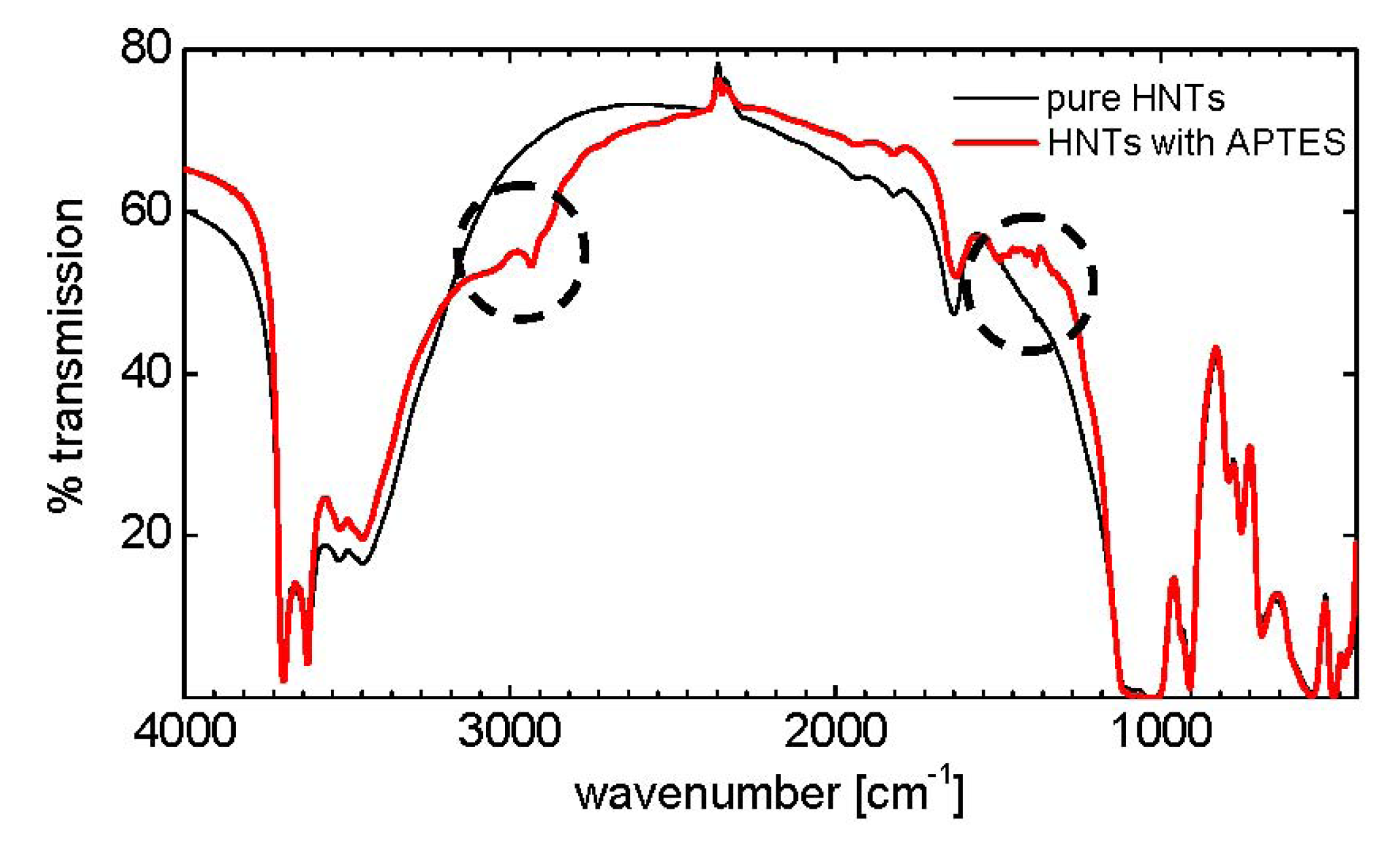
4. Characterization
| Wave number [cm−1] | Mode of vibration |
|---|---|
| 3600–3700 | O–H stretching, inner hydroxyl groups |
| 3400–3500 | O–H stretching, H2O |
| 2900–3000 | C–H stretching, CH2 |
| 1630 | O–H deformation, H2O |
| 1490, 1380 | C–H deformation, CH2 |
| 1020, 1080 | Si–O stretching |
| 900 | O–H deformation, inner hydroxyl groups |
| 790, 750, 700 | Si–O stretching |
| 530 | Al–O–Si deformation |
| 470 | Si–O–Si deformation |
| 430 | Si–O deformation |
5. Results and Discussion
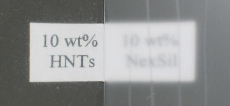
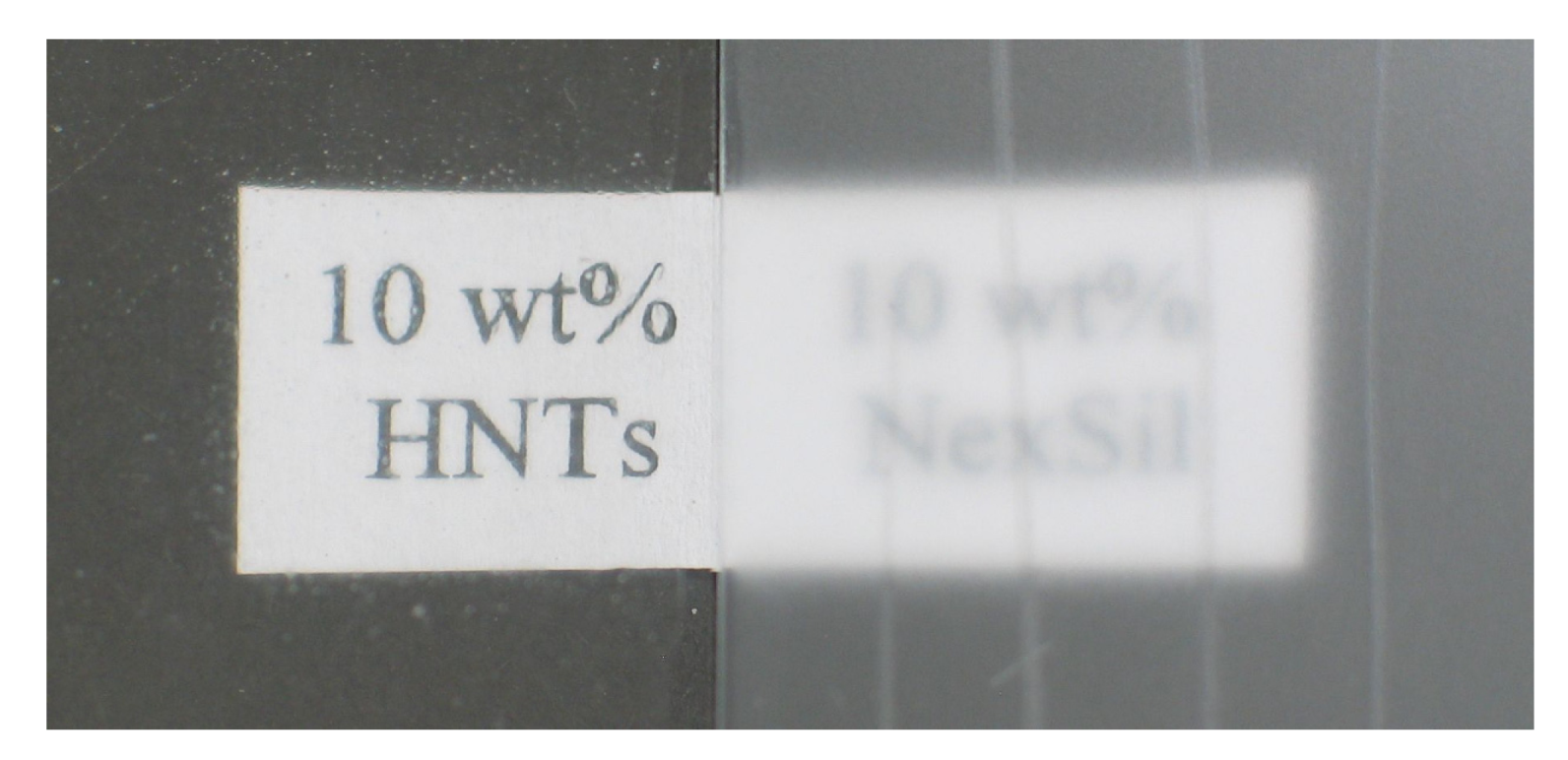
5.1. Optical Appearance
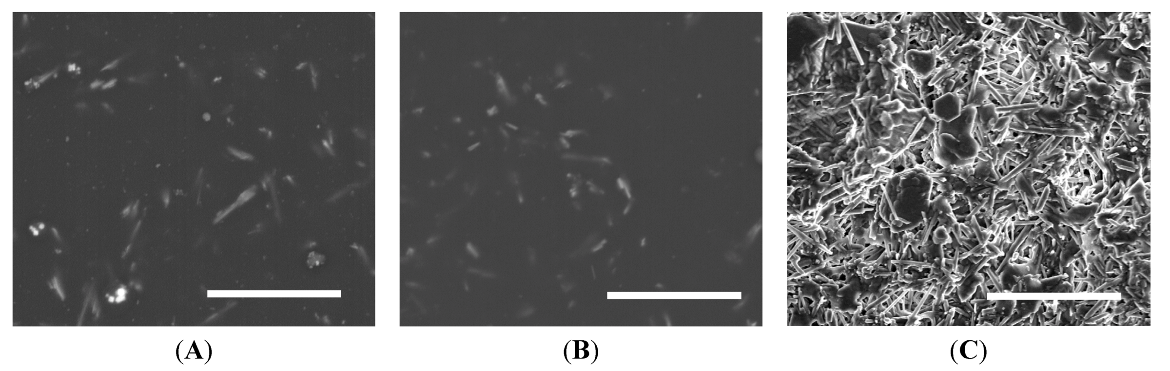
5.2. Scanning Electron Microscopy


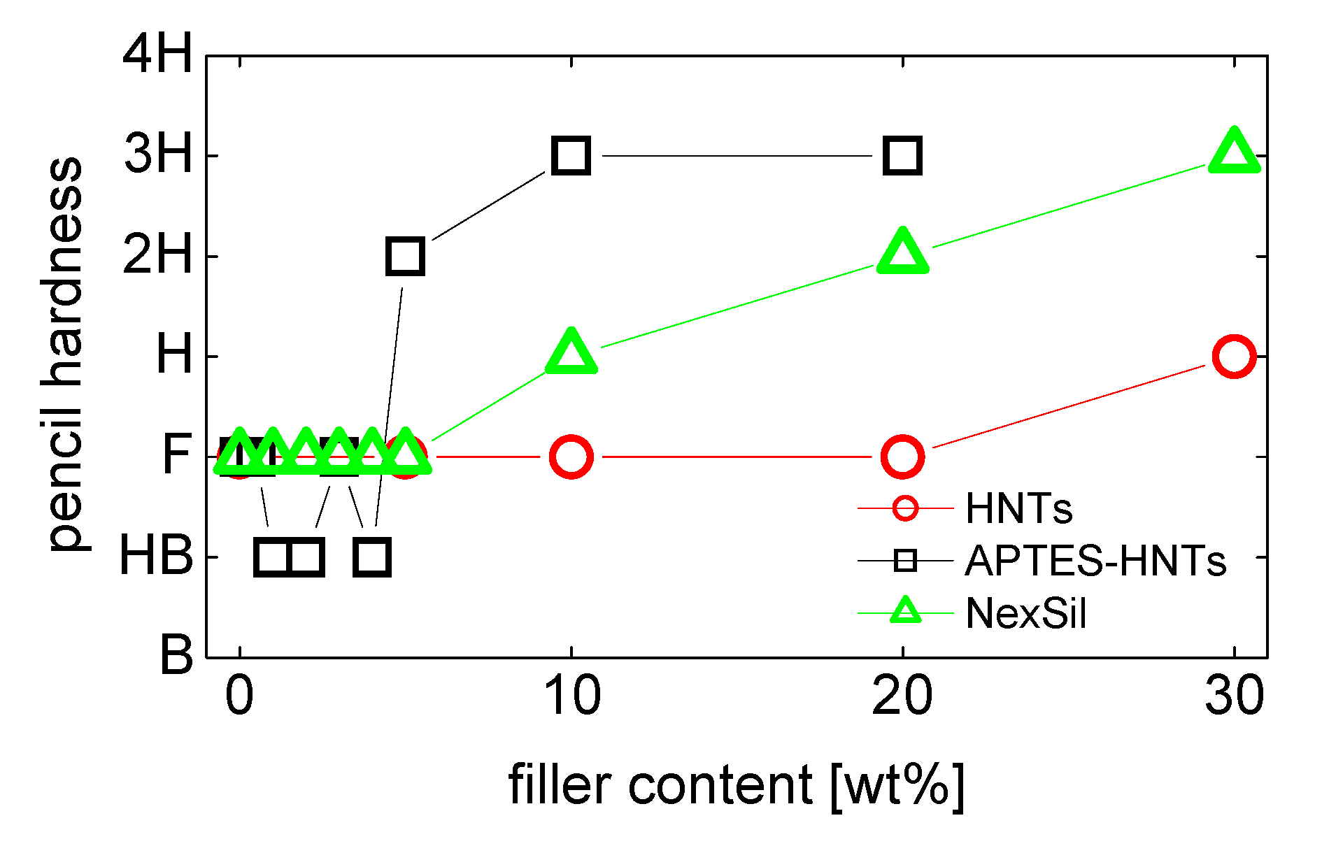
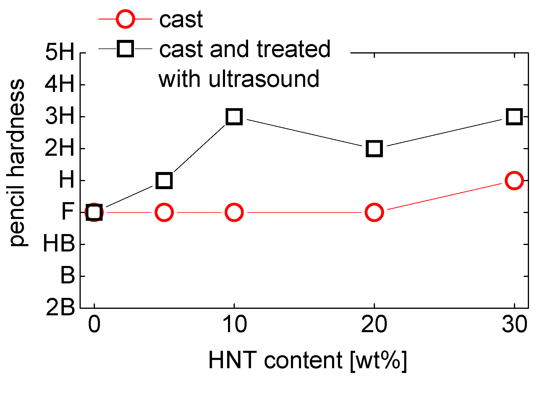
5.3. Pencil Hardness

6. Conclusions
Acknowledgements
References
- Tong, L.; Mouritz, A.P.; Bannister, S.O. 3D Fibre Reinforced Polymer Composites, 1st ed; Elsevier Science & Technology: Amsterdam, The Netherlands, 2002. [Google Scholar]
- Gerhart, H.L. Protective Coatings. Ind. Eng. Chem. 1965, 57, 52–60. [Google Scholar] [CrossRef]
- Seubert, C.; Nietering, K.; Nichols, M.; Wykoff, R.; Bollin, S. An Overview of the Scratch Resistance of Automotive Coatings: Exterior Clearcoats and Polycarbonate Hardcoats. Coatings 2012, 2, 221–234. [Google Scholar] [CrossRef]
- Zhou, S.X.; Wu, L.M.; Sun, J.; Shen, W.D. The change of the properties of acrylic-based polyurethane via addition of nano-silica. Progr. Org. Coating 2002, 45, 33–42. [Google Scholar] [CrossRef]
- Dasari, A.; Yu, Z.Z.; Mai, Y.W. Fundamental aspects and recent progress on wear/scratch damage in polymer nanocomposites. Mater. Sci. Eng. R Rep. 2009, 63, 31–80. [Google Scholar] [CrossRef]
- Friedrich, K.; Zhang, Z.; Schlarb, A.K. Effects of various fillers on the sliding wear of polymer composites. Compos. Sci. Tech. 2005, 65, 2329–2343. [Google Scholar] [CrossRef]
- Mills, D.J.; Jamali, S.S.; Paprocka, K. Investigation into the effect of nano-silica on the protective properties of polyurethane coatings. Surf. Coating Tech. 2012, 209, 137–142. [Google Scholar] [CrossRef]
- Sangermano, M.; Messori, M. Scratch Resistance Enhancement of Polymer Coatings. Macromol. Mater. Eng. 2010, 295, 603–612. [Google Scholar] [CrossRef]
- Howarter, J.A.; Youngblood, J.P. Optimization of silica silanization by 3-aminopropyltriethoxysilane. Langmuir 2006, 22, 11142–11147. [Google Scholar] [CrossRef]
- Mora-Barrantes, I.; Rodriguez, A.; Ibarra, L.; Gonzalez, L.; Valentin, J.L. Overcoming the disadvantages of fumed silica as filler in elastomer composites. J. Mater. Chem. 2011, 21, 7381–7392. [Google Scholar]
- Jordan, J.; Jacob, K.I.; Tannenbaum, R.; Sharaf, M.A.; Jasiuk, I. Experimental trends in polymer nanocomposites—A review. Mater. Sci. Eng. A 2005, 393, 1–11. [Google Scholar] [CrossRef]
- Glasel, H.J.; Bauer, F.; Ernst, H.; Findeisen, M.; Hartmann, E.; Langguth, H.; Mehnert, R.; Schubert, R. Preparation of scratch and abrasion resistant polymeric nanocomposites by monomer grafting onto nanoparticles, 2—Characterization of radiation-cured polymeric nanocomposites. Macromol. Chem. Phys. 2000, 201, 2765–2770. [Google Scholar] [CrossRef]
- Barna, E.; Bommer, B.; Kursteiner, J.; Vital, A.; von Trzebiatowski, O.; Koch, W.; Schmid, B.; Graule, T. Innovative, scratch proof nanocomposites for clear coatings. Compos. Appl. Sci. Manuf. 2005, 36, 473–480. [Google Scholar] [CrossRef]
- Bauer, F.; Ernst, H.; Hirsch, D.; Naumov, S.; Pelzing, M.; Sauerland, V.; Mehnert, R. Preparation of scratch and abrasion resistant polymeric nanocomposites by monomer grafting onto nanoparticles, 5(a)—Application of mass Spectroscopy and atomic force microscopy to the characterization of silane-modified silica surface. Macromol. Chem. Phys. 2004, 205, 1587–1593. [Google Scholar] [CrossRef]
- Amerio, E.; Sangermano, M.; Colucci, G.; Malucelli, G.; Messori, M.; Taurino, R.; Fabbri, P. UV curing of organic-inorganic hybrid coatings containing polyhedral oligomeric silsesquioxane blocks. Macromol. Mater. Eng. 2008, 293, 700–707. [Google Scholar] [CrossRef]
- Jones, R.F. Guide to Short Fiber Reinforced Plastics, 1st ed; Hanser Publishers: Munich, Germany, 1998. [Google Scholar]
- Breuer, O.; Sundararaj, U. Big returns from small fibers: A review of polymer/carbon nanotube composites. Polym. Compos. 2004, 25, 630–645. [Google Scholar] [CrossRef]
- Coleman, J.N.; Khan, U.; Blau, W.J.; Gun’ko, Y.K. Small, but strong: A review of the mechanical properties of carbon nanotube-polymer composites. Carbon 2006, 44, 1624–1652. [Google Scholar] [CrossRef]
- Wang, T.; Lei, C.H.; Liu, D.; Manea, M.; Asua, J.M.; Creton, C.; Dalton, A.B.; Keddie, J.L. A molecular mechanism for toughening and strengthening waterborne nanocomposites. Adv. Mater. 2008, 20, 90–94. [Google Scholar] [CrossRef]
- Wang, T.; Keddie, J.L. Design and fabrication of colloidal polymer nanocomposites. Adv. Colloid Interf. Sci. 2009, 147–148, 319–332. [Google Scholar] [CrossRef] [Green Version]
- Joussein, E.; Petit, S.; Churchman, J.; Theng, B.; Righi, D.; Delvaux, B. Halloysite clay minerals—A review. Clay Minerals 2005, 40, 383–426. [Google Scholar] [CrossRef]
- Lvov, Y.; Price, R. Halloysite Nanotubes in Nanomaterials Research. Available online: http://www.sigmaaldrich.com/materials-science/nanomaterials/nanoclay-building/halloysitenanotubes.html (accessed on 5 July 2011).
- Qiao, J.Q.; Adams, J.; Johannsmann, D. Addition of Halloysite Nanotubes Prevents Cracking in Drying Latex Films. Langmuir 2012, 28, 8674–8680. [Google Scholar] [CrossRef]
- Rawtani, D.; Agrawal, Y.K. Multifarious Applications of Halloysite Nanotubes: A Review. Rev. Adv. Mater. Sci. 2012, 30, 282–295. [Google Scholar]
- Shchukin, D.G.; Lamaka, S.V.; Yasakau, K.A.; Zheludkevich, M.L.; Ferreira, M.G.S.; Mohwald, H. Active anticorrosion coatings with halloysite nanocontainers. J. Phys. Chem. C 2008, 112, 958–964. [Google Scholar]
- Machado, G.S.; Castro, K.; Wypych, F.; Nakagaki, S. Immobilization of metalloporphyrins into nanotubes of natural halloysite toward selective catalysts for oxidation reactions. J. Mol. Catal. A Chem. 2008, 283, 99–107. [Google Scholar] [CrossRef]
- Cho, S.H.; White, S.R.; Braun, P.V. Self-Healing Polymer Coatings. Adv. Mater. 2009, 21, 645–649. [Google Scholar] [CrossRef]
- Levis, S.R.; Deasy, P.B. Characterisation of halloysite for use as a microtubular drug delivery system. Int. J. Pharm. 2002, 243, 125–134. [Google Scholar] [CrossRef]
- Rooj, S.; Das, A.; Heinrich, G. Tube-like natural halloysite/fluoroelastomer nanocomposites with simultaneous enhanced mechanical, dynamic mechanical and thermal properties. Eur. Polym. J. 2011, 47, 1746–1755. [Google Scholar] [CrossRef]
- Barrientos-Ramirez, S.; de Oca-Ramirez, G.M.; Ramos-Fernandez, E.V.; Sepulveda-Escribano, A.; Pastor-Blas, M.M.; Gonzalez-Montiel, A. Surface modification of natural halloysite clay nanotubes with aminosilanes. Application as catalyst supports in the atom transfer radical polymerization of methyl methacrylate. Appl. Catal. A Gen. 2011, 406, 22–33. [Google Scholar] [CrossRef]
- Yuan, P.; Southon, P.D.; Liu, Z.W.; Green, M.E.R.; Hook, J.M.; Antill, S.J.; Kepert, C.J. Functionalization of halloysite clay nanotubes by grafting with gamma-aminopropyltriethoxysilane. J. Phys. Chem. C 2008, 112, 15742–15751. [Google Scholar]
- Datasheet Bayhydrol® A XP 2695. Available online: http://www.bayercoatings.de/BMS/DBRSC/BMS_RSC_CAS.nsf/files/_Industrie/$file/Industrie_Primer_SA_Bayhydrol_A_XP_2695%20d.pdf (accessed on 23 August 2012).
- Desmodur® N 3900. Available online: http://tecci.bayer.de/coatings/emea/de/Desmodur_N_3900_de.pdf?para=bd4ec657b1e201a9dca7a9f0a8bce840 (accessed on 5 September 2012).
- Otts, D.B.; Cueva-Parra, L.A.; Pandey, R.B.; Urban, M.W. Film formation from aqueous polyurethane dispersions of reactive hydrophobic and hydrophilic components; Spectroscopic studies and Monte Carlo simulations. Langmuir 2005, 21, 4034–4042. [Google Scholar] [CrossRef]
- Hesse, M.; Meier, H.; Zeeh, B. Spektroskopische Methoden in der Organischen Chemie, 5 ed; Georg Thieme Verlag: Stuttgart, Germany, 1995. [Google Scholar]
- Foygel, M.; Morris, R.D.; Anez, D.; French, S.; Sobolev, V.L. Theoretical and computational studies of carbon nanotube composites and suspensions: Electrical and thermal conductivity. Phys. Rev. B 2005, 71, 104201. [Google Scholar] [CrossRef]
- Howarter, J.A.; Youngblood, J.P. Self-cleaning and next generation anti-fog surfaces and coatings. Macromol. Rapid Commun. 2008, 29, 455–466. [Google Scholar] [CrossRef]
© 2013 by the authors; licensee MDPI, Basel, Switzerland. This article is an open-access article distributed under the terms and conditions of the Creative Commons Attribution license (http://creativecommons.org/licenses/by/3.0/).
Share and Cite
Li, X.; Nikiforow, I.; Pohl, K.; Adams, J.; Johannsmann, D. Polyurethane Coatings Reinforced by Halloysite Nanotubes. Coatings 2013, 3, 16-25. https://doi.org/10.3390/coatings3010016
Li X, Nikiforow I, Pohl K, Adams J, Johannsmann D. Polyurethane Coatings Reinforced by Halloysite Nanotubes. Coatings. 2013; 3(1):16-25. https://doi.org/10.3390/coatings3010016
Chicago/Turabian StyleLi, Xin, Irina Nikiforow, Katja Pohl, Jörg Adams, and Diethelm Johannsmann. 2013. "Polyurethane Coatings Reinforced by Halloysite Nanotubes" Coatings 3, no. 1: 16-25. https://doi.org/10.3390/coatings3010016